
3RW5217-1AC15 - Uncategorized SIEMENS - Free user manual and instructions
Find the device manual for free 3RW5217-1AC15 SIEMENS in PDF.

| Product Type | Soft Starter |
| Model | 3RW5217-1AC15 |
| Brand | Siemens |
| Rated Operating Voltage | 200-600 V AC |
| Control Supply Voltage | 110-250 V AC, 50/60 Hz |
| Rated Operating Current at 40°C | 38 A |
| Motor Power at 400 V | 18.5 kW |
| Trip Class | CLASS 10A (default) / 10E / 20E |
| Start Ramp Time | 0...20 s |
| Adjustable Current Limit | 130-700% |
| Dimensions (H x W x D) | 275 mm x 170 mm x 152 mm |
| Weight | 2.3 kg |
| Degree of Protection | IP00 |
| Ambient Temperature (Operation) | -25...+60 °C |
| Digital Inputs | 1 |
| Digital Outputs | 3 (2 NO, 1 CO) |
| Analog Output | 4-20 mA (default) / 0-10 V (with HMI) |
| Communication Modules Supported | PROFINET, EtherNet/IP, Modbus RTU, Modbus TCP, PROFIBUS |
| Integrated Bypass Contact | Yes |
| Inside-Delta Circuit Support | Yes |
| Motor Overload Protection | Electronic |
| Certifications | CE, UL, CSA |
| Mounting Type | Screw fixing |
| Main Circuit Connection | Screw terminals |
Frequently Asked Questions - 3RW5217-1AC15 SIEMENS
User questions about 3RW5217-1AC15 SIEMENS
0 question about this device. Answer the ones you know or ask your own.
Ask a new question about this device
Download the instructions for your Uncategorized in PDF format for free! Find your manual 3RW5217-1AC15 - SIEMENS and take your electronic device back in hand. On this page are published all the documents necessary for the use of your device. 3RW5217-1AC15 by SIEMENS.
USER MANUAL 3RW5217-1AC15 SIEMENS
SIRIUS soft starter 200-600 V 38 A, 110-250 V AC Screw terminals Analog output
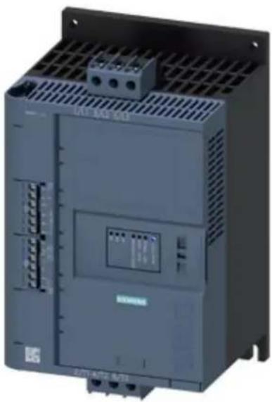
natural_image
Exterior view of a gray industrial control unit (no visible text or symbols)| Product brand name SIRIUS | |
| Product category Hybrid switching devices | |
| Product designation Soft starter | |
| Product type designation 3RW52 | |
| Manufacturer's article number | |
| • of HMI module usable | 3RW5980-0HS00 |
| • of HMI-Modul high-feature usable | 3RW5980-0HF00 |
| • of communication module PROFINET standard usable | 3RW5980-0CS00 |
| • of communication module PROFIBUS usable | 3RW5980-0CP00 |
| • of communication module Modbus TCP usable | 3RW5980-0CT00 |
| • of communication module Modbus RTU usable | 3RW5980-0CR00 |
| • of communication module Ethernet/IP | 3RW5980-0CE00 |
| • of circuit breaker usable at 400 V | 3RV2032-4WA10; Type of coordination 1, lq = 65 kA, CLASS 10 |
| • of circuit breaker usable at 500 V | 3RV2032-4WA10; Type of coordination 1, lq = 10 kA, CLASS 10 |
| • of circuit breaker usable at 400 V at inside-delta circuit | 3RV2032-4RA10; Type of coordination 1, lq = 65 kA, CLASS 10 |
| • of circuit breaker usable at 500 V at inside-delta circuit | 3RV2032-4RA10; Type of coordination 1, lq = 10 kA, CLASS 10 |
• of the gG fuse usable up to 690 V
- of the gG fuse usable at inside-delta circuit up to 500 V
- of full range R fuse link for semiconductor protection usable up to 690 V
- of back-up R fuse link for semiconductor protection usable up to 690 V
3NA3824-6; Type of coordination 1, Iq = 65 kA
3NA3824-6; Type of coordination 1, Iq = 65 kA
3NE1820-0; Type of coordination 2, Iq = 65 kA
3NE8024-1; Type of coordination 2, Iq = 65 kA
| General technical data | |
| Starting voltage [%] 30 ... 100 % | |
| Stopping voltage [%] 50 ... 50 % | |
| Start-up ramp time of soft starter 0 ... 20 s | |
| Current limiting value [%] adjustable 130 ... 700 % | |
| Certificate of suitability | |
| • CE marking | Yes |
| • UL approval | Yes |
| • CSA-approval | Yes |
| Product component | |
| • is supported HMI-Standard | Yes |
| • is supported HMI-High Feature | Yes |
| Product feature integrated bypass contact system Yes | |
| Number of controlled phases 3 | |
| Trip class CLASS 10A (default) / 10E / 20E; acc. to IEC | 60947-4-2 |
| Insulation voltage | |
| • rated value | 600 V |
| Degree of pollution 3, acc. to IEC 60947-4-2 | |
| Impulse voltage rated value 6 kV | |
| Blocking voltage of the thyristor maximum 1 600 V | |
| Service factor 1 | |
| Surge voltage resistance rated value 6 kV | |
| maximum permissible voltage for safe isolation | |
| • between main and auxiliary circuit | 600 V |
| Protection class IP IP00 | |
| Usage category acc. to IEC 60947-4-2 AC 53a | |
| Shock resistance 15 g / 11 ms, from 12 g / 11 ms with potential contact lifting | |
| Vibration resistance 15 mm to 6 Hz; 2g to 500 Hz | |
| Reference code acc. to DIN EN 81346-2 | Q |
| Product function | |
| • ramp-up (soft starting) | Yes |
| • ramp-down (soft stop) | Yes |
| • Soft Torque | Yes |
| • Adjustable current limitation | Yes |
| • pump ramp down | Yes |
| Intrinsic device protection | Yes |
| motor overload protection | Yes; Electronic motor overload protection |
| Evaluation of thermistor motor protection | No |
| Inside-delta circuit | Yes |
| Auto-reset | Yes |
| Manual RESET | Yes |
| remote reset | Yes; By turning off the control supply voltage |
| communication function | Yes |
| Operating measured value display | Yes |
| error logbook | Yes |
| via software parameterizable | No |
| via software configurable | Yes |
| PROFlenergy | Yes; in connection with the PROFINET Standard communication module |
| firmware update | Yes |
| removable terminal for control circuit | Yes |
| torque control | No |
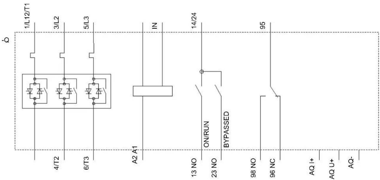
| analog output | Yes; 4 ... 20 mA (default) / 0 ... 10 V (parameterizable with High Feature HMI) |
Power Electronics
| Operating current | |
| • at 40 °C rated value | 38 A |
| • at 50 °C rated value | 33.5 A |
| • at 60 °C rated value | 30.5 A |
| Operating current at inside-delta circuit | |
| • at 40 °C rated value | 65.8 A |
| • at 50 °C rated value | 58 A |
| • at 60 °C rated value | 52.8 A |
| Operating voltage | |
| • rated value | 200 ... 600 V |
| • at inside-delta circuit rated value | 200 ... 600 V |
| Relative negative tolerance of the operating voltage -15 % | |
| Relative positive tolerance of the operating voltage 10 % | |
| Relative negative tolerance of the operating voltage at inside-delta circuit | -15 % |
| Relative positive tolerance of the operating voltage at inside-delta circuit | 10 % |
| Operating power for three-phase motors | |
| • at 230 V at 40 °C rated value | 11 kW |
| • at 230 V at inside-delta circuit at 40 °C rated value | 18.5 kW |
| • at 400 V at 40 °C rated value | 18.5 kW |
| at 400 V at inside-delta circuit at 40 °C rated value | 30 kW |
| at 500 V at 40 °C rated value | 22 kW |
| at 500 V at inside-delta circuit at 40 °C rated value | 37 kW |
| Operating frequency 1 rated value 50 Hz | |
| Operating frequency 2 rated value 60 Hz | |
| Relative negative tolerance of the operating frequency | -10 % |
| Relative positive tolerance of the operating frequency 10 % | |
| Adjustable motor current | |
| at rotary encoding switch on switch position 1 | 15.5 A |
| at rotary encoding switch on switch position 3 | 18.5 A |
| at rotary encoding switch on switch position 4 | 20 A |
| at rotary encoding switch on switch position 5 | 21.5 A |
| at rotary encoding switch on switch position 6 | 23 A |
| at rotary encoding switch on switch position 7 | 24.5 A |
| at rotary encoding switch on switch position 8 | 26 A |
| at rotary encoding switch on switch position 9 | 27.5 A |
| at rotary encoding switch on switch position 10 | 29 A |
| at rotary encoding switch on switch position 11 | 30.5 A |
| at rotary encoding switch on switch position 12 | 32 A |
| at rotary encoding switch on switch position 13 | 33.5 A |
| at rotary encoding switch on switch position 14 | 35 A |
| at rotary encoding switch on switch position 15 | 36.5 A |
| at rotary encoding switch on switch position 16 | 38 A |
| minimum | 15.5 A |
| at inside-delta circuit minimum | 26.8 A |
| Adjustable motor current for inside-delta circuit | |
| at rotary encoding switch on switch position 1 | 26.8 A |
| at rotary encoding switch on switch position 2 | 29.4 A |
| at rotary encoding switch on switch position 3 | 32 A |
| at rotary encoding switch on switch position 4 | 34.6 A |
| at rotary encoding switch on switch position 5 | 37.2 A |
| at rotary encoding switch on switch position 6 | 39.8 A |
| at rotary encoding switch on switch position 7 | 42.4 A |
| at rotary encoding switch on switch position 8 | 45 A |
| at rotary encoding switch on switch position 9 | 47.6 A |
| at rotary encoding switch on switch position 10 | 50.2 A |
| at rotary encoding switch on switch position 11 | 52.8 A |
| at rotary encoding switch on switch position 12 | 55.4 A |
| at rotary encoding switch on switch position 13 | 58 A |
| • at rotary encoding switch on switch position 14 | 60.6 A |
| • at rotary encoding switch on switch position 15 | 63.2 A |
| • at rotary encoding switch on switch position 16 | 65.8 A |
| Minimum load [%] 15 %; Relative to smallest settable le | |
| Power loss [W] for rated value of the current at AC | |
| • at 40 °C to power-up | 23 W |
| • at 50 °C to power-up | 22 W |
| • at 60 °C to power-up | 21 W |
| Power loss [W] at AC at AC | |
| • at 60 °C during startup | 464 W |
| • at 50 °C during startup | 526 W |
Control circuit/ Control
| Type of voltage of the control supply voltage AC | |
| Control supply voltage at AC | |
| • at 50 Hz | 110 ... 250 V |
| • at 60 Hz | 110 ... 250 V |
| Relative negative tolerance of the control supply voltage at AC at 50 Hz | -15 % |
| Relative positive tolerance of the control supply voltage at AC at 50 Hz | 10 % |
| Relative negative tolerance of the control supply voltage at AC at 60 Hz | -15 % |
| Relative positive tolerance of the control supply voltage at AC at 60 Hz | 10 % |
| Control supply voltage frequency 50 ... 60 Hz | |
| Relative negative tolerance of the control supply voltage frequency | -10 % |
| Relative positive tolerance of the control supply voltage frequency | 10 % |
| Control supply current in standby mode rated value 30 mA | |
| Holding current in the by-pass mode operating rated value | 75 mA |
| Starting current at close of by-pass contact maximum 0.17 A | |
| Inrush current peak at connect of control supply voltage maximum | 12.2 A |
| Duration of inrush current peak at connect of control supply voltage | 2.2 ms |
| Design of the overvoltage protection Varistor | |
| Design of short-circuit protection for control circuit | 4 A gG fuse (Icu=1 kA), 6 A quick-acting fuse (Icu=1 kA), C1 miniature circuit breaker (Icu= 600 A), C6 miniature circuit breaker (Icu= 300 A); Is not part of scope of supply |
Inputs/ Outputs
| Number of digital inputs 1 | |
| Number of inputs for thermistor connection 0 | |
| Number of digital outputs 3 | |
| • not parameterizable | 2 |
| Digital output version 2 normally-open contacts (NO) / 1 | changeover contact (CO) |
| Number of analog outputs 1 | |
| Switching capacity current of the relay outputs | |
| • at AC-15 at 250 V rated value | 3 A |
| • at DC-13 at 24 V rated value | 1 A |
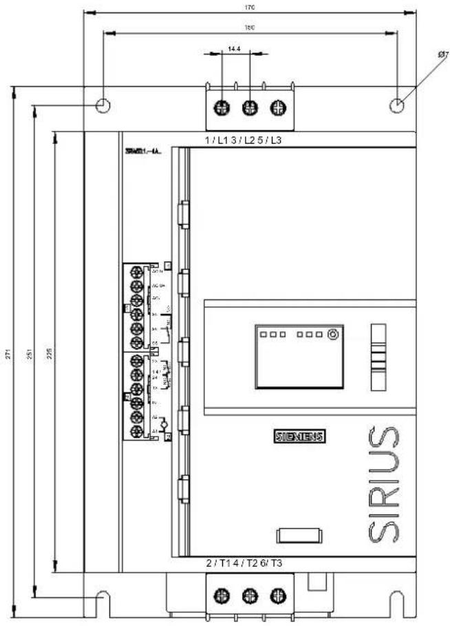
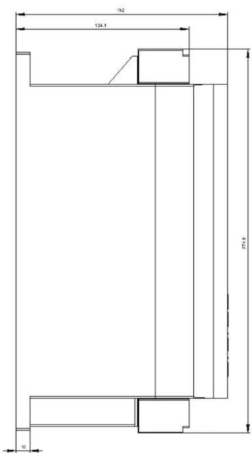
| Installation/ mounting/ dimensions | |
| Mounting position with vertical mounting surface +/-90° rotatable, with vertical mounting surface +/- 22.5° tiltable to the front and back | |
| Mounting type screw fixing | |
| Height 275 mm | |
| Width 170 mm | |
| Depth 152 mm | |
| Required spacing with side-by-side mounting | |
| • forwards | 10 mm |
| • Backwards | 0 mm |
| • upwards | 100 mm |
| • downwards | 75 mm |
| • at the side | 5 mm |
| Installation altitude at height above sea level maximum | 5 000 m; Derating as of 1000 m, see catalog |
| Weight without packaging 2.3 kg | |
| Connections/ Terminals | |
| Type of electrical connection | |
| • for main current circuit | screw-type terminals |
| • for control circuit | screw-type terminals |
| Type of connectable conductor cross-sections | |
| • for main contacts | |
| — solid | 2x (1.0 ... 2.5 mm ^2 ), 2x (2.5 ... 10 mm ^2 ) |
| — finely stranded with core end processing | 2x (1.0 ... 2.5 mm ^2 ), 2x (2.5 ... 6.0 mm ^2 ) |
| • at AWG conductors for main current circuit solid | 2x (16 ... 12), 2x (14 ... 8) |
| Type of connectable conductor cross-sections | |
| • for control circuit solid | 1x (0.5 ... 4.0 mm ^2 ), 2x (0.5 ... 2.5 mm ^2 ) |
| • for control circuit finely stranded with core end processing | 1x (0.5 ... 2.5 mm ^2 ), 2x (0.5 ... 1.5 mm ^2 ) |
| • at AWG conductors for control circuit solid | 1x (20 ... 12), 2x (20 ... 14) |
| Wire length | |
| • between soft starter and motor maximum | 800 m |
| • at the digital inputs at AC maximum | 100 m |
Ambient conditions
| Ambient temperature | |
| • during operation | -25 ... +60 °C; Please observe derating at temperatures of 40 °C or above |
| • during storage and transport | -40 ... +80 °C |
| Environmental category | |
| • during operation acc. to IEC 60721 | 3K6 (no ice formation, only occasional condensation), 3C3 (no salt mist), 3S2 (sand must not get into the devices), 3M6 |
| • during storage acc. to IEC 60721 | 1K6 (only occasional condensation), 1C2 (no salt mist), 1S2 (sand must not get inside the devices), 1M4 |
| • during transport acc. to IEC 60721 | 2K2, 2C1, 2S1, 2M2 (max. fall height 0.3 m) |
EMC emitted interference acc. to IEC 60947-4-2: Class A
Communication/ Protocol
| Communication module is supported | |
| • PROFINET standard | Yes |
| • EtherNet/IP | Yes |
| • Modbus RTU | Yes |
| • Modbus TCP | Yes |
| • PROFIBUS | Yes |
UL/CSA ratings
| Manufacturer's article number | |
| • of circuit breaker | |
| — usable for Standard Faults at 460/480 V according to UL | Iq = 5 kA |
| — usable for High Faults at 460/480 V according to UL | Iq max = 65 kA |
| — usable for Standard Faults at 460/480 V at inside-delta circuit according to UL | Iq = 5 kA |
| — usable for High Faults at 460/480 V at inside-delta circuit according to UL | Iq max = 65 kA |
| — usable for Standard Faults at 575/600 V according to UL | Iq = 5 kA |
| — usable for Standard Faults at 575/600 V at inside-delta circuit according to UL | Iq = 5 kA |
| • of the fuse | |
| — usable for Standard Faults up to 575/600 V according to UL | Type: Class RK5 / K5, max. 150 A; Iq = 5 kA |
| — usable for High Faults up to 575/600 V according to UL | Type: Class J / L, max. 150 A; Iq = 100 kA |
| — usable for Standard Faults at inside-delta circuit up to 575/600 V according to UL | Type: Class RK5 / K5, max. 150 A; Iq = 5 kA |
| — usable for High Faults at inside-delta circuit up to 575/600 V according to UL | Type: Class J / L, max. 150 A; Iq = 100 kA |
| Operating power [hp] for three-phase motors | |
| • at 200/208 V at 50 °C rated value | 10 hp |
| • at 220/230 V at 50 °C rated value | 10 hp |
| • at 460/480 V at 50 °C rated value | 20 hp |
| • at 575/600 V at 50 °C rated value | 30 hp |
| • at 200/208 V at inside-delta circuit at 50 °C rated value | 15 hp |
| • at 220/230 V at inside-delta circuit at 50 °C rated value | 20 hp |
| • at 460/480 V at inside-delta circuit at 50 °C rated value | 40 hp |
| • at 575/600 V at inside-delta circuit at 50 °C rated value | 50 hp |
Contact rating of auxiliary contacts according to UL R300-B300
Electromagnetic compatibility in accordance with IEC 60947-4-2
Certificates/ approvals
| General Product Approval EMC Declaration of | Conformity | ||||
 |  |  |  |  |  |
| CCC | CSA | UL | RCM | EG-Konf. | |
| Declaration of Conformity | Test Certificates | Marine / Shipping other | |||
| Miscellaneous Type Test Certificates/Test Report | ABS | Lloyd's Register | PRS | Confirmation | |
Further information
Information- and Downloadcenter (Catalogs, Brochures,...)
www.siemens.com/sirius/catalogs
Industry Mall (Online ordering system)
https://mall.industry.siemens.com/mall/en/en/Catalog/product?mlfb=3RW5217-1AC15
Cax online generator
http://support.automation.siemens.com/WW/CAXorder/default.aspx?lang=en&mlfb=3RW5217-1AC15
Service&Support (Manuals, Certificates, Characteristics, FAQs,...)
https://support.industry.siemens.com/cs/ww/en/ps/3RW5217-1AC15
Image database (product images, 2D dimension drawings, 3D models, device circuit diagrams, EPLAN macros, ...)
http://www.automation.siemens.com/bilddb/cax_de.aspx?mlfb=3RW5217-1AC15&lang=en
Characteristic: Tripping characteristics, I²t, Let-through current
https://support.industry.siemens.com/cs/ww/en/ps/3RW5217-1AC15/char
Characteristic: Installation altitude
http://www.automation.siemens.com/bilddb/index.aspx?view=Search&mlfb=3RW5217-1AC15&objecttype=14&gridview=view1
last modified:
09/18/2019

Brand : SIEMENS
Model : 3RW5217-1AC15
Category : Uncategorized