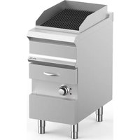
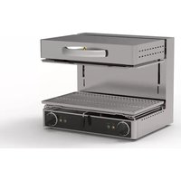
WGE74 - Grill plate MBM - Free user manual and instructions
Find the device manual for free WGE74 MBM in PDF.


| Product type | Professional grill plate |
| Brand | MBM |
| Model | WGE74 |
| Usage | Cooking food (grill) in commercial catering |
| Power supply | Single-phase or three-phase depending on configuration (see rating plate) |
| Water capacity of containers | 5.5 liters per container (model WGE7...) |
| Main material | Stainless steel |
| Temperature adjustment | Rotary thermostat with green (on) and yellow (heating) indicator lights |
| Safety | Automatic shutdown in case of anomaly (safety component) |
| Noise level | ≤ 70 dB(A) |
| Max ambient humidity | 80 % RH |
| Min ambient temperature | +10 °C |
| Cleaning | Manual, with non-abrasive sponge and detergent with pH>12 without chlorides |
| Periodic maintenance | Annual inspection by a certified technician |
| Spare parts | Exclusively MBM original parts |
| Warranty | 12 months from invoice date (parts) |
| Environmental compliance | WEEE directive - separate collection at end of life |
Frequently Asked Questions - WGE74 MBM
User questions about WGE74 MBM
0 question about this device. Answer the ones you know or ask your own.
Ask a new question about this device
Download the instructions for your Grill plate in PDF format for free! Find your manual WGE74 - MBM and take your electronic device back in hand. On this page are published all the documents necessary for the use of your device. WGE74 by MBM.
USER MANUAL WGE74 MBM
INSTALLATIONS AND USE INSTRUCTIONS
GRILL À EAU
MANUEL D'INSTALLATION ET D'UTILISATION
PARRILLA DE AGUA
RISCHIO RESIDUO DI USTIONE PER FUORIU- SCITA MATERIALE /
Danger indications. Immediate hazardous situation which could result in serious injury or death. Possibly dangerous situation that could cause serious injury or death.

High voltage! Caution! Danger of death! Non-observance can cause se-injury or death

Pericolo Risk of high temperatures, non-compliance may result in serious injury ath.

Danger of leakage of high-temperature materials, non-observance can cause serious injury or death.

Danger of crushing of limbs during handling and / or positioning, non-compliance may result in serious injury or death.

Prohibition indications.
Unauthorised persons (including children, disabled individuals and people with limited physical, sensory and men-
tal abilities) are prohibited from performing any procedures. Children being supervised not to play with the appliance. Cleaning and user maintenance shall not be made by children without supervision. Prohibition for the heterogeneous operator to perform any type of operation (maintenance and/or other) that should instead be carried out by a qualified and authorised technician. Prohibition for the homogeneous operator to perform any type of operation (maintenance and/or other) without having first read the entire documentation specifics.

Obligation indications.
Obligation to read the instructions before carrying my work.

Obligation to exclude the power supply upstream of the appliance whenever it is necessary to operate safely.

Obligation to use safety goggles.

Obligation to use protective gloves.

Obligation to use a pro- tective helmet.

Obligation to use safety shoes.

Other indications. Indications to implement the correct procedure, non-comance may cause a dangerous

Advice and suggestions to ensure the correct usage cedure.

"Homogeneous" Operator (Qualified Technician). Expert operator authorised andling, transporting, instal-
ling, servicing, repairing and scrapping the appliance.

"Heterogeneous" Operator (Operator with limited skills and tasks). Person comprised and employed to operate the appliance with guards, capable of performing the tasks.

Earthing symbol

Symbol for attachment to the Equipotential system


Obligation to respect the regulations for waste disposal.

GENERAL AND SAFETY INFORMATION
1.
FOREWORD / This document has been drawn up in the mother language of the manufacturer (Italian).
The information it contains is for the sole use of the operator authorised to use the appliance in question.
Operators must be trained concerning all aspects regarding functioning and safety. Special safety prescriptions (Obligations-Prohibitions-Dangers) are carried in a specific chapter concerning these issues. This document cannot be handed over to third parties to take vision of it without written consent by the manufacturer. The text cannot be used in other publications without the written consent of the manufacturer.
The use of: Figures/Images/Drawings/Layouts inside the document, is purely indicative and can undergo variations. The manufacturer reserves the right to modify it, without being obliged to communicate his acts.
PURPOSE OF THE DOCUMENT /
Every type of interaction between the operator and the appliance during its entire life cycle has been carefully assessed both during designing and while drawing up this document. We therefore hope that this documentation can help to maintain the characteristic efficiency of the appliance.
By strictly keeping to the indications it contains, the risk of injuries while working and/or of economical damage is limited to a minimum.
HOW TO READ THE DOCUMENT / The document is divided into chapters which gather by topics all the information required to use the appliance in a risk-free way. Each chapter is divided into paragraphs; each paragraph can have titled clarifications with subtitles and descriptions.
KEEPING THE DOCUMENT / This document and the rest of the contents of the envelope, are an integral part of
the initial supply. It must therefore be kept and used appropriately during the entire operational life of the appliance.
ADDRESSEES / This document is drawn up as follows:
- Homogeneous operator / Expert operator authorised for handling, transporting, installing, servicing, repairing and scrapping the equipment.
- Generic operator / Person authorised and employed to operate the appliance with guards active, capable of performing routine tasks.
OPERATOR TRAINING
PROGRAM / By specific request, it is possible to carry out a training course for users, installers and technicians, following the procedures indicated in the order confirmation.
PRE-ARRANGEMENTS DEPENDING ON CUSTOMER /
Unless different contractual agreements were made, the following normally depend on the customer:
- setting up the rooms (including masonry work, foundations or channelling that could be requested);
- smooth, slip-proof floor;
- pre-arrangement of installation place and installation of equipment respecting the dimensions indicated in the layout (foundation plan);
- pre-arrangement of auxiliary services adequate for requirements of the system (electrical mains, waterworks, gas network, drainage system);
- pre-arrangement of electrical system in compliance with regulatory provisions in force in the place of installation;
- sufficient lighting, in compliance with standards in force in the place of installation;
- safety devices upstream and downstream the energy supply line (residual current devices, equipotential earthing systems, safety valves, etc.) foreseen by legislation in force in the country of
installation;
- earthing system in compliance with standards in force;
- pre-arrangement of a water softening system, if needed (see technical details).
CONTENTS OF THE SUPPLY /
The supply vary depending on the order. • Appliance • Lid/s • Metallic rack/s
- Rack support grid • Pipes and/or wires for connections to energy sources (only when indicated in work order).
INTENDED USE / This device is intended for professional use. The use of the appliance treated in this document must be considered “Proper Use” if used for cooking or regeneration of goods intended for alimentary use; any other use is to be considered “Improper use” and therefore dangerous.
These appliances are intended for commercial activities (e.g. restaurant kitchens, canteens etc) and in commercial companies (e.g. bakeries etc.) but not for the continuous food production.
The appliance must be used according to the foreseen conditions stated in the contract within the prescribed capacity limits carried in the respective paragraphs.
Only use original accessories and spare parts supplied by the manufacturer to maintain regulatory compliance.
ALLOWED OPERATING
CONDITIONS / The appliance has been designed to operate only inside of rooms within the prescribed technical and capacity limits. The following indications must be observed in order to attain ideal operation and safe work conditions.
The appliance must be installed in a suitable place, namely, one which allows normal running, routine and extraordinary maintenance operations. The operating area for maintenance must be set
up in such a way that the safety of the operator is not endangered. The room must also be provided with the features required for installation, such as:
• maximum relative humidity: 80%;
- minimum cooling water temperature > + 10 °C ;
- the floor must be anti-slip, and devices positioned perfectly level;
- the room must be equipped with a ventilation system and lighting as prescribed by standards in force in the country of the user;
- the room must be set up for draining greywater, and must have switches and gate valves which cut all types of supply upstream the appliance when needed;
- The walls/surfaces immediately close/contact to the appliance must be fireproof and/or isolated from possible source of heat
TEST INSPECTION AND WARRANTY / Testing: the equipment has been tested by the manufacturer during the assembly stages at the site of the production plant. All certificates related to the testing performed will be delivered to the customer upon request. Guarantee: the warranty is 12 months from the date of invoicing of the equipment, this period cannot be extended. It covers the faulty parts only. Carriage and installation charges are for the buyer's account. Electric components, accessories as well as other removable parts are not covered by the guarantee. Labor costs relating to the intervention of authorized by the manufacturer at the customer's premises, for removal of defects under warranty are charged to the dealer. Excluded are all tools and supplies, possibly supplied by the manufacturer together with the machines. Damage occurred in transit or due to incorrect installation or maintenance can't be considered. Guarantee is not transferable and replacement of parts and appliance is at the final discre-
tion of our company. The Manufacturer is responsible for the equipment in its original configuration and only for original spare parts replacement. The manufacturer declines all responsibility for improper use, for damages caused as a result of operations not covered in this manual or not authorized in advance by the manufacturer.consideration in this manual or without prior authorisation of the manufacturer himself.
THE WARRANTY TERMINATES IN CASE OF / • Damage caused by transport “ex works” (EXW) and / or by handling, should this event occur, the customer must inform the retailer and the carrier (eg. via e-mail and / or website) and write down on the copies of the transport documents what It’s happened. The technician authorized to install the appliance will evaluate the damage and decide if the installation can be carried out.
The warranty also terminates in the presence of: • Damage caused by incorrect installation. / • Damage caused by parts worn due to improper use. / • Damage caused by use of non-original spare parts. / • Damage caused by incorrect maintenance and/or lack of maintenance. / • Damage caused by failure to comply with the procedures described in this document.
AUTHORISATION / Authorisation refers to the permission to operate an activity intrinsic to the appliance. Authorisation is given to anyone who is responsible for the appliance (manufacturer, purchaser, signer, dealer and/or location owner).
TECHNICAL DATA and IMAGES / The section is at the ending of this manual.

Every technical change has an effect on the operation or of the appliance and must
therefore be performed by technical personnel of the manufacturer or by technicians who are formally authorised by the same. Failure to do so exempts the manufacturer from any liability for for any possible resulting modifications or damage.
Upon arrival, check the integrity of the appliance and its components (e.g. power cord), prior to use. In the presence of faults do not start the appliance and contact the nearest service centre.
Read the instructions before acting.
Wear protective equipment suitable for the operations to be performed. As far as personal protective equipment is concerned, the European Community has issued Directives which the operators must comply with. Noise ≤70 dB.
It is forbidden the installation of stand alone equipment WITHOUT anti-tip kit (ACCESSORY). TOP versions excluded.
Before making the connections check the technical data shown on the rating plate of the appliance and the technical data in this manual. It is strictly forbidden to tamper with or remove the plates and pictograms applied to the equipment.
Disconnect all supplies (water - gas - electrical) upstream the appliance whenever you need to work in safe conditions.
Connect the appliance in the sequence of the water, then to the gas network. Ensure there are no leaks then proceed with the connections to the mains.
The appliance is not designed to work in an explosive atmosphere and as such its installation and use is categorically prohibited in such environments.
Position the entire structure, respecting the installation dimensions and characteristics indicated in the specific chapters of this manual.
The appliance is not intended for recessed installation. / The appliance must be used in a well ventilated area. / The appliance must have free drainage (not hindered or impeded by foreign bodies).
The gas equipment must be installed beneath an extraction hood whose system must have specifications in compliance with the current regulations in the country of use.
Once the appliance is connected to the power and drain sources, it must remain static (fixed) in the place of use and maintenance. Incorrect connection may cause danger.
Use where appropriate flexible cable for connection to the mains electricity supply with characteristics not inferior to the type with insulation model H07RN-F. The supply voltage supported by the cable with the appliance working must not differ from the nominal voltage value ± 15% shown at the bottom of the technical data table.
The appliance must be included in an "Equipotential" ground discharge system.
Drainage of the appliance must
be conveyed into the grey water discharge network in an open “glass” unsiphoned formation.
The appliance must only be used for the purposes indicated. Any other use must be considered "IMPROPER" and therefore the manufacturer declines all liability for any consequent damage to persons or property.
Particular safety prescriptions (obligation - prohibitions - danger) are detailed in the specific chapter concerning these issues.
Do not obstruct the heat extraction and/or dissipation openings.
Do not leave flammable objects or material near the appliance.
Disconnect all supplies (water - gas - electrical) upstream the appliance whenever you need to work in safe conditions.
Whenever it is necessary to operate inside the appliance (connections, commissioning, checking operations, etc.) prepare for the necessary operations (removal of panels, elimination of electric-gas-power supply) in compliance with the safety conditions.
DUTIES AND QUALIFICATIONS REQUIRED OF OPERATORS
Prohibition for the homogeneous operator to perform any type of operation (maintenance and/or other) without having first read the entire documentation.
The information contained in this document is for the use of the qualified technical operator who is authorised for: handling, installation and maintenance of the appliance in question.
The operating instructions have been drawn up for the “Generic” operator (Operator with limited responsibilities and tasks). Person authorised and employed to operate the appliance with guards active and capable of performing routine maintenance (cleaning the appliance).
The operators who use the appliance must be trained in all aspects concerning its functioning and safety features. They must therefore interact using appropriate methods and instruments, complying with required safety standards.
The "Generic" operator must operate on the appliance after the technician has completed installation (transportation, fixing electrical, water, gas and drain connections).
WORK AREAS AND HAZARDOUS ZONES /
To better define the scope of intervention and the relevant work zones, the following classification is provided:
- Dangerous zone: any zone within and/or in proximity to a machine in which the presence of an exposed person constitutes a risk in terms of the health and safety of such a person;
- Exposed person: any person that is found wholly or partly in a dangerous zone.
Maintain a minimum distance from the appliance when operating in such a way as to avoid endangering the safety of the operator in case of unexpected circumstances.
The following are also danger zones /
- All the work areas within the appliance
- All the areas protected by appropriate safety and protection systems such as safety photocell photoelectric curtains, protective panels, interlocked doors, protective casing.
- All the zones within the control units, electrical cabinets and junction boxes.
- All the zones around the appliance in operation when the minimum safety distances are not being respected.
EQUIPMENT REQUIRED FOR INSTALLATION /
The authorised technical operator, in order to perform the installation operations correctly, must respect the following requirements: - 3 and 8 mm screwdriver
- Adjustable pipe wrench
- Gas use tools (hoses, gaskets etc.)
- Electrician's scissors
- Water use tools (hoses etc.)
- 8 mm hex socket wrench
- Gas leak detector
- Tools for electric use (cables, terminal blocks, industrial sockets etc.)
- 8 mm nut driver
- Complete installation set (ele etc.)
In addition to the tools listed, an equipment lifting device is required. This equipment must comply with all the regulations relating to lifting equipment.
INDICATION ON RESIDUAL
RISK / Even though the rules for "good manufacturing practice" and the provisions of law which regulate manufacturing and marketing of the product have been implemented, "residual risks" still remain which, due to the very nature of the appliance, it has not been possible to eliminate. These risks include:

RESIDUAL RISK OF ELECTROCUTION/
This risks remains when intervening on live electrical and/or electronic devices.

RESIDUAL RISK OF BUR- NING / This risks remains
when unintentionally coming into contact with materials at high temperatures.

RESIDUAL RISK OF BURNS DUE TO LEAKING OF MATERIAL / This risks remains
when unintentionally coming into contact with materials at high temperatures. Containers that are too full of liquids or solids that during warming change morphology (changing from a solid to a liquid), can, if used incorrectly, cause burns. During operations, the containers used must be placed on easily visible levels.

RESIDUAL RISK OF CRU- SHING LIMBS / This risk exi- sts where there is accidental
contact between the parts during positioning, transportation, storage and assembly.

RESIDUAL RISK OF EXPLOSIONS /
This risk remains when:
• there is smell of gas in the room;
- appliance used in an atmosphere containing substances which risk exploding;
• using food in closed containers (such as jars and cans), if they are not suitable for the purpose.

RESIDUAL RISK OF FIRE /
This risk exists by flammable liquids / material flammable.

Before proceeding with the ope-
rations, see "General safety information".
OBLIGATIONS - PROHIBITIONS - ADVICE
Upon receipt, open the machine packaging and ensure that the machine and accessories have not been damaged during transportation. Where this is found to be the case, notify the carrier immediately and do not proceed with installation but contact the qualified and authorised personnel. The manufacturer is not liable for damage caused during transportation.
HANDLING SAFETY /

Failure to follow the instructions reported below could result in exposure to the risk of serious injury.
The operator authorised for the handling and installation operations of the appliance must prepare, if necessary, a “safety plan” in order to ensure the safety of the persons involved in the operations. In addition, they must follow and strictly and scrupulously implement the laws and regulations relating to mobile sites.

Ensure that the lifting means adopted have capacity that is adequate for the loads to be lifted in a good state of maintenance.

Perform the handling operations using lifting means with a capacity appropriate to the weight of pliance increased by 20%.

Follow the directions on the packaging and/or on the same appliance before handling.

Check the centre of gravity of the load before lifting the appliance.

Lift the appliance to a minimum height from the ground in order to ensure its handling. Do not stand or pass under the ap-
pliance during lifting and handling.
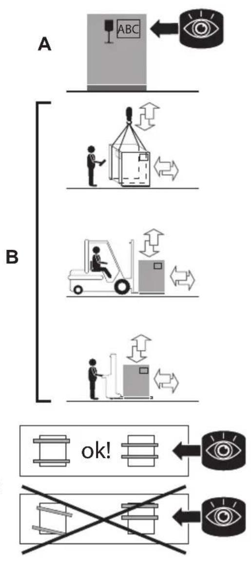
HANDLING - TRANSPORTATION / - see SECT. IMAGES - REF. a).
The orientation of the packed appliance must be maintained according to the instructions given by the pictograms and lettering on the outer packaging (detail A).
- Position the lifting means paying attention to the centre of gravity of the load to be lifted (detail B-C).
- Lift the appliance enough to move it.
- Place the appliance on the site chosen for final positioning.
STORAGE / The storage methods of the materials must include pallets, containers, conveyors, vehicles, tools and lifting devices that are suitable to prevent damage due to vibration, impact, abrasion, corrosion, temperature or other conditions that might arise. The parts stored should be periodically checked to detect possible deterioration.
DISPOSAL OF PACKAGING
Disposal of the packing materials is the responsibility of the recipient that should proceed in accordance with the laws in force in the country of installation of the appliance. 1. Remove in sequence the upper and lower corner protectors; 2. Remove the protective material used for packaging; 3. Lift the appliance as necessary and remove the pallet; 4. Place the appliance on the ground; 5. Remove the means used for lifting; 6. Clean the area of operations from all the material removed;
Having removed the packaging, there should not be any signs of tampering, dents or other anomalies. Where evidence of these is found, immediately notify the customer service.

REMOVAL OF PROTECTIVE MATERIALS / The appliance is protected on the exterior surfaces with a covering of adhesive film which must be removed manually after positioning of the appliance. Carefully clean the appliance, externally and internally, manually removing all the material used to protect the parts.
Be careful not to damage stainless steel surfaces. No not use corrosive products, abrasive material or tools.

Do not use pressurised direct water or steam cleaners jets for cleaning operations

Carefully read the indications contained on the labels of the products used. Wear protective ment suitable for the operations to formed (see the protection inform shown on the package label).

Rinse the surfaces with tap water and dry them with an absorbent cloth or other non-abrasive material.
CLEANING AT COMMISSIONING /
Apply the cleaning liquid using normal spray over the entire surface of the co-oking chamber and manually thoroughly clean the entire surface using a non-abrasive sponge.
Afterwards rinse the cooking chamber with drinking water.
Let the liquid containing detergent and/or other impurities flow off into the drain hole.
Having successfully completed the operations described, carefully wipe the cooking chamber with a non-abrasive cloth. If necessary, repeat the operations described above for a new cleaning cycle.
Also clean with detergent and water the parts removed and clean them.
With the operations completed, place the parts removed in the appropriate housings of the various pieces of equipment.
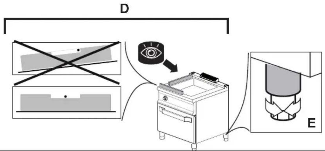
LEVELLING AND SECURING - see SECTION IMAGES - REFERENCES b).
Position in the work place (see operation and environmental limit conditions permitted), previously made suitable, of the appliance.
The tasks of levelling and securing include: adjustment of the appliance as a single independent unit.
Place a spirit level on the structure (detail D).
Adjust the levelling feet (detail E) according to the indications provided by the level.

Perfect levelling is achieved by adjusting level and feet on the width and depth of the appliance.
"SERIES" ASSEMBLY / see SECT. IMAGES - REF. c).
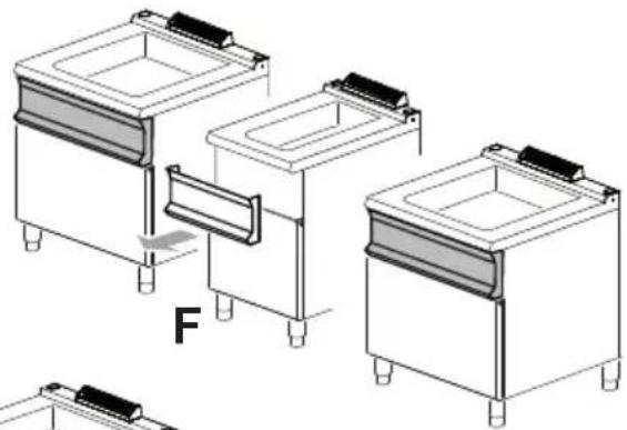
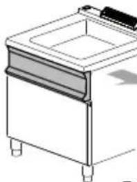
In the models provided, remove the knobs and unscrew the screws for the fixing of the panel (detail F).

Flammable walls / The minimum distance of the appliance from the side walls must be 10 cm
and from the rear wall must be 20 cm. If it is lower, insulate the walls close to the appliance with fireproof and / or insulating treatments.
To place the equipment adherent each other perfectly (part G). Level the equipment as described above (detail E). Remove the protective caps (part H2). Insert the screws in their housings and lock the two structures with the locking nuts (part H1-H3).
Repeat, if necessary, the sequence of leveling and fixing operations for the remaining equipment.
INTRODUCTION OF TERMINAL (OPTIONAL)) see SECT. IMAGES - REF. c) / In order to introduce the terminal, position it and fix it with the equipped screws provided (detail L1).
Once the described operations have been carried out, position again the panels and knobs of the different appliances in the respective housings.

POWER SUPPLY CONNECTIONS
4.

Before proceeding with the operations, see “General safety information”.

These operations must be performed by qualified and authorised operators, in accord-with the laws in force and using appropriate materials described.

The appliance is delivered without electric mains supply cable, without pipes for con-on to the water, drainage and networks.
ELECTRICAL CONNECTION
Electrical connection should be performed in compliance with the local regulations in force, only by authorised and competent personnel. In the first instance, examine the data shown on the technical data table of this manual, on the serial plate and on the electrical diagram. The envisaged connection is of the fixed type.

Connect the equipment to an overvoltage category III omnipolar device.

EARTHING / It is essential to earth the unit. To this purpose, it is necessary to connect to an ef-t earthing system the terminals ed with the symbols placed on the line-receiving terminal box. The earthing system should comply with the local law in force.
SPECIFIC WARNINGS / The electrical safety of this unit is assured only when it is correctly connected to an efficient earthing system as stated in the electrical local safety regulations in force; the Manufacturer declines any responsibility for the non-compliance with these safety regulations. It is necessary to verify this fundamental safety requisite and, in case of doubt, ask for an accurate testing of the system by professionally qualified personnel. The Manufacturer cannot be deemed responsible for any damages caused by the lack of unit earthing.

Never interrupt the earth wire (Yellow-Green).
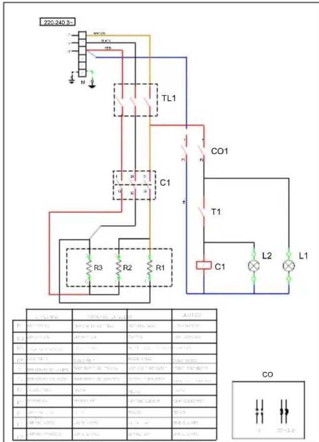
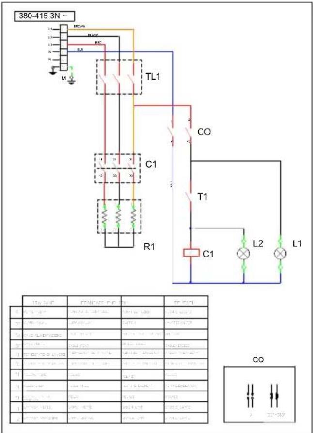
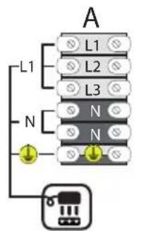
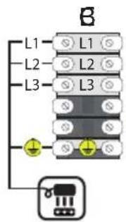
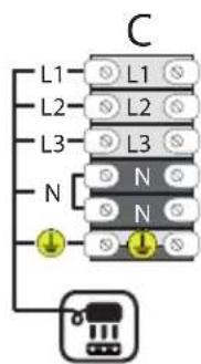
CONNECTION TO THE DIFFERENT ELECTRIC DISTRIBUTION NETWORKS / see SECT. IMAGES - REF. e)

If necessary, remove the terminal box protection panel located on the back of the machine.
The equipment is delivered to work with the voltage indicated on the technical label attached on the ap-
pliance. Any other connection is to be considered improper and therefore dangerous.
It is mandatory to respect the connection provided by the manufacturer, visible on the connection label near the terminal board.
It is forbidden to modify the wiring inside the equipment
ELECTRICAL CONNECTION OF THE CABLE TO THE TERMINAL
BOARD / Connect the power cable to the terminal board as described in: "Power supply connection" and indicated on the connection plate.. The diagram and the table (see Technical data) indicate the possible connections according to the mains voltage.
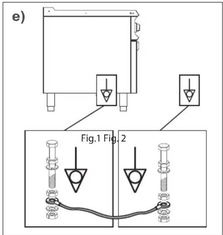
CONNECTION TO "EQUIPOTENTIAL" SYSTEM - see SECT. IMAGES - REF. f)
The protective earthing consists of a series of contrivances, which ensure the same earth potential in the electrical earths, thus preventing the same earths from being tensioned.
The earthing has the aim to ensure that the earths of the household appliances have the same potential of the earth. Earthing also makes the automatic intervention of the residual current device easier.
Protection earthing involves not only the electrical system, but also all the other systems and metallic parts of the building, including piping, beams, heating system and so on, so that the whole building turns out to be under safety conditions, also in case a lightning should hit the building.
Before proceeding with the operations, see “General safety info”.
The appliance must be included in an “Equipotential” system, which efficiency must be tested, according to the rules in force in the installation country.
The electrician preparing the general electrical system must guarantee a system in conformity with the regulations, for what concerns the direct and indirect contacts.
The electrician must connect all the different earths to the same potential, in order to achieve a good “Equipotential” earthing system in the area where the different appliances will be installed.
For what concerns the connection of the appliance to the room Equipotential system, use an electrical yellow/green cable, suitable to the power of the devices installed.
The appliance plate “Equipotential” is usually on its panel, near the system used for the connection; carry out the connection after having recognized the same plate (see schematic drawing for the correct location).
Connect an edge of the earth electric cable (the cable must be characterized by the double colour yellow/green) to the system used for the appliance “Equipotential” connection (see schematic drawing Fig. 1).
Connect the opposite edge of the earth electrical cable to the system used for the “Equipotential” connection of the area where the appliance will be installed (Fig. 2).
GENERAL WARNINGS

Operators have a duty to familiarise themselves adequately, using this manual before performing any intervention, adopting the specific safety requirements to make every kind of human-computer interaction safe.

Any technical modification that affects the operation or safety of the machine must only be carried out by the technical personnel of the manufacturer or by technicians that are formally authorised by the manufacturer. Failure to do so exempts the manufacturer from any liability for for any possible resulting modifications or damage.

Even after appropriate familiarisation, upon the first use of the appliance, in any case simulate a number of test operations to save more rapidly the main functions of the appliance, e.g. start-up, shut-down, etc.

The appliance is provided already tested by the manufacturer and fitted with the type of gas and electrical supply specified on the rating plate applies.
FIRST COMMISSIONING START
UP / Upon completion of the operations of positioning and connection to the power sources, perform a series of operations such as: 1. Cleaning away of the protective materials (oils, grease, silicones, etc.) inside and outside of the cooking chamber (see section 3 / Removal of protective materials).
- General checks and controls such as: Check opening of switches & network gate valves (water, electricity, gas when applicable); Checking of drains; Checking and monitoring of the external fumes/vapour extraction; Checking
and monitoring of the protection panels (all the panels must be fitted correctly).
DESCRIPTION OF STOP MODES

In stoppage conditions caused by faults and emergencies, in the event of imminent danger, it is mandatory to close all the locking devices on the supply lines upstream the appliance (Water-Gas-Ele).
STOPPAGE DUE TO FAULTY OPERATIONS
Safety component / STOP: In situations or circumstances which can be dangerous, a safety thermostat is triggered, automatically stopping heat generation. The production cycle is interrupted until the cause of the fault is resolved. RESTARTING: After the problem that triggered the safety thermostat is resolved, the authorised technician can restart the appliance by means of the specific controls.
COMMISSIONING FOR INITIAL START-UP

When commissioning the appliance and when starting it after a prolonged stop, it must be thoroughly cleaned to eliminate all residue of extraneous material (see chapter 3 / Removal of protective materials).
DAILY ACTIVATION
- Check the cleanliness and hygiene of the appliance.
- Make sure that the room exhaust system works properly.
- When necessary, plug the appliance into the appropriate socket.
- Open the network locks upstream the appliance (Gas - Water - Electric).
- Make sure that the water drain (if present) is not clogged.
Proceed with the operations described in "Starting production".

In order to free air in the pipes, open the network lock, turn the knob of the appliance while pressing it in the piezoelectric position, place a flame (match or the likes) on the pilot light and wait for it to ignite.
DAILY DECOMMISSIONG /
Upon completion of the operations described above:
- Close the network locks upstream the appliance (Water - Gas - Electric).
- Make sure that the drain cocks (if present) are "Closed".
- Check the cleanliness and hygiene of the appliance.
PROLONGED DECOMMISSIONING
/ In case of prolonged inactivity, perform all the procedures described for daily putting out of service and protect the parts most exposed to oxidation as indicated below:
- Use lukewarm water with a bit of
soap to clean the parts;
- Rinse the parts thoroughly, without use pressurised direct water or steam cleaners jets for cleaning operations;
- Dry the surfaces carefully using non-abrasive material;
- Wipe a non-abrasive cloth lightly soaked with food-safe Vaseline oil over all of the stainless steel surfaces in order to create a protective film.
For appliances with doors and rubber gaskets, leave the door slightly ajar to let it air out and spread protective talcum powder on the rubber gasket surfaces.
Periodically air the appliances and rooms.

To make sure that the appliance is in perfect technical conditions, arrange for service at least once a year by an authorised technician of the assistance service.

REPLACING COMPONENTS

PLEASE CALL TECHNICAL AUTHORIZED SERVICE AND READ THE TECHNICAL MANUAL

INSTRUCTIONS FOR USE
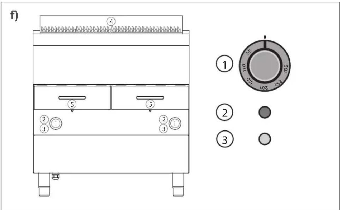
LOCATION OF MAIN COMPONENTS - see SECT. IMAGES - REF. f)
The layout of the figures is purely indicative and can undergo variations.
- Thermostat knob (see Knobs, keys and indicator light modes and functions).
2 / 3. Indicator light (see Knobs, keys and indicator light modes and functions).
4. Cooking grill.
5. Container for water and cooking oil/grease collection (for WGE7... models only)
6.OIL/GREASE collection drawer (for WGE9... models only) -REF. h fig.4.
KNOBS, GATE VALVES, BUTTONS AND INDICATOR LIGHT MODES AND FUNCTIONS / - see SECT. IMAGES - REF. f)
The layout of the keys in the figures is purely indicative and can be subject to variations.
① THERMOSTAT KNOB (ELE). It performs two different functions:
-
Adjusting cooking temperature.
-
Heating phase Start/Stop.
② GREEN INDICATOR LIGHT: The indicator is subordinated to use of the switch-on knob. Lighting of the indicator signals the operating phase.
③ YELLOW INDICATOR LIGHT: When present, the indicator is subordinated to use of the thermostat knob. Lighting of the indicator signals the heating phase.
STARTING PRODUCTION

Before proceeding with the operations, see chapters 2 and 5

Before proceeding with these operations, see "Daily activation".

When loading the product into the appliance and unloading it, there is a residual risk of being burnt; this risk can occur coming into unintentional contact with: hob - co-oking compartment - recipients or material processed.

For ideal cooking, pour 5.5 litres (WGE7... MODELS) or 6.5 litres (WGE9... MODELS) of water in each container. Refill in case of nee- ded.
SWITCHING ON/OFF / see SECT. IMAGES - REF. g)
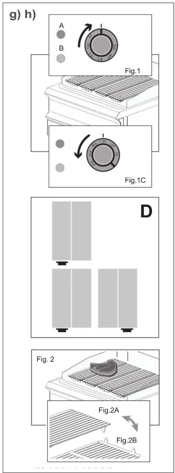
Do as follows to begin the cooking process: 1. Turn the knob to adjust the co-oking temperature (Fig. 1).
- When the green light is on it means
operation is in progress (Fig. 1A)
When the yellow light is on it means heating is in progress (Fig. 2 B).
- Turn the knob to "Zero" (Fig. 1C) to stop heat generation.

Cooking temperature is adjusted by means of the indications on the knob.

In the dual control (2 thermostat knobs) each knob operates on two grills (see layout D).
LOADING / UNLOADING THE PRO- DUCT / see SECT. IMAGES - REF. g)

Do not use pans or other containers to cook on the grill.

Wait for the correct temperature to be reached before placing food on the grill.

Do not use greasy and/or flammable condiments. Danger naked flames

FOR WGE9... MODELS, the bottom drawers must only contain water, they are not ASE OIL trays.
The grill can be used in two ways - see ILLUSTR sect. - REF g):
-
Method A - see Fig. 2A
-
Method B - see Fig. 2B - Lean food cooking
-
When the set temperature has been reached, place the product to be cooked directly on the grill (Fig. 2).
-
When cooking is over, remove the item from the appliance using the specific cookware and put it in a place prepared beforehand.
After the product has been unloaded, load it once again or else perform the operations described in "Deactivation".
DEACTIVATION / see SECT. IMAGES - REF. h)
At the end of the work cycle, turn the knobs on the appliance to "Zero".

The appliance must be cleaned regularly and every incrustation or food deposit removed. See ter: "Cleaning instructions".

If present, the indicator lights must be off at the end of the work cycle.
Check the cleanliness and hygiene of the appliance. See "Maintenance".
Close the network locks upstream the appliance (Gas - Water - Electric).

Wait for the temperature of the grill to cool off so that the operator is not burnt.
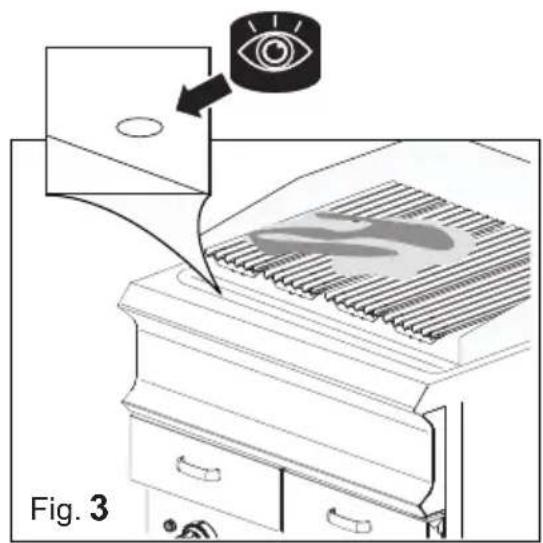
Check to make sure the drain piping has no obstructions (Fig.3).
Take out the drawers and clean it if necessary (Fig.4 see 4 Maintenance).

While draining burnt oils, the risk of being burnt remains. This risk can occur by unintentional act with oil processed at high temures.

Before operating, wait for the burnt oil to cool off.

The burnt oil collection container has a limited capacity. Keep an eye on the container fills while oil is emptied from the ing compartment.

Fill the recipient 3/4 to handle it safely. Once the recipient has reached 3/4 its capacity, remorom its seat, empty it and put it in place.

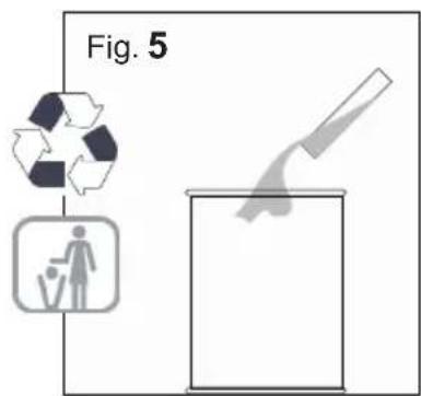
Empty the container in compliance with waste disposal procedures in force in the try where the appliance is used reposition the emptied recipient housing (Fig. 5).

MAINTENANCE
OBLIGATIONS - PROHIBITIONS - ADVICE

Before proceeding with the operations, see chapters 2 and 5

If the appliance is connected to a flue, the exhaust pipe must be cleaned according to that forensic regulatory provisions of country (contact your installer for nation).

The appliance is used to prepare food products. Keep the appliance and the surrounding area con-ly clean. Failure to keep the ap-ice in ideal hygienic conditions cause it to deteriorate quickly and the dangerous situations.

Filth deposit built up near heat sources can burn during normal use of the appliance and create erous situations. The appliance be cleaned regularly and every in-ation or food deposit removed.

The chemical effect of salt and/or vinegar or other acid substances can in the long run cause the insi-the hob to corrode during cooking. The end of the cooking cycle of such stances, the appliance must be ded thoroughly with detergent, dantly rinsed and carefully dried.

Be careful not to damage stainless steel surfaces. No not use sive products, abrasive material
or sharp tools.

The liquid detergent for cleaning the hob must have certain chemical features: pH greater than 12, without chlorides/ammonia, viscosity and density similar to water. Use non-aggressive products for cleaning the inside and outside of the appliance (use detergents on the market for cleaning steel, glass and enamel).

Carefully read the indications carried on the labels of the products used. Wear protective equipment suitable for the operations to be performed (see the protective equipment carried on the package label).

In the event of prolonged inactivity, besides disconnecting the supply lines, you must thoroughly clean all the inside and outside parts of the appliance.

Wait for the temperature of the appliance and all its parts to cool off, so that the operator is not burnt.
DAILY CLEANING


Wait for the temperature of the grill to cool off so that the operator is not burnt.


Do not use pressurised direct water or steam cleaners jets for cleaning operations.
1- Lift the cooking grill, and using a non-abrasive sponge, clean the entire surface thoroughly with soapy lukewarm water.
2- Rinse the parts and carefully dry all the surfaces using non-abrasive material;
Afterwards dry it thoroughly and put it back in place.
3- Remove, drain and carefully wash the
drawers, after the cleaning operations dry it and put it back in its seat.
4- Carefully reposition all of the parts removed in their housing, making sure not to invert the assembly sequence.
If necessary, repeat the operations described above for a new cleaning cycle.
GRILL: For cleaning operation use a non-abrasive sponge and a neutral liquid detergent. Clean the grill with a moist cloth.

Humidity residue deposited on the grill can damage the appliance and cause the grills to wear quickly.

In order to eliminate all humidity residue on the grills thus avoiding quick wear, once routine cleaning been finished, turn the appliance on approximately 10'.
CLEANING FOR PROLONGED DEACTIVATION /
To conclude the operations see chap. 5 / Operations for commissioning / Prolonged decommissioning
Air out the appliances and rooms regularly.
SUMMARISED TABLE / OPERATION - FREQUENCY

Before proceeding with the operations, see chapter 2 “Duties and Qualification”

Should a problem occur, the generic operator performs the first search and, if qualified, eliminate cause of the problem and re-ss the appliance correctly.

If the problem cannot be resolved, turn the appliance off, disconnect it from the electrical s and shut all the supply valves. I contact authorized customer ce.

The authorized maintenance te-
chnician intervenes when the generic operator was not able to pinpoint the cause of the problem, or whenever restoration of correct operation of the appliance entails executing operations for which the generic operator is not qualified.

If the power cable is damaged, contact the authorised technical assistance service to have it replaced.
EN
| OPERATION FREQUENCY | ||
 | Cleaning parts in contact with foodstuff | Daily |
| Cleaning grill Daily | ||
 | Cleaning at commissioning Upon arrival after installation | |
| Checking thermostat Yearly | ||
| Checking internal parts Every 6 months / Yearly | ||
TROUBLESHOOTING

Whenever the appliance does not work properly, try to solve the less serious problems using this table.
| FAULT POSSIBLE CAUSE INTERVENTION | ||
| The appliance does not turn on. | · The master switch is not connected.· The residual current device or circuit breaker has tripped. | · Connect the master switch.· Call technical authorized service |
| The cooking compartment is stained. | · Quality of the water.· Ineffective detergent.· Insufficient rinsing. | · Filter the water (Call technical authorized service and read the Technical Manual).· Use the recommended detergent.· Rinse once again. |
| The light indicators do not turn on. | · The master switch is not connected.· The residual current device or circuit breaker has tripped. | · Connect the master switch.· Call technical authorized service |
| The orange lamp remains turned off | · Working thermostat is broken. | · Call technical authorized service |
| Temperature is not adjustable/ Equipment doesn’t heat | · Working thermostat is broken. | · Call technical authorized service |
| Surface working temperature is not enough for co-oking / Orange lamp turn on and off continuously | · No water into drawer | · Refill the drawer. |

If the problem cannot be resolved, turn the appliance off, disconnect it from the electrical mains and shut all the supply valves. Then contact authorized customer service.
DEACTIVATION AND SCRAPPING OF APPLIANCE
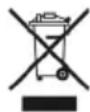
Obligation of disposing of materials using the legislative procedure in force in the counhere the appliance is scrapped
In compliance with Directives (see n. 0.1 Section), relating to the reduction of use of hazardous substances in electrical and electronic equipment, as well as waste disposal. The symbol of the barred waste bin carried on the appliance or its packaging indicates that the product at the end of its useful life it must be disposed of separately from other waste.
Differentiated waste collection of this appliance at the end of its life is organised and implemented by the manufacturer. The user who wishes to get rid of this appliance must contact the manufacturer and follow the instructions received to separately dispose of the appliance at the end of its life. An appropriate collection and dispatching of exhausted appliances to environmentally compatible recycling, treatment and disposal plants helps to prevent damaging effects on health and environment and also guarantees that the component parts of exhausted appliances are effectively recycled or reused. Holders of exhausted appliances who dispose of them illegally will be prosecuted. Specialised personnel is in charge of deactivation and scrapping of the appliance.

The decommissioning and dismantling of the appliance must be carried out by qualified personnel, either mechanical or electrical, that must wear appropriate personal protective equipment such as protective clothing appropriate to the operations to be performed, protective gloves, safety shoes, head gear and goggles.

Before commencing dismantling of the appliance, ensure around the appliance a space that is large enough and arranged in such a way as to allow all movements without risk.
The following are necessary:
- Disconnect the power supply.
- Disconnect the appliance from the mains.
- Remove the electrical cables exiting the appliance.
- Close the water inlet tap (mains valve) from the mains supply.
- Disconnect and remove the pipes from the appliance water system.
- Disconnect and remove the grey water discharge pipe.

After this operation, a wet area around the appliance form and therefore, before nuing with operations, dry wet areas.
After restoring the operational area as described:
- Remove the protective panels.
- Disassemble the appliance in its main parts.
- Separate the parts of the appliance according to their nature (e.g. metals, electrical parts etc.) and deliver them to recycling centres.
WASTE DISPOSAL

During operation and maintenance, do not disperse pollutants (oils, grease, etc.) into the environment and perform differentiated waste disposal depending on the composition of the different materials and in compliance with relevant laws in force.
Illegal waste disposal will be prosecuted by laws in force in the territory where the violation has been ascertained.
TABLE DES MATIÈRES
1- 2. INFORMATIONS GÉNÉRALES ET SUR LA SECURITE
3. MISE EN PLACE ET MANUTENTION
4. RACCORDEMENTSAUX SOURCES D'ENERGIE
5. OPÉRATIONS POUR LA MISE EN SERVICE
- REMPLACEMENT DES COMPOSANTS
- INSTRUCTIONS POUR L'UTILISATION
8.MAINTENANCE - ÉLIMINATION
- DONNÉES TECHNIQUES / IMAGES
DESCRIPTION DES PICTOGRAMMES
CONSERVATION DU DOCU-
- Grille support panier
OBLIGATIONS - INTERDICATIONS - CONSEILS - RECOMMANDATIONS

SÉCURITÉ POUR LA MANUTENTION

EMPLACEMENT DES PRINCI-PAUX COMPOSANTS - V. SECT. ILLUSTRATIONS - RÉF. f).
ALLUMAGE / ARRÊT - v. sect. ILL. - RÉFÉRENCE g)
OBLIGATIONS - CONSEILS - RECOMMANDATIONS

ALGEMENE WAARSCHUWIN- GEN
STOP WEGENS STORING WER-KING.
Veiligheidscomponent / STOP:
USYTUOWANIE GŁÓWNYCH KOMPONENTÓW – ZOB. DZ. ILUSTRACJE - ODN. f).
TILKOBLING TIL STR∅MFOR- SYNING
RATED SUPPLY VOLTAGE /
A) 230 V \~ 1N 50/60 Hz. N.B.: The power absorbed with 220 V \~ 1N 50/60 Hz is about 8% lower. The power absorbed with 240 V \~ 1N 50/60 Hz is about 8% lower. B) 400 V \~ 3N 50/60 Hz. N.B.: The power absorbed with 380 V \~ 3N 50/60 Hz is about 8% lower. The power absorbed with 415 V \~ 3N 50/60 Hz is about 8% lower.
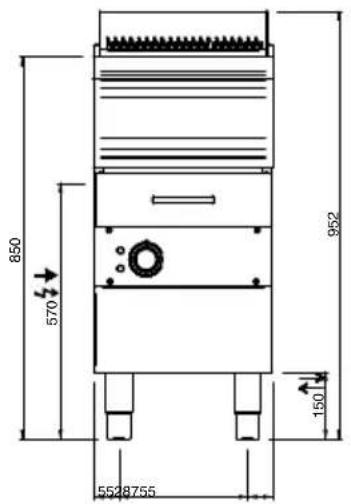
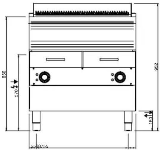
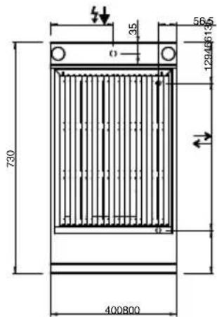
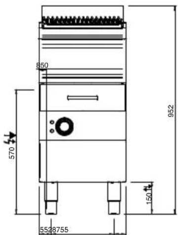
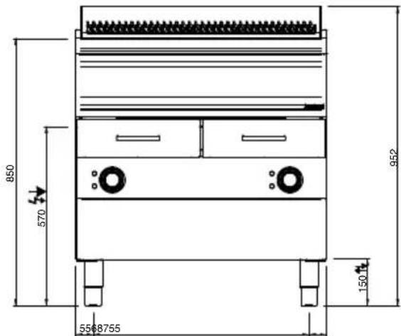
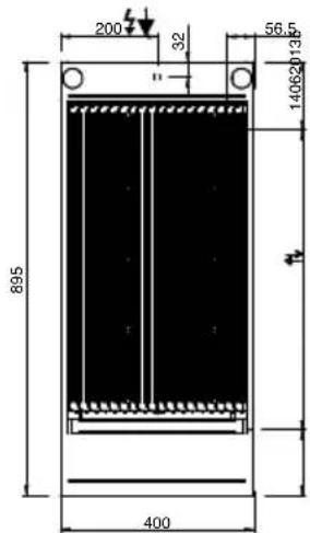
ON CUPBOARD MOD.700
LEGENDA SIMBOLI / LEGEND

INGRESSO ACQUA / WATER INLET ∅ M 1/2"

ATTACCO EQUIPOTENZIALE / EQUIPOTENTIAL

ALIMENTAZIONE ELETTRICA / POWER SUPPLY

SCARICO ACQUA / OLII WATER / OILS DRAIN

REGOLAZIONE PIEDINI / FEET ADJUSTMENT (h 0/+50) / TOP VERSION (h 0/+5)
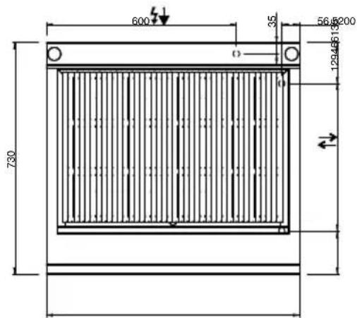
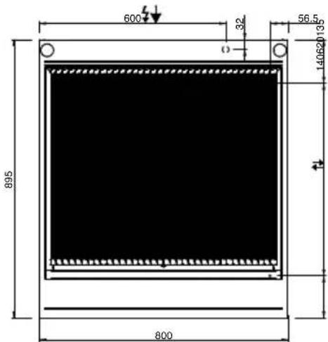
ON CUPBOARD MOD.900

INGRESSO ACQUA / WATER INLET ∅ M 1/2"

ATTACCO EQUIPOTENZIALE / EQUIPOTENTIAL

ALIMENTAZIONE ELETTRICA / POWER SUPPLY

SCARICO ACQUA / OLII
WATER / OILS DRAIN

REGOLAZIONE PIEDINI /
FEET ADJUSTMENT (h 0/+50)
/TOP VERSION (h 0/+5)
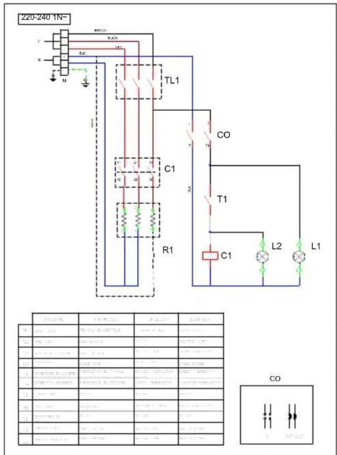
SCHEMA ELETTRICO - WIRING DIAGRAM
THE PRESENT MANUAL IS PROPERTY OF THE MANUFACTURER. ANY REPRODUCTION, EVEN PARTIAL, IS PROHIBITED. IL PRESENTE MANUALE È DI PROPRIETÀ DEL FABBRICANTE E OGNI RIPRODUZIONE ANCHE PARZIALE È VIETATA.
INSTALLAZIONE / INSTALLATION
a)
flowchart
graph TD
    A["Building with ABC"] --> B{Eye Detection}
    B -->|Yes| C["Forward to person, handbag, and box"]
    B -->|No| D["Forward to forklift, handbag, and box"]
    C --> E["User in crane, device, and box"]
    D --> F["User in handbag, device, and box"]
    E --> G["User in handbag, device, and box"]
    F --> H["User in handbag, device, and box"]
    G --> I["OK!"]
    H --> J["OK!"]
    I --> K["Error Handling"]
    J --> L["Error Handling"]
    K --> M["Error Handling"]
    L --> N["Error Handling"]
    M --> O["Error Handling"]
    N --> P["Error Handling"]
b)
THE PRESENT MANUAL IS PROPERTY OF THE MANUFACTURER. ANY REPRODUCTION, EVEN PARTIAL, IS PROHIBITED. IL PRESENTE MANUALE È DI PROPRIETÀ DEL FABBRICANTE E OGNI RIPRODUZIONE ANCHE PARZIALE È VIETATA.
c)
natural_image
Technical line drawing of a multi-compartment kitchen appliance with mounting legs and a handle, showing assembly steps (no text or symbols)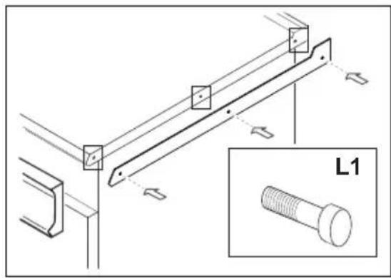
natural_image
Line drawing of a stainless steel kitchen appliance with a side panel and handle (no text or symbols)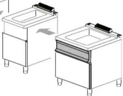
natural_image
Technical line drawing of two identical kitchen appliances with side legs and a central drawer (no text or symbols)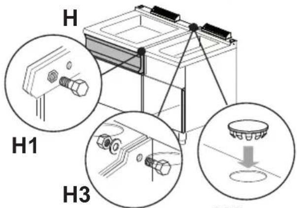
H2
d)
A: FASI 220/240 V \~ 1N 50-60 HZ
B: FASI 220/240 V \~ 3 50-60 HZ
C: FASI 380/415 V \~ 3N 50-60 HZ

USO / USER
THE PRESENT MANUAL IS PROPERTY OF THE MANUFACTURER. ANY REPRODUCTION, EVEN PARTIAL, IS PROHIBITED. IL PRESENTE MANUALE È DI PROPRIETÀ DEL FABBRICANTE E OGNI RIPRODUZIONE ANCHE PARZIALE È VIETATA.
natural_image
Diagram showing a device with an eye icon interacting with a grid-patterned surface, labeled Fig. 3 (no text or symbols on the diagram itself)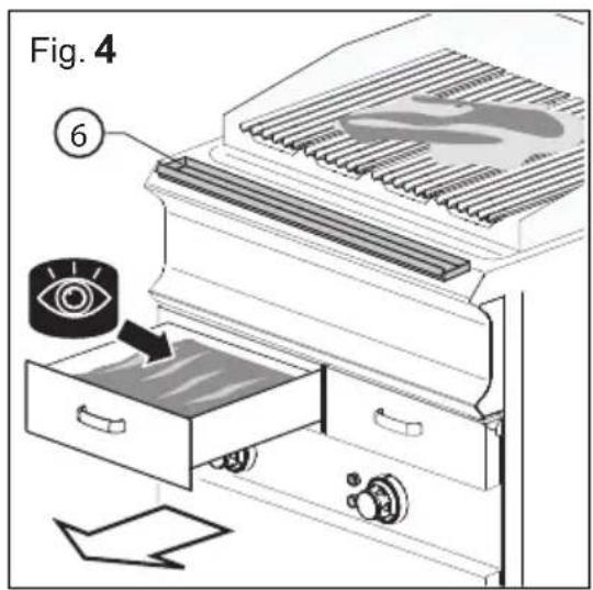
- RISCHIO RESIDUO DI USTIONE PER FUORIU- SCITA MATERIALE /
- Prohibition indications.
- Obligation indications.
- GENERAL AND SAFETY INFORMATION
- PURPOSE OF THE DOCUMENT /
- OPERATOR TRAINING
- PRE-ARRANGEMENTS DEPENDING ON CUSTOMER /
- CONTENTS OF THE SUPPLY /
- ALLOWED OPERATING
- DUTIES AND QUALIFICATIONS REQUIRED OF OPERATORS
- WORK AREAS AND HAZARDOUS ZONES /
- The following are also danger zones /
- EQUIPMENT REQUIRED FOR INSTALLATION /
- INDICATION ON RESIDUAL
- RESIDUAL RISK OF ELECTROCUTION/
- RESIDUAL RISK OF BUR- NING / This risks remains
- RESIDUAL RISK OF BURNS DUE TO LEAKING OF MATERIAL / This risks remains
- RESIDUAL RISK OF CRU- SHING LIMBS / This risk exi- sts where there is accidental
- RESIDUAL RISK OF EXPLOSIONS /
- RESIDUAL RISK OF FIRE /
- OBLIGATIONS - PROHIBITIONS - ADVICE
- HANDLING SAFETY /
- HANDLING - TRANSPORTATION / - see SECT. IMAGES - REF. a).
- DISPOSAL OF PACKAGING
- CLEANING AT COMMISSIONING /
- LEVELLING AND SECURING - see SECTION IMAGES - REFERENCES b).
- "SERIES" ASSEMBLY / see SECT. IMAGES - REF. c).
- POWER SUPPLY CONNECTIONS
- ELECTRICAL CONNECTION
- CONNECTION TO THE DIFFERENT ELECTRIC DISTRIBUTION NETWORKS / see SECT. IMAGES - REF. e)
- ELECTRICAL CONNECTION OF THE CABLE TO THE TERMINAL
- CONNECTION TO "EQUIPOTENTIAL" SYSTEM - see SECT. IMAGES - REF. f)
- GENERAL WARNINGS
- FIRST COMMISSIONING START
- DESCRIPTION OF STOP MODES
- STOPPAGE DUE TO FAULTY OPERATIONS
- COMMISSIONING FOR INITIAL START-UP
- DAILY ACTIVATION
- DAILY DECOMMISSIONG /
- PROLONGED DECOMMISSIONING
- Periodically air the appliances and rooms.
- LOCATION OF MAIN COMPONENTS - see SECT. IMAGES - REF. f)
- KNOBS, GATE VALVES, BUTTONS AND INDICATOR LIGHT MODES AND FUNCTIONS / - see SECT. IMAGES - REF. f)
- STARTING PRODUCTION
- SWITCHING ON/OFF / see SECT. IMAGES - REF. g)
- LOADING / UNLOADING THE PRO- DUCT / see SECT. IMAGES - REF. g)
- DAILY CLEANING
- CLEANING FOR PROLONGED DEACTIVATION /
- SUMMARISED TABLE / OPERATION - FREQUENCY
- TROUBLESHOOTING
- DEACTIVATION AND SCRAPPING OF APPLIANCE
- WASTE DISPOSAL
- TABLE DES MATIÈRES
- DESCRIPTION DES PICTOGRAMMES
- CONSERVATION DU DOCU-
- OBLIGATIONS - INTERDICATIONS - CONSEILS - RECOMMANDATIONS
- SÉCURITÉ POUR LA MANUTENTION
- EMPLACEMENT DES PRINCI-PAUX COMPOSANTS - V. SECT. ILLUSTRATIONS - RÉF. f).
- ALLUMAGE / ARRÊT - v. sect. ILL. - RÉFÉRENCE g)
- OBLIGATIONS - CONSEILS - RECOMMANDATIONS
- ALGEMENE WAARSCHUWIN- GEN
- STOP WEGENS STORING WER-KING.
- USYTUOWANIE GŁÓWNYCH KOMPONENTÓW – ZOB. DZ. ILUSTRACJE - ODN. f).
- TILKOBLING TIL STR∅MFOR- SYNING
- RATED SUPPLY VOLTAGE /
- ON CUPBOARD MOD.700
- LEGENDA SIMBOLI / LEGEND
- ON CUPBOARD MOD.900
- INSTALLAZIONE / INSTALLATION
- USO / USER
Brand : MBM
Model : WGE74
Category : Grill plate