SSVM 40 B2 - Fan SILVERCREST - Free user manual and instructions
Find the device manual for free SSVM 40 B2 SILVERCREST in PDF.

| Product type | Pedestal fan |
| Brand | SilverCrest |
| Model | SSVM 40 B2 |
| Blade diameter | 40 cm |
| Input voltage | 220-240 V~, 50/60 Hz |
| Power consumption | 45 W |
| Maximum volumetric flow rate | 70.52 m³/min |
| Sound power level | 65.13 dB(A) |
| Maximum air velocity | 2.94 m/s |
| Number of speeds | 3 (I, II, III) + stop (0) |
| Oscillation | Yes, on/off by button |
| Height adjustment | Yes, by button on tube |
| Tilt adjustment | Yes, by button |
| Protective grille | Front and rear, clip-on |
| Use | Dry indoor only |
| Warranty | 3 years |
| Article number (IAN) | 384798_2107 |
| After-sales service France | 0800 904 879 |
| After-sales service Belgium | 0800 710 11 |
| Package contents | Motor unit, base, weight, tube, grilles, blade, screws |
| Accessories required for assembly | Phillips screwdriver |
Frequently Asked Questions - SSVM 40 B2 SILVERCREST
User questions about SSVM 40 B2 SILVERCREST
0 question about this device. Answer the ones you know or ask your own.
Ask a new question about this device
Download the instructions for your Fan in PDF format for free! Find your manual SSVM 40 B2 - SILVERCREST and take your electronic device back in hand. On this page are published all the documents necessary for the use of your device. SSVM 40 B2 by SILVERCREST.
USER MANUAL SSVM 40 B2 SILVERCREST
STANDVENTILATOR / PEDESTAL FAN / VENTILATEUR SUR PIED SSVM 40 B2
DE AT CH
STANDVENTILATOR
Operation and safety notes
FR BE
VENTILATEUR SUR PIED
GB/IE Operation and safety notes Page 13
F

Warnings and symbols used Page 14
Introduction Page 14
Intended use....Page 14
Scope of delivery....Page 14
Description of parts ...... Page 15
Technical data Page 15
Safety instructions....Page 16
Before use ...... Page 18
Unpacking Page 18
Assembly Page 18
Height adjustment Page 18
Tilt adjustment....Page 18
Operation....Page 19
Fan speed Page 19
Oscillation Page 19
Cleaning and care Page 19
Storage Page 19
Disposal Page 19
Warranty Page 20
Warranty claim procedure....Page 20
Service Page 20
| Warnings and symbols usedThe following warnings are used in this user manual and on the packaging: | |||
 | DANGER! This symbol in combination with the signal word “Danger” marks a high-risk hazard that if not prevented could result in death or serious injury. |  | NOTE: This symbol in combination with “Note” provides additional useful information. |
 | Danger - Risk of electric shock! | ||
 | WARNING! This symbol in combination with the signal word “Warning” marks a medium-risk hazard that if not prevented could result in death or serious injury. |  | Only use the product in dry indoor rooms. |
 | Do not put fingers through the grille. | ||
 | CAUTION! This symbol in combination with the signal word “Caution” marks a low-risk hazard that if not prevented could result in minor or moderate injury. |  | CE mark indicates conformity with relevant EU directives applicable for this product. |
PEDESTAL FAN
Introduction
We congratulate you on the purchase of your new product. You have chosen a high quality product. The instructions for use are part of the product. They contain important information concerning safety, use and disposal. Before using the product, please familiarise yourself with all of the safety information and instructions for use. Only use the product as described and for the specified applications. If you pass the product on to anyone else, please ensure that you also pass on all the documentation with it.
Intended use
This product is intended to produce a cooling airflow. Any other use not mentioned in these instructions may cause a damage to the product or create a serious risk of injury.
This product is only intended for private household use, not for commercial purposes.
The manufacturer accepts no liability for damages caused by improper use.
- Scope of delivery
■ Unpack the product. Remove the transport locks. Accessory needed: Pair of scissors (Fig. B)
■ After unpacking the product, check if all parts are complete and in good condition. Remove all packing materials (including protective foils) before use.
1 Motor unit (with upper pole and 4 lock screws)
1 Base
1 Base weight
1 Extension pole and lower pole (with washer and L-shaped bolt)
1 Front grille (with lock nut and lock screw)
1 Rear grille
1 Blade (with lock screw)
NOTE: Various removable components are delivered pre-assembled (see "Description of parts").
• Description of parts
Before reading, unfold the page containing the illustrations and familiarise yourself with all the functions of the product.
Fig. A
| 1 | Blade |
| 2 | Rear grille |
| 3 | Grille handle |
| 4 | Motor shaft |
| 5 | Speed control knob (0, I, II, III) |
| 6 | Oscillation control knob |
| 7 | Power cord with power plug |
| 8 | *Screw and nut |
| 9 | *Knob (tilt adjustment) |
| 10 | Motor unit (with upper pole) |
| 11 | *Lock screw (motor bracket) |
| 12 | *Height adjustment knob |
| 13 | Extension pole |
| 14 | Base |
| 15 | Base weight |
16 *Washer
17 *L-shaped bolt
18 *Lock screw (M5 x 8 mm) (x 4) (rear grille)
19 *Lock screw (M4 x 8 mm) (blade)
20 Grille clips (x 5)
21 * Lock nut and lock screw (M2.5 x 10 mm) (grille)
22 Front grille
23 Grille hanger
* pre-assembled
- Technical data
Input voltage: 220-240 V \~50-60 Hz
Power consumption: 45 W
Description Symbol Value Unit
| Maximum fan flow rate | F | 70.52 m | ^3 /min |
| Fan power input | P | 44.1 | W |
| Service value | SV | 1.60 | (m ^3 /min)/W |
| Standby power consumption | P_SB | 0.0 | W |
| Fan sound power level | L_WA | 65.13 | dB(A) |
| Maximum air velocity | C | 2.94 | meters/sec |
| Measurement standard for service value | IEC 60879:1986 (corr. 1992) | ||
| Contact details for obtaining more information | OWIM GmbH & Co. KGStiftsbergstraße 174167 NeckarsulmGERMANYwww.owim.com | ||

Safety instructions
BEFORE USING THE PRODUCT, PLEASE FAMILIARISE YOURSELF WITH ALL OF THE SAFETY INFORMATION AND INSTRUCTIONS FOR USE! WHEN PASSING THIS PRODUCT ON TO OTHERS, PLEASE ALSO INCLUDE ALL THE DOCUMENTS!
In the case of damage resulting from non-compliance with these operating instructions the warranty claim becomes invalid! No liability is accepted for consequential damage! In the case of material damage or personal injury caused by incorrect handling or non-compliance with the safety instructions, no liability is accepted!
Children and persons with disabilities
⚠️DANGER! Risk of
suffocation! Never leave children unsupervised with the packaging material.
The packaging material represents a danger of suffocation. Children frequently underestimate the dangers. Always keep children away from the packaging material.
This product can be used by children aged from 8 years and above and persons with reduced physical, sensory or mental capabilities, or lack of experience and knowledge if they have been given supervision or instruction concerning use of the product in a safe way and understand the hazards involved.
Cleaning and user maintenance shall not be made by children without supervision.
Children shall not play with the product.
Electrical safety
⚠ WARNING! Risk of injury!
Switch the product off and disconnect it from the power supply before cleaning work and when not in use.
⚠ WARNING! Risk of electric shock! Ensure the rated voltage shown on the rating label corresponds with the voltage of the power supply.
⚠ WARNING! Risk of electric shock! If the supply cord is damaged, it must be replaced by the manufacturer, its service agent or similarly qualified persons in order to avoid a hazard.
Operation
■ Only use the product in dry indoor rooms.
■ Protect the product, its power cord and power plug against dust, direct sunlight, dripping and splashing water.
⚠️CAUTION! Risk of injury!
Ensure that the fan is switched off from the supply mains before removing the guard.
⚠️CAUTION! Risk of injury!
Never use the product without the safety grille or with a damaged safety grille.
⚠️CAUTION! Risk of injury!
During use, keep hands, hair, clothing and utensils away from the safety grille to avoid injuries and damage of the product.
Before use
Unpacking
■ Remove the packaging. Check if the product is damaged.
Assembly
■ Accessory needed: Cross head screwdriver
■ Number of persons needed for assembly: 1 adult
Fig. Step
| C | 1. Turn the extension pole 13 upside down so that the L-shaped bolt 17 is directed upwards.2. Remove the L-shaped bolt 17 and the washer 16 from the extension pole 13.3. Place the base 14 and the base weight 15 on the extension pole 13.4. Fasten the washer 16 and the L-shaped bolt 17. |
| D | 1. Turn the assembled parts from the previous assembly step upside down. Place the base 14 on the floor.2. Loosen the lock screw 11 from the extension pole 13.3. Place the motor unit's 10 upper pole on the extension pole 13. Align the hole on the back side. Tighten the lock screw (motor bracket) 11. |
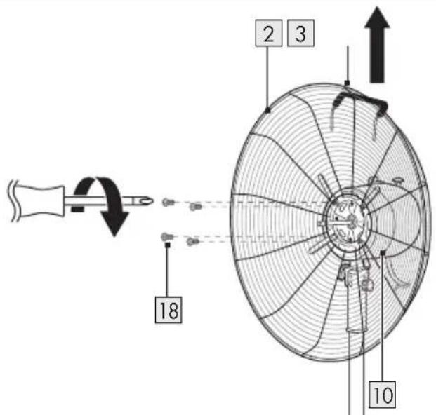
| E | Remove the lock screws (M5 x 8 mm) (x 4) (rear grille) 18 from the motor unit 10. |
| F | 1. Align the grille handle 3 upwards and to the rear. Attach the rear grille 2 to the motor unit (with upper pole) 10.2. Tighten with the 4 lock screws 18. |
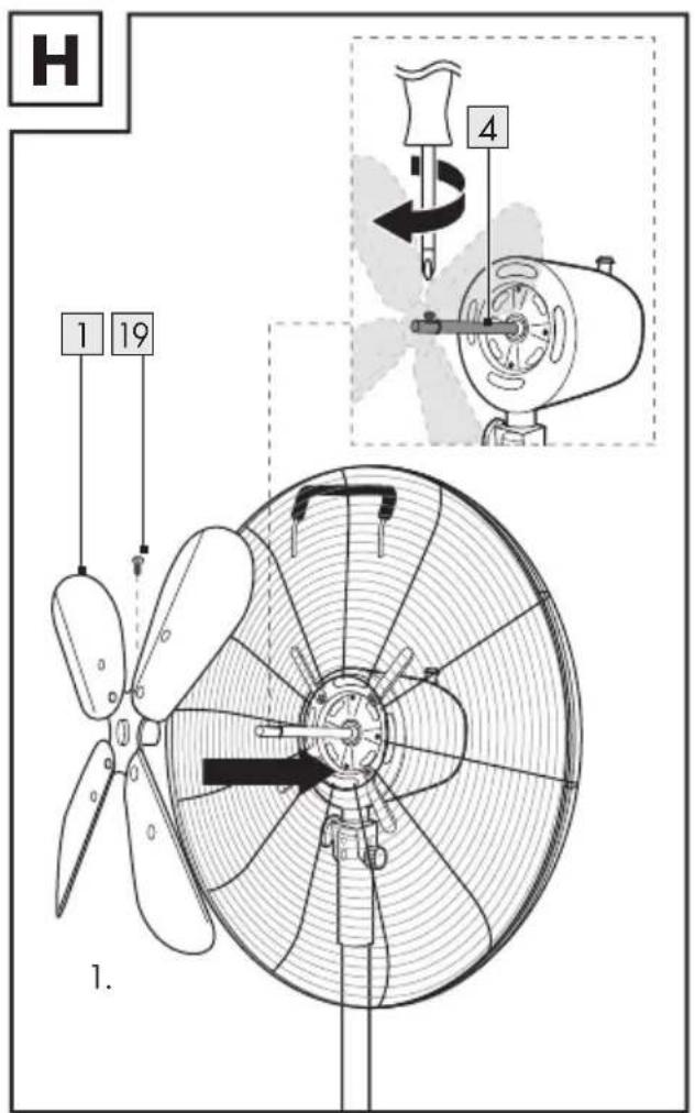
| G | Point the groove on the motor shaft 4 upwards. |
Fig. Step
| H | 1. Loosen the lock screw 19 from the blade 1 (the lock screw is pre-assembled on the blade's screw thread).Place the blade on the motor shaft 4 (the blade's rear with the lock screw is facing the motor unit (with upper pole) 10). |
| It | 2. Tighten the lock screw (M4 x 8 mm) (blade) 19. |
-
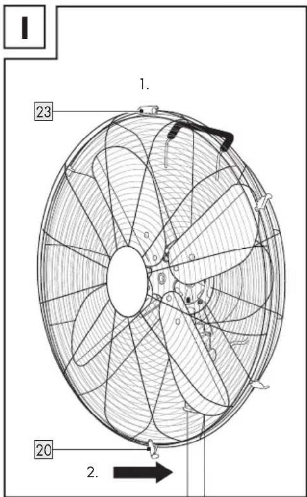
Open the grille clips (x 5) 20 on the front grille 22.
-
Remove the lock nut and lock screw (M2.5 x 10 mm) (grille) 21 from the front grille 22.
-
Hang the grille hanger 23 of the front grille 22 on the rear grille 2.
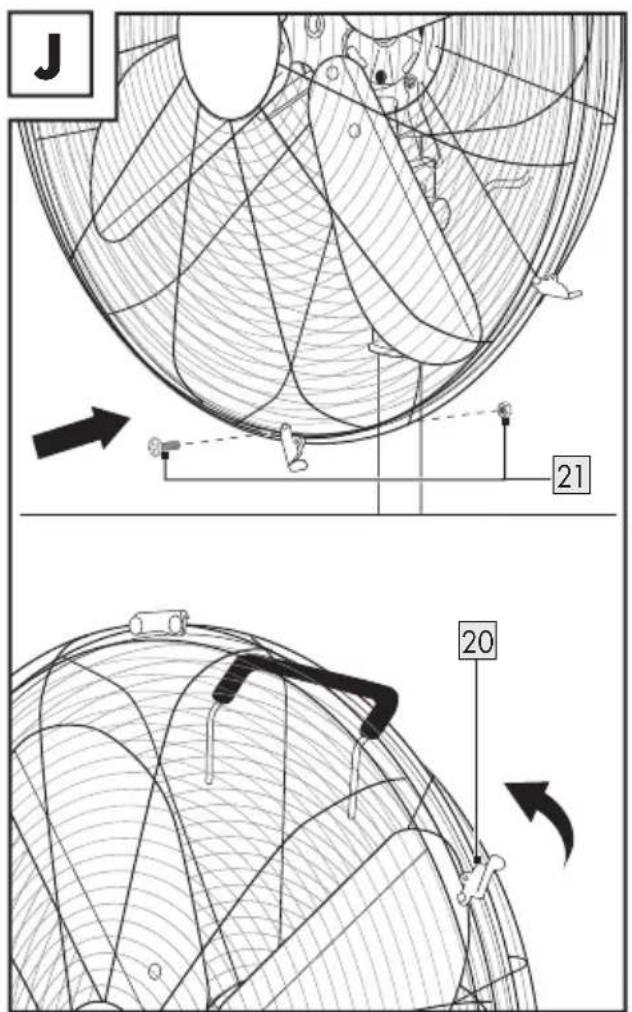
NOTE: The grille clips (x 5) 20 must fit over the frame of the rear grille 2.
Insert the lock screw 21. Fasten the lock nut 21. Close the grille clips (x 5) 20 at the grille frame.
● Height adjustment
■ Loosen the height adjustment knob 12 (positioned on the extension pole 13 ) in a counter-clockwise direction.
■ Adjust the length of the extension pole 13.
- Tighten the height adjustment knob 12 in a clockwise direction.
- Tilt adjustment
■ Loosen the knob (tilt adjustment) 9.
■ Adjust the tilt angle manually.
■ Tighten the knob (tilt adjustment) 9 again.
Do not perform the tilt adjustment when the product is in operation.
NOTE: The screw and the nut 8 are intended for guiding the tilt adjustment. Neither remove the screw not the nut when adjusting the tilt angle.
Operation
- Place the product on a flat, stable ground.
■ Connect the power plug 7 to a suitable socket-outlet.
Fan speed
- Rotate the speed control knob 5 to turn the product on/off and to select the fan speed setting:
Position Function
■ Adjust the oscillation control knob 6:
Knob position
Oscillation during operation
Pulled out Off
Pushed in On
● Cleaning and care
Before cleaning: Rotate the speed control knob 5 to the 0 position. Disconnect the power plug 7 from the socket-outlet.
■ Clean the product with a slightly moistened cloth.
Do not allow any water or other liquids to enter the motor unit 10.
WARNING! Do not immerse the electrical parts of the product in water or other liquids. Never hold the product under running water.
Both front and rear grille 2 22 must not be removed under any circumstances.
- Clean the grilles 2 22 with a vacuum cleaner and a damp cloth only.
Storage
- When not in use, store the product in its original packaging.
■ Store the product in a dry, secure location away from children.
Disposal
The packaging is made entirely of recyclable materials, which you may dispose of at local recycling facilities.
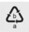
Observe the marking of the packaging materials for waste separation, which are marked with abbreviations (a) and numbers (b) with following meaning: 1–7: plastics / 20–22: paper and fibreboard / 80–98: composite materials.

The product and packaging materials are recyclable, dispose of it separately for better waste treatment. The Triman logo is valid in France only.

Contact your local refuse disposal authority for more details of how to dispose of your worn-out product.
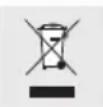
To help protect the environment, please dispose of the product properly when it has reached the end of its useful life and not in the household waste. Information on collection points and their opening hours can be obtained from your local authority.
Warranty
The product has been manufactured to strict quality guidelines and meticulously examined before delivery. In the event of product defects you have legal rights against the retailer of this product. Your legal rights are not limited in any way by our warranty detailed below.
The warranty for this product is 3 years from the date of purchase. The warranty period begins on the date of purchase. Please keep the original sales receipt in a safe location. This document is required as your proof of purchase.
Should this product show any fault in materials or manufacture within 3 years from the date of purchase, we will repair or replace it – at our choice – free of charge to you. This warranty becomes void if the product has been damaged, or used or maintained improperly.
The warranty applies to defects in material or manufacture. This warranty does not cover product parts subject to normal wear, thus possibly considered consumables (e.g. batteries) or for damage to fragile parts, e.g. switches, rechargeable batteries or glass parts.
● Warranty claim procedure
To ensure quick processing of your case, please observe the following instructions:
Please have the till receipt and the item number (IAN 384798_2107) available as proof of purchase.
You will find the item number on the rating plate, an engraving, on the front page of the instructions for use (bottom left), or as a sticker on the rear or bottom of the product.
If functional or other defects occur, please contact the service department listed either by telephone or by e-mail.
You can return a defective product to us free of charge to the service address that will be provided to you. Ensure that you enclose the proof of purchase (till receipt) and information about what the defect is and when it occurred.
Service
GB Service Great Britain
Tel.:08000569216
E-Mail:owim@lidl.co.uk
IE Service Ireland
Tel.:1800200736
E-Mail:owim@lidl.ie
CE
| Regulator-position | Oscillation under drift |
Udtrukket Fra
Indtrykket Til
Pooblaščeni serviser:
OWIM GmbH & Co. KG
Stiftsbergstraße 1
74167 Neckarsulm
NEMČIJA