
XFE 15 150 18.0-EC - Sander Flex - Free user manual and instructions
Find the device manual for free XFE 15 150 18.0-EC Flex in PDF.

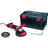
| Product type | Cordless random orbital polisher |
| Brand | Flex |
| Model | XFE 15 150 18.0-EC |
| Rated voltage | 18 V |
| Battery type | Lithium-ion Flex AP 18.0 (2.5/5.0 Ah) |
| Pad diameter | 150 mm (hook-and-loop) |
| Stroke | 15 mm |
| No-load speed | 4600 - 7600 rpm |
| Max. polishing tool diameter | 160 mm |
| Weight (without battery) | 2.15 kg |
| Battery weight (2.5 Ah / 5.0 Ah) | 0.42 kg / 0.72 kg |
| Average runtime (2.5 Ah / 5.0 Ah) | 20 min / 40 min |
| Sound pressure level LpA | 79.9 dB(A) |
| Sound power level LWA | 90.9 dB(A) |
| Total vibration (ah) | 7.2 m/s² |
| Speed presetting dial | Yes |
| Switch with lock-off | Yes |
| Dust filter | Yes, removable |
| Intended use | Polishing of lacquered surfaces, furniture, metals |
| Maintenance | Regular cleaning of ventilation slots and filter |
| Wear parts | Replaceable hook-and-loop backing pad |
Frequently Asked Questions - XFE 15 150 18.0-EC Flex
User questions about XFE 15 150 18.0-EC Flex
0 question about this device. Answer the ones you know or ask your own.
Ask a new question about this device
Download the instructions for your Sander in PDF format for free! Find your manual XFE 15 150 18.0-EC - Flex and take your electronic device back in hand. On this page are published all the documents necessary for the use of your device. XFE 15 150 18.0-EC by Flex.
USER MANUAL XFE 15 150 18.0-EC Flex
natural_image
Illustration of a robotic cleaning tool with a mounted sensor or power shaver (no text or symbols visible)de Originalbetriebsanleitung 3
en Original operating instructions 15
fr Notice d'instructions d'origine 27
it Istruzioni per l'uso originali 39
es Instrucciones de funcionamiento originales ..... 51
pt Instruções de serviço originais 64
nl Originele gebruiksaanwijzing 77
da Originale driftsvejledning 90
no Originale driftsanvisningen 101
sv Originalbruksanvisning 112
fi Alkuperäinen käyttöohjekirja 123
el Auθεντικές οδηγίες χειρισμού 134
tr Orijinal işletme kılavuzu 147
p1 Instrukcja oryginalna 158
hu Eredeti üzemeltetési útmutató 171
cs Originální návod k obsluze 183
sk Originálny návod na obsluhu 194
hr Originalna uputa za rad 205
sl Izvirno navodilo za obratovanje 216
ro Instructiuni de functionare originale 227
bg Оригинално упътване за експлоатация ..... 238
ru Оригинальная инструкция по эксплуатации ..... 251
et Originaalkasutusjuhend 264
It Originali naudojimo instrukcija 275
Iv Lietošanas pamācības oriģināls 286
ar 307
ترجمة لارشادات التشفيل الأصلية
Inhalt
Verwendete Symbole 3
Symbole am Gerät 3
Torx-Schraubenschlüssel T20 *
Gebrauchsanweisung

WARNUNG!
natural_image
Illustration of a mechanical component with a white dome and a black base, showing a downward arrow indicating a process or assembly (no text or symbols present)natural_image
Close-up of a car's side profile with a circular arrow pointing to the nose area, no visible text or symbols.natural_image
Close-up of a car's side profile with a circular vent and directional arrow indicator (no text or symbols)natural_image
Two views of a car's internal components, showing exterior and side views with no visible text or symbols.
Peter Lameli
Technical Head

Klaus Peter Weinper Head of Quality Department (QD)
15.12.2020
Symbols used in this manual ..... 15
Symbols on the power tool 15
For your safety 15
Noise and vibration 17
Technical specifications 18
Overview 19
Instructions for use 20
Maintenance and care 23
Disposal information 25
C€ Declaration of Conformity ..... 25
UK CA Declaration of Conformity ..... 25
Exemption from liability 26
Symbols used in this manual

WARNING!
Denotes impending danger. Non-observance of this warning may result in death or extremely severe injuries.

CAUTION!
Denotes a possibly dangerous situation. Non-observance of this warning may result in slight injury or damage to property.

NOTE
Denotes application tips and important information.
Symbols on the power tool

Before switching on the power tool, read the operating manual!

Wear goggles!
Disposal information for the old machine (see page 25)!
For your safety

WARNING!
Before using the polisher, please read and follow:
– these operating instructions,
- the "General safety instructions" on the handling of power tools in the enclosed booklet (leaflet-no.: 315.915),
– the currently valid site rules and the regulations for the prevention of accidents.
This polisher is state-of-the-art and has been constructed in accordance with the acknowledged safety regulations.
Nevertheless, when in use, the power tool may be a danger to life and limb of the user or a third party, or the power tool or other property may be damaged. The polisher may be used only
- as intended,
– in perfect working order.
Faults which impair safety must be repaired immediately.
Intended use
This hand-operated orbital polisher is designed
– is designed for industrial applications,
– for all types of polishing work, e.g. paint-work on vehicles, furniture and metal surfaces, etc. with polishing sponge,
– for use with polishing tools which are permitted to run at a speed of at least 500 r.p.m..
Safety instructions for polishing

WARNING!
Read all safety warnings, instructions, illustrations and specifications provided with this power tool. Failure to follow all instructions listed below may result in electric shock, fire and/or serious injury. Save all warnings and instructions for future reference.
■ This power tool is intended to function as a polisher. Read all safety warnings, instructions, illustrations and specifications provided with this power tool.
Failure to follow all instructions listed below may result in electric shock, fire and/or serious injury.
■ Operations such as grinding, sanding, wire brushing, or cutting-off are not recommended to be performed with this power tool.
Operations for which the power tool was not designed may create a hazard and cause personal injury.
■ Do not use accessories which are not specifically designed and recommended by the tool manufacturer. Just because the accessory can be attached to your power tool, it does not assure safe operation.
■ The rated speed of the accessory must be at least equal to the maximum speed marked on the power tool. Accessories running faster than their rated speed can break and fly apart.
■ The outside diameter and the thickness of your accessory must be within the capacity rating of your power tool. Incorrectly sized accessories cannot be adequately guarded or controlled.
- Threaded mounting of accessories must match the grinder spindle thread. For accessories mounted by flanges, the arbour hole of the accessory must fit the locating diameter of the flange. Accessories that do not match the mounting hardware of the power tool will run out of balance, vibrate excessively and may cause loss of control.
- Do not use a damaged accessory. Before each use inspect the accessory such as abrasive wheels for chips and cracks, backing pad for cracks, tear or excess wear, wire brush for loose or cracked wires. If power tool or accessory is dropped, inspect for damage or install an undamaged accessory. After inspecting and installing an accessory, position yourself and bystanders away from the plane of the rotating accessory and run the power tool at maximum no-load speed for one minute. Damaged accessories will normally break apart during this test time.
■ Wear personal protective equipment. Depending on application, use face shield, safety goggles or safety glasses. As appropriate, wear dust mask, hearing protectors, gloves and workshop apron capable of stopping small abrasive or workpiece fragments. The eye protection must be capable of stopping flying debris generated by various operations. The dust mask or respirator must be capable of filtrating particles generated by your operation. Prolonged exposure to high intensity noise may cause hearing loss.
- Keep bystanders a safe distance away from work area. Anyone entering the work area must wear personal protective equipment. Fragments of workpiece or of a broken accessory may fly away and cause injury beyond immediate area of operation.
- Hold the power tool by the insulated gripping surfaces when performing an operation where the tool attachment may contact hidden power leads. Cutting accessory contacting a “live” wire may make exposed metal parts of the power tool “live” and could give the operator an electric shock.
■ Never lay the power tool down until the accessory has come to a complete stop. The spinning accessory may grab the surface and pull the power tool out of your control.
■ Do not run the power tool while carrying it at your side. Accidental contact with the spinning accessory could snag your clothing, pulling the accessory into your body.
- Regularly clean the power tool's air vents. The motor's fan will draw the dust inside the housing and excessive accumulation of powdered metal may cause electrical hazards.
■ Do not operate the power tool near flammable materials. Sparks could ignite these materials.
■ Do not use accessories that require liquid coolants. Using water or other liquid coolants may result in electrocution or shock.
Kickback and Related Warnings
Kickback is a sudden reaction to a pinched or snagged rotating wheel, backing pad, brush or any other accessory. Pinching or snagging causes rapid stalling of the rotating accessory which in turn causes the uncontrolled power tool to be forced in the direction opposite of the accessory's rotation at the point of the binding. For example, if an abrasive wheel is snagged or pinched by the workpiece, the edge of the wheel that is entering into the pinch point can dig into the surface of the material causing the wheel to climb out or kick out. The wheel may either jump toward or away from the operator, depending on direction of the wheel's movement at the point of pinching. Abrasive wheels may also break under these conditions. Kickback is the result of power tool misuse and/or incorrect operating procedures or conditions and can be avoided by taking proper precautions as given below.
- Maintain a firm grip on the power tool and position your body and arm to allow you to resist kickback forces. Always use auxiliary handle, if provided, for maximum control over kickback or torque reaction during start-up. The operator can control torque reactions or kickback forces, if proper precautions are taken.
■ Never place your hand near the rotating accessory. Accessory may kickback over your hand. - Do not position your body in the area where power tool will move if kickback occurs. Kickback will propel the tool in direction opposite to the wheel's movement at the point of snagging.
■ Use special care when working corners, sharp edges etc. Avoid bouncing and snagging the accessory. Corners, sharp edges or bouncing have a tendency to snag the rotating accessory and cause loss of control or kickback.
Do not attach a saw chain woodcarving blade or toothed saw blade. Such blades create frequent kickback and loss of control.
Safety Warnings Specific for Polishing Operations
■ Do not allow any loose portion of the polishing bonnet or its attachment strings to spin freely. Tuck away or trim any loose attachment strings.
Loose and spinning attachment strings can entangle your fingers or snag on the workpiece.
Noise and vibration

NOTE
Values for the A-weighted sound pressure level and for the total vibration values can be found in the “Technical specifications” table.
The noise and vibration values have been determined in accordance with EN 62841.

CAUTION!
The indicated measurements refer to new power tools. Daily use causes the noise and vibration values to change.

NOTE
The emission values for vibration and noise provided in these instructions have been measured in accordance with standardised test procedures compliant with EN 62841 and can be used for comparing power tools with each other. They are also suitable for a preliminary estimation of the exposure. The specified levels represent the main applications of the power tools. The noise and emission levels may deviate, however, if the power tool is used for other applications with different accessories or inadequate maintenance. This can significantly increase exposure over the total working period. To make an accurate estimation of the exposure, it is also necessary to take into account the times when the tool is switched off or running but not actually in use. This can significantly decrease exposure over the total working period. Identify additional safety measures to protect the operator from the effects of vibration such as: maintenance of tool and accessories, keep hands warm, standard operating procedures.

CAUTION!
Wear ear protection at a sound pressure above 85 dB(A).
Technical specifications
| XFE 15 125 18.0-ECXFE 15 150 18.0-EC | XCE 8 125 18.0-EC | ||
| Machine type Orbital polisher | |||
| Nominal voltage V 18 | |||
| Battery | AP 18.0/2.5AP 18.0/5.0 | ||
| Tool holder Velcro ∅ 125/150 Velcro | ∅ 125 | ||
| Tool ∅ max. mm 160 | |||
| Orbit mm 15 8 | |||
| No load speed r.p.m. 4,600-7,600 280-430 | |||
| Weight according to “EPTA Procedure 01/2003” (without battery) | kg 2.1 | 2.15 | |
| Weight of battery- AP 18.0/2.5- AP 18.0/5.0 | kg kg | 0.420.72 | |
| Average battery life (depending on speed, tool diameter, load ...) - AP 18.0/2.5- AP 18.0/5.0 | min min | 2040 | |
| A-weighted sound pressure level according to EN 62841 (see “Noise and vibration”): | |||
| Sound pressure level L_pA | dB(A) | 73.2 | 79.9 |
| Sound power level L_WA | dB(A) | 84.2 | 90.9 |
| Uncertainty K | db | 2.5 | |
| Total vibration value according to EN 62841 (see “Noise and vibration”): | |||
| Emission value a_h | m/s2 | 7.2 | 4.9 |
| Uncertainty K | m/s2 | 0.5 | 1.5 |
Overview
Different electric power tools are described in these instructions. The illustrated electric power tool may differ in detail from the one which you purchased.
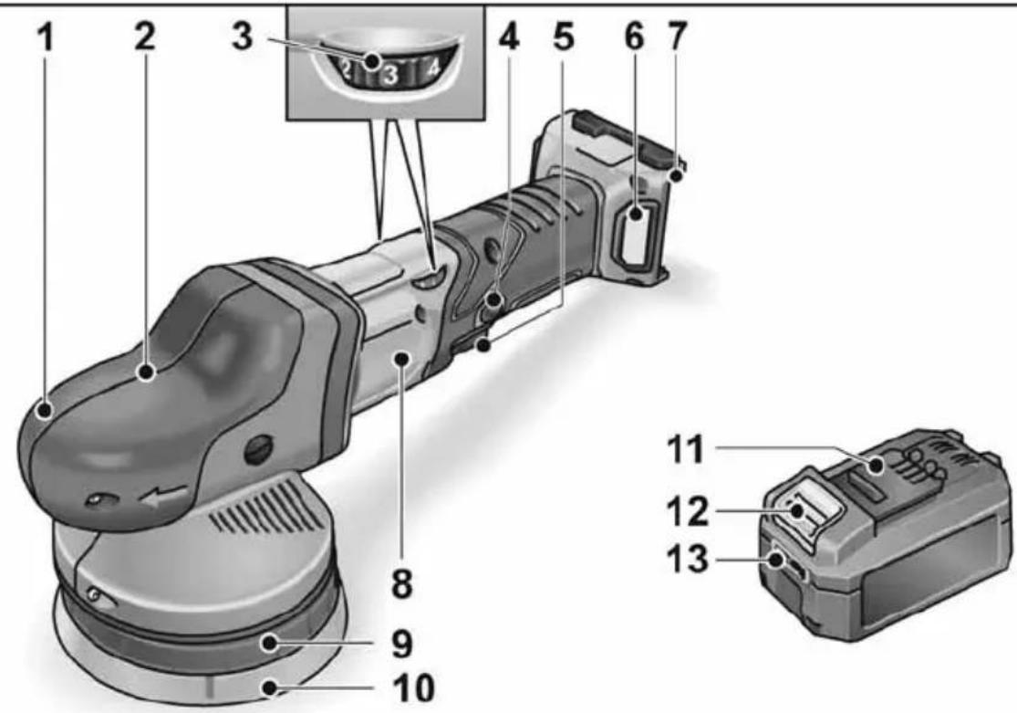
1 Grip hood
With air outlet and direction-of-rotation arrow.
2 Gear head *
3 Dial for preselecting the speed
4 Locking button
Locks the switch (5) during continuous operation.
5 S w i t c h
Switches the power tool on and off and also accelerates it up to the preselected speed.
6 Filter cover
7 Slot for battery
8 Rating plate
9 Disc support
10 Velcro pad
11 Flex Li-ion battery
12 Release button for battery
13 State of charge indicator
Torx wrench T20 *
Instructions for use

WARNING!
Remove the battery before carrying out any work on the power tool.
Before switching on the polisher
Unpack the polisher and check that there are no missing or damaged parts.

NOTE
The batteries are not fully charged on delivery. Prior to initial operation, charge the batteries fully. Refer to the charger operating manual.
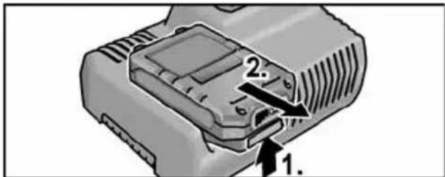
Inserting/replacing the battery
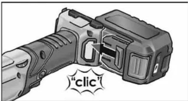
■ Press the charged battery into the power tool until it clicks into place.
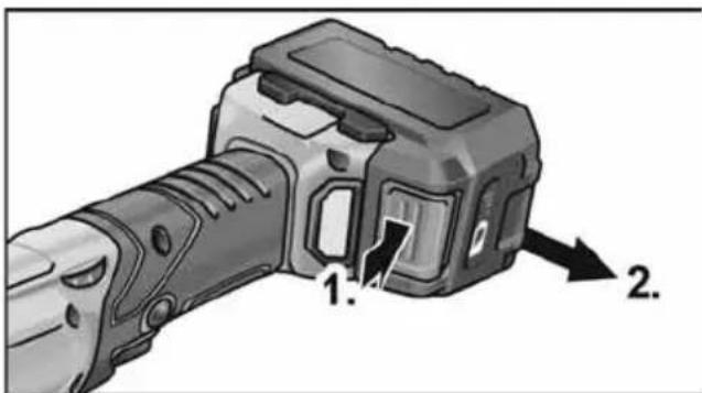
■ To remove, press the release button (1.) and pull out the battery (2.).

CAUTION!
When the device is not in use, protect the battery contacts. Loose metal parts may short-circuit the contacts; explosion and fire hazard!
Battery state of charge
■ Press the button to check the state of charge at the state of charge indicator LEDs.
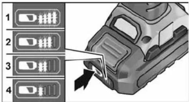
he indicator goes out after 5 seconds. If one of the LEDs flashes, the battery must be recharged. If none of the LEDs light up after the button is pressed, the battery is faulty and must be replaced.
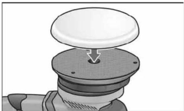
Attaching/changing the tool
■ Remove the battery.
natural_image
Illustration of a mechanical component with a white dome and a downward arrow, no text or symbols present■ Firmly press polishing tool, centred on the eye, onto the Velcro pad. Use undamaged polishing tools only.
■ Insert the battery.
■ Switch on the polisher (without engaging it) and run the polisher for approx. 30 seconds. Check for imbalances and vibrations.
■ Switch off the polisher.
Attaching the tools

CAUTION!
Attach the tools in the centre of the tool holder. Imbalances may damage the power tool. The work result may be impaired.
i NOTE
Use original FLEX accessories on this model. Not using original FLEX accessories may lead to a poor polishing result, increased vibrations and also greater wear or even damage to the power tool.
Information concerning foam wear
i NOTE
In general, foam wear is much higher in connection with free-wheeling eccentric polishing that with rotational polishing or force-driven eccentric polishing.
Due to the drive, this wear does not take place on the outside of the foam but at the foam core instead. The harder/longer the cell structure is subjected to strain and damaged as a result, the faster the build-up of heat. Subsequent damage is inevitable. Wear of this kind cannot be seen on the foam externally. The only reliable action is replacement and disposal in good time to prevent thermal damage to the power tool.
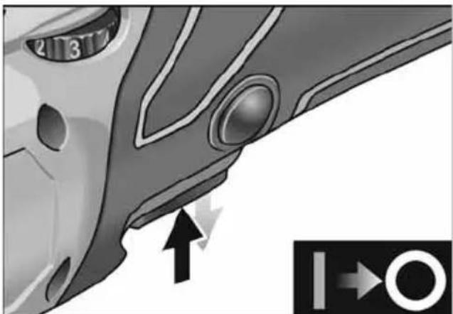
Switch on and off
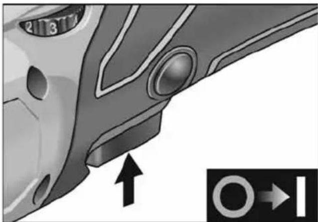
Brief operation without engaged switch rocker
natural_image
Close-up of a car's side profile with circular components and directional arrows (no text or symbols)■ Press and hold down the switch.
■ To switch off, release the switch.
Continuous operation with engaged switch rocker
Switching off/removing the rechargeable battery
- Switch off the electric power tool.
- Switch on the electric power tool again.
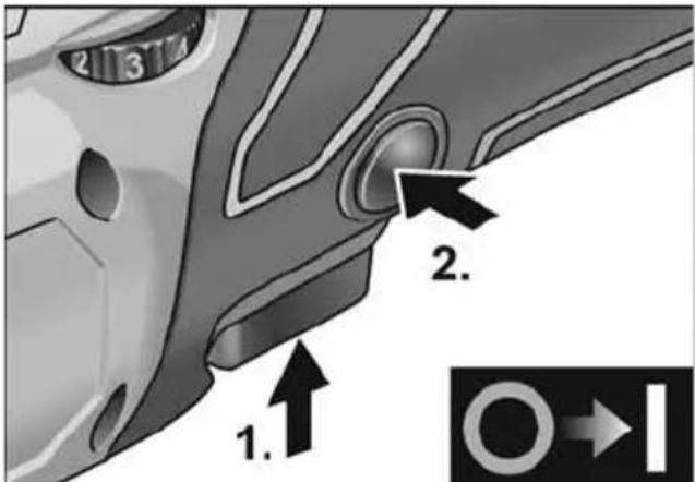
■ Press and hold down the switch (1.).
■ To lock into position, hold down the locking button (2.) and release the switch.
natural_image
Close-up of a car's side profile with a circular vent and directional arrow indicator (no text or symbols)■ To switch off, briefly press and release the switch.
Preselecting the speed
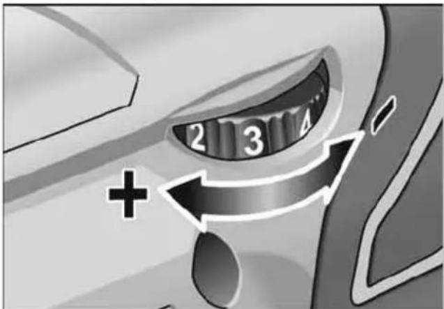
■ To set the operating speed, move the dial to the required value.
■ Gently press the switch to accelerate the power tool up to the preselected speed.
i NOTE
In the event of overload or overheating in non-stop operation, the power tool will switch off.
To continue working, switch the power tool off and back on again.
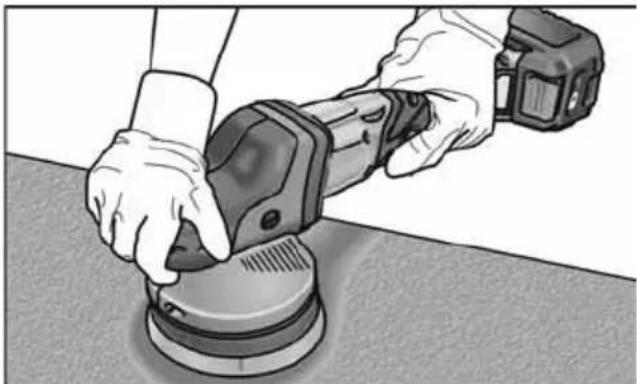
Work instructions
CAUTION!
When the polisher is switched off, the polishing tool continues running briefly.
i NOTE
Following a tool change (e.g. wool pad instead of polishing sponge), the difference in weight may increase the vibrations. Change the operating speed with the adjusting wheel until the vibrations have been reduced.
- Switch on the machine before placing it on the surface which is to be polished and run the polisher up to the set speed.
natural_image
Person using a power tool on a workbench, no visible text or symbols- Move the polishing tool without pressure and make circular, overlapping movements on the surface to be polished in order to achieve good polishing results and to prolong the service life of the tool.
- If using a polishing paste, use the respective tool for each paste.
For further information on the manufacturer's products go to www.flex-tools.com.
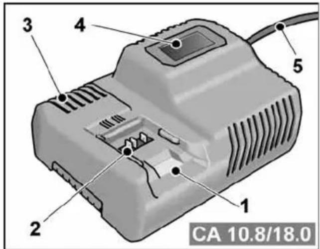
Charger
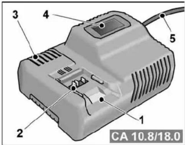
1 Insertion slot for battery
2 Contacts
3 Ventilation slots
4 Operating state display
5 Power cord with mains plug
The CA 10.8/18.0 charger is designed to charge FLEX batteries of the following types
- AP 10.8 (2.5 Ah),
- AP 18.0 (2.5 Ah),
- AP 10.8 (5.0 Ah),
- AP 18.0 (5.0 Ah).
Tips for a long battery service life
CAUTION!
- Never charge batteries at temperatures below 0 °C or above 55 °C.
- Do not charge batteries in environments with high air humidity or ambient temperature
- Do not cover batteries and the charger during the charging process.
– Pull out the charger mains plug at the end of the charging process.
Battery and charger heat up during the charging process. This is perfectly normal! Lithium-ion batteries do not exhibit the established “memory effect”. Nevertheless, a battery should be completely discharged before charging and the charging process should always be fully completed.
If batteries are not used for an extended period of time, store them partially charged in a cool place.
Charging process

CAUTION!
Insert only original batteries in the supplied charger.
■ Insert the charger mains plug. The display backlighting lights up green for 2 seconds and then goes out again. OK is displayed.
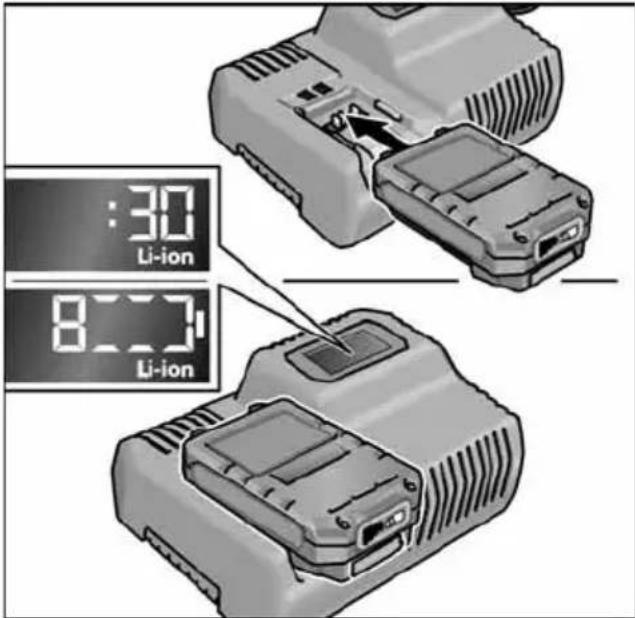
■ Insert the battery fully into the charger until it clicks into place.
- The time remaining in the charging process (until the battery is fully charged) and a graphic representation of the state of charge are shown alternately in the display.
- The display backlighting lights up orange when the battery is charged less than 80%.
- When the battery charge reaches 80% the display lights up green and OK is indicated.
■ The battery is fully charged when the display appears.

The green backlighting goes out after a short time.
■ Remove the battery from the charger.
■ Pull out the mains plug.

NOTE
If the display flashes after the battery is inserted in the charger, there is a fault in the battery or in the charger.

Display flashes slowly. Backlighting orange.
The battery is too hot or too cold. The charging process starts when the battery reaches the charging temperature (0°C...55°C).

Display flashes rapidly. Backlighting red.
Remove the battery from the charger and insert again. If the same display persists, the battery is faulty. Replace the battery or have it checked at an authorised repair shop.
If this error message is displayed again with a different battery, this indicates that there is a fault in the charger. Have the charger checked at an authorised repair shop.
Maintenance and care

WARNING!
Remove the battery before carrying out any work on the power tool.
Cleaning
■ Clean the power tool and grille in front of the vent slots regularly. Frequency of cleaning is dependent on the material and duration of use.
■ Regularly blow out the housing interior and motor with dry compressed air.
■ Regularly clean the filter cover.
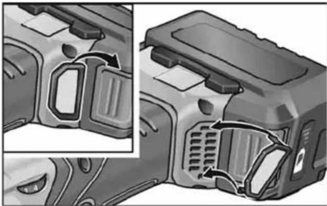
natural_image
Technical illustration of a vehicle's internal components with directional arrows indicating flow or movement (no text or symbols present)Remove filter cover and blow it out with dry compressed air.
Gears
i NOTE
Do not loosen the screws on the gear head during the warranty period.
Non-compliance will deem the guarantee obligations of the manufacturer null and void.
Replacement of wear parts
Change Velcro pad
■ Remove the battery.
■ Remove the polishing tool.
■ Place machine on its back.
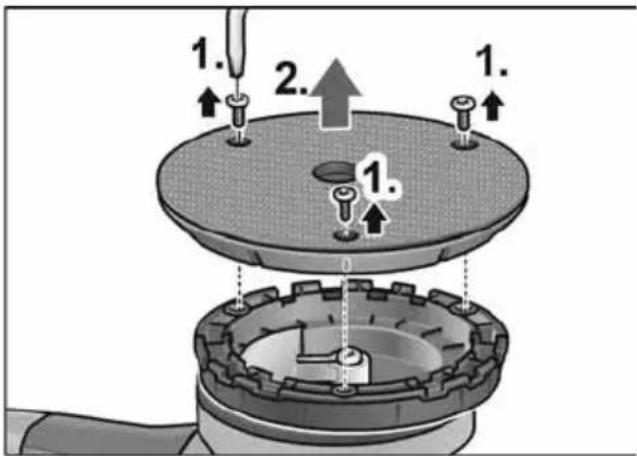
■ Release and remove screws with Torx wrench (1.).
■ Remove worn Velcro pad (2.).
■ Remove contaminants from interior.
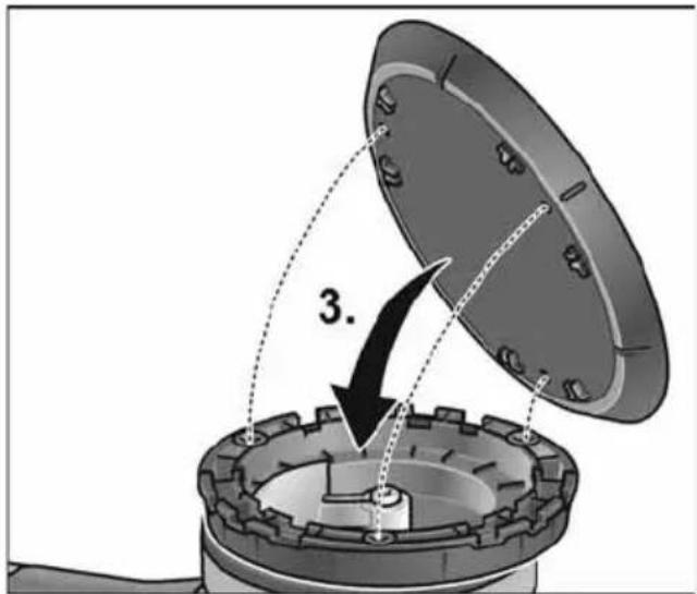
■ Align securing holes and fit new Velcro pad (3.).
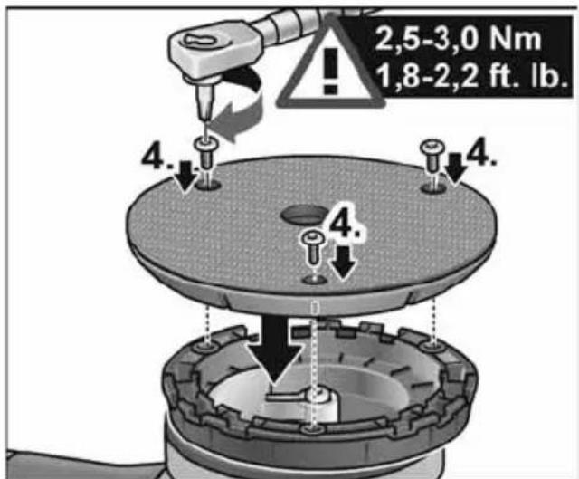
■ Insert screws and tighten with Torx wrench (4.). (Tightening torque 2.5-3.0 Nm (1.8-2.2 ft. lb.))
- Carry out test run. Check for imbalances and vibrations.
CAUTION!
An incorrect torque setting can damage the tool and the surfaces being worked on.
Repairs
Repairs may be carried out by an authorised customer service centre only.
Spare parts and accessories

NOTE
Only the tools released by FLEX may be used.
For other accessories, in particular tools and polishing aids, see the manufacturer's catalogues.
Exploded drawings and spare-part lists can be found on our homepage:
www.flex-tools.com
Disposal information

WARNING!
Render redundant power tools unusable:
- mains operated power tool by removing the power cord,
- battery operated power tool by removing the battery.

EU countries only
Do not throw electric power tools into the household waste!
In accordance with the European Directive 2012/19/EU on Waste Electrical and
Electronic Equipment and transposition into national law used electric power tools must be collected separately and recycled in an environmentally friendly manner.

Raw material recovery instead of waste disposal.
Device, accessories and packaging should be recycled in an environmentally friendly manner. Plastic parts are identified for recycling according to material type.

WARNING!
Do not throw batteries into the household waste, fire or water. Do not open used batteries.
EU countries only:
In accordance with Directive 2006/66/EC defective or used batteries must be recycled

NOTE
Please ask your dealer about disposal options!
C ∈ Declaration of Conformity
We declare under our sole responsibility that the product described under “Technical specifications” conforms to the following standards or normative documents:
EN 62841 in accordance with the regulations of the directives 2014/30/EU, 2006/42/EC, and 2011/65/EU.
Responsible for technical documents: FLEX-Elektrowerkzeuge GmbH, R & D Bahnhofstrasse 15, D-71711 Steinheim/Murr

Peter Lameli
Technical Head

Klaus Peter Weinper Head of Quality Department (QD)
15.12.2020
Declaration of Conformity
We as the manufacturer: FLEX Elektrowerkzeuge GmbH,
Business address: Bahnhofstr. 15, 71711 Steinheim, Germany
declare under our sole responsibility, that the product(s) described under „Technical specifications“ fulfills all the relevant provisions of The Supply of Machinery (Safety) Regulations S.I. 2008/1597 and also fulfills all the relevant provisions of the following UK Regulations:
Electromagnetic Compatibility Regulations S.I. 2016/1091, The Restriction of the Use of Certain Hazardous Substances in Electrical and Electronic Equipment Regulations S.I. 2012/3032 and are manufactured in accordance with the following designated Standards: BS EN 62841-1:2015, BS EN 62841-2-4:2014, BS EN 55014-1:2017, BS EN 55014-2:2015
Place of declaration: Steinheim, Germany. Responsible person: Peter Lameli, Technical Director – FLEX-Elektrowerk- zeuge GmbH
Contact details for Great Britain:
FLEX Power Tools Limited,
Unit 8 Anglo Office Park, Lincoln Road,
HP 12, 3RH Buckinghamshire,
United Kingdom

Peter Lameli Technical Head
Klaus Peter Weinper Head of Quality Department (QD)
19.05.2021
Exemption from liability
The manufacturer and his representative are not liable for any damage and lost profit due to interruption in business caused by the product or by an unusable product.
The manufacturer and his representative are not liable for any damage which was caused by improper use of the power tool or by use of the power tool with products from other manufacturers.
Table des matières
natural_image
Illustration of a mechanical component with a white dome and a black base, showing a downward arrow indicating force or direction (no text or symbols)natural_image
Close-up of a car's side profile with a circular component and directional arrow, no visible text or symbolsnatural_image
Close-up of a car's side profile with a circular vent and directional arrow indicator (no text or symbols)natural_image
Person using a power tool on a workbench, no visible text or symbols- AP 10.8 (2,5 Ah),
- AP 18.0 (2,5 Ah),
- AP 10.8 (5,0 Ah),
- AP 18.0 (5,0 Ah).
natural_image
Two views of a car's front bumper showing internal components and airflow direction (no text or symbols)natural_image
Illustration of a mechanical component with a white dome and a black base, showing a downward arrow indicating force or direction (no text or symbols)Peter Lameli
Technical Head
Klaus Peter Weinper
Head of Quality
Department (QD)
15.12.2020
natural_image
Mechanical component diagram showing a knob pressing into a housing (no text or symbols)natural_image
Close-up of a car's side profile with circular components and directional arrows (no text or symbols)natural_image
Close-up of a car's side panel showing a circular vent and a directional arrow (no text or symbols)natural_image
Person using a power tool on a tiled floor, no visible text or symbols- AP 10.8 (2,5 Ah),
- AP 18.0 (2,5 Ah),
- AP 10.8 (5,0 Ah),
- AP 18.0 (5,0 Ah).
natural_image
Two views of a car air vent assembly showing internal components and airflow direction (no text or symbols)
Peter Lameli
Technical Head

Klaus Peter Weinper Head of Quality Department (QD)
15.12.2020
natural_image
Illustration of a mechanical component with a white top and a black base, showing a downward arrow indicating a process or assembly (no text or symbols present)natural_image
Close-up of a car's side profile with a circular component and directional arrow, no visible text or symbolsnatural_image
Close-up of a car's side profile with a circular vent and directional arrow indicator (no text or symbols)natural_image
Person using a power tool on a workbench, no visible text or symbols- AP 10.8 (2,5 Ah),
- AP 18.0 (2,5 Ah),
- AP 10.8 (5,0 Ah),
- AP 18.0 (5,0 Ah).
natural_image
Two views of a car engine compartment showing internal components and airflow direction (no text or symbols)natural_image
Illustration of a mechanical component with a white dome and a black base, showing a downward arrow indicating a process or assembly (no text or symbols present)natural_image
Close-up of a car's side panel with a circular button and directional arrow, no visible text or symbolsnatural_image
Close-up of a car's side profile with highlighted eye area and directional arrow (no text or symbols)natural_image
Person using a power tool on a workbench, no visible text or symbols- AP 10.8 (2,5 Ah),
- AP 18.0 (2,5 Ah),
- AP 10.8 (5,0 Ah),
- AP 18.0 (5,0 Ah).
natural_image
Two views of a car engine compartment showing internal components and airflow direction (no text or symbols)Peter Lameli Technical Head
Klaus Peter Weinper Head of Quality Department (QD)
natural_image
Illustration of a mechanical component with a white top and gray base, showing a downward arrow indicating a process or assembly (no text or symbols present)natural_image
Close-up of a car's side profile with a circular lens and directional arrow indicator (no text or symbols)natural_image
Close-up of a car's side profile with a circular vent and directional arrow indicator (no text or symbols)natural_image
Person using a power tool on a workbench (no text or symbols visible)- AP 10.8 (2,5 Ah),
- AP 18.0 (2,5 Ah),
- AP 10.8 (5,0 Ah),
- AP 18.0 (5,0 Ah).
natural_image
Two views of a car engine compartment showing internal components and airflow direction (no text or symbols)Peter Lameli Technical Head
Klaus Peter Weinper Head of Quality Department (QD)
15-12-2020
natural_image
Illustration of a mechanical component with a white dome and a black base, showing a downward arrow indicating a process or assembly (no text or symbols present)natural_image
Close-up of a car's side profile with a circular button and directional arrow, no visible text or symbolsnatural_image
Close-up of a car's side panel showing a circular component with an arrow pointing to it, alongside a directional indicator (no text or symbols on the main subject)natural_image
Person using a power tool on a workbench, no visible text or symbolsnatural_image
Two views of a car air vent assembly showing internal components and airflow direction (no text or symbols)Peter Lameli Technical Head

Klaus Peter Weinper Head of Quality Department (QD)
15-12-2020
natural_image
Illustration of a mechanical component with a white dome and central bolt, showing a downward arrow (no text or symbols)natural_image
Close-up of a car's side profile with circular components and directional arrows (no text or symbols)natural_image
Close-up of a car's side profile with highlighted eye area and directional arrow (no text or symbols)natural_image
Person using a power tool on a workbench, no visible text or symbolsnatural_image
Two views of a mechanical device showing internal components and airflow direction (no text or symbols)
Peter Lameli
Technical Head

Klaus Peter Weinper Head of Quality Department (QD)
15.12.2020
natural_image
Mechanical component diagram showing a top view of a flanged base with a central hole and an arrow indicating force or movement (no text or symbols present)natural_image
Close-up of a car's side profile with a circular lens and directional arrow indicator (no text or symbols)natural_image
Close-up of a car's side profile with a circular vent and directional arrow indicator (no text or symbols)- AP 10.8 (2,5 Ah),
- AP 18.0 (2,5 Ah),
- AP 10.8 (5,0 Ah),
- AP 18.0 (5,0 Ah).
natural_image
Mechanical component diagram showing a knob pressing into a housing (no text or symbols)natural_image
Close-up of a car's side profile with a circular component and directional arrow, no visible text or symbolsnatural_image
Close-up of a car's side panel with a circular vent and directional arrow indicator (no text or symbols)natural_image
Person using a power tool on a workbench, no visible text or symbols1 Akkukuilu
2 Liittimet
3 Tuuletusraot
natural_image
Two views of a car air vent assembly showing internal components and airflow direction (no text or symbols)
Peter Lameli
Technical Head

Klaus Peter Weinper Head of Quality Department (QD)
15.12.2020
natural_image
Illustration of a mechanical component with a white dome and a central hole, no text or symbols presentnatural_image
Close-up of a car's side profile with circular components and directional arrows (no text or symbols)natural_image
Close-up of a car's side profile with a circular button and directional arrow, no visible text or symbols| 1 | Y | o | o | ||||
| 2 | E |
3 Σχισμές αερισμού
- AP 10.8 (2,5 Ah),
- AP 18.0 (2,5 Ah),
- AP 10.8 (5,0 Ah),
- AP 18.0 (5,0 Ah).
natural_image
Two views of a car air vent assembly showing internal components and airflow direction (no text or symbols)natural_image
Mechanical component diagram showing a knob pressing into a housing (no text or symbols)natural_image
Close-up of a car's side profile with circular components and directional arrows (no text or symbols)natural_image
Close-up of a car's side panel showing a circular button and directional arrow (no text or symbols)natural_image
Person using a power tool on a circular workpiece (no text or symbols visible)natural_image
Two views of a mechanical device showing internal components and airflow direction (no text or symbols)
Peter Lameli
Technical Head

Klaus Peter Weinper Head of Quality Department (QD)
15.12.2020
natural_image
Mechanical component diagram showing a knob pressing into a housing (no text or symbols)natural_image
Close-up of a car's side profile with circular components and directional arrows (no text or symbols)natural_image
Close-up of a car's side profile with a circular vent and directional arrow indicator (no text or symbols)natural_image
Person using a power tool on a workbench (no text or symbols visible)- AP 10.8 (2,5 Ah),
- AP 18.0 (2,5 Ah),
- AP 10.8 (5,0 Ah),
- AP 18.0 (5,0 Ah).
natural_image
Two views of a vehicle's internal components, showing structural parts with arrows indicating movement or flow (no text or symbols present)Peter Lameli Technical Head
Klaus Peter Weinper Head of Quality Department (QD)
15.12.2020
natural_image
Illustration of a mechanical component with a white dome and a black base, showing a downward arrow indicating a process or assembly (no text or symbols present)natural_image
Close-up of a car's side profile with a circular component and directional arrow, no visible text or symbolsnatural_image
Close-up of a car's side profile with a circular vent and directional arrow indicator (no text or symbols)natural_image
Person using a power tool on a workbench, no visible text or symbols1 Az akku rekesze
2 Érintkezők
3 Szellőzőnyílások
natural_image
Two views of a car's front panel showing internal components and airflow direction (no text or symbols)
Peter Lameli
Technical Head

Klaus Peter Weinper Head of Quality Department (QD)
-
- 15
natural_image
Mechanical component diagram showing a knob pressing into a housing (no text or symbols)natural_image
Close-up of a car's side profile with a circular component and directional arrow, no visible text or symbolsnatural_image
Close-up of a car's side profile with a circular vent and directional arrow indicator (no text or symbols)natural_image
Person using a power tool on a workbench (no text or symbols visible)- AP 10.8 (2,5 Ah),
- AP 18.0 (2,5 Ah),
- AP 10.8 (5,0 Ah),
- AP 18.0 (5,0 Ah).
natural_image
Two views of a firearm component showing internal structure and airflow direction (no text or symbols)Peter Lameli Technical Head

Klaus Peter Weinper Head of Quality Department (QD)
15.12.2020
natural_image
Illustration of a mechanical component with a white top and gray base, showing a downward arrow indicating a process or assembly (no text or symbols present)■ Pritlacte pevne leštiaci nástroj, vystredený podla oka, na tanier so suchým zipsom. Používajte len nepoškodené leštiace nástroje.
■ Vložte akumulátor.
■ Zapnite ručnú leštičku (bez zaskočenia) a nechajte ju cca 30 sekúnd v chode. Skontrolujte nevyváženost' a vibrácie.
■ Vypnite ručnú leštičku.
natural_image
Close-up of a car's side profile with a circular arrow pointing to the front wheel (no text or symbols)natural_image
Close-up of a car's side profile with a circular button and directional arrow, no visible text or symbolsnatural_image
Person using a power tool on a workbench (no text or symbols visible)natural_image
Close-up of a mechanical component with a highlighted part and a magnified view of a small circular detail (no text or symbols visible)
natural_image
Exterior view of a mechanical device with internal components (no visible text or symbols)natural_image
Illustration of a mechanical component with a white dome and a black base, showing a downward arrow indicating a process or assembly (no text or symbols present)■ Sredstvo za poliranje centrirano odoka utisnuti na disk za brusni papir. Upotrebljavati neoštećeni alat za poliranje.
■ Umetnite akumulator.
■ Uključite uređaj za poliranje (bez da ga učvrstite do klika) i pustite da radi cca 30 sekundi. Provjeriti u odnosu na neuravnoteženost i vibracije.
■ Isključite uređaj za poliranje.
natural_image
Close-up of a car's side panel with circular components and directional arrows indicating movement (no text or symbols)natural_image
Close-up of a car's side panel showing a circular component and directional arrow (no text or symbols)natural_image
Person using a power tool on a workbench, no visible text or symbols1 Otvor za umetanje akumulatora
2 Kontakti
3 Prorezi za ventilaciju
4 Zaslon za prikaz radnog stanja
5 Mrežni kabel s mrežnim utikačem
Punjač CA 10.8/18.0 namijenjen je za punjenje FLEX akumulatora tipa
- AP 10.8 (2,5 Ah),
- AP 18.0 (2,5 Ah),
- AP 10.8 (5,0 Ah),
- AP 18.0 (5,0 Ah).
natural_image
Two views of a vehicle's internal components, showing internal parts with arrows indicating flow or movement (no text or symbols present)Izvadite filtar za prašinu i ispušite suhim komprimiranim zrakom.
Prijenosnik
i NAPUTAK!
Klaus Peter Weinper
Head of Quality
Department (QD)
15.12.2020
Hrup in tresljaji 218
natural_image
Mechanical component diagram showing a knob pressing into a housing (no text or symbols)natural_image
Close-up of a car's side profile with a circular button and directional arrow, no visible text or symbols■ Pritisnite in pridržite stikalo.
■ Za izklop sprostite stikalon.
Trajno delovanje z zaklepom
Izklop/odstranitev akumulatorske baterije
– Izklopite električno orodje.
– Ponovno vklopite električno orodje.

■ Pritisnite in pridržite stikalo (1.).
■ Za zaklep položaja pridržite gumb za zaklep (2.) in sprostite stikalo.

natural_image
Close-up of a car's side profile with a circular vent and directional arrow indicator (no text or symbols)■ Za izklop stikalo na kratko pritisnite in ga nato izpustite.
natural_image
Person using a power tool on a workbench, no visible text or symbols– Polirnik nežno pritisnite na površino za poliranje in ga premikajte s krožnimi gibi, ki se prekrivajo, da zagotovite dober rezultat poliranja in dolgo življenjsko dobo orodja.
– Pri uporabi polirne paste za posamezno pasto uporabite ustrezno orodje.
Dodatne informacije o naših izdelkih so na voljo na www.flex-tools.com.
Polnilnik
1 Reža za vstavljanje akumulatorske baterije
- AP 10.8 (2,5 Ah),
- AP 18.0 (2,5 Ah),
- AP 10.8 (5,0 Ah),
- AP 18.0 (5,0 Ah).
natural_image
Two views of a vehicle's internal components, showing exterior and side views with no visible text or symbols.Snemite filter za prah in ga izpihajte s suhim stisnjenim zrakom.
Gonilo
i OPOMBA

Peter Lameli
Technical Head

Klaus Peter Weinper Head of Quality Department (QD)
15.12.2020
natural_image
Illustration of a mechanical component with a white dome and central hole, showing a downward arrow (no text or symbols)natural_image
Close-up of a car's side profile with a circular lens and directional arrow indicator (no text or symbols)natural_image
Close-up of a car's side panel showing a circular vent and a directional arrow (no text or symbols)natural_image
Person using a power tool on a workbench, no visible text or symbolsnatural_image
Two views of a vehicle's internal components, showing exterior and side views with arrows indicating movement or flow (no text or symbols present)EN 62841 conform prevederilor Directivei 2014/30/UE, 2006/42/CE, 2011/65/UE.
Responsabili pentru documente tehnice: FLEX-Elektrowerkzeuge GmbH, R & D Bahnhofstrasse 15, D-71711 Steinheim/Murr

Peter Lameli
Technical Head

Klaus Peter Weinper Head of Quality Department (QD)
15.12.2020
natural_image
Illustration of a mechanical component with a white top and a black base, showing a downward arrow indicating a process or assembly (no text or symbols present)natural_image
Close-up of a car's side profile with a circular component and directional arrow (no text or symbols)natural_image
Close-up of a car's side panel showing the nose and eye area with an arrow pointing to a circular symbol (no text or labels)natural_image
Person using a power tool on a workbench, no visible text or symbolsnatural_image
Two views of a vehicle's internal components, showing front and side views with no visible text or symbols.
Peter Lameli
Technical Head

Klaus Peter Weinper Head of Quality Department (QD)
15.12.2020
natural_image
Illustration of a mechanical component with a white top and gray base, showing a downward arrow indicating a process or assembly (no text or symbols present)natural_image
Close-up of a car's side profile with a circular component and directional arrow, no visible text or symbolsnatural_image
Close-up of a car's side panel with a circular vent and directional arrow indicator (no text or symbols)natural_image
Person using a power tool on a workbench, no visible text or symbols- AP 10.8 (5,0 A*4),
- AP 18.0 (5,0 A*4).
natural_image
Two views of a car air vent assembly showing internal components and airflow direction (no text or symbols)Klaus Peter Weinper
Head of Quality
Department (QD)
15.12.2020
natural_image
Illustration of a mechanical component with a white top and gray base, showing a downward arrow indicating a process or assembly (no text or symbols present)natural_image
Close-up of a car's side profile with a circular component and directional arrow indicator (no text or symbols)natural_image
Close-up of a car's side profile with a circular vent and directional arrow indicator (no text or symbols)natural_image
Person using a power tool on a workbench (no text or symbols visible)1 Aku pesa
2 K o n t a k t i
- AP 10.8 (2,5 Ah),
- AP 18.0 (2,5 Ah),
- AP 10.8 (5,0 Ah),
- AP 18.0 (5,0 Ah).
natural_image
Two views of a car's internal components, showing exterior and side views with no visible text or symbols.natural_image
Close-up of a mechanical component with a white dome and a black base, showing a downward arrow indicating a process or assembly (no text or symbols present)natural_image
Close-up of a car's side profile with circular components and directional arrows (no text or symbols)natural_image
Close-up of a car's side profile with a circular vent and directional arrow indicator (no text or symbols)natural_image
Person using a power tool on a workbench (no text or symbols visible)- AP 10.8 (2,5 Ah), - AP 18.0 (2,5 Ah), - AP 10.8 (5,0 Ah), - AP 18.0 (5,0 Ah).
natural_image
Two views of a vehicle's internal components, showing internal parts with arrows indicating movement or flow (no text or symbols present)
Peter Lameli
Technical Head

Klaus Peter Weinper Head of Quality Department (QD)
2020-12-15
natural_image
Illustration of a mechanical component with a white top and gray base, showing a downward arrow indicating a process or assembly (no text or symbols present)natural_image
Close-up of a car's side profile with a circular component and directional arrow, no visible text or symbols■ Spiediet slēdzi un turiet to nospiestu.
natural_image
Close-up of a car's side panel showing a circular component with an arrow pointing to it, and a directional indicator (no text or symbols)natural_image
Person using a power tool on a workbench, no visible text or symbols- AP 10.8 (2,5 Ah),
- AP 18.0 (2,5 Ah),
- AP 10.8 (5,0 Ah),
- AP 18.0 (5,0 Ah).
natural_image
Two views of a car's internal components showing airflow or ventilation (no text or symbols visible)Nonemiet puteklu filtru un izpūtiet to ar sausu saspiesto gaisu.
Pārvads
i NORĀDĪJUMS!

Peter Lameli
Technical Head

Klaus Peter Weinper Head of Quality Department (QD)
15.12.2020
Peter Lameli Technical Head

Klaus Peter Weinper Head of Quality Department (QD)
2020/12/15
natural_image
Two views of a car air vent assembly showing internal components and airflow direction (no text or symbols).80% ي Had Shun the Bpatarine Aqll mcn
natural_image
Person using a power tool on a workbench, no visible text or symbolsnatural_image
Close-up of a car's side panel showing the nose and mouth, with an arrow pointing to a circular component (no text or symbols visible)natural_image
Close-up of a car's side profile with circular components and directional arrows (no text or symbols)natural_image
Close-up of a mechanical component with a white dome and a black base, showing a downward arrow indicating a process or assembly (no text or symbols present)غطاء الفلتر 6
11 - ar ⊆ ∪ ∪ ∪ ∪ ∪ ∪ ∪ ∪ ∪ ∪ ∪ ∪ ∪ ∪ ∪ ∪ ∪ ∪ ∪ ∪ ∪ ∪ ∪ ∪ ∪ ∪ ∪ ∪ ∪ ∪ ∪ ∪ ∪ ∪ ∪ ∪ ∪ ∪ ∪ ∪ ∪ ∪ ∪ ∪ ∪ ∪ ∪ ∪ ∪ ∪ ∸ ∪ ∸ ∸ ∸ ∸ ∸ ∸ ∸ ∸ ∸ ∸ ∸ ∸ ∸ ∸ ∸ ∸ ∸ ∸ ∸ ∸ ∸ ∸ ∸ ∸ ∸ ∸ ∸ ∸ ∸ ∸ ∸ ∸ ∸ ∸ ∸ ∸ ∸ ∸
11 - ar ...... إخلاء Meadowsية


- Inhalt
- Gebrauchsanweisung
- WARNUNG!
- Symbols used in this manual
- WARNING!
- CAUTION!
- NOTE
- Symbols on the power tool
- For your safety
- Intended use
- Safety instructions for polishing
- Kickback and Related Warnings
- Safety Warnings Specific for Polishing Operations
- Noise and vibration
- Overview
- Instructions for use
- Before switching on the polisher
- Inserting/replacing the battery
- Battery state of charge
- Attaching/changing the tool
- Attaching the tools
- i NOTE
- Information concerning foam wear
- Switch on and off
- Continuous operation with engaged switch rocker
- Preselecting the speed
- Work instructions
- Tips for a long battery service life
- Charging process
- Maintenance and care
- Cleaning
- Gears
- Replacement of wear parts
- Change Velcro pad
- Repairs
- Spare parts and accessories
- Disposal information
- C ∈ Declaration of Conformity
- Declaration of Conformity
- Exemption from liability
- Table des matières
- Prijenosnik
- i NAPUTAK!
- Trajno delovanje z zaklepom
- Gonilo
- i OPOMBA
- Pārvads
- i NORĀDĪJUMS!
Brand : Flex
Model : XFE 15 150 18.0-EC
Category : Sander