AC3201 E - Camping Eurom - Free user manual and instructions
Find the device manual for free AC3201 E Eurom in PDF.

| Brand | Eurom |
| Model | AC3201 E |
| Product type | Portable air conditioner for caravans and motorhomes |
| Dimensions (indoor unit) | 395 x 360 x 185 mm |
| Dimensions (outdoor unit) | 440 x 380 x 200 mm |
| Total weight | 22.5 kg |
| Supply voltage | 220-240 V~ / 50 Hz |
| Power consumption | 340 - 361 W |
| Cooling capacity | 2500 - 3200 BTU |
| Refrigerant | R290 (90 g) |
| Airflow rate | 100 / 200 m³/h (low/high speed) |
| Operating temperature range | 16 °C to 43 °C (max 42 °C high speed, 38 °C low speed) |
| Protection rating (outdoor unit) | IPX4 |
| Protection rating (indoor unit) | IP20 |
| Protection class | Class I |
| Main functions | Continuous cooling, timer (0.5 / 1 / 2 / 4 / 7.5 h), two speeds, automatic condensate drainage |
| Maintenance and cleaning | Cleaning of the removable filter with clear water, vacuum the openings, exterior cleaning with a damp cloth |
| Safety | Automatic shut-off in case of drainage malfunction, compressor protection (5 min delay), overflow prevention |
| Warranty | 24 months (excluding normal wear and misuse) |
| Package contents | Indoor and outdoor units, brackets, caps, hooks, drainage hose, manual |
Frequently Asked Questions - AC3201 E Eurom
User questions about AC3201 E Eurom
0 question about this device. Answer the ones you know or ask your own.
Ask a new question about this device
Download the instructions for your Camping in PDF format for free! Find your manual AC3201 E - Eurom and take your electronic device back in hand. On this page are published all the documents necessary for the use of your device. AC3201 E by Eurom.
USER MANUAL AC3201 E Eurom
natural_image
Two white electric heating cabinets with ventilation grilles, one displaying a green indicator light and the other showing a logo and label (no visible text or symbols on main body)NL 3
EN 19
DE 33
FR 49
IT 65
SV 81
DA 95
FI 109
NO 124
CS 138
This appliance is suitable for use only in caravans and motorhomes.
Model: Product code:
AC3201 E 382570
Figuur 2.
natural_image
Technical diagram of a device rear panel with labeled parts (1, 2), showing internal structure and mounting hardware (no text or symbols beyond labels)Figuur 4.

Figuur 5.
Installatie

WAARSCHUWING
Figuur 6.
Figuur 7.
Figuur 8.
Figuur 9.
Figuur 10.
Figuur 11.
Werking

WAARSCHUWING
Figuur 12.
Snelheidsinstelling
Figuur 16.
Afdanken

natural_image
Symbol of recycling with a trash bin and recycling symbol (no text or labels)Please read and understand these safety instructions. Incorrect use can cause injury and will void EUROM's warranty.
- Read all the safety instructions carefully before use and keep this instructions for further use.
- This appliance can be used by children aged from 8 years and above and persons with reduced physical, sensory or mental capabilities or lack of experience and knowledge if they have been given supervision or instruction concerning use of the appliance in a safe way and understand the hazards involved. Children shall not play with appliance. Cleaning and user maintenance shall not be made by children without supervision.
- If the supply cord is damaged, it must be replaced by the manufacturer, its service agent or similarly qualified persons in order to avoid a hazard.
- The appliance shall be installed in accordance with national wiring regulations.
- This appliance is only suitable for use in caravans and motorhomes. Never use this appliance in other environments than caravans and motorhomes.
Additional warnings for appliances with R290 refrigerant gas
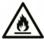
CAUTION
R290 is flammable: risk of fire.
•R290 refrigerant gas complies with European environmental directives. This appliance contains approximately 90 g of R290 refrigerant gas.
- Do not use any means to accelerate the defrosting process or to clean the appliance, other than those recommended by the manufacturer.
- The appliance shall be stored in a room without activated ignition sources (for example: open flames, an activated gas appliance or an activated electric heater).
- Do not pierce or burn.
- Do not perforate any part of the refrigerant circuit and do not set the appliance on fire.
- Be aware that refrigerants do not have a discernible odour – you cannot smell a gas leak!
- The appliance shall be installed, operated and stored in a room with a floor area larger than 4m^2 .
- Always provide some ventilation in the room where the appliance is installed, operated and stored.
- The appliance must be installed, operated and stored in such a way that any mechanical defects are prevented. Be especially careful with the refrigerant hose between the indoor and outdoor unit.
- Persons working on the cooling circuit must be in possession of the correct qualifications that state the person in question is competent to use coolant in accordance with a special evaluation that is recognised by the sector association.
- Repairs must be carried out according to the recommendations of the manufacturer of the device. Maintenance and repairs that require the assistance of other qualified persons must be carried out under supervision of someone who is specialised in the use of flammable coolant.
Considering this is an appliance using R290 refrigerants, a service and operation manual for this appliance is available on request. It is strictly forbidden for end-users to charge refrigerant by themselves.
General safety instructions

WARNING
- Prevent splashing water on or in the device.
- Do not immerse any part of the device in water or other liquids.
- Never insert fingers or other objects into the openings of the device.
- Do not expose the device to strong vibrations or mechanical stress.

CAUTION
Make sure the device remains upright at all times. If the device or part of it has been lying horizontally, wait 2 hours before use.
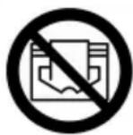
CAUTION
Do not cover the device during usage or usage. To reduce the risk of fire, keep textiles, curtains, tent canvasses and other flammable material at a minimum distance of 50 centimeters from the device.
Safety during operation
WARNING
Do not use the device:
- lying, leaning, hanging crooked or tilted;
- if any parts are dirty or wet;
- if there is a strange noise, smell or smoke;
•near a water source, like a sink, shower or swimming pool;
• in the rain (outdoor unit resistance up to 10 liters per minute);
• in constant direct sunlight exposure; - near or in a dusty and dirty environment, like a construction site;
- near flammable materials, liquids or fumes, like insect repellent sprays, splattering oil, gas cylinders or gas hoses;
•near a heat source or open fire; - with an appliance that automatically switches the device on, such as a timer, dimmer or any other similar device.
If the device, the electric cable or plug shows damage or is malfunctioning, immediately take the appliance out of use and disconnect the power supply.


WARNING
The indoor unit does not have a protection rating against moisture and water. Never use the indoor unit in a damp or wet environment.

CAUTION
This air conditioner produces condensation water. This water is discharged directly through the bottom of the outdoor unit. Make sure the outdoor unit is placed outside and the water can be discharged safely without damaging other objects.
Warranty
EUROM offers a 24-month warranty on this device from the date of purchase. The warranty does not cover wear and tear from normal use. The warranty expires if a defect is the result of unintentional or careless use of the device. The manufacturer, importer and supplier are not liable for incorrect connections.
Introduction
Thank you for choosing this EUROM device. You have purchased a quality device that you will enjoy for many years. Using this device with respect and care will reduce the risk of personal injury or material damage.

CAUTION
It is important to read and understand this instruction manual before assembling, installing and using the device.
This manual describes the correct and safe use of this device. Keep this manual for future reference. The manual is an essential part of the device and must be given to the new owner upon resale or exchange. This manual has been compiled with the utmost care. Nevertheless, we reserve the right to improve and adjust this manual at any time. The images used may differ.
The following symbols and terms are used in this manual to alert the reader to safety issues and important information:

WARNING
Indicates a hazardous situation which, if the safety instructions are not followed, can lead to injuries to the operator or bystanders, light and/or moderate damage to the product or to the environment.

CAUTION
Indicates a hazardous situation which, if the safety instructions are not followed, can lead to light and/or moderate damage to the product or to the environment.
Identification
EUROM®
POWERFUL PRODUCTS SINCE 1974
AC3201 E
Art.nr. 382570
EAN: 8713415382570
| Power | 220-240V / 50Hz |
| Power usage | 340 - 361 Watt |
| Cooling capacity | 2500 BTU - 3200 BTU |
| Refrigerant | R290 (90gr) |
| Discharge pressure | 2,13 MPa |
| Suction pressure | 0,64 MPa |
| Max. allowed pressure | 2,83 MPa |
| Outdoor unit | IPX4 |
Batchno.

EUROM - KOKOSSTRAAT 20 - 8281 JC - GENEMUIDEN - NETHERLANDS
Figure 17.
Specifications
| Type AC3201 E | |
| Product size indoor unit 395 x 360 x 185 mm | |
| Product size outdoor unit 440 x 380 x 200 mm | |
| Weight 22.5 kg | |
| Voltage 220-240V~ / 50Hz | |
| Power consumption 340-361 W | |
| Current consumption 1,5-1,6 A | |
| Cooling capacity 2500 BTU-3200 BTU | |
| Cooling liquid R290 (90 g) | |
| Compressor type Rotating | |
| Airflow 100/200 m | ^3/h |
| Working temperature 16-43 °C | |
| Protection rating outdoor unit IPX4 | |
| Protection rating indoor unit IP20 | |
| Protective class Class I |
Description
This EUROM device is an easy-to-use portable caravan air-conditioner for caravan use only. The device provides continuous cooling and produces condensed water.
Unboxing

WARNING
Plastic bags can be dangerous. To avoid danger of suffocation, keep this bag away from babies and children.
The device is packed in one box. Remove all packaging material and check that the device is not damaged. Do not use the device if it is damaged, but always contact your supplier. Keep the packaging for safe storage and transport.
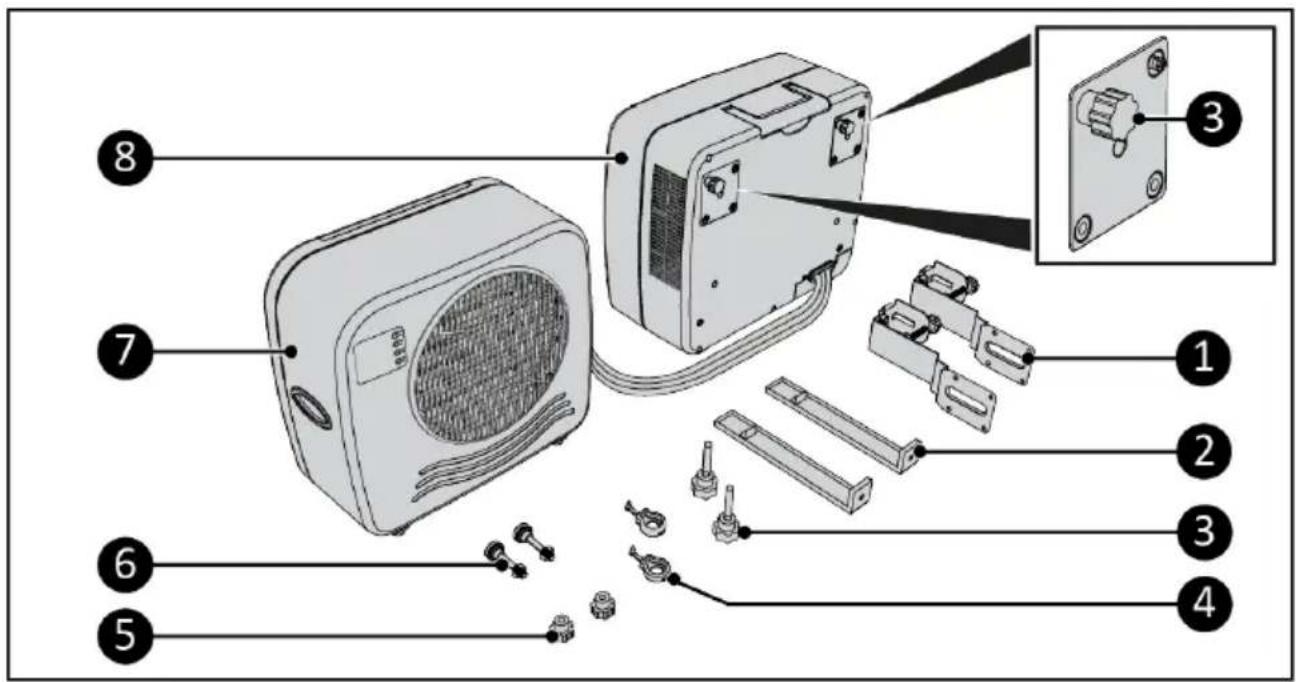
Figure 18.
| No. | Description No. Description | ||
| 1 | Bottom caravan brackets 5 Screw caps | ||
| 2 | Top caravan brackets 6 Adjustment bolts spacer | ||
| 3 | Screw caps (4x) 7 Indoor unit | ||
| 4 | Rubber hooks 8 Outdoor unit |
Control panel and LED display
1.4 hr indication
-
Clock indication
-
Timer button
-
Cool button
-
Speed button
-
ON/OFF button
-
Time indication
-
Power indication
-
High indication
-
Low speed indication
-
High speed indication
-
Cooling level indication
-
Speed level indication
-
0.5 hr indication
-
1 hr indication
-
2 hr indication
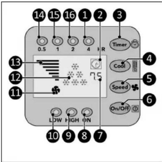
Figure 19.
Transport and storage

CAUTION
Do not leave the device hanging while transporting the caravan or motorhome.

CAUTION
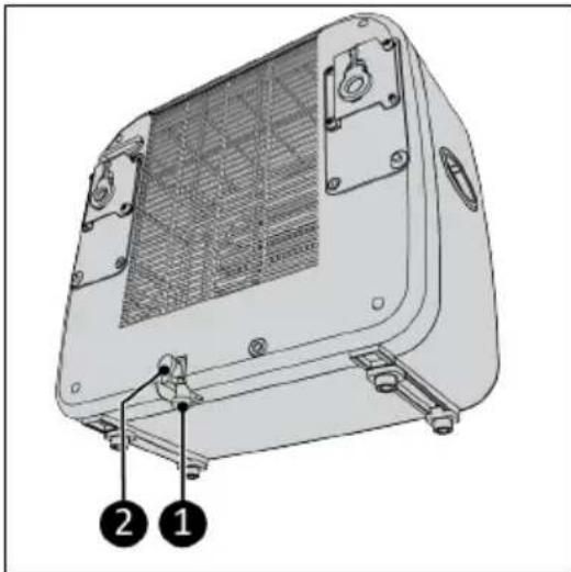
Before moving the indoor unit, first drain the water by removing one of the two sealing caps.
- Clean the device before storing it.
- Transport the device in an upright position.
-
Store the device in an upright position, in its original packaging, in a cool, dry and dust-free area.
-
Remove one of the two sealing caps (Figure 20, pos. 1 or pos. 2).
- Drain the water from the indoor unit.
- Replace the removed sealing cap.
- Make sure two screw caps are mounted on the indoor unit.
- Hook the indoor unit on the outdoor unit for easy transport (Figure 21).
natural_image
Technical line drawing of a portable electronic device with labeled parts (1, 2), showing internal structure and mounting brackets (no text or symbols beyond labels)Figure 20.

Figure 21.
Installation

WARNING
- Do not put the power plug into the wall socket before the device is correctly mounted. Do not use an extension cable; this can cause overheating and fire. If using an extension cable is unavoidable, make sure it is undamaged and earthed. Use an extension cable with a minimum power of 500 Watt. Always unwind the extension cable completely to prevent overheating.

CAUTION
Make sure that the main voltage is the same as indicated on the identification label of the device. All electrical connections must stay dry under all circumstances.
Installation video
- Scan the QR code (Figure 22) to open the video. This video demonstrates the installation of this device.

Figure 22.
Outdoor unit installation
-
Attach the bottom caravan brackets (Figure 23, pos. 2) to the outdoor unit (Figure 23, pos. 1) by tightening two screw caps per bracket (Figure 23, pos. 3).
-
Hang the outdoor unit (Figure 23, pos. 1) in the desired window, make sure the indoor unit is securely placed on a table or couch seat.
-
Tighten the adjustment bolt (Figure 23, pos. 4) per bracket. Make sure the bumper (Figure 23, pos. 5) is placed vertical.
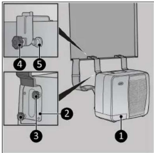
Figure 23.
-
If needed, use the removable block (Figure 24, pos. 4) on thinner walls or window frames.
-
Make sure the outdoor unit (Figure 24, pos. 1) hangs level by tightening the nut (Figure 24, pos. 2) on the adjustment bolt spacer. Make sure the bumper (Figure 24, pos. 3) is placed vertical.
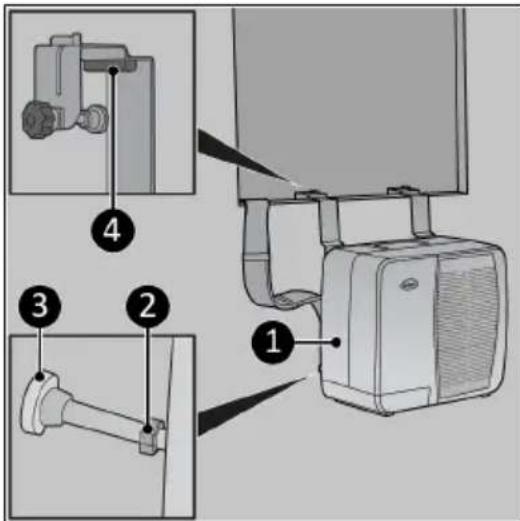
Figure 24.
Indoor unit installation
The indoor unit can be placed on a sturdy table or it can be placed hanging on support brackets.
Support brackets (optional)
- Attach the top caravan brackets (Figure 25, pos. 1) to the bottom caravan brackets by tightening the screw cap per bracket (Figure 25, pos. 2).
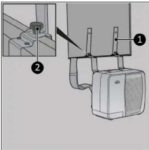
Figure 25.
- Slide the indoor unit over the top caravan brackets (Figure 26, pos. 2).
- To remove the device, lift and slide it in the opposite direction.
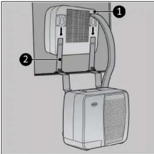
Figure 26.
The rubber hooks (Figure 27, pos. 1) can be used to mount the top caravan brackets to the indoor unit.
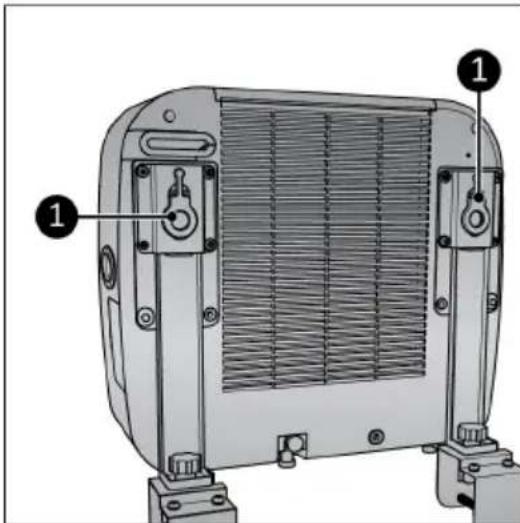
Figure 27.
Operation

WARNING
Before every use, make sure that:
- both sealing caps of the indoor unit are mounted (Figure 20, pos. 1 and 2);
•you operate the device with dry hands;
•the device is clean and dry;
•the device is not damaged;
•the device is not covered or blocked;
•the device stands or hangs securely and horizontally.

CAUTION
The device works at an ambient temperature of max. 42^ C on high speed and max. 38^ C on low speed.
-
Make sure the device is correctly mounted.
-
Place the power plug (Figure 28, pos. 1) into an earthed wall socket that is easily accessible. Use an earthed wall socket with a minimum power of 460 Watt.
-
Three beeps will sound to indicate the device is ready for use.
•Press the ON/OFF button (Figure 28, pos 4), the power indicator (Figure 28, pos. 3) and the high indicator (Figure 28, pos. 2) will light up. The display will show the time indicator and 6 cooling indicators (Figure 28, pos. 5). The device now operates at high capacity.
Speed setting
- Press the Speed button (Figure 29, pos. 1) repeatedly to set the required speed setting:
°High: high indicator (Figure 29, pos. 2) will light up and the speed graph will show 7 bars.
Low: low indicator (Figure 29, pos. 3) will light up and the speed graph will show 4 bars
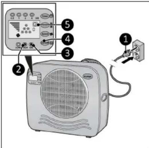
Figure 28.
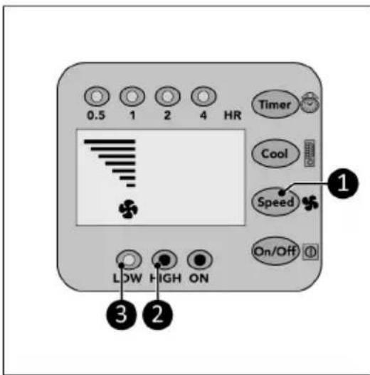
Figure 29.
Cool setting
- Press the Cool button (Figure 30, pos. 1) repeatedly to set the required ambient temperature:
°28 °C, the display will show 1 cool indicator (Figure 30, pos. 4).
°25 °C, the display will show 2 cool indicators (Figure 30, pos. 3).
°22 °C, the display will show 3 cool indicators (Figure 30, pos. 2).
^ <22 ^ C, the display will show 6 cool indicators (Figure 30, pos. 2, 3 and 4).
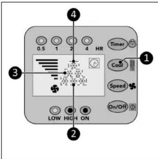
Figure 30.
Timer
At the end of the set countdown timer time the device will automatically switch off.
-
Press the Timer button (Figure 31, pos. 1) repeatedly to start the countdown timer of:
-
0.5 hour: the 0.5 hr indicator (Figure 31, pos. 2) will light up;
°1 hour: the 1 hr indicator (Figure 31, pos. 3) will light up;
°2 hours: the 2 hr indicator (Figure 31, pos. 4) will light up;
°4 hours: the 4 hr indicator (Figure 31, pos. 5) will light up; - 7.5 hours: the 0.5 hr indicator, the 1 hr indicator, the 2 hr indicator and the 4 hr indicator (Figure 31, pos. 2, 3, 4 and 5) will light up.
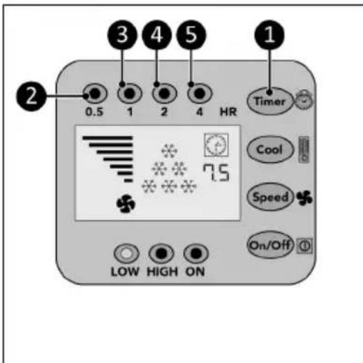
Figure 31.
Drainage of condensed water
Automatic
As soon as the condensate in the collecting tray of the indoor part has reached a certain height (0.8 liter), the pump automatically leads it to the condenser in the outdoor part. In the outdoor unit, the water is partially evaporated with the discharge of the warm air. The remaining water is drained through the drain pipe at the bottom of the outdoor unit.
Manual
In the event of a malfunction of the automatic drainage, you will hear an alarm for 20 seconds and the device will switch off. The water has to be removed manually.
- Remove the plug at the bottom of the indoor unit.
- Connect the supplied drain hose to the bottom of the indoor unit, see Figure 20.
- Turn the device back on. The device can be used in this way temporarily even with a defective pump.
Testing your Caravan air conditioner
*Only available on model AC 5201, not available on model AC 4201.
- Switch on your Caravan air conditioner.
- Set Cool setting : <22 °C, the display will show 6 cool indicators.
- Let the air conditioner cool for 15 minutes.
- HOLD the Cool button and the display shows the temperature of the air blown out by the indoor unit.
- Release the Cool button, display shows 5 seconds the temperature from the incoming air.
- After 5 seconds the display returns to normal function.
Compressor protection function
The compressor protection function gives the compressor a 5-minute delay to protect the device.
After operation

CAUTION
Do not use the power cable to unplug or carry the device. Do not wind the power cable too tightly or in sharp corners. Do not wrap the power cable around the device.
- Make sure the device is switched off and the plug is removed from the power outlet.
- Let the device cool down before touching it.
- Wind the power cable.
- Drain the water from the indoor-unit (Figure 1, pos. 1).
Maintenance

WARNING
Do not perform any repairs or modifications to this device.
Maintenance and repairs must be carried out by a EUROM authorized professional. If the electric cable and/or electric plug is damaged, it should be replaced by the manufacturer or its service employee or persons with similar qualifications to prevent risks.
Cleaning

CAUTION
Do not use:
- scouring pads;
- hard brushes;
- flammable, aggressive or chemical cleaning products.
Prevent water from entering the device. Do not immerse any part of the device in water or other liquids.
It is recommended to clean the device after each use and prior to storage.
- Make sure the device is switched off and the plug is removed from the power outlet.
- Carefully vacuum all openings to remove dust and dirt.
- Wipe the device with a damp, clean, soft, lint-free cloth or a soft brush.
- Let the device dry completely prior to use and storage.
Filter cleaning
- Make sure that:
•the device is switched off; •the plug is removed (Figure 32, pos. 1) from the power outlet.
- Pull the frame up (Figure 32, pos. 2) and remove the filter.
- Carefully vacuum the filter.
- The filter can be cleaned with clean water.
- Let the filter dry completely prior to returning it to its place.
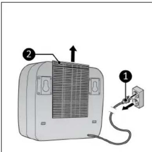
Figure 32.
This marking indicates that this product should not be disposed of with other household waste throughout the EU. To prevent possible harm to the environment or human health from uncontrolled waste disposal, recycle it responsibly to promote the sustainable reuse of material resources. To return your used device, please use the return and collection systems or contact the retailer where the product was purchased. They can take this product for environmentally safe recycling.
Abbildung 34.
natural_image
Technical diagram of a portable electronic device with labeled parts (1, 2), showing internal structure and mounting hardware (no text or symbols beyond labels)Abbildung 36.

Abbildung 37.
Installation

WARNUNG
Abbildung 38.
Abbildung 39.
Abbildung 40.
Abbildung 41.
Abbildung 42.
Abbildung 43.
Betrieb

WARNUNG
Abbildung 44.
Abbildung 48.

Figure 50.
natural_image
Technical diagram of a portable electronic device with labeled parts (1, 2), showing internal structure and mounting hardware (no text or symbols beyond labels)Figure 52.
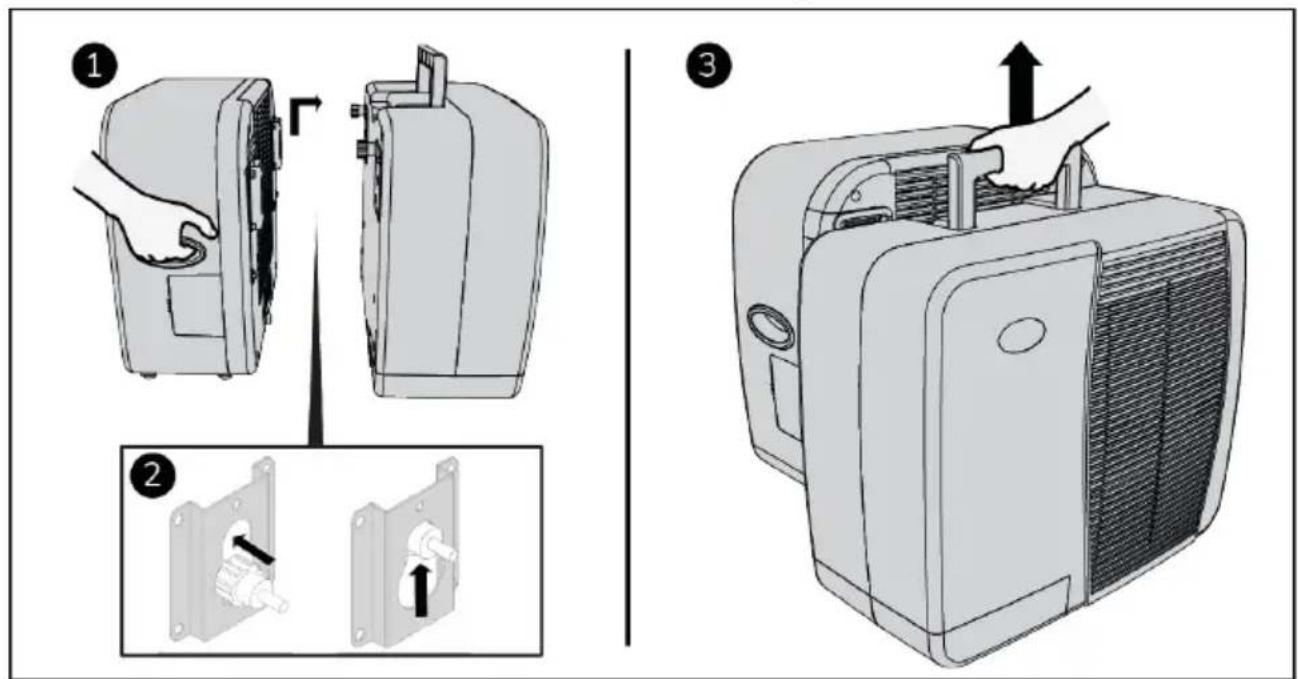
Figure 53.
Installation

AVERTISSEMENT
Figure 54.
Figure 55.
Figure 56.
Figure 57.
Figure 58.
Figure 59.
Utilisation

AVERTISSEMENT
Figure 60.
Réglage de vitesse
Figure 64.
Élimination

natural_image
Symbolic representation of a recycling machine with no text or labelsFigura 66.
natural_image
Technical diagram of a portable electronic device with labeled parts (1, 2), showing internal structure and mounting hardware (no text or symbols beyond labels)Figura 68.

Figura 69.
Installazione

AVVISO
Figura 70.
Figura 71.
Figura 72.
Figura 73.
Figura 74.
Figura 75.
Funzionamento

AVVISO
Figura 76.
Figura 80.
Smaltimento

natural_image
Symbol of recycling with a trash can and a recycling triangle (no text or labels)Figur 82.
natural_image
Technical line drawing of a portable electronic device with labeled parts (1, 2), showing internal structure and mounting brackets (no text or symbols beyond labels)Figur 84.

Figur 85.
Installation

WARNING
Figur 86.
Figur 87.
Figur 88.
Figur 89.
Figur 90.
Figur 91.
Drift

WARNING
Figur 92.
Figur 96.
Avfallshantering

Figur 98.
natural_image
Technical line drawing of a portable electronic device with labeled parts (1, 2), showing internal structure and mounting brackets (no text or symbols beyond labels)Figur 100.

Figur 101.
Installation

ADVARSEL
Figur 102.
Figur 103.
Figur 104.
Figur 105.
Figur 106.
Figur 107.
Betjening

ADVARSEL
Figur 108.
Figur 112.
Bortskaffelse

Kuva 114.
natural_image
Technical diagram of a portable electronic device with labeled parts (1, 2), showing internal structure and mounting hardware (no text or symbols beyond labels)Kuva 116.

Kuva 117.
Asennus

VAROITUS
Kuva 118.
Ulkoyksikön asennus
Kuva 119.
Kuva 120.
Sisäyksikön asennus
Kuva 121.
Kuva 122.
Kuva 123.
Käyttö

VAROITUS
Kuva 124.
Nopeusasetus
Kuva 128.
Hävittäminen

natural_image
Symbol of a recycling bin with a crossed-out paper and a solid recycling triangle (no text or labels)Figure 130.
| Nr. | Beskrivelse Nr. Beskrivelse | ||
| 1 B | Bunnbraketter for campingvogn 5 Skruehetter | ||
| 2 | Toppbraketter for campingvogn 6 Avstandsstykke | for justeringsbolter | |
| 3 | Skruehetter (4x) 7 Innendørsenhet | ||
| 4 | Gummikroker 8 Utendørsenhet | ||
Kontrollpanel og LED-display
natural_image
Technical diagram of a device rear panel with labeled parts (1, 2), showing internal structure and mounting hardware (no text or symbols beyond labels)Figure 132.

Figure 133.
Installasjon

ADVARSEL
Figure 134.
Figure 135.
Figure 136.
Figure 137.
Figure 138.
Figure 139.
Drift

ADVARSEL
Figure 140.
Figure 144.
Avfallshändtering

Obrázek 146.
natural_image
Technical diagram of a portable electronic device with labeled parts (1, 2), showing internal structure and mounting brackets (no text or symbols beyond labels)Obrázek 148.

Obrázek 149.
Instalace

VAROVÁNÍ
Obrázek 150.
Obrázek 151.
Obrázek 152.
Obrázek 153.
Obrázek 154.
Obrázek 155.
Provoz

VAROVÁNÍ
Obrázek 156.
Nastavení rychlosti
Obrázek 160.
Likvidace