NX22 - Electric starter MSW - Free user manual and instructions
Find the device manual for free NX22 MSW in PDF.

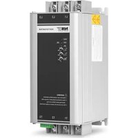
| Product type | Soft starter |
| Model | MSW SOFT STARTER NX22 |
| Rated power | 22 kW |
| Input voltage | 400 V three-phase, 50 Hz |
| Output voltage | 0–400 V three-phase, 50 Hz |
| Rated current | 45 A |
| Main circuit cross-section | 10 mm² |
| Dimensions (W × D × H) | 88 × 118 × 220 mm |
| Weight | 1.8 kg |
| Protection rating | IP20 |
| Operating temperature | -25 °C to +60 °C |
| Storage temperature | -40 °C to +70 °C |
| Motor overload | Class 10 |
| Standard | EN 60947-4-2 |
| Main functions | Soft start, soft stop, overcurrent protection, overload, underload, phase imbalance, overheating |
| Maintenance | Regular dust cleaning, connection inspection, ventilation maintenance |
| Safety | Disconnect before intervention, use by qualified electrician, do not touch when energized |
| Spare parts | Available on request from the manufacturer |
| Repairability | Repairs by manufacturer service only |
| Intended use | Acceleration control of three-phase motors (pumps, fans, conveyors) |
Frequently Asked Questions - NX22 MSW
User questions about NX22 MSW
0 question about this device. Answer the ones you know or ask your own.
Ask a new question about this device
Download the instructions for your Electric starter in PDF format for free! Find your manual NX22 - MSW and take your electronic device back in hand. On this page are published all the documents necessary for the use of your device. NX22 by MSW.
USER MANUAL NX22 MSW
natural_image
Diagram of an electronic device rear panel showing internal components and connectors (no text or symbols)1- LAUFEN
2- COM
3- STOPP
4- RA
5- RB
line
| t | U | | --- | ---- | | 0 | 0 | | 1 | 100% | | 2 | 100% | | 3 | 0 |This User Manual has been translated using machine translation. We have made every effort to ensure the translation is accurate, but please note that automated translations are not perfect and are not meant to replace human translators. The official version of the User Manual is in English. Any differences between the translated version and the original English are not legally binding. If you have any questions about the accuracy of the translation, please refer to the English version, which is the official reference. More language versions are available upon request via info@expondo.com.
Technical data
| Parameter description | Parameter value | ||
| Product name | Soft starter | ||
| Model | MSW SOFT STARTER NX22 | MSW SOFT STARTER SST-NX11 | MSW SOFT STARTER SST-NX5R5 |
| Power [kW] | 22 | 11 | 5.5 |
| V input [V, N~ / Hz] | 400, 3~/ 50 | ||
| V output [V, N~ / Hz] | 0-400, 3~ / 50 | ||
| I input [A] | 45 | 25 | 13 |
| Main circuit dia [mm2] | 10 | 4 | 2.5 |
| Working temp [°C] | -25~60 | ||
| Storage temp [°C] | -40~70 | ||
| Motor overload | Class 10 | ||
| Standard | EN60947-4-2 | ||
| Protection grade | IP20 | ||
| Dimensions [width x length x height; mm] | 88 x 118 x 220 | ||
| Weight [kg] | 1.8 | 1.7 | 1.7 |
1. General description
The user manual is designed to assist in the safe and trouble-free use of the device. The product is designed and manufactured in accordance with strict technical guidelines, using state-of-the-art technologies and components. Additionally, it is produced in compliance with the most stringent quality standards.
DO NOT USE THE DEVICE UNLESS YOU HAVE THOROUGHLY READ AND UNDERSTOOD THIS USER MANUAL.
To increase the product life of the device and to ensure trouble-free operation, use it in accordance with this user manual and regularly perform maintenance tasks. The technical data and specifications in this user manual are up to date. The manufacturer reserves the right to make changes associated with quality improvement. The device is designed to reduce noise emission risks to a minimum, taking into account technological progress and noise reduction opportunities.
Legend

The product satisfies the relevant safety standards.
Read instructions before use.
The product must be recycled.
WARNING! or CAUTION! or REMEMBER! Applicable to the given situation. (general warning sign)

ATTENTION! Electric shock warning!

PLEASE NOTE! Drawings in this manual are for illustration purposes only and in some details may differ from the actual product.
2. Usage safety

ATTENTION! Read all safety warnings and all instructions. Failure to follow the warnings and instructions may result in electric shock, fire and/or serious injury or even death.
The terms "device" or "product" are used in the warnings and instructions to refer to: Soft starter
2.1. Electrical safety
a) The plug must fit the socket. Do not modify the plug in any way. Using original plugs and matching sockets reduces the risk of electric shock.
b) Avoid touching earthed elements such as pipes, heaters, boilers and refrigerators. There is an increased risk of electric shock if the earthed device is exposed to rain, comes into direct contact with a wet surface or is operating in a damp environment. Water getting into the device increases the risk of damage to the device and of electric shock.
c) Do not touch the device with wet or damp hands.
d) Use the cable only for its designated use. Never use it to carry the device or to pull the plug out of a socket. Keep the cable away from heat sources, oil, sharp edges or moving parts. Damaged or tangled cables increase the risk of electric shock.
e) If working with the device outdoors, make sure to use an extension cord suitable for outdoor use. Using an extension cord suitable for outdoor use reduces the risk of electric shock.
f) If using the device in a damp environment cannot be avoided, a residual current device (RCD) should be applied. The use of an RCD reduces the risk of electric shock.
g) Do not use the device if the power cord is damaged or shows obvious signs of wear. A damaged power cord should be replaced by a qualified electrician or the manufacturer's service centre.
h) To avoid electric shock, do not immerse the cord, plug or device in water or other liquids. Do not use the device on wet surfaces.
i) ATTENTION! DANGER TO LIFE! While cleaning, never immerse the device in water or other liquids.
j) Do not use in very humid environments or in the direct vicinity of water tanks.
k) Prevent the device from getting wet. Risk of electric shock!
2.2. Safety in the workplace
a) Make sure the workplace is clean and well lit. A messy or poorly lit workplace may lead to accidents. Try to think ahead, observe what is going on and use common sense when working with the device.
b) Do not use the device in a potentially explosive environment, for example in the presence of flammable liquids, gases or dust. The device generates sparks which may ignite dust or fumes.
c) If you discover damage or irregular operation, immediately switch the device off and report it to a supervisor without delay.
d) If you are unsure about whether the device is operating correctly or if you find damage, please contact the manufacturer's service centre.
e) Only the manufacturer's service centre may make repairs to the device. Do not attempt to make repairs yourself!
f) In case of fire, use a powder or carbon dioxide (CO _2 ) fire extinguisher (one intended for use on live electrical devices) to put it out.
g) Children or unauthorised persons are forbidden to enter a work station. A distraction may result in loss of control over the device.
h) Regularly inspect the condition of the safety labels. If the labels are illegible, they must be replaced.
i) Please keep this manual available for future reference. If this device is passed on to a third party, the manual must be passed on with it.
j) Keep packaging elements and small assembly parts in a place not available to children.
k) Keep the device away from children and animals.

Remember! When using the device, protect children and other bystanders.
2.3. Personal safety
a) Do not use the device when tired, ill or under the influence of alcohol, narcotics or medication which can significantly impair the ability to operate the device.
b) The device should be operated by qualified electricians as per safety specifications, including installation, pilot run and maintenance, etc.
c) The device is not designed to be handled by persons (including children) with limited mental and sensory functions or persons lacking relevant experience and/or knowledge unless they are supervised by a person responsible for their safety or they have received instruction on how to operate the device.
d) The device can be handled only by physically fit persons who are capable of handling it, properly trained, familiar with this manual and trained within the scope of occupational health and safety.
e) When working with the device, use common sense and stay alert. Temporary loss of concentration while using the device may lead to serious injuries.
f) Use personal protective equipment as required for working with the device, specified in section 1 "Legend". The use of correct and approved personal protective equipment reduces the risk of injury.
g) To prevent the device from accidentally switching on, make sure the switch is on the OFF position before connecting to a power source.
h) Do not overestimate your abilities. When using the device, keep your balance and remain stable at all times. This will ensure better control over the device in unexpected situations.
i) The device is not a toy. Children must be supervised to ensure that they do not play with the device.
j) Do not put your hands or other items inside the device while it is in use!
2.4. Safe device use
a) Do not overload the device. Use the appropriate tools for the given task. A correctly-selected device will perform the task for which it was designed better and in a safer manner.
b) The voltage used by the product is dangerous, which may cause serious injury or death of others. Prohibit touching terminal after electrifying the device or during operation. Although the device is switched off, voltage may still exist in output terminal.
c) The device should be used under rated specification of product. Before use, please check the accuracy of various parameters such as power motor and frequency of product or device.
d) The device has passed insulation test before leaving factory. Incorrect megger test may damage product or shorten product life.
e) It is strictly forbidden to connect strong electricity in secondary lines such as RUN and COM. Secondary terminal power supply can cause damage to the main board.
f) Do not use the device if the "ON/OFF" switch does not function properly (does not switch the device on and off). Devices which cannot be switched on and off using the "ON/OFF" switch are hazardous, should not be operated and must be repaired.
g) Make sure the plug is disconnected from the socket before attempting any adjustments, accessory replacements or before putting the device aside. Such precautions will reduce the risk of accidentally activating the device.
h) Disconnect the device from the power supply before commencement of adjustment, cleaning and maintenance. Such a preventive measure reduces the risk of accidental activation.
i) When not in use, store in a safe place, away from children and people not familiar with the device who have not read the user manual. The device may pose a hazard in the hands of inexperienced users.
j) Keep the device in perfect technical condition. Before each use check for general damage, especially check moving components for cracked parts or elements, and for any other conditions which may impact the safe operation of the device. If damage is discovered, hand over the device for repair before use.
k) Keep the device out of the reach of children.
I) Device repair or maintenance should be carried out by qualified persons, only using original spare parts. This will ensure safe use.
m) To ensure the operational integrity of the device, do not remove factory-fitted guards and do not loosen any screws.
n) When transporting and handling the device between the warehouse and the destination, observe the occupational health and safety principles for manual transport operations which apply in the country where the device will be used.
o) Avoid situations where the device stops working during use due to excessive loading. This may result in overheating of the drive elements and damage to the device.
p) Do not touch articulated parts or accessories unless the device has been disconnected from the power source.
q) Do not move, adjust or rotate the device in the course of work.
r) Do not leave this appliance unattended while it is in use.
s) Clean the device regularly to prevent stubborn grime from accumulating.
t) Do not carry or hang the device by the pressure line.
u) It is forbidden to interfere with the structure of the device in order to change its parameters or construction.
v) Keep the device away from sources of fire and heat.
w) Do not overload the device.
x) Do not cover the ventilation openings!

ATTENTION! Despite the safe design of the device and its protective features, and despite the use of additional elements protecting the operator, there is still a slight risk of accident or injury when using the device. Stay alert and use common sense when using the device.
3. Use guidelines
The product is an electronic device used to control the acceleration of an electric motor, helping to reduce the mechanical stress and electrical current surge that occurs when a motor starts. By gradually increasing the voltage supplied to the motor, the device allows for a smooth and controlled start-up, extending the lifespan of the motor and reducing wear on mechanical components. It is commonly employed in industrial applications where large motors are used, such as in pumps, fans, and conveyors, to ensure a more energy-efficient and reliable operation.
The user is liable for any damage resulting from unintended use of the device.
3.1. Device description
Terminal Description
1- RUN
2- COM
3- STOP
4- RA
5- RB
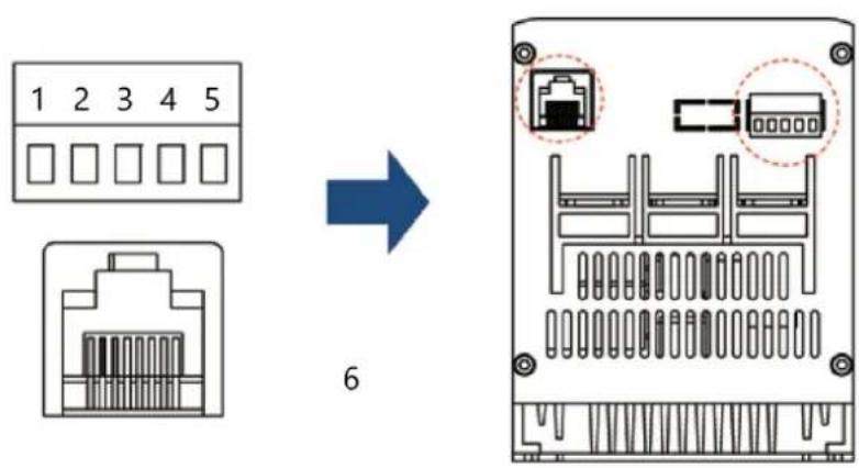
6- For external panel only
Control Loop
| Terminal Marking | Terminal Name Function | |
| RUN Enable input | When RUN and COM are closed, the motor starts to run; when disconnected, the motor decelerates and stops (only two-wire control (default); if necessary, please contact the manufacturer. | |
| COM | Common port | For Run and Stop |
| STOP Stop input | The motor stops when STOP and COM are closed (only three-wire control) | |
| RA, RB | Indication of working status | Working status: relay output, normally open contact, closed during operation, open during shutdown or failure, relay capacity 250V/AC 0.3A |
| Terminal Marking | Terminal Name | Function |
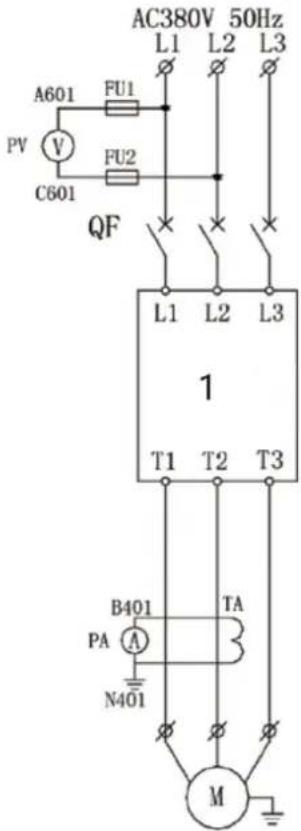
| L1/L2/L3 | Mains input of major loop | Connect three-phase source |
| T1/T2/T3 | Output connection of soft start | Connect three-phase motor |
Major Loop
3.2. Preparing for use
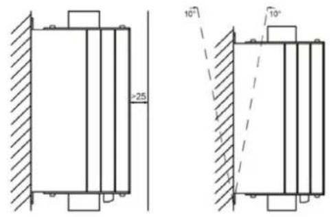
Permissible Ambient Environment
The device can operate in ambient temperatures ranging from -25^ to +60^ . If the ambient temperature exceeds 40^ , the device's rated current will decrease by 1% for every 1^ increase.
The device can be stored in conditions ranging from -40°C to +70°C.
Install Sketch
3.3. Device use
Parameter Settings
Panel Parameters
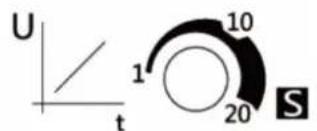
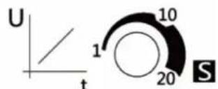
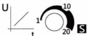
Knob of soft start time: used to adjust the soft start time. The range is 1\~20s. The longer the time is set, the smoother the soft start process will be, which is beneficial to reduce the impact on the power grid.
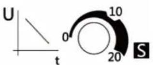
Knob of soft stop time: used to adjust the soft stop time, the range is 0\~20s. The soft stop function can effectively avoid the “water hammer effect” when the pump stops in some pump applications. When the knob is adjusted to 0s, it means that the motor parking mode is the free parking mode, and the soft start stops the output immediately.

Knob of starting voltage: used to adjust the starting voltage. The range is 40%\~70%. When starting, the motor needs to overcome the friction force in the static state. Properly increase the starting voltage to
obtain a larger starting torque. The user should refer to the actual load situation and cooperate with the start and stop time to obtain the best smooth start effect.
line
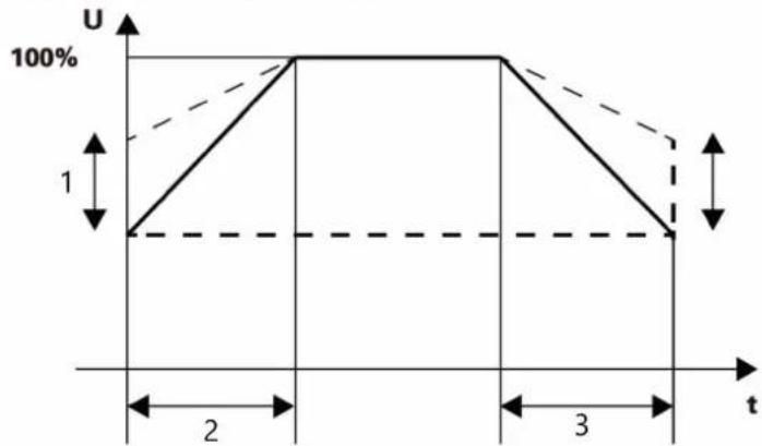
| t | U | | --- | ---- | | 0 | 0 | | 1 | 100% | | 2 | 100% | | 3 | 0 |1- Initial voltage
2- Start Slope
3- Stop Slope
Operation sequence diagram
line
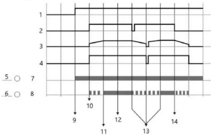
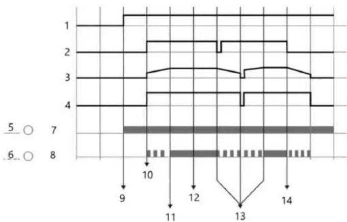
| Time | Value | |------|-------| | 1 | 1 | | 2 | 2 | | 3 | 3 | | 4 | 4 | | 5 | 5 | | 6 | 6 | | 7 | 7 | | 8 | 8 | | 9 | 9 | | 10 | 10 | | 11 | 11 | | 12 | 12 | | 13 | 13 | | 14 | 14 |1- Power
2- Start/Stop signal
3- Motor voltage
4- Run output
5- On
6- LED1
7- RUN
8- LED2
9- Apply main voltage
10- Start command
11- Finish starting
12- Bypass operation
13- Restart after stalling midway
14- Stop command
Indicator light
| RUN | Steady lighting | Flashing | Off |
| Steady lighting | Bypass operation | Input or output phase loss/ hardware malfunction | Hardware malfunction |
| Flashing | Soft start / stop in progress | Hardware malfunction Hardware malfunction | |
| Off | The device is ready for power on | Input or output phase loss / Motor not connected | Soft start power failure / Indicator failure |
| FAULT | Fault | - | No Fault |
Power Diagram
| Model | 230V/kW | 400V/kW | Rated current(A) |
| NX5R5 | 3 | 5.5 | 13 |
| NX11 | 5.5 | 11 | 25 |
| NX22 | 11 | 22 | 45 |
Keyboard setting
This is an optional accessory (not included in the standard product) and is connected through the RJ45 interface (network cable required). If need it, please contact the manufacturer.
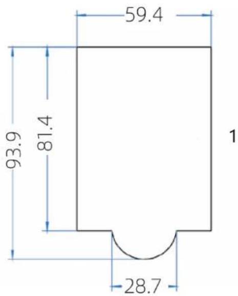
1- Panel Size
Setting-up process
- Start setting up.
- First, connect the main power supply of L1-L3, and check Power-on Reset for the soft starter. For the first time use, a power-on reset must be carried out, in case there is uncompleted commands. At this stage, output terminal T2 is electriferous, so please pay attention to safe operation.
- Disconnect the main power supply and connect the output terminals with three-phase motor.
- After connecting the motor, the ON light is flashing and turns into a steady lighting. If it keeps flashing, please check the line and do not perform subsequent steps.
- Prestart the motor by terminals RUN and COM.
6. Two following processes
A. Raise the starting voltage if the motor has a delaying rotation.
B. Lower the starting voltage or extend start-up time if the rotation of the motor is too fast.
-
Adjust starting voltage, starting time and soft stopping time to obtain optimum effect, after which step the setting-up process is completed.
-
Setting up is completed.
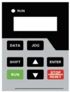
Button Description
| Button | Name | Function |
| DATA | Programming Button | Enter or exit the first level menu |
| JOG | Jog Button | Jog running motor (for testing only) |
| ▲ | Increment | Increment of data or function code |
| ▼ | Decrement | Decrement of data or function code |
| SHIFT | Shift | In the stop and running display interface, the display parameters can be selected cyclically; when changing the parameters, the modification position can be selected |
| ENTER | Enter | Enter the menu screen step by step, and set the parameters to confirm |
| RUN | Run | In the keyboard operation mode, used for running operation |
| STOP/ RESET | Stop/Reset | When running, this button can be used to stop running operation; in fault alarm state; used to reset operation |
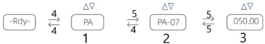
Code view and modification method description
flowchart
graph LR
    A["-Rdy-"] -->|4| B["PA"]
    B -->|5| C["PA-07"]
    C -->|5| D["050.00"]
    B -->|4| E["1"]
    C -->|2| F["2"]
    D -->|3| G["3"]
1- Level 1
2- Level 2
3- Level 3
4- DATA
5- ENTER
The operation panel adopts a three-level menu structure. Function parameter group (level 1 menu) → function code (level 2 menu) → function code setting value (level 3 menu). Note: When operating in the third-level menu, press the DATA or ENTER to return to the second-level menu. The difference is: press the ENTER to save the set parameters and return to the secondary menu, and automatically transfer to the next function code; while pressing the DATA will directly return to the secondary menu without storing the parameters and return to the current function code.
| Code Name | OverloadMultipleDuring SoftStart | SettingRange1.0 - 5.0 5.0 | Default Description | The soft-start process is based onthe overload multiple of the ratedload current, and its value is setaccording to the weight of the load. |
| PA-03 | ||||
| PA-04 | Rated PowerOperationOverloadMultiple | 1.0 - 2.0 1.5 | Based on the rated power current,this setting determines the overloadmultiple during normal operation,which is adjusted according to siteconditions. | |
| PA-05 | OverloadDelay DuringSoft Start | 1 - 250 10 | This delay time (in seconds) afterexceeding the rated currentoverload multiple during the soft-start process is set based on siteconditions. | |
| PA-06 | Rated PowerOperationOverloadDelay | 1 - 20 min | 5 min | This parameter sets the delay (inminutes) of overload time afterexceeding the rated power currentoverload multiple during theoperation of the soft starter. |
| PA-07 | MotorUnderloadProtection | 0 - 100% 20% | The current setting range forunderload protection can be up to100%; when set to 0, this protectionis invalid. | |
| PA-08 | MotorUnderloadProtectionDelay | 1 - 20 min | 5 min | This parameter sets the delay time(in minutes) for underloadprotection. |
| PA-09 | Protection Off | 0 - 250 | 0 | This parameter is used to disable theprotection function. If you need todisable a specific protectionfunction, set the correspondingposition in the binary table below as1, convert the binary value intodecimal, and set it in PA-09. Thisparameter will disable theprotection; please use it withcaution. |
| PA-11 | Operationcontrol modeselection | 0/1/2 0 | Operation control mode selection: 0.Terminal control (two-wire system);1. Terminal control (three-wiresystem); 2. Panel control | |
| PA-15 | Restoredefault | 0/1 0 | Restore default: 0. Invalid; 1. Restoredefault value |
| Bit7 | Bit6 | Bit5 | Bit4 | Bit3 | Bit2 | Bit1 | Bit0 |
| Under load | Function reserved | Function reserved | Function reserved | 3-phase unbalance (Phase loss) | Overheat | Overload Overcurrent | |
| 0 | 0 | 0 | 0 | 0 | 0 | 0 | 0 |
Example: If the overcurrent and overheat protection needs to be turned off, the binary code "00000101" is converted to the corresponding decimal "5".
Error Code
| Error code | Fault name |
| Err01 | Overcurrent fault |
| Err02 | Overload fault |
| Err03 | Overheating fault |
| Err04 | Output three-phase unbalanced |
| Err05 | A-Phase current sensor failure |
| Err06 | C-Phase current sensor failure |
| Err07 | Host failure |
| Err08 | Underload fault |
| Err09 | Arrears (exceeding the set number of runs) |
3.4. Cleaning and maintenance
a) Regularly inspect the device to ensure it's clean and free from any dirt or corrosion. Use a soft brush or a damp cloth to gently remove any dust or debris.
b) Ensure that there is no obstruction around the soft starter that could impede proper ventilation and heat dissipation. Maintain necessary clearance around the device to promote good airflow.
c) Regularly check the electronic components and wiring inside the device. Look for signs of wear or damage such as leaking capacitors, short-circuited resistors, or poorly connected relays. Replace any damaged components as needed.
d) Dust accumulation can lower the insulation level and lead to overheating. Clean the dust inside the device using a dry brush or compressed air. For more stubborn debris, an insulating rod or controlled air spray may be used.
e) Adjust the starting parameters based on the motor's load conditions and protective characteristics of the grid relay. This helps manage the starting current effectively and prevents equipment damage due to overload impacts.
f) Employ a structured schedule for preventive maintenance based on the device's operating conditions and guidelines. This includes periodic checks of settings, recording of operational data like start periods, fault codes, and overall performance assessments.
DISPOSING OF USED DEVICES:
Do not dispose of this device in municipal waste systems. Hand it over to an electric and electrical device recycling and collection point. Check the symbol on the product, instruction manual and packaging. The plastics used to construct the device can be recycled in accordance with their markings. By choosing to recycle you are making a significant contribution to the protection of our environment.
Contact local authorities for information on your local recycling facility.
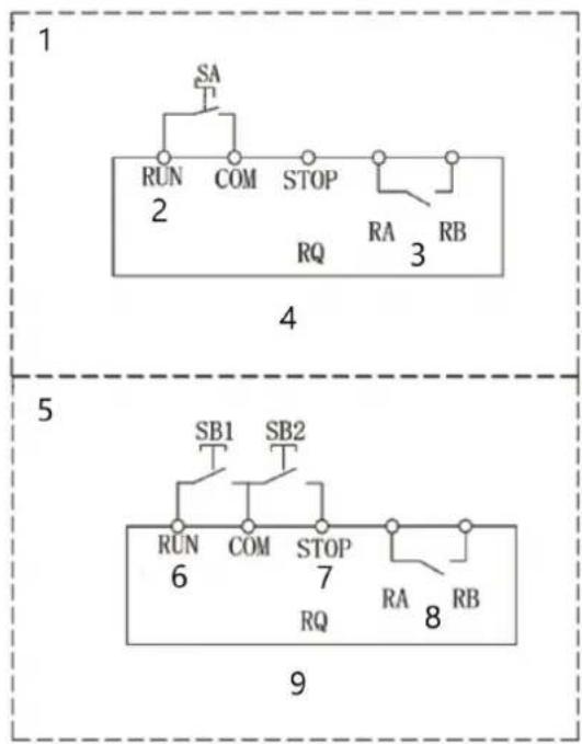
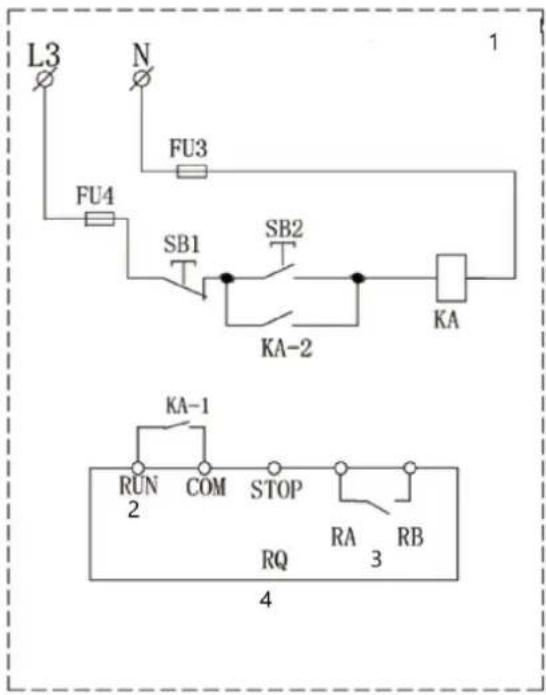
WIRING DIAGRAM
The drawings below are for reference only.
flowchart
graph TD
    subgraph 1
        A["SA"] --> B["RUN"]
        B --> C["COM"]
        C --> D["STOP"]
        D --> E["RA"]
        E --> F["RB"]
        G["2"] --> H["RQ"]
    end
    subgraph 5
        I["SB1"] --> J["RUN"]
        J --> K["COM"]
        K --> L["STOP"]
        L --> M["RA"]
        M --> N["RB"]
        O["6"] --> P["RQ"]
    end
    subgraph 9
        Q["SB2"] --> R["RUN"]
        R --> S["COM"]
        S --> T["STOP"]
        T --> U["RA"]
        U --> V["RB"]
-
Two-wire control
-
Start input
-
Work status indicator
-
Knob/switch (self-locking type)
-
Three-wire control
-
Start input
-
Stop input
-
Work status indicator
-
Button start and stop mode (Set PA-11=1)
-
Two-wire control
-
Start input
-
Work status indicator
-
Button start and stop mode
1- Soft starter

line
| t | U | | --- | ---- | | 0 | 0 | | 1 | 100% | | 2 | 100% | | 3 | 0 |line
| t | U | | --- | ---- | | 1 | 1 | | 2 | 100% | | 3 | 100% |1- Počáteční napětí
2- Start Slope
3- Stop Slope
natural_image
Diagram of an electronic device rear panel showing internal components and connectors (no text or symbols)1- COURIR
2- COM
3- ARRÊT
4- RA
5- RB
line
| t | U | | --- | ---- | | 1 | 1 | | 2 | 100% | | 3 | 100% |line
| t | U | | --- | ---- | | 0 | 1 | | 1 | 100% | | 2 | 100% | | 3 | 100% |line
| t | U | | --- | ---- | | 0 | 0 | | 1 | 100% | | 2 | 100% | | 3 | 0 |line
| t | U | | --- | ---- | | 0 | 1 | | 2 | 100% | | 3 | 100% | | 4 | 1 |line
| t | U | | --- | ---- | | 0 | 1 | | 2 | 100% | | 3 | 100% |line
| t | U | | --- | ---- | | 1 | 0 | | 2 | 100% | | 3 | 100% |1- Alkujännite
2- Aloita kaltevuus
3- Pysäytä Slope
line
| t | U | | --- | ---- | | 0 | 0 | | 1 | 100% | | 2 | 100% | | 3 | 0 |1- Beginspanning
2- Starthelling
3- Stophelling
line
| t | U | | --- | ---- | | 0 | 0 | | 1 | 100% | | 2 | 100% | | 3 | 0 |1- Startspenning
2- Start Slope
3- Stopp Slope
natural_image
Diagram of an electronic device rear panel showing internal components and connectors (no text or symbols)line
| t | U | | --- | ---- | | 0 | 0 | | 1 | 100% | | 2 | 100% | | 3 | 100% |1- Initial spänning
2- Starta Slope
3- Stoppa Slope
line
| t | U | | --- | ---- | | 0 | 0 | | 1 | 100% | | 2 | 100% | | 3 | 100% |1- Tensão inicial
line
| t | U | | --- | ---- | | 0 | 0 | | 1 | 100% | | 2 | 100% | | 3 | 100% |natural_image
Diagram of an electronic device rear panel showing internal components and connectors (no text or symbols)line
| t | U | | --- | ---- | | 0 | 0 | | 1 | 100% | | 2 | 100% | | 3 | 0 |natural_image
Diagram of an electronic device rear panel showing internal components and connectors (no text or symbols)3.3. Χρήση συσκευής
line
| t | U | | --- | ---- | | 0 | 0 | | 1 | 100% | | 2 | 100% | | 3 | 0 |3.3. Upotreba uređaja
Postavke parametara
Parametri ploče
line
| t | U | | --- | ---- | | 1 | 0 | | 2 | 100% | | 3 | 100% |1- Početni napon
2- Početak nagiba
3- Zaustavi nagib
line
| t | U | | --- | ---- | | 1 | 0 | | 2 | 100% | | 3 | 100% |1- Pradinė įtampa
2- Pradėti nuolydį
3- Stop Slope
Operaciju sekos schema
line
| Time | Value | |------|-------| | 9 | 1 | | 10 | 10 | | 11 | 11 | | 12 | 12 | | 13 | 13 | | 14 | 14 |1- Galia
2- Start/Stop signalas
3- Variklio jtampa
4- Paleisti išvestj
5- Ijungta
6- LED1
7- BÈGTI
8- LED2
line
| t | U | | --- | ---- | | 0 | 0 | | 2 | 100% | | 3 | 100% |3.3. Uporaba naprave
Nastavitve parametrov
Parametri plošče
line
| t | U | | --- | ---- | | 1 | 0 | | 2 | 100% | | 3 | 100% |For the disposal of the device please consider and act according to the national and local rules and regulations.
CONTACT
expondo Polska sp. z o.o. sp. k.