
Raceline Pedals LTE - Controller THRUSTMASTER - Free user manual and instructions
Find the device manual for free Raceline Pedals LTE THRUSTMASTER in PDF.

User questions about Raceline Pedals LTE THRUSTMASTER
0 question about this device. Answer the ones you know or ask your own.
Ask a new question about this device
Download the instructions for your Controller in PDF format for free! Find your manual Raceline Pedals LTE - THRUSTMASTER and take your electronic device back in hand. On this page are published all the documents necessary for the use of your device. Raceline Pedals LTE by THRUSTMASTER.
USER MANUAL Raceline Pedals LTE THRUSTMASTER
Carefully read the instructions provided in this manual before installing the product, before any use of the product and before any maintenance. Be sure to follow the safety instructions. Failure to follow these instructions may result in accidents and/or damage. Keep this manual so that you can refer to the instructions in the future.
TABLE OF CONTENTS
-
BOX CONTENTS ....4
-
FEATURES......6
-
INFORMATION REGARDING USE 8
-
ASSEMBLY....12
-
INSTALLATION......20
Compatibility....22
- PEDAL SET MECHANICAL SETTINGS .....23
Adjusting the height of the pedals ...... 23
Modifying the brake pedal's resistance...25
Modifying the accelerator pedal's resistance....28
- CARPET GRIP NON-SLIP SUPPORTS .....30
Assembly....31
Disassembly....32
- FAQ AND TECHNICAL SUPPORT ......33
RACELINE PEDALS LTE
LONG TERM EVOLUTION
Raceline Pedals LTE, featuring two pedals with H.E.A.R.T. sensors, is the ideal pedal set to help improve your car racing simulation performance.
This manual will help you install and use your Raceline Pedals LTE under the best conditions. Before getting started racing, carefully read the instructions and the warnings: they will help you get the most enjoyment out of your product.
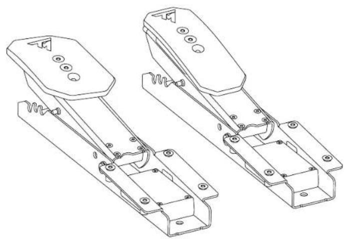
1. Box contents
natural_image
Technical line drawing of two mechanical device components with mounting holes and spring-like brackets (no text or symbols)
natural_image
Line drawing of a rectangular metal plate with evenly spaced circular holes (no text or symbols)
natural_image
Pure mechanical assembly diagram showing a valve, spring, and housing (no text or symbols)
natural_image
Pure mechanical component diagram without any text, numbers, or symbols

natural_image
Simple electrical circuit diagram with a bulb, capacitor, and two labeled terminals (G and B) connected by wires (no text or symbols beyond labels)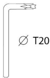

natural_image
Isometric view of a 3D rectangular block with spiral grooves and a side label 'x 2' (no text or symbols on the object itself)

2. Features


natural_image
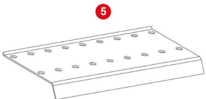
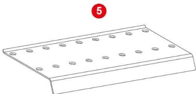
Line drawing of a rectangular metal plate with evenly spaced circular holes, labeled with number 5 (no text or symbols on the plate itself)1 Brake pedal
② Accelerator pedal
③ Brake pedal jack connector
4 Accelerator pedal jack connector
5 Footrest
x 8
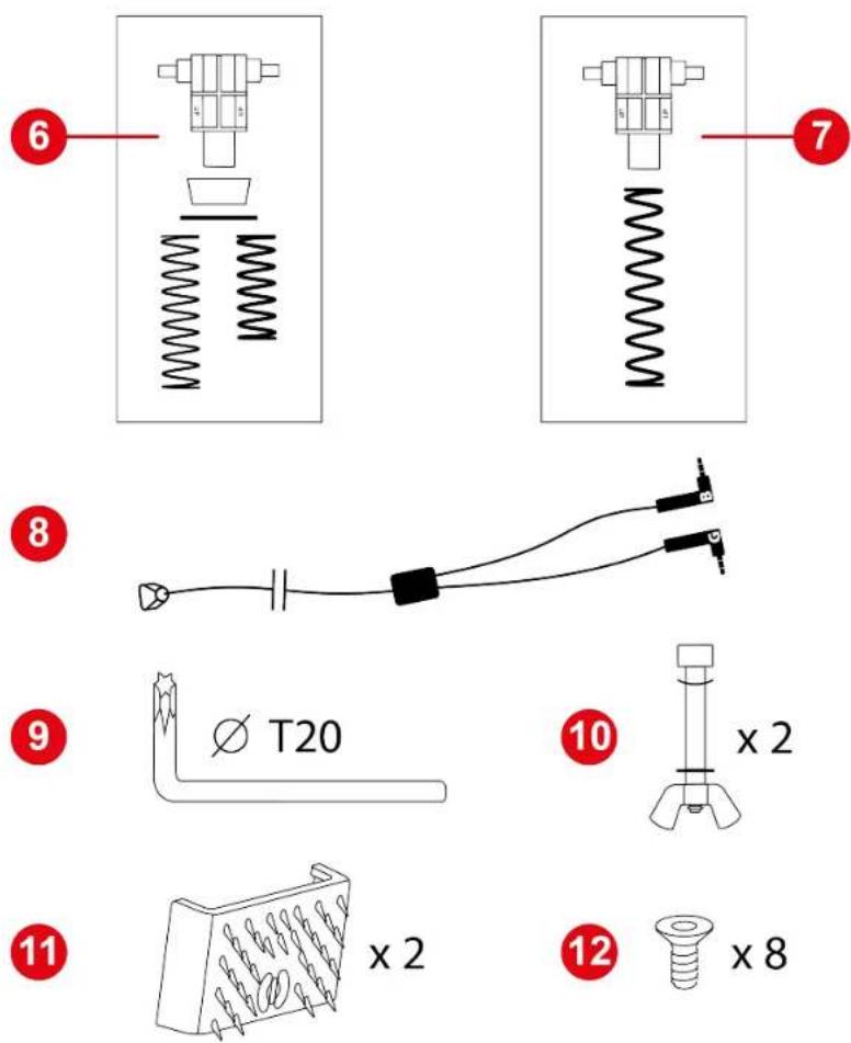
6 Brake pedal spring (one support, one buffer, one washer and two springs (weak or strong resistance))
7 Accelerator pedal spring (one support and one spring)
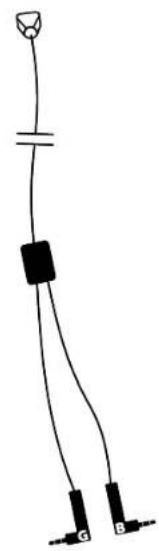
8 Double jack/RJ12 cable
9 T20 Torx wrench
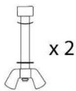
10 Pedal stop rods (one rod, one wing nut, one curved washer and one washer)
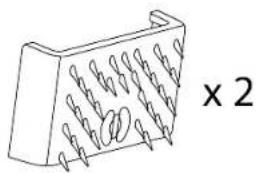
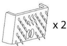
11 Carpet Grip non-slip supports
12 Screws
3. Information regarding use

Documentation
Before using this product, carefully read this documentation again and keep it for future reference.

For safety reasons, never use the pedal set with bare feet or while wearing only socks on your feet. Thrustmaster® disclaims all responsibility in the event of injury resulting from use of the pedal set without shoes.


Product to be handled only by people 16 years of age or older.

Electrical shock
- Keep the product in a dry location and do not expose it to dust or sunlight.
- Do not twist or pull on the connectors and cables.
- Follow the connection directions.
- Do not spill any liquid on the product or its connectors.
- Do not short-circuit the product.
- Never dismantle the product; do not throw it onto a fire and do not expose it to high temperatures.

Injuries due to repeated movements
Playing with a pedal set may cause muscle or joint pain.
To avoid any problems:
- Avoid overly-long gaming periods (more than 2 hours).
- Take a 10 to 15-minute break after each hour of play.
- If you feel any fatigue or pain in your feet or legs, stop playing and rest for a few hours before you start playing again.
- If the symptoms or pain indicated above persist when you start playing again, stop playing and consult your doctor.

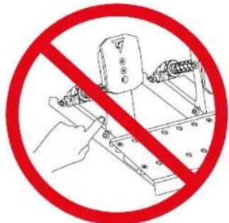
Pedal set pinch hazard when playing
- Keep the pedal set out of children's reach.
- During gaming sessions, never place your fingers (or other parts of your body) on or near the pedal arms.
4. Assembly

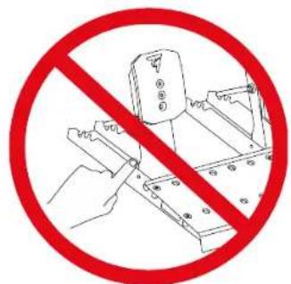
Pinch hazard
Before assembling the pedal set, make sure your fingers are not between the pedal arms and the base of the pedal set when lowering the pedals.
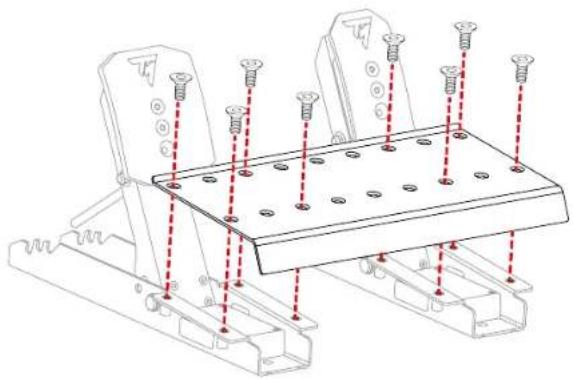
- Using the included T20 Torx wrench and screws, attach the footrest to the two pedals.
The brake pedal is on the left. The accelerator pedal is on the right.
natural_image
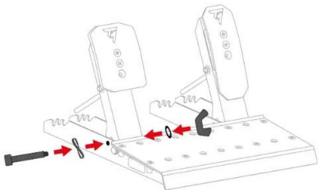
Technical line drawing of a mechanical support structure with mounting holes and red dashed lines indicating assembly points (no text or symbols present)- Insert the stop rod into the corresponding perforations in the base of the pedal set: the rod and the curved washer on one side of the pedal, the washer and wing nut on the other side.
Repeat the procedure on the other pedal.
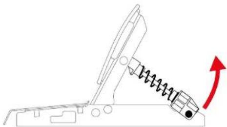
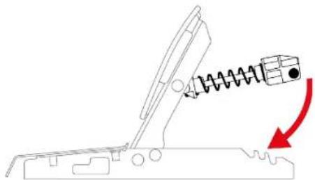
natural_image
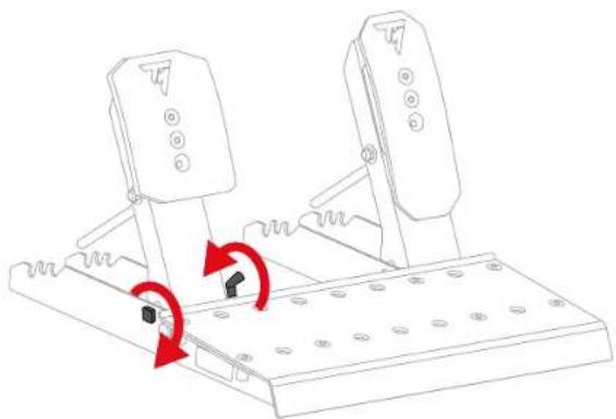
Mechanical assembly diagram showing two rotating components with red arrows indicating motion or force direction (no text or symbols)- Tighten the stop rod, without forcing it.
Repeat the procedure on the other pedal.
natural_image
Technical line drawing of a mechanical lever mechanism with red arrows indicating rotational motion (no text or symbols)
Do not overtighten the stop rod.
Brake pedal:
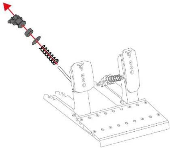
The parts that make up the brake pedal's spring are in a bag. There are two springs with different resistances:
- A1 spring (long, black): weak resistance;
- A2 spring (short, grey): strong resistance.
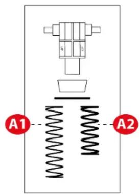

Set aside the spring that you do not want to use.
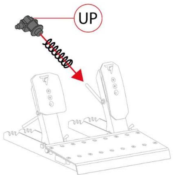
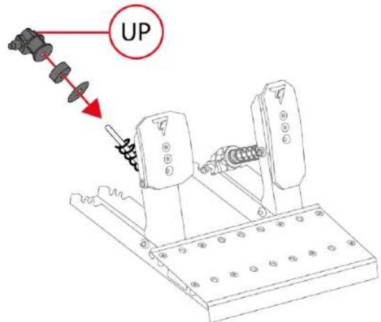
- Insert all the parts of the brake pedal spring on the metal rod in the following order: spring, washer, buffer and support.
On the support, the UP marking must point upwards.
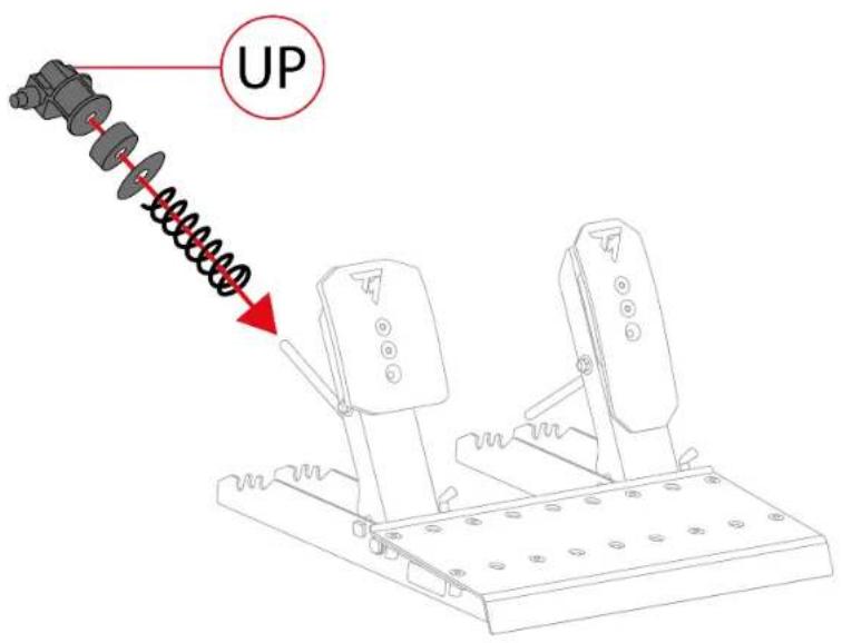
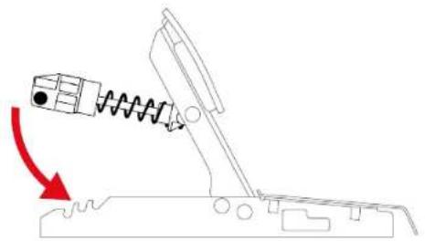
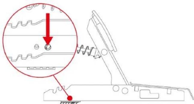
- Compress the brake pedal spring using the support, to insert the retaining rod into the slots in the pedal set base.
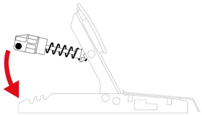
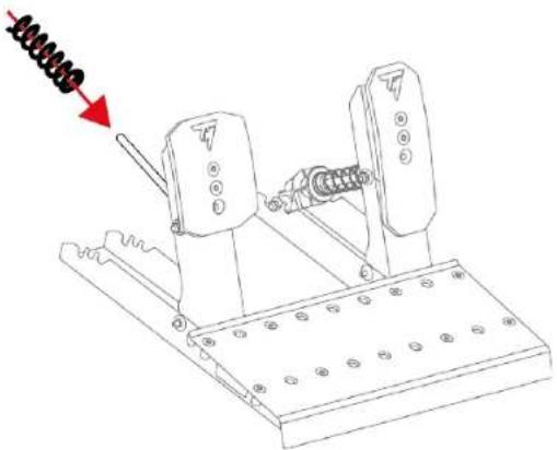
natural_image
Diagram of a mechanical device with a spring and block, showing motion direction (no text or symbols)To adjust the brake pedal's resistance, you can place the spring retaining rod in different positions.

For more information on adjusting the brake pedal's resistance, please read the Pedal set mechanical settings section.
Accelerator pedal:
The parts that make up the accelerator pedal's spring are in a bag. The bag contains a single B1 spring (very long, grey).
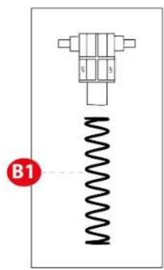
- Insert all the parts of the accelerator pedal spring on the metal rod in the following order: spring and support.
On the support, the UP marking must point upwards.
- Compress the accelerator pedal spring using the support, to insert the retaining rod into the slots in the pedal set base.
natural_image
Diagram of a mechanical device with a spring and arrow indicating motion (no text or symbols)To adjust the accelerator pedal's resistance, you can place the spring retaining rod in different positions.

For more information on adjusting the accelerator pedal's resistance, please read the Pedal set mechanical settings section.

A video showing assembly of the pedal set is available here:
https://support.thrustmaster.com/product/raceline-pedals-lte/
5. Installation
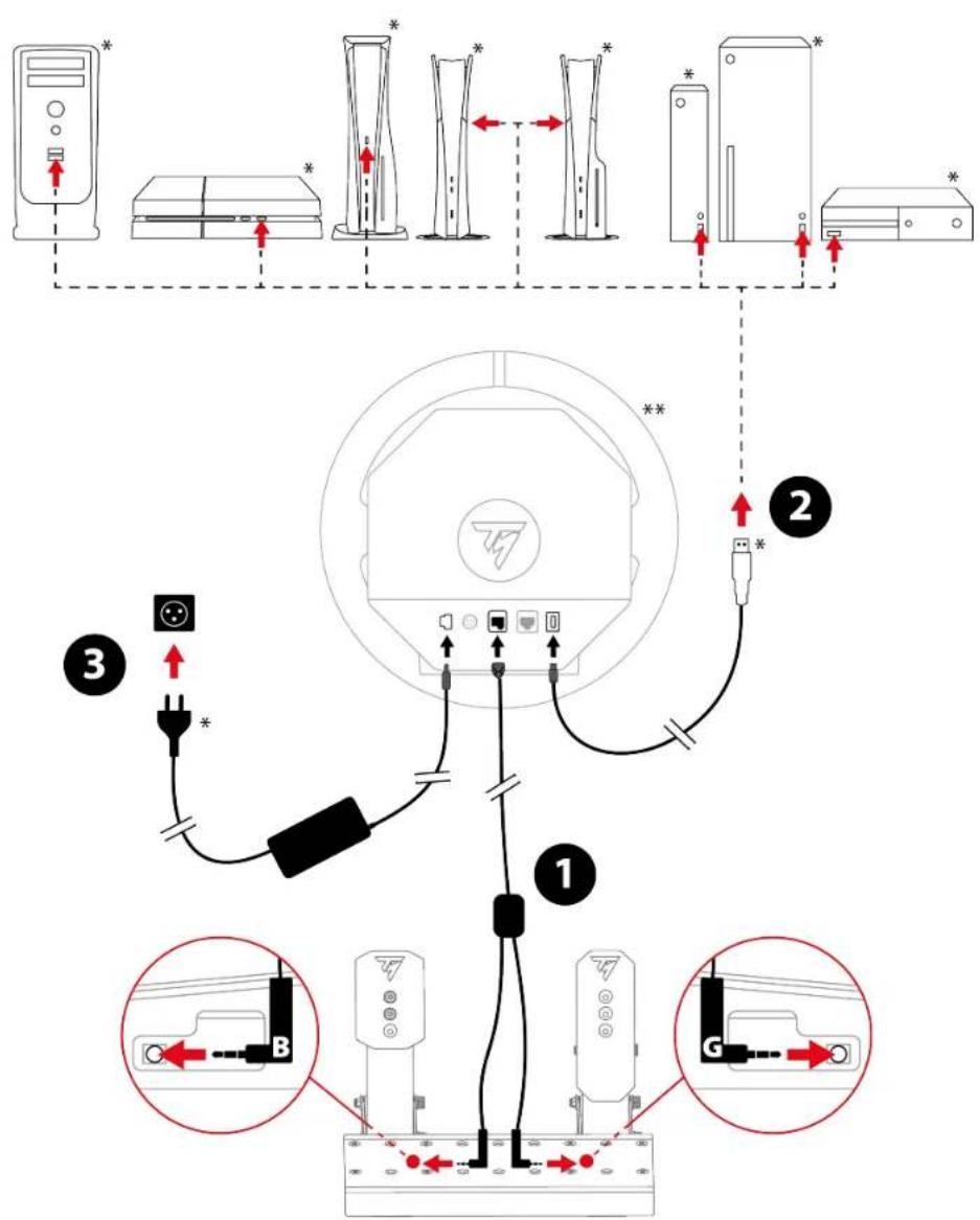
*Not included
**Racing wheel base not included

The installation procedure may vary slightly, depending on the racing wheel base being used. For more information, please refer to the racing wheel base's user manual.
- Connect the double jack/RJ12 cable to the RJ12 connector on the base and the Raceline Pedals LTE pedal set.

The jack connector with the B marking (Brake) connects to the brake pedal. The jack connector with the G marking (Gas) connects to the accelerator pedal.
- Connect the base to a USB-A port on the game console or PC.
- Connect the power adapter to the base, and also plug it into a wall outlet.
You are now ready to play!
Compatibility
The Raceline Pedals LTE pedal set is compatible with Thrustmaster Force Feedback racing wheel bases.
6. Pedal set mechanical settings
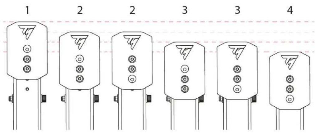
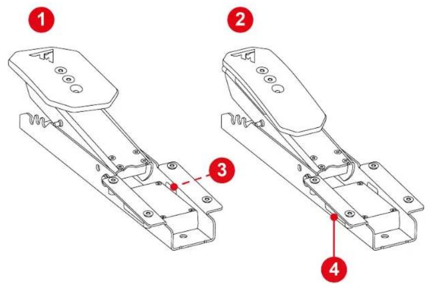
Adjusting the height of the pedals
The height of the brake pedal and accelerator pedal can be adjusted. There are four possible positions for each pedal.
Brake pedal:
Accelerator pedal:
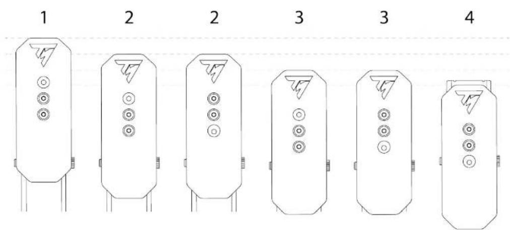
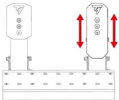
- Use the included T20 Torx wrench to unscrew the two screws holding the pedal head in place.
- Select the new pedal head position.
natural_image
Technical diagram showing two identical electrical or mechanical components mounted on a base, with red double-headed arrows indicating vertical displacement (no text or symbols present)- Reinsert and retighten the two screws holding the pedal head in place.
Modifying the brake pedal's resistance
Two springs are included for adjusting the brake pedal's resistance:
- A1 spring (long, black): weak resistance;
- A2 spring (short, grey): strong resistance.
The three slots at the back of the pedal set base are used to adjust the resistance setting.
A1 spring
| Position | P1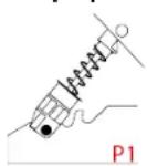 | P2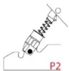 | P3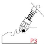 |
| Resistance |  | 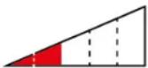 |  |
A2 spring
| Position | P1 | P2 | P3 |
| - |  |  | |
| Resistance | - |  |  |

The A2 spring cannot be used in the P1 position.
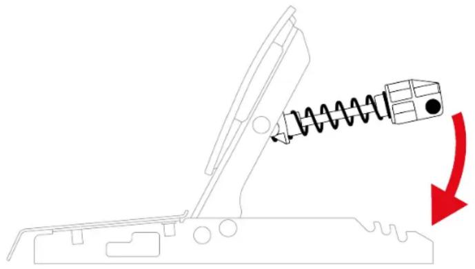
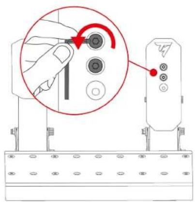
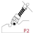
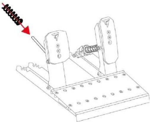
- To release the spring retaining rod from the slots, compress the spring using the support.
natural_image
Diagram of a mechanical lever system with spring and rotating arrow (no text or symbols)- Remove all of the pedal spring's parts.
natural_image
Mechanical assembly diagram showing a spring-loaded mechanism with no visible text or symbols- Insert the new spring onto the pedal's metal rod.
natural_image
Technical line drawing of a mechanical device with spring-loaded lever and base plate (no text or symbols)- Insert the other parts of the brake pedal spring onto the metal rod in the following order: washer, buffer and support.
On the support, the UP marking must point upwards.
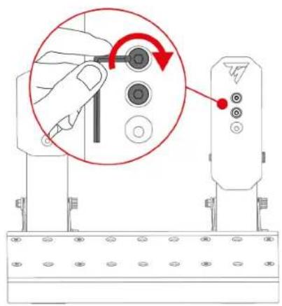
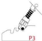
- To insert the spring retaining rod into the slots (P1, P2 or P3), compress the spring using the support.
natural_image
Mechanical diagram showing a spring-loaded lever mechanism with a red arrow indicating motion direction (no text or symbols)
To prevent any calibration problems, we recommend that you restart the base after changing the spring.
Modifying the accelerator pedal's resistance
Only one spring is included for the accelerator pedal (B1 spring: very long, grey, weak resistance).
The three slots at the back of the pedal set base are used to adjust the resistance setting.
| B1 spring | |||
| Position | P1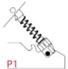 | P2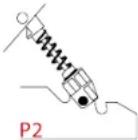 | P3 |
| Resistance | 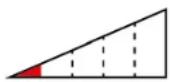 | 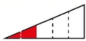 | 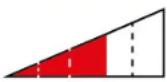 |
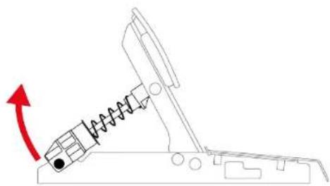
- To release the spring retaining rod from the slots, compress the spring using the support.
natural_image
Diagram of a mechanical device with a spring-loaded component and red arrow indicating motion (no text or symbols)- To insert the spring retaining rod into the slots (P1, P2 or P3), compress the spring using the support.
natural_image
Diagram of a mechanical device with spring and connecting rod, showing motion direction (no text or symbols)
To prevent any calibration problems, we recommend that you restart the base after changing the spring.
7. Carpet Grip non-slip supports
The Carpet Grip non-slip supports prevent the Raceline Pedals LTE pedal set from moving when used on a carpet or rug.
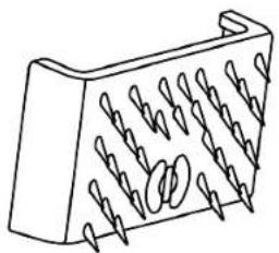
natural_image
Line drawing of a 3D mechanical component with multiple spiral grooves (no text or symbols)
Do not use the Carpet Grip non-slip supports on a soft floor or parquet flooring, as this may damage the floor covering (e.g., scuffs, scratches).
Assembly
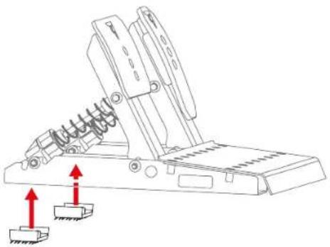
To install the Carpet Grip non-slip supports, clip them to the back of the pedal set.
natural_image
Technical line drawing of a mechanical device with spring and base components, showing upward red arrows indicating motion (no text or symbols)
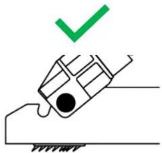
To ensure that the supports are effective, position the teeth towards the back of the pedal set.
natural_image
Simple line drawing of a hand holding a tool with a green checkmark above it (no text or symbols)
Disassembly
To remove the Carpet Grip non-slip supports:
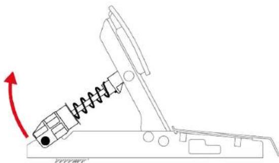
- Release the springs from the notches.
natural_image
Diagram of a mechanical device with a spring and rotating arm, showing motion direction (no text or symbols)- Press the clip of each non-slip support.

Do not pull on the sides of the Carpet Grip non-slip supports to remove them. You risk breaking the supports.
8. FAQ and technical support
Do you have questions regarding the Raceline Pedals LTE pedal set, or are you experiencing technical problems? If so, visit the Thrustmaster technical support website:
https://support.thrustmaster.com/product/raceline-pedals-lte/

THRUSTMASTER®
RACELINE PEDALS LTE
LONG TERM EVOLUTION
PC (Windows 10/11)
PS4® / PS5®
Xbox Series / Xbox One
natural_image
Technical line drawing of two mechanical device components with mounting holes and spring-like brackets (no text or symbols)
natural_image
Line drawing of a rectangular metal plate with evenly spaced circular holes (no text or symbols)
natural_image
Pure mechanical assembly diagram showing a valve, spring, and housing (no text or symbols)
natural_image
Pure mechanical component diagram without any text, numbers, or symbols
natural_image
Simple electrical circuit diagram with a bulb, capacitor, and two labeled components (G and B) without any text or symbols.
natural_image
Isometric view of a 3D rectangular block with spiral grooves and a side label 'x 2' (no text or symbols on the object itself)

2. Caractéristiques

natural_image
Line drawing of a rectangular metal plate with evenly spaced circular holes, labeled with number 5 (no text or symbols on the plate itself)4. Montage

Risque de pincement
natural_image
Technical line drawing of a mechanical support structure with mounting holes and red dashed lines indicating assembly points (no text or symbols present)natural_image
Mechanical assembly diagram showing two rotating components with red arrows indicating motion or force direction (no text or symbols)natural_image
Technical line drawing of a mechanical lever mechanism with red arrows indicating rotational motion (no text or symbols)
natural_image
Diagram of a mechanical device with spring and block components, showing motion direction (no text or symbols)natural_image
Diagram of a mechanical device with a spring and arrow indicating motion (no text or symbols)*Non fourni
**Base non fournie.

natural_image
Technical diagram showing two identical electrical or mechanical components mounted on a base, with red double-headed arrows indicating vertical displacement (no text or symbols present)natural_image
Diagram of a mechanical lever system with spring and rotating component (no text or symbols)natural_image
Technical line drawing of a mechanical device with spring-loaded components and mounting base (no text or symbols)natural_image
Technical line drawing of a mechanical device with spring and base plate (no text or symbols)natural_image
Diagram of a mechanical device with spring and lever mechanism, showing motion direction (no text or symbols)
natural_image
Diagram of a mechanical device with a spring and directional arrow (no text or symbols)natural_image
Diagram of a mechanical device with spring and damper, showing motion direction (no text or symbols)
natural_image
Line drawing of a 3D rectangular object with spiral grooves and a looped edge (no text or symbols)
natural_image
Technical line drawing of a mechanical lever mechanism with two red arrows indicating upward motion (no text or symbols present)
natural_image
Simple line drawing of a hand holding a device with a green checkmark above it (no text or symbols)
Démontage
natural_image
Diagram of a mechanical device with a spring and rotating arm, showing motion direction (no text or symbols)
https://support.thrustmaster.com/product/raceline-pedals-lte/

THRUSTMASTER®
RACELINE PEDALS LTE
LONG TERM EVOLUTION
PC (Windows 10/11)
PS4® / PS5®
Xbox Series / Xbox One
Benutzerhandbuch

natural_image
Technical line drawing of two mechanical device components with mounting holes and spring-like brackets (no text or symbols)
natural_image
Line drawing of a metal plate with evenly spaced circular holes (no text or symbols)
natural_image
Pure mechanical assembly diagram without any text, numbers, or symbols
natural_image
Pure mechanical component diagram without any text, numbers, or symbols

natural_image
Simple electrical circuit diagram with a bulb, capacitor, and two labeled components (G and B) without any text or symbols.

natural_image
Isometric view of a 3D rectangular block with spiral grooves and a side label 'x 2' (no text or symbols on the object itself)
2. Funktionen


natural_image
Line drawing of a rectangular plate with evenly spaced circular holes, labeled with number 5 (no text or symbols on the plate itself)4. Zusammenbau

Einklemmgefahr
natural_image
Technical line drawing of a mechanical assembly with mounting brackets and red bolted fasteners (no text or symbols)natural_image
Mechanical assembly diagram showing two lever mechanisms with red arrows indicating motion or force direction (no text or symbols)natural_image
Technical line drawing of a mechanical lever mechanism with red arrows indicating motion (no text or symbols)
natural_image
Diagram of a mechanical device with spring and block components, showing motion direction (no text or symbols)natural_image
Diagram of a mechanical device with a spring and arrow indicating motion (no text or symbols)https://support.thrustmaster.com/product/raceline-pedals-lte/
5. Installation

natural_image
Technical diagram of two vertical-mounted electrical connectors with mounting holes and red double-headed arrows indicating vertical displacement (no text or symbols)natural_image
Diagram of a mechanical lever system with spring and rotating arrow (no text or symbols)natural_image
Technical line drawing of a mechanical device with spring-loaded components and mounting base (no text or symbols)natural_image
Technical line drawing of a mechanical device with spring-loaded components and mounting base (no text or symbols)natural_image
Diagram of a mechanical device with spring and chain, showing motion direction (no text or symbols)
natural_image
Diagram of a mechanical device with spring and rotational arrow (no text or symbols)natural_image
Diagram of a mechanical device with spring and damper, showing motion direction (no text or symbols)
natural_image
Isometric line drawing of a 3D rectangular block with multiple spiral grooves (no text or symbols)
natural_image
Technical line drawing of a mechanical device with spring and base components, showing two red arrows indicating motion direction (no text or symbols)
natural_image
Simple line drawing of a hand holding a car with a green checkmark above it (no text or symbols)
Demontage
natural_image
Mechanical diagram showing a spring-loaded lever system with a red arrow indicating rotational motion (no text or symbols)
https://support.thrustmaster.com/product/raceline-pedals-lte/

THRUSTMASTER®
RACELINE PEDALS LTE
LONG TERM EVOLUTION
PC (Windows 10/11)
PS4® / PS5®
Xbox Series / Xbox One
Handleiding

natural_image
Technical line drawing of two mechanical device components with mounting holes and spring-like brackets (no text or symbols)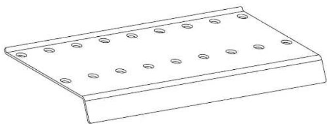
natural_image
Line drawing of a rectangular metal plate with evenly spaced circular holes (no text or symbols)
natural_image
Pure mechanical assembly diagram showing a valve, spring, and housing (no text or symbols)
natural_image
Pure mechanical component diagram without any text, numbers, or symbols

natural_image
Simple electrical circuit diagram with a bulb, capacitor, and two labeled terminals (G and B) connected by wires (no text or symbols beyond labels)

natural_image
3D diagram of a mechanical component with multiple grooves and a central hole, labeled 'x 2' (no text or symbols on the object itself)

2. Functies


natural_image
Line drawing of a rectangular plate with evenly spaced circular holes, labeled with number 5 (no text or symbols on the plate itself)4. Montage

natural_image
Technical line drawing of a mechanical assembly with mounting brackets and red dashed lines indicating alignment or assembly points (no text or symbols present)natural_image
Mechanical assembly diagram showing two monitors with red arrows indicating motion or force direction (no text or symbols)natural_image
Technical line drawing of a mechanical lever mechanism with red arrows indicating motion (no text or symbols)
natural_image
Diagram of a mechanical device with spring and block components, showing motion direction (no text or symbols)natural_image
Diagram of a mechanical device with a spring and arrow indicating motion (no text or symbols)https://support.thrustmaster.com/product/raceline-pedals-lte/
5. Installatie

*Niet meegeleverd
natural_image
Technical line drawing of two vertical-mounted device components with mounting brackets and red double-headed arrows indicating vertical displacement (no text or symbols)natural_image
Diagram of a mechanical lever system with spring and rotating component (no text or symbols)natural_image
Technical line drawing of a mechanical assembly with spring-loaded components and mounting base (no text or symbols)natural_image
Technical line drawing of a mechanical device with spring and mounting base (no text or symbols)natural_image
Diagram of a mechanical device with spring and lever mechanism, showing motion direction (no text or symbols)
natural_image
Diagram of a mechanical device with a spring and directional arrow (no text or symbols)natural_image
Diagram of a mechanical device with spring and damper, showing motion direction (no text or symbols)
natural_image
Line drawing of a 3D object with spiral grooves and a looped edge (no text or symbols)
natural_image
Mechanical lever diagram with spring and base blocks, no text or symbols present
natural_image
Simple line drawing of a hand holding a tool with a green checkmark above it (no text or symbols)
Demontage
natural_image
Diagram of a mechanical device with a spring and rotating arrow, no text or symbols present
https://support.thrustmaster.com/product/raceline-pedals-lte/

THRUSTMASTER®
RACELINE PEDALS LTE
LONG TERM EVOLUTION
PC (Windows 10/11)
PS4® / PS5®
Xbox Series / Xbox One
Manuale d'uso

natural_image
Technical line drawing of two mechanical device components with mounting holes and spring-like brackets (no text or symbols)
natural_image
Line drawing of a rectangular metal plate with evenly spaced circular holes (no text or symbols)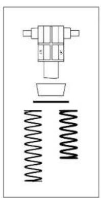
natural_image
Pure mechanical assembly diagram showing a valve, spring, and housing (no text or symbols)
natural_image
Pure mechanical component diagram without any text, numbers, or symbols

natural_image
Simple electrical circuit diagram with battery, switch, and two labeled terminals (G and B) without any text or symbols
natural_image
3D diagram of a mechanical component with multiple grooves and a central hole, labeled 'x 2' (no text or symbols on the object itself)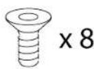

2. Caratteristiche

natural_image
Line drawing of a rectangular plate with evenly spaced circular holes, labeled with number 5 (no text or symbols on the plate itself)4. Assemblaggio

natural_image
Technical line drawing of a mechanical support structure with mounting brackets and red dashed lines indicating assembly points (no text or symbols present)natural_image
Mechanical assembly diagram showing two rotating components with red arrows indicating motion, no text or symbols presentnatural_image
Technical line drawing of a mechanical lever mechanism with red arrows indicating rotational motion (no text or symbols)
natural_image
Diagram of a mechanical device with spring and block components, showing motion direction (no text or symbols)natural_image
Diagram of a mechanical device with a spring and arrow indicating motion (no text or symbols)https://support.thrustmaster.com/product/raceline-pedals-lte/
5. Installazione

*Non inclusi
natural_image
Technical diagram showing two identical electrical or mechanical components mounted on a base, with red double-headed arrows indicating vertical displacement (no text or symbols present)natural_image
Diagram of a mechanical lever system with spring and rotating arrow (no text or symbols)natural_image
Mechanical assembly diagram showing a spring-loaded mechanism with no visible text or symbolsnatural_image
Technical line drawing of a mechanical device with spring-loaded components and mounting base (no text or symbols)natural_image
Diagram of a mechanical device with a spring and rotating component, showing motion direction (no text or symbols)
natural_image
Diagram of a mechanical device with a spring and directional arrow (no text or symbols)natural_image
Diagram of a mechanical device with spring and damper, showing motion direction (no text or symbols)
natural_image
Isometric line drawing of a 3D rectangular block with spiral grooves and a circular hole at the center (no text or symbols)
natural_image
Technical line drawing of a mechanical lever mechanism with red arrows indicating upward motion (no text or symbols)
natural_image
Simple line drawing of a hand pressing a car with a green checkmark above (no text or symbols)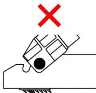
natural_image
Simple line drawing of a hand holding a tool with a red X mark above, no text or symbols present.Smontaggio
natural_image
Diagram of a mechanical device with a spring and rotating arrow, no text or symbols present
https://support.thrustmaster.com/product/raceline-pedals-lte/

THRUSTMASTER®
RACELINE PEDALS LTE
LONG TERM EVOLUTION
PC (Windows 10/11)
PS4® / PS5®
Xbox Series / Xbox One
Manual del usuario

natural_image
Technical line drawing of two mechanical device components with mounting holes and spring supports (no text or symbols)
natural_image
Line drawing of a metal plate with evenly spaced circular holes (no text or symbols)
natural_image
Pure mechanical assembly diagram without any text, numbers, or symbols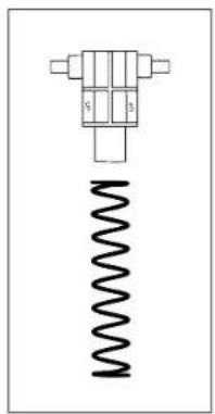
natural_image
Pure mechanical component diagram without any text, numbers, or symbols

natural_image
Simple electrical circuit diagram with battery, switch, and two labeled terminals (G and B) without any text or symbols

natural_image
3D diagram of a mechanical component with multiple grooves and a cross-shaped base, labeled 'x 2' (no text or symbols on the component itself)

2. Características

natural_image
Line drawing of a rectangular metal plate with evenly spaced circular holes, labeled with number 5 (no text or symbols on the plate itself)4. Montaje

Peligro de pillarse
natural_image
Technical line drawing of a mechanical support structure with mounting brackets and red dashed lines indicating assembly points (no text or symbols present)natural_image
Mechanical assembly diagram showing two rotating components with red arrows indicating motion, no text or symbols presentnatural_image
Technical line drawing of a mechanical lever mechanism with red arrows indicating rotational motion (no text or symbols)
natural_image
Diagram of a mechanical device with a spring and block, showing motion direction (no text or symbols)natural_image
Diagram of a mechanical device with a spring and arrow indicating motion (no text or symbols)https://support.thrustmaster.com/product/raceline-pedals-lte/
5. Instalación
*No incluidos
natural_image
Technical diagram showing two vertical-mounted devices mounted on a base with red double-headed arrows indicating vertical displacement (no text or symbols present)natural_image
Diagram of a mechanical lever system with spring and rotating component (no text or symbols)natural_image
Technical line drawing of a mechanical assembly with spring-loaded components and mounting base (no text or symbols)natural_image
Technical line drawing of a mechanical device with spring-loaded components and mounting base (no text or symbols)natural_image
Diagram of a mechanical device with spring and lever mechanism, showing motion direction (no text or symbols)
natural_image
Diagram of a mechanical device with a spring and directional arrow (no text or symbols)natural_image
Diagram of a mechanical device with spring and damper, showing motion direction (no text or symbols)
natural_image
Isometric line drawing of a 3D rectangular block with spiral grooves and a circular hole, no text or symbols present.
natural_image
Technical line drawing of a mechanical lever mechanism with two red arrows indicating upward motion (no text or symbols present)
natural_image
Simple line drawing of a hand holding a tool with a green checkmark above it (no text or symbols)
Desmontaje
natural_image
Diagram of a mechanical device with a spring and rotating arrow, no text or symbols present
https://support.thrustmaster.com/product/racelinepedals-lte/

THRUSTMASTER®
RACELINE PEDALS LTE
LONG TERM EVOLUTION
PC (Windows 10/11)
PS4® / PS5®
Xbox Series / Xbox One
Manual do Utilizador

natural_image
Technical line drawing of two mechanical device components with mounting holes and spring-like brackets (no text or symbols)
natural_image
Line drawing of a rectangular metal plate with evenly spaced circular holes (no text or symbols)
natural_image
Pure mechanical assembly diagram showing a valve, spring, and housing (no text or symbols)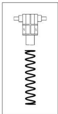
natural_image
Pure mechanical component diagram without any text, numbers, or symbols

natural_image
Simple electrical circuit diagram with battery, switch, and two labeled terminals (G and B) without any text or symbols

natural_image
Isometric view of a 3D rectangular block with spiral grooves and a label 'x 2' (no text or symbols on the object itself)

2. Características


natural_image
Line drawing of a rectangular plate with evenly spaced circular holes, labeled with number 5 (no text or symbols on the plate itself)4. Montagem

Perigo de entalamento
natural_image
Technical line drawing of a mechanical support structure with mounting holes and red dashed lines indicating assembly points (no text or symbols present)natural_image
Mechanical assembly diagram showing two rotating components with red arrows indicating motion or force direction (no text or symbols)natural_image
Technical line drawing of a mechanical lever mechanism with red arrows indicating rotational motion (no text or symbols)
natural_image
Diagram of a mechanical device with spring and block components, showing motion direction (no text or symbols)natural_image
Diagram of a mechanical device with a spring and arrow indicating motion (no text or symbols)https://support.thrustmaster.com/product/raceline-pedals-lte/
5. Instalação

* Não incluído
natural_image
Technical diagram showing two vertical-mounted device components with mounting brackets and red double-headed arrows indicating vertical displacement (no text or symbols)natural_image
Diagram of a mechanical lever system with spring and rotating component (no text or symbols)natural_image
Technical line drawing of a mechanical assembly with spring-loaded components and mounting base (no text or symbols)- Insira a nova mola na haste de metal do pedal.
natural_image
Technical line drawing of a mechanical device with spring and mounting base (no text or symbols)natural_image
Diagram of a mechanical device with spring and damper, showing motion direction (no text or symbols)
natural_image
Diagram of a mechanical device with a spring and directional arrow (no text or symbols)natural_image
Diagram of a mechanical device with spring and damper, showing motion direction (no text or symbols)
natural_image
Line drawing of a 3D rectangular object with spiral grooves and a looped edge (no text or symbols)
natural_image
Technical line drawing of a mechanical lever mechanism with red arrows indicating upward motion (no text or symbols)
natural_image
Simple line drawing of a hand holding a car with a green checkmark above it (no text or symbols)
Desmontagem
Para remover os suportes antiderrapantes Carpet Grip:
- Solte as molas dos entalhes.

natural_image
Diagram of a mechanical device with a spring and rotating arrow, no text or symbols present
https://support.thrustmaster.com/product/raceline-pedals-lte/


- TABLE OF CONTENTS
- RACELINE PEDALS LTE
- Box contents
- Features
- Information regarding use
- Documentation
- Electrical shock
- Injuries due to repeated movements
- Pedal set pinch hazard when playing
- Assembly
- Brake pedal:
- Accelerator pedal:
- Installation
- Compatibility
- Pedal set mechanical settings
- Adjusting the height of the pedals
- Modifying the brake pedal's resistance
- Modifying the accelerator pedal's resistance
- Carpet Grip non-slip supports
- Assembly
- Disassembly
- FAQ and technical support
- THRUSTMASTER®
- Caractéristiques
- Montage
- Risque de pincement
- Démontage
- Funktionen
- Zusammenbau
- Einklemmgefahr
- Demontage
- Functies
- Installatie
- Caratteristiche
- Assemblaggio
- Installazione
- Smontaggio
- Manual del usuario
- Características
- Montaje
- Peligro de pillarse
- Instalación
- Desmontaje
- Montagem
- Perigo de entalamento
- Instalação
- Desmontagem
Brand : THRUSTMASTER
Model : Raceline Pedals LTE
Category : Controller