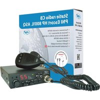
Escort HP 8000L - Talkie Walkie PNI - Free user manual and instructions
Find the device manual for free Escort HP 8000L PNI in PDF.


User questions about Escort HP 8000L PNI
0 question about this device. Answer the ones you know or ask your own.
Ask a new question about this device
Download the instructions for your Talkie Walkie in PDF format for free! Find your manual Escort HP 8000L - PNI and take your electronic device back in hand. On this page are published all the documents necessary for the use of your device. Escort HP 8000L by PNI.
USER MANUAL Escort HP 8000L PNI
natural_image
Black PN Radio remote control device with attached coiled cable and digital display (no visible text or symbols on main body)EN User manual 3
⚠️ Please read the following precautions to prevent fire, personal injury or the product's destruction.
Do not attempt to set the radio while driving; it might be dangerous.
This product is designed for 12V DC. Do not use a 24V battery to power the radio.
Do not place the radio on an excessively dusty, damp or unstable surface.
Do not connect the antenna during transmission, risk electric shock.
⚠️ Please keep the distance from devices that cause interference (such as TV, generator, etc.)
⚠️ People who use pacemakers are advised to keep distance from the antenna during transmission and especially not to touch it.
Do not approach metal objects to the internal electrical side pf the radio; danger of electric shock.
Avoid exposing the radio to temperatures below -26^ and above +60^ . The temperature inside a vehicle may sometimes exceed +80^ , which can cause irreparable damages to electric devices. Do not expose the radio to direct sunlight.
Do not place anything on the radio, it will prevent it from cooling down.
Check if you have the vehicles battery charged enough to avoid its quick discharge.
⚠️ It is important to turn the radio off before starting the engine, to avoid damages caused by high starting voltage.
You must use a 2A 250V type F fuse. No not use a fuse with higher value.
⚠️ If an abnormal smell or smoke is detected as coming from the radio, switch off the appliance immediately.
Do not transmit for a long time, the radio may warm up.
⚠️ Keep the radio away from children.
OTHER WARNINGS:
Before connecting or using this product, please read these operating instructions carefully. Keep this manual for future reference.
Before using the radio, please connect the antenna, then check the SWR before transmitting. A too high value of SWR can cause demages to the CB output transistors, which are not covered by the warranty.
The radio does not include components that can be repaired by the user. Please contact an authorized service center.
To prevent the risk of fire, use only a suitable power supply.
MAIN CARACTERISTICS:
• 40 FM/AM channels
• FM/AM mode selection switch (AM only works by changing the standard)
• Emergency channel selection switch
- Key lock switch
- UP/DOWN Channel selection buttons
- Signal level LED
• 2-digit channel number indicator
• Volume potentiometer
• LED indicators for RX/TX/ASQ
- Microphone with channel selection buttons (up/down) and ASQ activation
- 6-pin microphone jack on the front panel
- External speaker jack
- Manual squelch and adjustable ASQ
TECHNICAL SPECIFICATIONS:
| Channels 40 AM/FM | |
| Frequency band 26.965 – 27.405 MHz | |
| Frequency control P.L.L. | |
| Operating temperature -26° - +60°C | |
| Power supply 12Vdc ±15% | |
| Dimensions/weight 115 x 36 x 152 mm/0.8 kg | |
| Receiver | |
| Intermediate frequency 1° 10.7 MHz/2° 450 KHz | |
| Sensitivity | -120dBm/12dB SINAD (FM) |
| -107dBm/12dB SINAD (AM) | |
| Audio output @10% THD 2.5W la 8 ohm | |
| Audio distortion <8% at 1 KHz | |
| Image rejection 65 dB | |
| Adjacent channel 85 dB | |
| Current consumption 200 mA in stand-by | |
| Transmitter | |
| Maximum RF power | 4W FM at 12Vdc |
| Modulation | 85% ~ 90% (AM) |
| 3KHz ±0.2 KHz (FM) | |
| Antenna impedance | 50 Ohm |
| Current consumption 2 A |
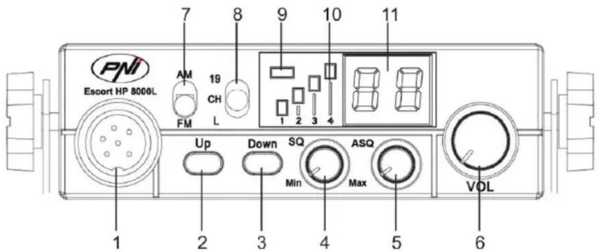
FRONT PANEL DESCRIPTION:
text_image
PNI Escort HP 8000L 7 8 9 10 11 AM 19 CH FM L 1 2 3 4 Up Down SQ Min ASQ Max VOL 1 2 3 4 5 6- 6-pin microphone connector
- Increase channel number
- Decrease channel number
- Knob for squelch adjustment – the squelch makes your radio quieter by removing the background noise. Rotate the knob clockwise to reduce the noise or counterclockwise if you want to hear even the weakest signals.
- ASQ knob – to increase the ASQ level rotate the knob clockwise. In this case it reduces the background noise but also the signal level received.
Tip: turn on the radio with the ASQ knob turned completely to the left.
- Knob for turning on/off the radio and for volume control – Turn clockwise to turn the radio on and to increase the volume. If no signal is received, we suggest you to adjust the squelch (by rotating the SQ knob counterclockwise) and then adjust the volume to a comfortable level. When switched on from the volume knob, the radio will store the last channel used.
- AM/FM mode select button
Note: The radio works in AM mode only by changing the standard (details on page 7)
- Multifunctional switch:
• "19": emergency channel selection
- “CH”: channel selection 1\~40 (according to the selected standard)
- “L”: key lock
- TX/ASQ LED indicator - During the transmission the LED will be red, and when the ASQ function is activated, the LED will be green.
- Signal level indicator - 4-bar indicator to monitor the power of the received/emitted signals
- LED display – displays the channel number
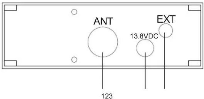
REAR PANEL DESCRIPTION:
- Antenna jack
- 12VDC power cable
- External speaker jack
text_image
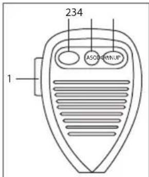
ANT 13.8VDC EXT 123MICROPHONE DESCRIPTION:
text_image
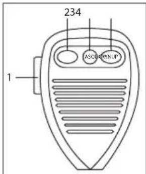
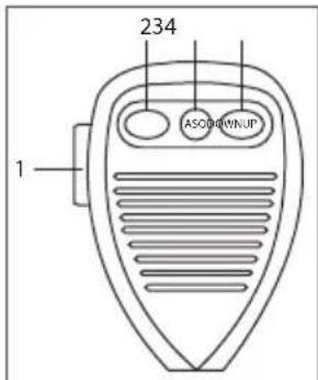
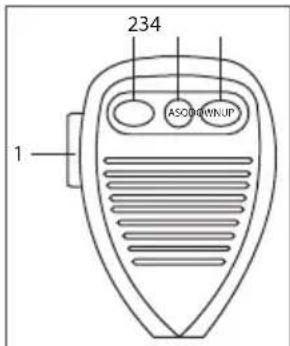
234 ASO#DOWNUP 1- PTT button – Push to Talk
- Increase channel number
- Enable/disable ASQ function
- Decrease channel number
INSTALLATION INSTRUCTIONS:
natural_image
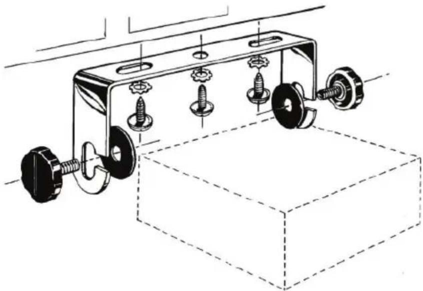
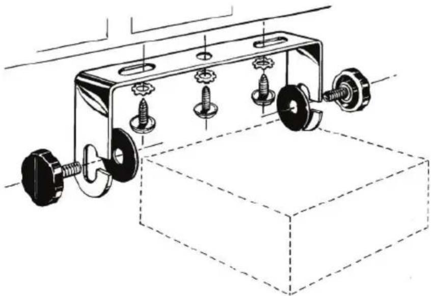
Technical line drawing of a mechanical assembly with screws and nuts, no text or symbols presentBefore installing the radio in your vehicle, choose the most suitable location so you can use it without being disturbed while driving.
To install the radio, use the mounting bracket and the accessories in the package. The screws must be securely clamped to avoid vibration of the radio while driving. The mounting bracket can be positioned above or below the device and can be tilted depending on the installation mode (under the dashboard or under the ceiling).
WARNING: Power the radio to 12V only.
Installation of the central unit:
Before powering the radio, make sure that the power knob is fully turned to the left.
The power cord of the radio includes a protective fuse on the red wire. Connect the radio's power cable to the car's electrical system paying attention to the polarity (even if the radio has protection against polarity reversal).
Connect the red wire to the positive terminal (+) and the black wire at the negative terminal (-) of the vehicle's electrical system. Check the connections were made correctly to prevent them from being disconnected or possibly short-circuiting.
WARNING: Do not replace the fuse with one with a higher value. The fuse from the actory has 2A.
Antenna installation:
To use this radio, you need an antenna that operates at 26-28MHz.
To install the antenna, call a specialist.
Before connecting the antenna to the radio, it is necessary to check it with a specialized device to prevent the transmission circuit failure.
Typically, the antenna should be positioned on the highest side of the vehicle without being obstructed by
obstacles and as far from any electrical source or electromagnetic noise. The coaxial cable of the antenna should not be interrupted or pressed. Connect the plug at the end of the coaxial antenna cable to the antenna jack on the rear panel of the radio.
Check the radio:
Once installed and powered from the vehicle's electrical system, do the following to verify its operation:
- Check that the radio is powered correctly
- Check the antenna connection to the radio
- Connect the microphone to the jack on the front panel of the radio
• Turn on the radio by rotating the volume knob clockwise and adjust the volume to the desired level - Select the desired channel with the UP/DOWN keys on the front panel or on the microphone.
- Press the SQ button in the limit area where the background noise disappears.
Note: If the ASQ mode is enabled (by pressing the ASQ on the microphone) the SQ button can not be activated
- Press the PTT button on the microphone to emit, and release it to receive
- Check the signal level received via the signal bars on the front panel
- Turn the ASQ function on the microphone and adjust its level from the ASQ button on the front panel of the station
USEFUL TIPS:
Do not reverse the polarity when powering the radio.
Do not replace the fuse with a higher value. The fone from the factory has 2A.
Do not emit without an antenna or a broken or not tuned antenna to avoid burning the CB output transistors. Adjust the SQ and ASQ until the background noise disappears. By turning the SQ knob clockwise too much, you will receive only the strong signals (those emitted nearby).
CHANGING THE STANDARD:
To change the standard of the radio, do as follows:
- Turn off the radio
- While holding down the Down and PTT buttons on the microphone, turn the radio on
- Use the up and down keys on the radio to select the desired standard
- Turn the radio off and back on
To check the current norm do the same procedure.
Available norms:
| Norm Frequency (MHZ) Channels Country EMG (19) | ||||
| EU 26.965 | -27.405 40CH (4W) AM/FM EU | CH09: 27.065MHz AM/FMCH19: 27.185MHz AM/FM | ||
| CE 26.965 | -27.405 40CH (4W) FM only RO, MT CH19: 27.185MHz FM | |||
| -9 | 26.965-27.405 01CH-40CH (4W) AM/FM | DE CH19: 27.185 AM/FM | ||
| 26.565-26.955 41CH-80CH (4W) FM only | ||||
| -U* | 27.60125-27.99125 | 40CH (4W) FM only | UK | CH19: 27.78125MHz FM |
| -P | 26.960-27.400 | -5KHZ 40CH (4W) AM/FM | PL | CH19: 27.180MHz AM/FM |
| -d | 26.965-27.405 | 40CH (4W) AM/FM | DE | CH19: 27.185MHz AM/FM |
*In -U configuration, in order to select the frequency band CE, move the AM/FM switch to AM position. CE shortly appears on the display. Move back to FM position, you are back in -U norm. -U shortly shortly appears on the display.
ПРЕДУПРЕЖДЕНИЯ ЗА БЕЗОПАСНОСТ
text_image
ANT 13.8VDC EXTОПИСАНИЕ МИКРОФОН:
text_image
234 ASO#DOWNUP 1natural_image
Technical line drawing of a mechanical assembly with bolts and a base (no text or symbols)text_image
ANT 13.8VDC EXT 15 123natural_image
Technical line drawing of a mechanical assembly with gears and a base block (no text or symbols)text_image
ANT 13.8VDC EXT 123DESCRIPTION MICRÓFONO:
natural_image
Technical line drawing of a mechanical assembly with gears and a base block (no text or symbols)text_image
ANT 13.8VDC EXT 123DESCRIPTION DU MICROPHONE:
text_image
234 ASODOWNUP 1natural_image
Technical line drawing of a mechanical clamp assembly with two wheels and a base block (no text or symbols)text_image
ANT 30 123 13.8VDC EXTMICROFON LEIRÁS:
text_image
234 ASCO#DOWNUP 1natural_image
Technical line drawing of a mechanical assembly with bolts and a base plate (no text or symbols)text_image
ANT 13.8VDC EXT 123natural_image
Technical line drawing of a mechanical clamp or bracket assembly with multiple screw holes and wheels (no text or symbols)ANDERE WAARSCHUWINGEN:
text_image
ANT 13.8VDC EXT 123MICROFOON BESCHRIJVING:
text_image
234 ASO#DOWNUP 1natural_image
Technical line drawing of a mechanical clamp or bracket assembly with multiple screw fasteners and a base (no text or symbols)text_image
ANT 13.8VDC EXT 123OPIS MIKROFONU:
text_image
234 ASCO#DOWNUP 1natural_image
Technical line drawing of a mechanical assembly with screws and nuts, no text or symbols presenttext_image
ANT 13.8VDC EXT 123DESCRIERE MICROFON:
text_image
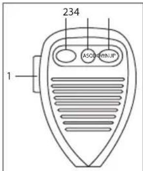
234 ASO#DOWNUP 1- Buton PTT – apasati pentru a emite
- Buton marire numar canal
- Buton activare/dezactivare functie ASQ
- Buton micsorare numar canal
INSTALARE:
natural_image
Technical line drawing of a mechanical clamp or bracket assembly with four screws and two bolts, mounted on a base (no text or symbols present)Inainte de a instala statia in masina, alegeti locatia cea mai potrivita, astfel incat sa o puteti folosi fara sa va deranjeze in timpul condusului.
text_image
UP ASQ DOWN PTT MIC- GND (braid)
- MIC (white)
- TX (yellow)
- ASQ (red)
- UP (green)
- DOWN (black)
BG:
https://www.mypni.eu/products/4390/download/certifications
EU Simplified Declaration of Conformity
SC ONLINESHOP SRL declares that CB radio PNI Escort HP 8000L ASQ is in compliance with the Directive EMC 2014/30/EU and RED 2014/53/UE. The full text of the EU declaration of conformity is available at the following Internet address: https://www.mypni.eu/products/4390/download/certifications
ES:
https://www.mypni.eu/products/4390/download/certifications
FR:
https://www.mypni.eu/products/4390/download/certifications