
90-102 - Heating NEO tools - Free user manual and instructions
Find the device manual for free 90-102 NEO tools in PDF.

| Brand | NEO tools |
| Model | 90-102 |
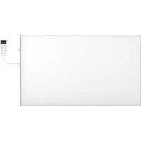
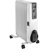
| Product type | Carbon radiant heating panel |
| Rated power | 450 W |
| Supply voltage | 220-240 V ~ 50 Hz |
| Standby power consumption | 0.4 W |
| Seasonal energy efficiency | 92% |
| Control type | Integrated touch screen and remote control |
| Functions | Adjustable thermostat, timer (shutdown), weekly programmer (up to 4 programs per day), open window detection |
| Installation | Wall or ceiling (optional brackets) |
| Minimum distance to floor | 20 cm |
| Minimum distance to ceiling | 4 cm (for ceiling installation) |
| Minimum distance to flammable objects | 0.9 m |
| Overheat protection | Yes (automatic shut-off) |
| Use in bathroom | No (except if specified zone, avoid proximity to bathtub/shower) |
| Package contents | Heating panel, instruction manual, fixing kit (4 wall plugs, 4 screws) |
| Optional accessories | Ceiling bracket 90-108, feet 90-109 |
| Maintenance and cleaning | Unplug, let cool, clean with a damp cloth, do not use abrasives |
| Repairability | Do not disassemble yourself; contact an approved service |
| Warranty | See provided warranty card |
| Country of origin | Poland (GTX Poland) |
Frequently Asked Questions - 90-102 NEO tools
User questions about 90-102 NEO tools
0 question about this device. Answer the ones you know or ask your own.
Ask a new question about this device
Download the instructions for your Heating in PDF format for free! Find your manual 90-102 - NEO tools and take your electronic device back in hand. On this page are published all the documents necessary for the use of your device. 90-102 by NEO tools.
USER MANUAL 90-102 NEO tools
natural_image
Blank white image with a small control panel on the right (no text or symbols visible)90-102/90-103/90-104

POLSKI (PL) INSTRUKCJA OBSŁUGI ORYGINALNA 3
ENGLISH (EN) TRANSLATION OF THE ORIGINAL INSTRUCTIONS .... 10
natural_image
Hand-drawn sketch of a syringe with a pointed tip, no text or symbols present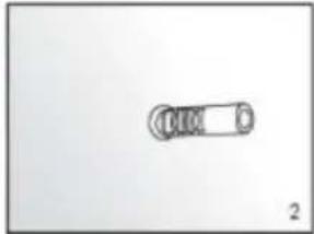
natural_image
Simple line drawing of a mechanical component with no text or symbols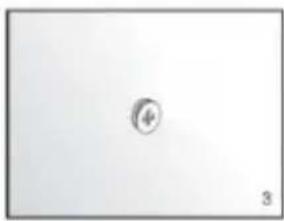
natural_image
Simple geometric shape with a small circle inside, no text or symbols present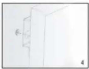
natural_image
Simple line drawing of a cabinet or cabinet with a wall-mounted door (no text or symbols)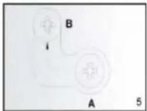


OPIS SYSTEMU KONTROLI
Panel kontrolny:
INSTRUKCJA UŻYTKOWANIA
The product is only suitable for well-insulated rooms or for occasional use.
NOTE: BEFORE USING THE EQUIPMENT, PLEASE READ THIS MANUAL CAREFULLY AND KEEP IT FOR FUTURE REFERENCE. PERSONS WHO HAVE NOT READ THE INSTRUCTIONS SHOULD NOT CARRY OUT ASSEMBLY, ADJUSTMENT OR OPERATION OF THE EQUIPMENT.
SPECIFIC SAFETY PROVISIONS
NOTE!
Read the operating instructions carefully, follow the warnings and safety conditions contained therein. The appliance has been designed for safe operation. Nevertheless: installation, maintenance and operation of the appliance can be dangerous. Following the following procedures will reduce the risk of fire, electric shock, injury and will reduce the installation time of
- This equipment may be used by children of at least 8 years of age and by people with reduced physical or mental capabilities or lack of familiarity with the equipment if supervision or instruction is provided on how to use the equipment safely so that the associated risks are understood. Children should not play with the equipment. Unsupervised children should not carry out cleaning or maintenance of the equipment.
- Never put your hands directly under the heating element! NOTE!
- To avoid overheating, do not cover the unit.
- Keep children under 3 years of age away from the appliance unless under constant supervision.
- Children between the ages of 3 and 8 can switch the appliance on/off provided it has been placed or installed in the intended normal operating position. Children should be supervised at all times unless they have received instructions on how to operate the appliance safely. Children between 3 and 8 years of age may not connect the appliance to the power supply, adjust or clean the appliance or perform maintenance.
- Caution - some parts of the appliance can become very hot and cause burns. Special attention should be paid to the presence of children and vulnerable persons.
Basic precautions should always be observed when using the device:
- Use the appliance in accordance with the operating instructions. Any use of the device not in accordance with the instructions may result in fire, electric shock or personal injury.
- Read the entire instruction manual carefully before use.
- When unpacking, check that the kit is complete.
- Children must not play with parts of the packaging, e.g. plastic bags.
- Check that the mains voltage corresponds to the unit's rated specification.
- Before use, check the power cord and plug carefully to ensure that they are not damaged.
- Do not hide the power cord under furniture, carpets or other equipment. Lay the power cord away from the traffic area.
- The appliance must not be used outdoors during precipitation, or in very wet or damp environments. The disclaimer does not apply to bathrooms.
- Please note that the appliance can become very hot. Therefore, the appliance should be placed at a safe distance (0.9m) from flammable objects such as furniture, curtains, etc.
- Do not cover the unit with, for example, a towel.
- Do not insert fingers or other objects into the device.
- Do not allow foreign bodies to enter the ventilation or outlet openings. This may cause electric shock, fire or damage to the unit.
- The appliance must not be located directly under a wall socket.
- The appliance must not be connected to the mains via a timer or programmable switch.
-
The appliance must not be placed in rooms where flammable dusts, liquids or gases are used or present.
-
If the appliance is connected via an extension cord, ensure that the extension cord is as short as possible and fully extended.
- The appliance should not be used close to a bath, shower or swimming pool. Never install the unit where there is a risk that the unit may fall into a container of water or other liquid.
- The heating panel must be positioned where switches and other controls are not within reach of a person in the bath or
- If the power supply cable is damaged, it must be replaced by the manufacturer, its representative, service or a qualified person in order to avoid danger.
- Do not connect other devices to the same mains socket to which the device is connected.
- The appliance should not be left unattended. Keep children and pets away from the appliance.
- If the appliance is not used for a long time, unplug it from the power supply. Do not leave the appliance switched on unattended. When disconnecting the appliance from the mains, pull out the plug, never pull on the power cord.
- Keep the unit away from curtains, curtains or areas where airflow is easily blocked.
- When you have finished working, allow the appliance to cool down (at least 10 minutes). Never touch the hot appliance with your bare hand.
- To prevent possible electric shock, never operate the appliance with wet hands or when there is water on the power cord.
- Do not dispose of electrical appliances with unsorted municipal waste, use separate collection points. Contact your local authorities for information on available collection systems. If electrical appliances are disposed of in landfill sites, hazardous substances can seep into the groundwater and enter the food chain, damaging your health.
- This equipment is not intended for use by persons (including children) with reduced physical or mental capabilities or without experience unless supervision or instruction is provided regarding the safe use of the equipment so that the associated risks are understood.
- Children should be supervised to ensure that they do not play with the appliance
- A ceiling-mounted appliance must be mounted at least 2.5 cm from the ceiling. The appliance must not be completely flush with the ceiling. There is a risk of the appliance overheating and burning
- If the device falls to the ground or is otherwise damaged, do not use it. In such a case, have the unit inspected and/or repaired by an authorised service centre
RATING DATA
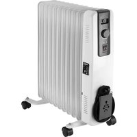
| Model | 90-102 | 90-103 | 90-104 |
| Power | 450W | 600W | 720W |
| Supply voltage | 220-240V~50Hz | ||
CONTENTS OF THE PACKAGE
• Carbon heating panel
- Operating instructions
• 1 pack of mounting accessories:
- 4x plastic pegs
- 4x metal screws
ADDITIONAL COMPONENTS TO FACILITATE INSTALLATION ARE NOT INCLUDED:
- 90-108 Ceiling bracket - suitable for 90-102 / 90-103 panels
• 90-108-1 Ceiling bracket - suitable for 90-104 panels
• 90-109 Legs 2 pcs - fit panels 90-102 / 90-103 / 90-104
ASSEMBLY INSTRUCTIONS
Open the package and pull out the heating panel together with the installation kit.
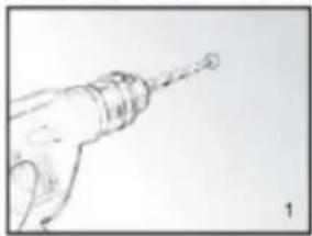
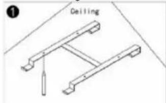
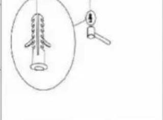
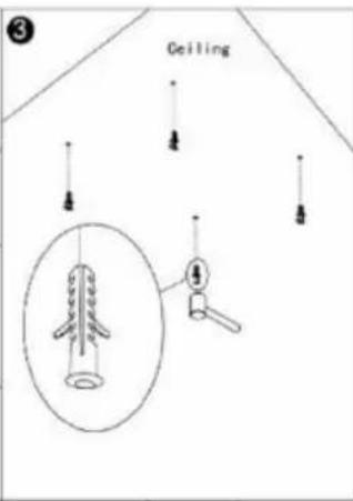
- Mark and drill holes in the wall at the appropriate location (image 1). Make sure that the distance between the holes corresponds to the spacing of the holes on the back of the heating panel.
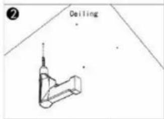
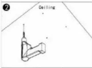
- Insert the plastic dowels into the locations of the drilled holes. (Image 2).
- Screw the metal screws into the plastic dowels (image 3).
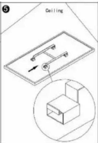
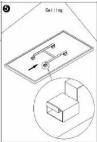
- Lift the heating panel, then aim the holes in the brackets to suit the 4 screws in the wall (image 4), then move the unit so that the screws move from position A to position B, (image 5).
- Make sure that after installation, the distance between the panel and the floor is not less than 20 cm.
natural_image
Line drawing of a hand holding a tool, possibly a drill bit or screwdriver (no text or symbols present)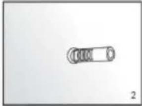
natural_image
Simple line drawing of a cylindrical object with four rings, labeled '2' at bottom right (no text or symbols on the object itself)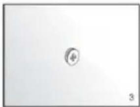
natural_image
Simple geometric shape with a small circle inside, no text or symbols present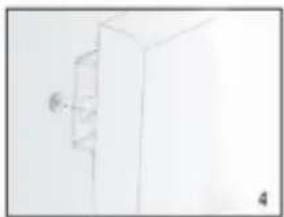
natural_image
Simple line drawing of a wall-mounted cabinet or cabinet with a wall-mounted bracket (no text or symbols)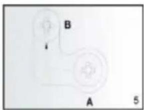
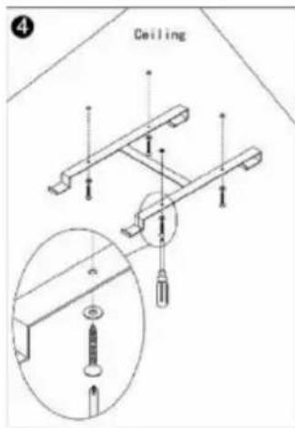
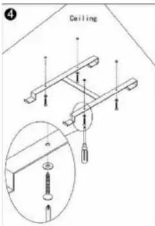
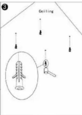
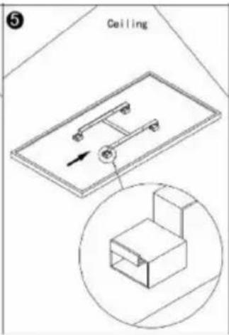
Ceiling installation:
The heating panel must be at least 20 mm away from all objects, walls, etc. The minimum distance from the ceiling is 4 cm, as this allows airflow to prevent the heating panel from overheating. The minimum distance from the bottom of the heating panel to the floor must be 185 cm. For hanging the heating panel, choose a solid, even ceiling made of heat-resistant material.
- Use the H bracket to mark the holes in the ceiling Place the H bracket in such a way that the minimum distances above are guaranteed when the heating panel is installed. Check and ensure that there are no cables in the ceiling before drilling the holes at the marked points.
- Drill the holes with a drill
- Press the plugs into the holes
- Fasten the screws with O-rings in the plugs through the holes in the H bracket.
- Mount the panel on the bracket and ensure that the panel is secured as shown in Figure 5.


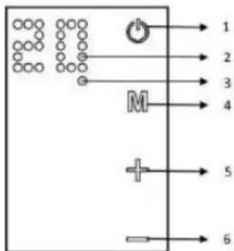
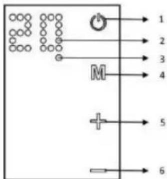
DESCRIPTION OF THE CONTROL SYSTEM
Control panel:
- On/off switch
- Display
3.Weekly programming indicator - Timer button
- Adding hours or temperature
6.Subtraction of hours or temperature
INSTRUCTIONS FOR USE
The heating panel can be controlled either from the unit, via the touch panel located in the top left corner of the unit, or by remote control
Service:
- Ensure that the heating panel is not damaged.
- Insert the plug into the socket.
- Press ON/OFF. The heating panel will switch on. The display will show the temperature.
- After use, press the ON/OFF button to switch off the appliance. Remove the plug from the socket.
Thermostat:
- When the button+ or - is pressed on the heating panel, the temperature setting on the display flashes 10 times.
- You can adjust the temperature by pressing+ or - when the temperature indicator blinks. With each press of the corresponding button the temperature will rise or fall.
- The unit will maintain the set temperature by automatically switching on or off.
- To adjust the temperature using the remote control, first press the TEMP button and then adjust the temperature setting by pressing the+ or - buttons.
Timer:
Briefly pressing the M button on the heating panel will activate the timer. You can set the time after which the heating panel will switch off by pressing the+ or - buttons. With each button press, 1 hour will be added or subtracted. After five flashes the time will be set. The number of hours and the temperature will be displayed alternately. The heating panel will switch off after the set number of hours.
To set the timer function using the remote control, first press the timer button, located below the+ button . and then adjust the temperature setting by pressing the+ or - buttons.
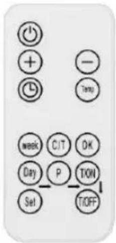
Operation of the weekly programmer by remote control The heating panel can be controlled by remote control, the functions of which are described in the figure to the right.
- Press the "ON" button to switch the panel on/off.
- Press "timer", then "+" or "-" to set the timer.
- Press "Temp" to set the temperature. Then "+" or "-"
Weekly programmer
Weekly programmer settings:
Before setting the weekly programme, the current day of the week and time must be set according to the instructions below:
Press "C/T" to set the current time, 00 will blink on the display., then press "+" or "-" to select the day of the week, 1 means Monday, 2 means Tuesday.... 7 means Sunday. Press "OK" to finish setting the day. The display will blink 00. Press or "-" to set the time from 0 to 23. Press "Temp" to finish setting the time. The display will blink 00. press "+" or" to set the time in minutes from 0 to 59. press to finish. The display will stop blinking, and indicate the temperature. Once the current time has been set, the weekly schedule can be set:
- Press the "Day" button. The display will blink 00. Press the "Day" button again. The digit 1 on the display indicates Monday. With the same button you can select the day of the week. Press to complete the day selection. 00 will blink.
- Press "P" to set the programme for a specific day. By pressing the button, you can switch between successive programmes.
- You can set up to 4 programmes for one day. Press" OK" to complete the programme selection. 00 will blink.
- Press "T/ON" to set the time at which the heating panel will switch on. The same button is responsible for selecting the next hour.
- Press "OK" to complete the switch-on time setting. 00 will blink.
- Press "T/OFF" to set the time at which the heating panel switches off. The same button is responsible for selecting the next hour.
- Press "OK" to complete the switch-off time setting. 00 will blink. After the above steps, the programme setting can be completed. Press the "Set" button to finish and exit the programmer mode.
Attention:
- To end one time group, press "Day_P_T/ON_T/OFF" in the order shown, when setting the weekly clock, all other buttons are inactive, except for the "ON" buttons "Set".
- You can exit the programmer mode by pressing the "Set" button. The settings will only be saved if all of the above steps have been completed.
PROBLEM SOLVING
If the heating panel is not working, follow the following instructions:
• Make sure the power supply in your home is working properly
- Ensure that the heater is properly connected to the mains and that the electrical socket is working properly
- If the ON/OFF button is not illuminated when the power switch on the unit is in the 'ON' position, return the unit to an authorised service centre for inspection or repair.
NOTE: IF THE UNIT DOES NOT OPERATE CORRECTLY, REFER TO THE WARRANTY CARD. DO NOT TRY IT YOURSELF
REPAIR THE APPLIANCE OR DISMANTLE IT FOR INSPECTION PURPOSES. FAILURE TO COMPLY WITH THE FOREGOING CAUTIONS MAY
AFFECT THE VALIDITY OF THE GUARANTEE AND DAMAGE THE DEVICE, AFFECTING ITS SAFE OPERATION. THERE MAY BE A RISK OF PERSONAL INJURY. IF PROBLEMS PERSIST DESPITE HAVING REPAIRED THE UNIT AT AN AUTHORISED SERVICE CENTRE, CONTACT YOUR DEALER.
CONSERVATION
Before cleaning the heating panel, switch off the appliance and allow it to cool down. Unplug the heating panel from the power supply. The outside can be wiped with a damp cloth, then dried. Do not use an abrasive or furniture cleaner as this may damage the surface. To remove the panel from the wall for cleaning or transport, carry out the reverse operation to assembly. For short periods of non-use, simply unplug the heating panel. For longer periods, the panel can be removed or covered with material.
ENVIRONMENTAL PROTECTION
Electrically-powered products should not be disposed of with household waste, but should be taken to appropriate facilities for disposal. Contact your product dealer or local authority for information on disposal. Waste electrical and electronic equipment contains substances that are not environmentally friendly. Unrecycled equipment poses a potential risk to the environment and human health.
"GTX Poland Spółka z ograniczoną odpowiedzialnością" Spółka komandytowa with its registered office in Warsaw, ul. Pograniczna 2/4 (hereinafter: "GTX Poland") informs that all copyrights to the content of this manual (hereinafter: "Manual"), including among others. All copyrights to the contents of this Manual (hereinafter referred to as "Manual"), including but not limited to its text, photographs, diagrams, drawings, as well as its composition, belong exclusively to GTX Poland and are subject to legal protection pursuant to the Act of February 4, 1994 on Copyright and Related Rights (i.e. Journal of Laws 2006 No. 90 Item 631 as amended). Copying, processing, publishing, modifying for commercial purposes the entire Manual as well as its individual elements without the written consent of GTX Poland is strictly prohibited and may result in civil and criminal liability.
| 90-102 | ||||||
| Parameter | Designation | Value | Unit | Parameter | Unit | |
| Thermal power | Type of heat output/room temperature control (select one) | |||||
| Nominal heat output | P_nom | 0,5 | kW | single level heat output, no room temperature control | Not | |
| Minimum heat output (indicative) | P_min | N/A | kW | two or more manual levels, no room temperature control | Not | |
| Maximum fixed heat output | P_max.c | 0,5 | kW | with mechanical thermostat for room temperature control | Not | |
| with electronic room temperature control | Not | |||||
| Electricity consumption for own use | electronic room temperature control + daily timer | Not | ||||
| In off mode | After | NA | W | electronic room temperature control + weekly timer | Not | |
| In standby mode | Psm | 0,4 | W | Other adjustment options (several can be selected) | ||
| In idle mode | Pidels | 0,4 | W | room temperature control with presence detection | Not | |
| In network standby mode | Pnsm | NA | W | room temperature control with open window detection | Yes | |
| Standby mode with information or status display | not | remote control option | Not | |||
| Seasonal energy efficiency of space heating in active mode | ns,on | 92 | % | adaptive actuation | Not | |
| restriction of working time | Not | |||||
| black bulb sensor | Not | |||||
| self-learning function | Not | |||||
| accuracy of control | Not | |||||
| Contact details | GTX Poland Sp. z o. o. Sp. K., ul. Pograniczna 2/4, 02-285 Warsaw | |||||
| 90-103 | ||||||
| Parameter | Designation | Value | Unit | Parameter | Unit | |
| Thermal power | Type of heat output/room temperature control (select one) | |||||
| Nominal heat output | P_nom | 0,6 | kW | single level heat output, no room temperature control | Not | |
| Minimum heat output (indicative) | P_min | N/A | kW | two or more manual levels, no room temperature control | Not | |
| Maximum fixed heat output | P_max.c | 0,6 | kW | with mechanical thermostat for room temperature control | Not | |
| with electronic room temperature control | Not | |||||
| Electricity consumption for own use | electronic room temperature control + daily timer | Not | ||||
| In off mode | After | NA | W | electronic room temperature control + weekly timer | Yes | |
| In standby mode | Psm | 0,4 | W | Other adjustment options (several can be selected) | ||
| In idle mode | Pidels | 0,4 | W | room temperature control with presence detection | Not | |
| In network standby mode | Pnsm | NA | W | room temperature control with open window detection | Yes | |
| Standby mode with information or status display | not | remote control option | Not | |||
| Seasonal energy efficiency of space heating in active mode | ns,on | 92 | % | adaptive actuation | Not | |
| restriction of working time | Not | |||||
| black bulb sensor | Not | |||||
| self-learning function | Not | |||||
| accuracy of control | Not | |||||
| Contact details | GTX Poland Sp. z o. o. Sp. K., ul. Pograniczna 2/4, 02-285 Warsaw | |||||
| 90-104 | ||||||
| Parameter | Designation | Value | Unit | Parameter | Unit | |
| Thermal power | Type of heat output/room temperature control (select one) | |||||
| Nominal heat output | P_nom | 0,7 | kW | single level heat output, no room temperature control | Not | |
| Minimum heat output (indicative) | P_min | N/A | kW | two or more manual levels, no room temperature control | Not | |
| Maximum fixed heat output | P_max.c | 0,7 | kW | with mechanical thermostat for room temperature control | Not | |
| with electronic room temperature control | Not | |||||
| Electricity consumption for own use | electronic room temperature control + daily timer | Not | ||||
| In off mode | After | NA | W | electronic room temperature control + weekly timer | Not | |
| In standby mode | Psm | 0,4 | W | Other adjustment options (several can be selected) | ||
| In idle mode | Pidels | 0,4 | W | room temperature control with presence detection | Not | |
| In network standby mode | Pnsm | NA | W | room temperature control with open window detection | Yes | |
| Standby mode with information or status display | not | remote control option | Not | |||
| Seasonal energy efficiency of space heating in active mode | ns,on | 92 | % | adaptive actuation | Not | |
| restriction of working time | Not | |||||
| black bulb sensor | Not | |||||
| self-learning function | Not | |||||
| accuracy of control | Not | |||||
| Contact details | GTX Poland Sp. z o. o. Sp. K., ul. Pograniczna 2/4, 02-285 Warsaw | |||||
natural_image
Hand-drawn sketch of a hand holding a tool, no text or symbols present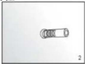
natural_image
Simple line drawing of a cylindrical object with a circular end, labeled '2' at bottom right (no text or symbols on the object itself)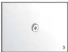
natural_image
Simple geometric shape with a small circle inside, no text or symbols present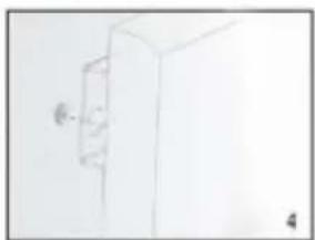
natural_image
Simple line drawing of a door with a wall-mounted knob (no text or symbols)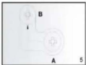
Монтаж стелі:

natural_image
Hand-drawn sketch of a syringe with a pointed tip (no text or symbols)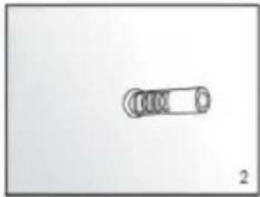
natural_image
Simple line drawing of a mechanical component with no text or symbols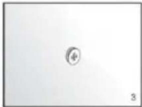
natural_image
Simple geometric shape with a small circle inside, no text or symbols present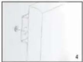
natural_image
Simple line drawing of a cabinet or cabinet with a wall-mounted door (no text or symbols)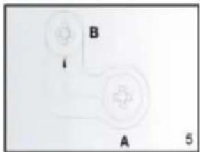
natural_image
Simple line drawing of a mechanical component with a cylindrical shaft and two hanging parts (no text or symbols)

DESCRIEREA SISTEMULUI DE CONTROL
Panou de control:
INSTRUCTIUNI DE UTILIZARE
natural_image
Hand holding a syringe with a pointed tip, no visible text or symbols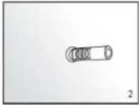
natural_image
Simple line drawing of a mechanical component with no text or symbols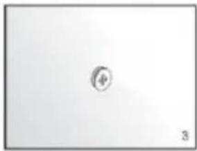
natural_image
Simple geometric shape with a small circle inside, no text or symbols present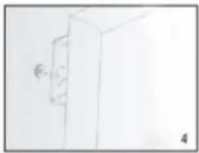
natural_image
Simple line drawing of a cabinet or cabinet with a handle and a small circular object on the side (no text or symbols)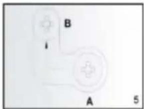
natural_image
Simple diagram with two labeled components A and B, no text or symbols present


AZ ELLENÖRZÉSI RENDSZER LEÍRÁSA
Vezérlőpanel:
HASZNÁLATI UTASÍTÁS
Heti programozó
natural_image
Hand holding a tool, possibly a drill bit or screwdriver, with no visible text or symbols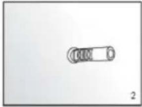
natural_image
Simple line drawing of a cylindrical object with a circular end, labeled '2' at bottom (no text or symbols on the object itself)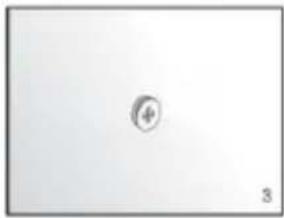
natural_image
Simple diagram with a central circle labeled 'φ' and number '3' at the bottom (no text or symbols within the diagram itself)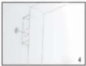
natural_image
Simple line drawing of a cabinet or cabinet with a wall-mounted door, no text or symbols present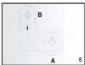
DONNÉES D'ÉVALUATION
natural_image
Line drawing of a hand holding a tool, possibly a drill bit or screwdriver (no text or symbols present)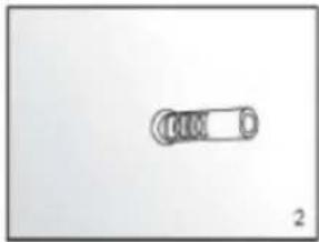
natural_image
Simple line drawing of a cylindrical object with circular ends, no text or symbols present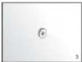
natural_image
Simple geometric shape with a small circle inside, no text or symbols present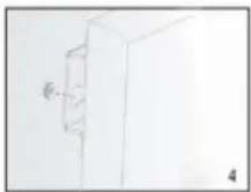
natural_image
Simple line drawing of a cabinet or cabinet with a wall-mounted door, no text or symbols present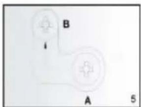
natural_image
Simple diagram of a device with labeled points A and B, no readable text or symbols beyond labels

DESCRIPTION DU SYSTEME DE CONTROLE
MODE D'EMPLOI
natural_image
Hand holding a syringe, sketch-style drawing (no text or symbols)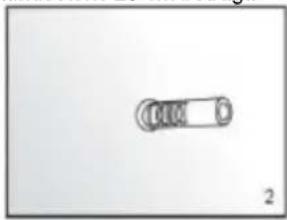
natural_image
Simple line drawing of a mechanical component with no text or symbols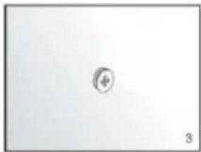
natural_image
Simple diagram with a circular symbol and the number 3, no text or labels present.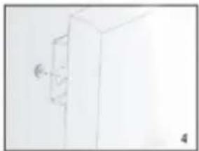
natural_image
Simple line drawing of a cabinet or cabinet with a wall-mounted door (no text or symbols)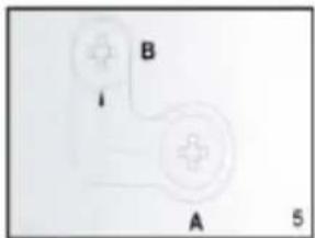


GEBRAUCHSANWEISUNG
natural_image
Sketch of a hand holding a syringe (no text or symbols)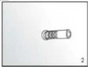
natural_image
Simple line drawing of a mechanical component with no text or symbols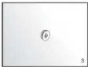
natural_image
Simple geometric shape with a small circle inside, no text or symbols present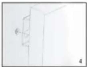
natural_image
Simple line drawing of a cabinet or cabinet with a wall-mounted fixture (no text or symbols)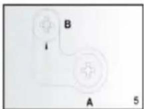
natural_image
Line drawing of a handheld electric shaver with a pointed tip (no text or symbols)
natural_image
Simple line drawing of a cylindrical object with a circular end, labeled '2' at bottom right (no text or symbols on the object itself)
natural_image
Simple diagram with a central circle and number 3, no text or symbols present
natural_image
Simple line drawing of a cabinet or cabinet with a wall-mounted door (no text or symbols)
Instalace stropu:


POPIS RÍDICÍHO SYSTÉMU
Ovládací panel:
NÁVOD K POUŽITÍ
Týdenní programátor
natural_image
Sketch of a hand holding a syringe (no text or symbols)
natural_image
Simple line drawing of a cylindrical object with a circular end, labeled '2' at bottom right (no text or symbols on the object itself)
natural_image
Simple diagram with a central circle and number 3, no text or symbols present
natural_image
Simple line drawing of a cabinet or cabinet with a door and handle, no text or symbols present.
Inštalácia stropu:
OPIS RIADIACEHO SYSTÉMU
Ovládací panel:
NÁVOD NA POUŽITIE
natural_image
Hand holding a syringe, sketch-style drawing (no text or symbols)
natural_image
Simple line drawing of a cylindrical object with a circular end, labeled '2' at bottom right (no text or symbols on the object itself)
natural_image
Simple diagram with a central circle labeled '4' and number '3' at the bottom (no text or symbols within the diagram area)
natural_image
Simple line drawing of a cabinet or cabinet with a wall-mounted door (no text or symbols)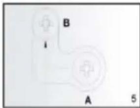
natural_image
Pure electrical circuit lines without any symbolsOPIS SUSTAVA UPRAVLJANJA
Upravljačka ploča:
UPUTE ZA KORIŠTENJE
Grijaćom pločom može se upravljati ili s uređaja, putem dodirne ploče koja se nalazi u gornjem lijevom kutu jedinice ili daljinskim upravljačem
Usluga:
Tjedni programmer
Tjedne postavke programera:
natural_image
Line drawing of a handheld electric shaver with a pointed tip (no text or symbols)
natural_image
Simple line drawing of a cylindrical object with a circular end, labeled '2' at bottom right (no text or symbols on the object itself)
natural_image
Simple diagram with a central circle and number 3, no text or symbols present
natural_image
Simple line drawing of a cabinet or cabinet with a wall-mounted door (no text or symbols)
Luby montavimas:
VALDYMO SISTEMOS APRAŠYMAS
Valdymo skydelis:
PASTABA: JEI JRENGINYS VEIKIA NETINKAMAI, KREIPKITÉS I GARANTIJOS KORTELE. NEBANDYKITE PATYS
REMONTUOTI PRIETAISĄ ARBA IŠARDYTI JI TIKRINIMO TIKSLAIS. NESILAIKANT PIRMIAU PATEIKTŲ ISPĖJIMŲ, GALI BŪTI
TURÉTI İTAKOS GARANTIJOS GALIOJIMUI IR SUGADINTI PRIETAISĄ, O TAI GALI TURÉTI İTAKOS JO SAUGIAM VEIKIMUI. GALI KILTI PAVOJUS SUSIŽEISTI. JEI PROBLEMOS IŠLIEKA NEPAISANT TO, KAD İRENGINYS BUVO REMONTUOJAMAS İGALIOTAME TECHNINĖS PRIEŽIŪROS CENTRE, KREIPKITĖS İ PARDAVĖJA.
KONSERVACIJA
natural_image
Line drawing of a handheld electric shaver with a pointed tip (no text or symbols)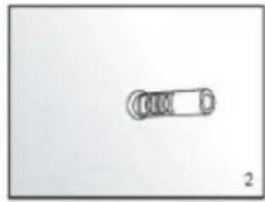
natural_image
Simple line drawing of a cylindrical object with a circular end, labeled '2' at bottom right (no text or symbols on the object itself)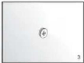
natural_image
Simple diagram with a central circle and number 3, no text or symbols present
natural_image
Simple line drawing of a cabinet or cabinet with a wall-mounted door (no text or symbols)


VADĪBAS SISTĒMAS APRAKSTS
Vadības panelis:
LIETOŠANAS INSTRUKCIJA
natural_image
Hand holding a syringe, sketch-style drawing (no text or symbols)
natural_image
Simple line drawing of a cylindrical object with a circular end, labeled '2' at bottom right (no text or symbols on the object itself)
natural_image
Simple diagram with a central circle labeled '4' and number '3' at the bottom (no text or symbols within the diagram area)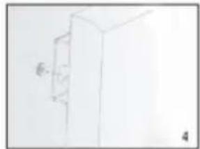
natural_image
Simple line drawing of a cabinet or cabinet with a wall-mounted door (no text or symbols)
natural_image
Pure electrical circuit lines without any symbolsVgradnja stropa:
OPIS NADZORNEGA SISTEMA
Nadzorna plošča:
- On/off stikalo
2.Prikaz
3.Weekly indikator programiranja - Timer gumb
5.Dodajanje ur ali temperatura
6.Odštevanje ur ali temperature
NAVODILA ZA UPORABO
Tedenski programmer
natural_image
Hand-drawn sketch of a hand holding a tool, no text or symbols present
natural_image
Simple line drawing of a mechanical component with no text or symbols
natural_image
Simple geometric shape with a small circle inside, no text or symbols present
natural_image
Simple line drawing of a cabinet or cabinet with a wall-mounted knob (no text or symbols)
Монтаж на тавана:


Седмичен програмист
natural_image
Hand holding a syringe with a pointed tip, no visible text or symbols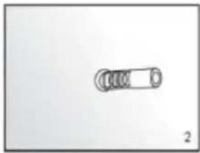
natural_image
Simple line drawing of a mechanical component with no text or symbols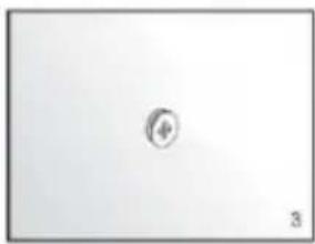
natural_image
Simple geometric shape with a small circle inside, no text or symbols present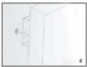
natural_image
Simple line drawing of a door with a handle and a small circular mark on the left (no text or symbols)
natural_image
Simple diagram with two labeled components A and B, no text or symbols present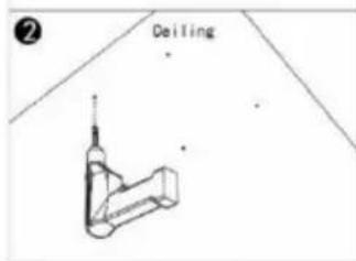

Недельни programmer
natural_image
Hand holding a syringe with a pointed tip, no visible text or symbols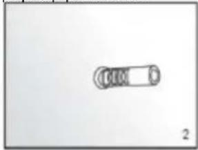
natural_image
Simple line drawing of a cylindrical object with a looped end, labeled '2' at bottom right (no text or symbols on the object itself)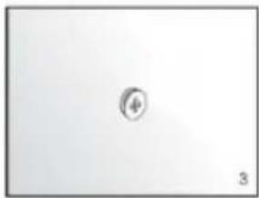
natural_image
Simple diagram with a central circular symbol and number 3, no text or labels present.
natural_image
Simple line drawing of a cabinet or cabinet with a handle and label '4' (no text or symbols on the diagram itself)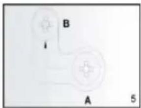
Εγκατάσταση οροφής:


ΟΔΗΓΙΕΣ ΧΡΗΣΗΣ
natural_image
Line drawing of a hand holding a tool, possibly a drill bit or probe, with no visible text or symbols.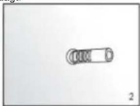
natural_image
Simple line drawing of a cylindrical object with four circular ends, no text or symbols present.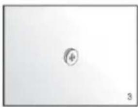
natural_image
Simple geometric shape with a small circle inside, no text or symbols present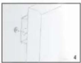
natural_image
Simple line drawing of a cabinet or cabinet with a wall-mounted knob (no text or symbols)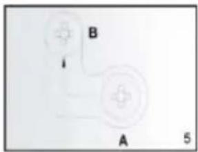
Plafondinstallatie:


BESCHRIJVING VAN HET BESTURINGSSYSTEEM
Bedieningspaneel:
GEBRUIKSAANWIJZING
natural_image
Hand-drawn sketch of a syringe with a pointed tip (no text or symbols)
natural_image
Simple line drawing of a cylindrical object with a looped end, labeled '2' at bottom (no text or symbols on the object itself)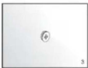
natural_image
Simple geometric shape with a small circle inside, no text or symbols present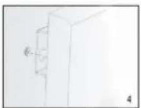
natural_image
Simple line drawing of a cabinet or cabinet with a wall-mounted door (no text or symbols)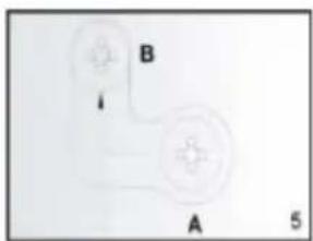
natural_image
Simple diagram of two connected devices labeled A and B, with a small arrow pointing to the B component (no text or symbols beyond labels)Instalação no teto:


Programador semanal
natural_image
Hand-drawn sketch of a syringe or tool (no text or symbols)
natural_image
Simple line drawing of a cylindrical object with a circular end, labeled '2' at bottom (no text or symbols on the object itself)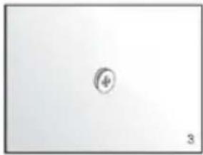
natural_image
Simple geometric shape with a small circle inside, no text or symbols present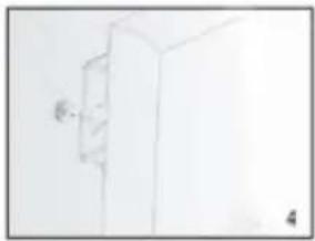
natural_image
Simple line drawing of a cabinet or cabinet with a wall-mounted door (no text or symbols)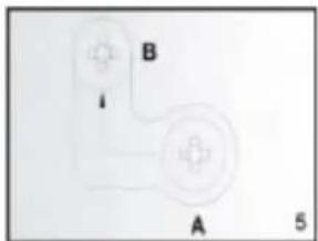


INSTRUCCIONES DE USO
Programador semanal
Ajustes del programador semanal:
natural_image
Sketch of a hand holding a syringe (no text or symbols)
natural_image
Simple line drawing of a cylindrical object with a circular end, labeled '2' at bottom right (no text or symbols on the object itself)
natural_image
Simple diagram with a central circle and number 3, no text or symbols present
natural_image
Simple line drawing of a cabinet or cabinet with a wall-mounted door (no text or symbols)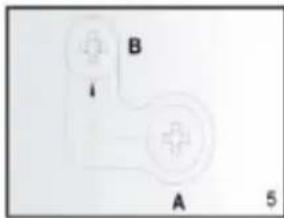
Lae paigaldamine:

KONTROLLSÜSTEEMI KIRJELDUS
Juhtpaneel:
KASUTUSJUHEND
Nädalane programmeerija
Nädalased programmeerija seaded:
- OPIS SYSTEMU KONTROLI
- INSTRUKCJA UŻYTKOWANIA
- SPECIFIC SAFETY PROVISIONS
- NOTE!
- CONTENTS OF THE PACKAGE
- ADDITIONAL COMPONENTS TO FACILITATE INSTALLATION ARE NOT INCLUDED:
- ASSEMBLY INSTRUCTIONS
- Ceiling installation:
- DESCRIPTION OF THE CONTROL SYSTEM
- INSTRUCTIONS FOR USE
- Service:
- Thermostat:
- Timer:
- Weekly programmer settings:
- Attention:
- PROBLEM SOLVING
- CONSERVATION
- ENVIRONMENTAL PROTECTION
- Монтаж стелі:
- DESCRIEREA SISTEMULUI DE CONTROL
- INSTRUCTIUNI DE UTILIZARE
- AZ ELLENÖRZÉSI RENDSZER LEÍRÁSA
- HASZNÁLATI UTASÍTÁS
- DESCRIPTION DU SYSTEME DE CONTROLE
- MODE D'EMPLOI
- GEBRAUCHSANWEISUNG
- Instalace stropu:
- POPIS RÍDICÍHO SYSTÉMU
- NÁVOD K POUŽITÍ
- Inštalácia stropu:
- OPIS RIADIACEHO SYSTÉMU
- NÁVOD NA POUŽITIE
- OPIS SUSTAVA UPRAVLJANJA
- UPUTE ZA KORIŠTENJE
- Usluga:
- Tjedne postavke programera:
- Luby montavimas:
- VALDYMO SISTEMOS APRAŠYMAS
- KONSERVACIJA
- VADĪBAS SISTĒMAS APRAKSTS
- LIETOŠANAS INSTRUKCIJA
- Vgradnja stropa:
- OPIS NADZORNEGA SISTEMA
- NAVODILA ZA UPORABO
- Монтаж на тавана:
- Εγκατάσταση οροφής:
- ΟΔΗΓΙΕΣ ΧΡΗΣΗΣ
- Plafondinstallatie:
- BESCHRIJVING VAN HET BESTURINGSSYSTEEM
- GEBRUIKSAANWIJZING
- Instalação no teto:
- INSTRUCCIONES DE USO
- Ajustes del programador semanal:
- Lae paigaldamine:
- KONTROLLSÜSTEEMI KIRJELDUS
- Juhtpaneel:
- KASUTUSJUHEND
- Nädalased programmeerija seaded:
Brand : NEO tools
Model : 90-102
Category : Heating