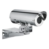
NXM36 Hi-PoE - Surveillance camera accessory Videotec - Free user manual and instructions
Find the device manual for free NXM36 Hi-PoE Videotec in PDF.


| Product Type | Camera housing for installations in harsh environments |
| Brand | Videotec |
| Model | NXM36 Hi-PoE |
| Housing material | Passivated and electropolished AISI 316L stainless steel |
| External dimensions (diameter x length) | 154 x 358 mm |
| Usable internal length | 210 mm |
| Camera window | Tempered glass, usable diameter 97 mm, thickness 4 mm |
| Net weight | 5 kg |
| Power supply | Hi-PoE (PoE+ IEEE 802.3af/at), selectable PoE Class 3 (13W) or Hi-PoE Class 4 (25W) |
| Heating power | 3W (PoE Class 3) or 7W (Hi-PoE Class 4), activation at 15°C ±3°C |
| Demisting | 1W |
| Protection (IP) | IP66, IP67, IP68, IP69 |
| Operating temperature | -20°C to +60°C (Hi-PoE version) |
| Maximum submersion | Up to -40 m (4 bar pressure) |
| Cable glands | 2x PG13.5 nickel-plated brass |
| Available options | Wiper, washer, air barrier, dual heating (not available on Hi-PoE) |
| Maintenance and cleaning | Clean with soft cloth and neutral soap diluted in water; for germanium window, use only neutral soap |
| Safety | Installation by qualified personnel, disconnect power before intervention, use certified UL/CSA cables with cross-section ≥0.14mm² |
| Spare parts and repairability | Use only VIDEOTEC original parts; repair by VIDEOTEC or under its supervision |
| Certifications | CE, EAC, EN60950-1, EN62368-1, EN50130-4, EN61000-6-3, EN60945 |
| Environmental test standards | Salt mist resistance EN60068-2-52; test at 70°C for 16h EN60068-2-2 |
Frequently Asked Questions - NXM36 Hi-PoE Videotec
User questions about NXM36 Hi-PoE Videotec
0 question about this device. Answer the ones you know or ask your own.
Ask a new question about this device
Download the instructions for your Surveillance camera accessory in PDF format for free! Find your manual NXM36 Hi-PoE - Videotec and take your electronic device back in hand. On this page are published all the documents necessary for the use of your device. NXM36 Hi-PoE by Videotec.
USER MANUAL NXM36 Hi-PoE Videotec
NXM36, NXM36 Hi-PoE, NTM36
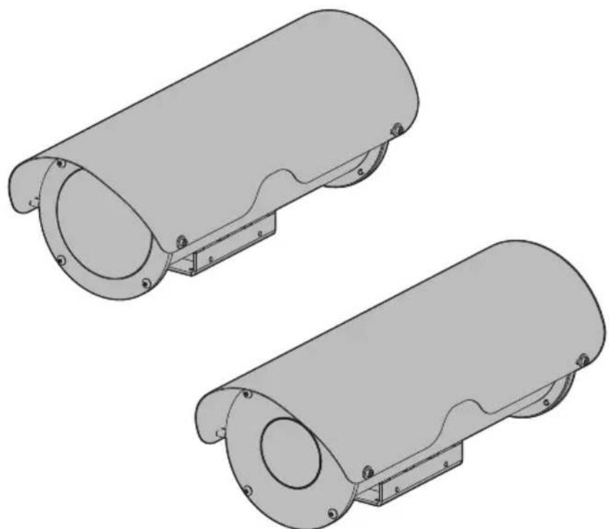
Housings for cameras installed in aggressive environments
natural_image
Two identical cylindrical mechanical components with flanged ends and mounting brackets, shown from different angles (no text or symbols)EN English - Instruction manual
IT Italiano - Manuale di istruzioni
FR Français - Manuel d'instructions
DE Deutsch - Bedienungsanleitung
RU Русский - Руководство по эксплуатации
NXM36, NXM36 Hi-PoE, NTM36
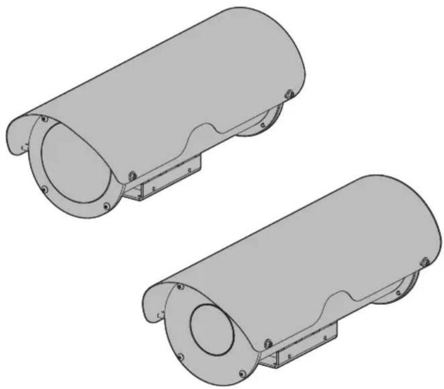
Housings for cameras installed in aggressive environments
natural_image
Two identical cylindrical mechanical components with mounting brackets and mounting holes, shown from 3D perspective (no text or symbols)Contents
1 About this manual 5
1.1 Typographical conventions .... 5
2 Notes on copyright and information on trademarks....5
3 Safety rules....5
4 Product description and type designation....7
4.1 Product marking label 7
4.2 Model identification 8
5 Preparing the product for use 9
5.1 Unpacking....9
5.2 Contents ...... 9
5.3 Safely disposing of packaging material 9
6 Installation 9
6.1 Installation mode 9
6.2 Housing opening....10
6.3 How to install the camera....10
6.3.1 12Vdc/24Vac version ....10
6.3.2 120/230Vac version....11
6.3.3 Hi-PoE version....11
6.3.3.1 Power consumption configuration....11
6.3.3.2 Operating status 12
6.4 Housing closure 12
6.5 Sunshield mounting (according to model)....12
7 Switching on 13
8 Accessories and Supports 13
9 Maintenance ....13
10 Cleaning 14
10.1 Cleaning the glass window 14
10.2 Cleaning the germanium window....14
11 Information on disposal and recycling 14
12 Technical data .... 15
12.1 NXM36 15
12.1.1 General....15
12.1.2 Mechanical....15
12.1.3 Electrical 15
12.1.4 Environment....16
12.1.5 Certifications....16
12.1.6 Certifications - Marine applications....16
12.2 NTM36....16
12.2.1 General....16
12.2.2 Mechanical....16
12.2.3 Windows for camera....17
12.2.4 Electrical 17
12.2.5 Environment....17
12.2.6 Certifications....17
13 Technical drawings 18
1 About this manual
Read all the documentation supplied carefully before installing and using this product. Keep the manual in a convenient place for future reference.
1.1 Typographical conventions

DANGER!
High level hazard.
Risk of electric shock. Disconnect the power supply before proceeding with any operation, unless indicated otherwise.

CAUTION!
Medium level hazard.
This operation is very important for the system to function properly. Please read the procedure described very carefully and carry it out as instructed.

INFO
Description of system specifications. We recommend reading this part carefully in order to understand the subsequent stages.
2 Notes on copyright and information on trademarks
The mentioned names of products or companies are trademarks or registered trademarks.
3 Safety rules

CAUTION! The electrical system to which the unit is connected must be equipped with a 20A max automatic bipolar circuit breaker. The minimum distance between the circuit breaker contacts must be 3mm (0.1in). The circuit breaker must be provided with protection against the fault current towards the ground (differential) and the overcurrent (magnetothermal).

A power disconnect device must be included in the electrical installation, and it must be very quickly recognizable and operated if needed.

CAUTION! Device installation and maintaining must be performed by specialist technical staff only.

If it is necessary to transport the device, this should be done with great care. Abrupt stops, bumps and violent impact could damage the unit or injure the user.

CAUTION! TNV-1 installation type. The installation is type TNV-1, do not connect it to SELV circuits.

CAUTION! In order to reduce the risk of fire, only use UL Listed or CSA certified cables with sections greater than or equal to 0.14mm ^2 (26AWG).
-
The manufacturer declines all responsibility for any damage caused by an improper use of the appliances mentioned in this manual. Furthermore, the manufacturer reserves the right to modify its contents without any prior notice. The documentation contained in this manual has been collected and verified with great care. The manufacturer, however, cannot take any liability for its use. The same thing can be said for any person or company involved in the creation and production of this manual.
-
Equipment intended for installation in Restricted Access Location performed by specialist technical staff.
- Before starting any operation, make sure the power supply is disconnected.
- Be careful not to use cables that seem worn or old.
- Never, under any circumstances, make any changes or connections that are not shown in this handbook. Improper use of the appliance can cause serious hazards, risking the safety of personnel and of the installation.
- Use only original spare parts. Non-original spare parts could cause fire, electrical discharge or other hazards.
- Before proceeding with installation, check the supplied material to make sure it corresponds to the order specification by examining the identification labels.
- This device was designed to be permanently secured and connected on a building or on a suitable structure. The device must be permanently secured and connected before any operation.
- Use a Class 2 listed UL tranformer, compliant with the Standards in force, only for products marked UL, powered at 24Vac.
- In the case of a 24Vac power supply, you must provide for adequate separation from the AC power supply line using double or reinforced insulation between the main power supply line and the secondary circuit.
- The separate protective earthing terminal provided on this product shall be permanently connected to earth.
-
Connect the device to a power source corresponding to the indications given on the marking label. Before proceeding with installation make sure that the power line is properly isolated. The supply voltage should never exceed the limit (±10%).
-
To comply with the main supply voltage dips and short interruption requirements, use a suitable Uninterruptable Power Supply (UPS) to power the unit.
- The safety earthing system must be carried out according to local installation dispositions.
- If the device has to be removed from the installation, always disconnect the earth cable last.
- Make especially sure that the power supply line is insulated at a sufficient distance from all the other cables, including lightning protection devices.
- Do not use the appliance in the presence of inflammable substances.
- Do not allow children or unauthorised people to use the appliance.
- The device can only be considered to be switched off when the power supply has been disconnected and the connection cables to other devices have been removed.
- Only skilled personnel should carry out maintenance on the device. When carrying out maintenance, the operator is exposed to the risk of electrocution and other hazards.
- Use only the accessories indicated by the manufacturer. Any change that is not expressly approved by the manufacturer will invalidate the guarantee.
• Take all necessary precautions to prevent the apparatus from being damaged by electrostatic discharge. - The unit has been made for connection using a 3-pole cable. To make a correct connection to the earth circuit, follow the instructions in this handbook.
- Handle the unit with great care, high mechanical stress could damage it.
4 Product description and type designation
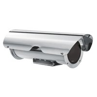
The NXM36 housing was designed for installation in highly corrosive environments such as chemical, petrochemical, marine and naval industries and on offshore platforms; internally manufactured in stainless steel AISI 316L, passivated and electropolished for maximum protection against wear.
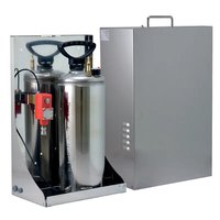
The options of wiper and water pump ensure a constant cleaning of the front window In order to prevent the formation of dust deposits, the housing can be equipped with a flange designed to create an air barrier in front of the glass. The air, normally drawn from a compressor, can be purified by the optional filter group.
For the coldest environments down to -40^ ( -40^ ), the range includes a specific version with double heater (not available on all models).
4.1 Product marking label

Before proceeding further with installation, make sure the material supplied corresponds to the order specification by examining the marking labels.

The product has a label applied in compliance with CE marking.
The label shows:
- Model identification code.
• Supply voltage (Volt). - Frequency (Hertz).
- Current consumption (Amps).
• Protection degree (IP). - Serial number.
4.2 Model identification
| NXM36 - MODEL IDENTIFICATION | |||||
| Model Number Sunshield Heater 120Vac/2 | 30Vac | Heater 12Vdc/24Vac | Double heating120Vac/230Vac | Power supplyHi-PoE | |
| NXM36D0000 - - - - - | |||||
| NXM36K0000 | √ | - - - - | |||
| NXM36D1000 - | √ | - - - | |||
| NXM36K1000 | √ | √ | - - - | ||
| NXM36K1050 | √ | - | - | √ | - |
| NXM36K2000 | √ | - | √ | - | - |
| NXM36D2700 - - - - | √ | ||||
| NXM36K2700 | √ | - - - | √ | ||
Tab. 1.
| NTM36 - MODEL IDENTIFICATION | ||||
| Model Number Sunshield | Heater 120Vac/230Vac Heater 12Vdc/24Vac Power supply Hi-PoE | |||
| NTM36K1000 | √ | √ | - | - |
| NTM36K2000 | √ | - | √ | - |
Tab. 2.
5 Preparing the product for use

Any change that is not expressly approved by the manufacturer will invalidate the guarantee.
5.1 Unpacking
When the product is delivered, make sure that the package is intact and that there are no signs that it has been dropped or scratched.
If there are obvious signs of damage, contact the supplier immediately.
When returning a faulty product we recommend using the original packaging for shipping.
Keep the packaging in case you need to send the product for repairs.
5.2 Contents
Check the contents to make sure they correspond with the list of materials as below:
- Housing
- Housing equipment
- Allen wrench
- Spacers
- Bolts and screws
- Instruction manual
- Ethernet cable (according to model)
5.3 Safely disposing of packaging material
The packaging material can all be recycled. The installer technician will be responsible for separating the material for disposal, and in any case for compliance with the legislation in force where the device is to be used.
6 Installation

Never, under any circumstances, make any changes or connections that are not shown in this handbook. Failure to follow the connection instructions that are given in the handbook may create serious safety hazards for people and for the installation.

Keep the connection diagram for future reference.
6.1 Installation mode
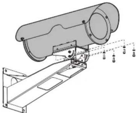
The product can be installed in various modes using the supports and various adaptors available, meeting every installation requirement.
Before closing the housing, be sure to have rightly fitted the internal slide according to the type of installation.
natural_image
Technical line drawing of a mechanical device with mounting bracket and vertical supports (no text or symbols)Fig. 1 Installation on bracket.
6.2 Housing opening
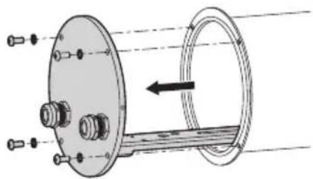
Unscrew the screws (01) on the rear flange (02) using the hexagonal wrench (03) provided.

text_image
020301Fig. 2
Slide out the rear cover plate of the housing, taking care to leave the sealing washer in its seating.
natural_image
Technical diagram of a mechanical assembly with flanged components and a central shaft (no text or symbols)Fig. 3
6.3 How to install the camera

Electrical connections must be performed with the power supply disconnected and the circuit-breaker open.

When commencing installation make sure that the specifications for the power supply for the installation correspond with those required by the device.

Do not power the product using auto-transformers.

Check that the power supply socket and cable are adequately dimensioned.

Nominal section of the cables used: consult the technical data in the relevant chapter (12 Technical data, page 15).
The power cables must be sized according to the ratio between the supply current and the distance to be covered.
Open the housing as described in the relative chapter (6.2 Housing opening, page 10).
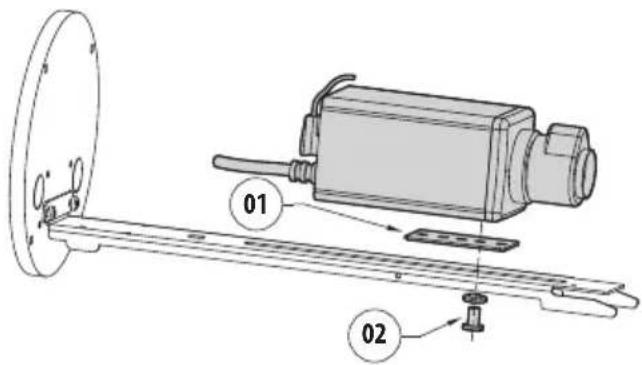
Assemble the camera on the slide using the insulating spacer (01) and the 1/4" screw and the washer (02) provided. If necessary, use the spacers to position the camera and lens correctly.
text_image
Technical diagram of a mechanical assembly with labeled parts 01 and 02, showing components like a flange and a motor-like device.Fig. 4
Insert the cables through the cable glands and electrically connect.
Ensure the cable glands are firmly fastened.
6.3.1 12Vdc/24Vac version

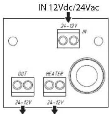
Nominal section of the cables used: from 0.2mm^2 (24AWG) up to 2.5mm^2 (13AWG).
When the power supply voltage is 12Vdc/24Vac the circuit will be connected by the terminals shown.
text_image
IN 12Vdc/24Vac 24-12V IN OUT HEATER 24-12V 24-12VHeater OUT 12Vdc/24VacOUT 12Vd
Fig. 5
6.3.2 120/230Vac version

Nominal section of the cables used: from 0.2mm^2 (24AWG) up to 2.5mm^2 (13AWG).
When the power supply voltage is 120/230Vac the circuit will be connected by the terminals shown.
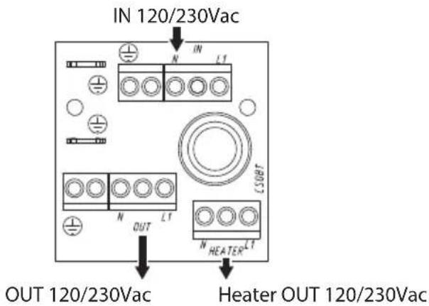
text_image
IN 120/230Vac OUT 120/230Vac HEater OUT 120/230VacFig. 6
6.3.3 Hi-PoE version
Connect the PoE cable from the Power Injector to the J1 connector.
Connect the camera to the J2 connector.
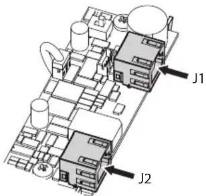
text_image
J1 J2Fig. 7
6.3.3.1 Power consumption configuration
Before powering the device, you must set the maximum power consumption of the housing operating on dip switch SW1.
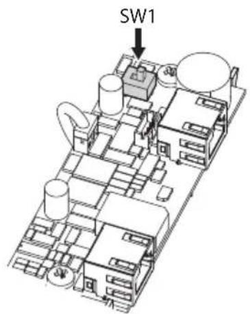
text_image
SW1Fig. 8
| POWER CONSUMPTION CONFIGURATION | |
| SW1 Maximum power | |
| POE PoE, class 3 (13W max) | |
| POE+ Hi-PoE, class 4 (25W max) | |
Tab. 3
6.3.3.2 Operating status
The LEDs shown in the figure allow to check the product's operating status.
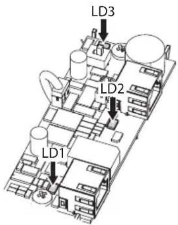
text_image
LD3 LD2 LD1Fig. 9
Refer to the table to identify the operating status.
| OPERATING STATUS | ||
| LED LED Status Apparatus Status | ||
| LD1 (Camera) | Off The camera | is not connected |
| On The camera | is correctly powered | |
| 1 flashing The | camera has a low identification resistance | |
| 2 flashings The | camera has a high identifica-tion resistance | |
| 5 flashings The | camera has an excessive energy consumption | |
| 9 flashings The | camera requires more energy than the available | |
| LD2 (Power supply) | Off The device | is not powered |
| On The device | is correctly powered | |
| LD3 (Heater) | Off Heating is inactive | |
| On Heating is active | ||
Tab. 4
6.4 Housing closure
Before closing the housing reinsert the bottom orientating the slide according to the installation required, for the right camera fitting (6.1 Installation mode, page 9).
Pay attention not to damage the gasket.
Make sure that the sealing ring is correctly fitted in its position.

Pay attention to the fixing. Tightening torque: 2.1Nm.
6.5 Sunshield mounting (according to model)
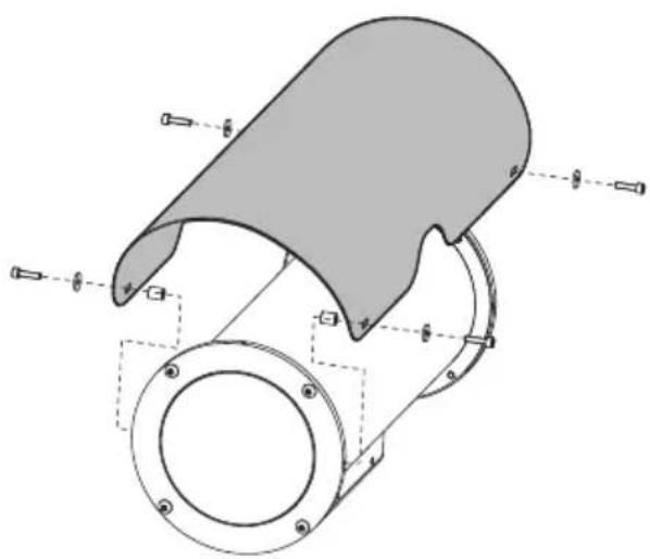
Between the sunshield and the flanges of the housing, position the spacers supplied. Fasten the sunshield to the housing with the screws and washers supplied, corresponding to the spacers.
natural_image
Technical diagram of a mechanical component with labeled parts and alignment indicators (no readable text or symbols)Fig. 10
7 Switching on

Ensure the unit and the other components of the system are appropriately closed to prevent contact with live parts.

Make sure that all parts are fastened down firmly and safely.
The unit is switched on by connecting the power supply.
To switch off the unit disconnect the power.
8 Accessories and Supports

The complete list of accessories and supports is available on the technical data sheets of the product on the website: www.videotec.com.

For further details on configuration and use, refer to the manual of the relevant accessory or support.
9 Maintenance

Before doing any technical work on the device, disconnect the power supply.

CAUTION! Device installation and maintaining must be performed by specialist technical staff only.

The manufacturer declines all liability for damage to any of the apparatus mentioned in this handbook, when resulting from tampering, use of non-original spare parts, installation, maintenance and repairs performed by non-authorised, non-skilled personnel.

For damage to any parts, repair or replacement must be done by, or under supervision of VIDEOTEC.

Whenever replacing the parts as indicated, always use VIDEOTEC original spare parts and meticulously follow the maintenance instructions supplied with every spare parts kit.

For all maintenance interventions, we recommend you return the product to the laboratory that will perform all required operations.
10 Cleaning

Frequency will depend on the type of environment in which the product is used.
10.1 Cleaning the glass window

Avoid ethyl alcohol, solvents, hydrogenated hydrocarbide, strong acid and alkali. Such products may irreparably damage the surface.
We recommend using a soft cloth with neutral soap diluted with water or specific products to clean the glasses lenses.
10.2 Cleaning the germanium window

Cleaning the window take care not to scratch or damage the outer surface treated with carbon coating. Damage to this coating could also interfere with the transparency of the surface to infrared light.
Cleaning should be done with mild soap diluted with water.
11 Information on disposal and recycling
The European Directive 2012/19/EU on Waste Electrical and Electronic Equipment (WEEE) mandates that these devices should not be disposed of in the normal flow of municipal solid waste, but they should be collected separately in order to optimize the recovery stream and recycling of the materials that they contain and to reduce the impact on human health and the environment due to the presence of potentially hazardous substances.
The symbol of the crossed out bin is marked on all products to remember this.
The waste may be delivered to appropriate collection centers, or may be delivered free of charge to the distributor where you purchased the equipment at the time of purchase of a new equivalent or without obligation to a new purchase for equipment with size smaller than 25cm (9.8in).
For more information on proper disposal of these devices, you can contact the responsible public service.
12 Technical data
12.1 NXM36
12.1.1 General
Housing manufactured in polished stainless steel (austenitic stainless alloy steel resistant to corrosion and heat):
• AISI 316L
• UNI 6900-71: X 2 Cr Ni Mo 17 12 2
• DIN 17006: X 2 Cr Ni Mo 17 13 2
- N° werkstoff: 1.4404
• AFNOR: Z2 CND 17-12
• BSI: 316S11
The screws utilised are in austenitic alloy stainless steel, corrosion and heat resistant according to the following standards:
- ISO: 7380
• AISI: 316
• ISO quality: A4
• Resistance class ISO: from 50 to 70
12.1.2 Mechanical
Approximate useful internal dimensions:
• Standard versions (WxH): 88x86mm (3.5x3.4in)
- Dual heating version (WxH): 55x86mm
• Hi-PoE versions (WxH): 88x86mm (near the glass: 88x75mm)
Internal usable length:
• Standard versions: 334mm (13.1in)
- Versions with heating and/or power supply: 245mm (9.6in)
• Hi-PoE versions: 210mm (8.3in)
External dimensions (∅xL): 154x358mm
Cable glands: 2xPG13.5 (nickel-plated brass for external connections)
Flange thickness: 6mm (0.24in) (front/back)
Gaskets: High sealing O-ring
Housing window
• Material: Tempered extra clear glass
• Usable diameter : 97mm (3.8in)
- Thick: 4mm (0.16in)
Unit weight: 5kg (11lb)
12.1.3 Electrical
Standard version
Supply voltage/Current consumption (version with heater, Ton 15°C±3°C (59°F ±5°F), Toff 22°C±3°C (72°F±5°F)):
- 12Vdc, 1.6A max
• 24Vac, 0.85A max, 50/60Hz
• 120Vac, 0.35A max, 50/60Hz
• 230Vac, 0.18A max, 50/60Hz
Version with double heater
Supply voltage/Current consumption (version with double heater, Ton 15°C±3°C (59°F ±5°F), Toff 22°C±3°C (72°F±5°F)):
• 120Vac, 0.7A max, 50/60Hz
• 230Vac, 0.35A max, 50/60Hz
Version with Hi-PoE
Power absorbed in input/Available power for camera (selectable with dip-switch)
- PoE input Class 3 (13W): PoE camera Class 2 (7W)
- Hi-PoE input Class 4 (25W): PoE camera Class 3 (13W)
Data line: 10/100Base-T
Heater
- PoE input Class 3: 3W, Ton 15^ C ± 3^ C (59°F ± 5°F), Toff 22^ C ± 3^ C (72°F ± 5°F)
- Hi-PoE input Class 4: 7W, Ton 15^ ± 3^ (59°F ±5°F), Toff 22^ ± 3^ (72°F ±5°F)
Demisting: 1W
- Compatible with IEEE 802.3af, IEEE 802.3at/PoE Plus
12.1.4 Environment
For indoors and outdoors installation
Submersible: up to -40m (-130ft) (pressure: 4bar)
Operating temperature (standard version, with heater): from -20^ ( -4^ ) up to +60^ ( 140^ )
Operating temperature (with double heater): from -40^ ( -40^ ) up to +60^ ( 140^ )
Operating temperature (Hi-PoE version): from -20°C (-4°F) up to +60°C (140°F)
Relative humidity: from 5% up to 95%
12.1.5 Certifications
Electrical safety (CE): EN60950-1, EN62368-1
Electromagnetic compatibility (CE): EN50130-4, EN61000-6-3
IP protection degree (EN60529): IP66, IP67, IP68, IP69
EAC certification
12.1.6 Certifications - Marine applications
Lloyd's Register Marine Type Approval certification:
- Test Specification Number 1 (ENV1, ENV2, ENV3, ENV5)
Electromagnetic compatibility: EN60945
Salty fog resistance: EN60068-2-52
Tested at 70^ C ( 158^ F) for 16 hours in compliance with EN60068-2-2
12.2 NTM36
12.2.1 General
Housing manufactured in polished stainless steel (austenitic stainless alloy steel resistant to corrosion and heat):
• AISI 316L
• UNI 6900-71: X 2 Cr Ni Mo 17 12 2
• DIN 17006: X 2 Cr Ni Mo 17 13 2
• N° werkstoff: 1.4404
• AFNOR: Z2 CND 17-12
- BSI: 316S11
The screws utilised are in austenitic alloy stainless steel, corrosion and heat resistant according to the following standards:
• ISO: 7380
• AISI: 316
- ISO quality: A4
• Resistance class ISO: from 50 to 70
12.2.2 Mechanical
Approximate useful internal dimensions:
• Standard versions (WxH): 88x86mm (3.5x3.4in)
Internal usable length:
- Standard versions: 334mm (13.1in)
- Versions with heating and/or power supply: 245mm (9.6in)
External dimensions (∅xL): 154x358mm (6.1x14.1in)
Cable glands: 2xPG13.5 (nickel-plated brass for external connections)
Flange thickness: 6mm (0.24in) (front/back)
Gaskets: High sealing O-ring
Unit weight: 6kg (13.3lb)
12.2.3 Windows for camera
Germanium window:
• Usable diameter: 55mm (2.1in)
- Thick: 2mm (0.08in)
- External treatment: antiscratch (Hard Carbon Coating- DLC), antireflection
- Internal treatment: antireflection
• Spectral range: from 7.5μm up to 14μm
• Medium transmittance (from 7.5μm up to 11.5μm): 90%
• Medium transmittance (from 11.5μm up to 14μm): 77%
12.2.4 Electrical
Supply voltage/Current consumption (version with heater, Ton 15°C±3°C (59°F ±5°F), Toff 22°C±3°C (72°F±5°F)):
- 12Vdc, 1.6A max
• 24Vac, 0.85A max, 50/60Hz
• 120Vac, 0.35A max, 50/60Hz
• 230Vac, 0.18A max, 50/60Hz
12.2.5 Environment
For indoors and outdoors installation
Submersible: up to -40m (-130ft) (pressure: 4bar)
Operating temperature (standard version, with heater): from -20^ ( -4^ ) up to +60^ ( 140^ )
Relative humidity: from 5% up to 95%
12.2.6 Certifications
Electrical safety (CE): EN60950-1, EN62368-1
Electromagnetic compatibility (CE): EN50130-4, EN61000-6-3
IP protection degree (EN60529): IP66, IP67, IP68, IP69
EAC certification
13 Technical drawings
The indicated measurements are expressed in millimetres.

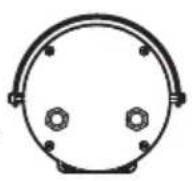
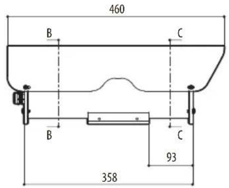
text_image
460 B C B C 93 358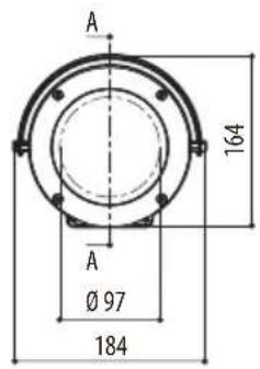
text_image
A 164 A Ø 97 184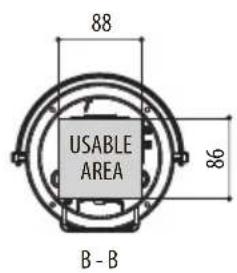
text_image
88 USABLE AREA 86 B - B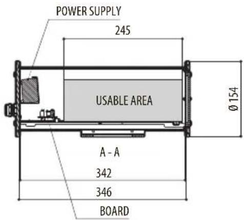
text_image
POWER SUPPLY 245 USABLE AREA Ø154 A - A 342 346 BOARD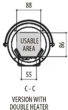
text_image
88 USABLE AREA 86 55 C - C VERSION WITH DOUBLE HEATER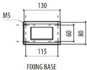
text_image
M5 130 60 80 115 FIXING BASEFig. 11 NXM36.
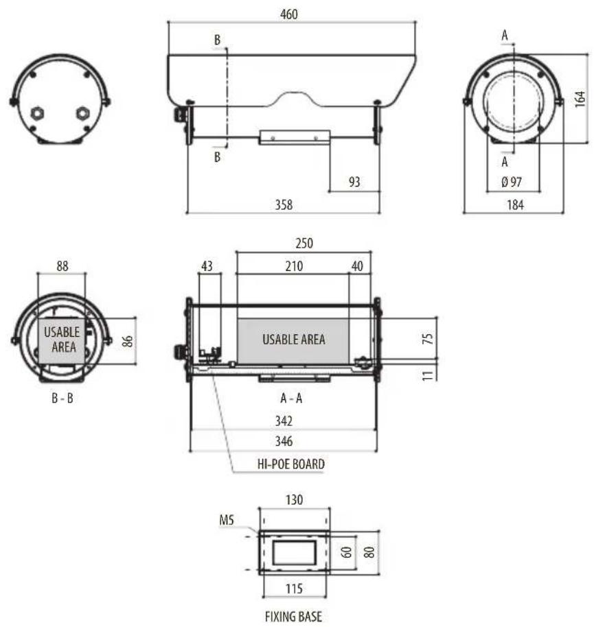
Fig. 12 NXM36 Hi-PoE.
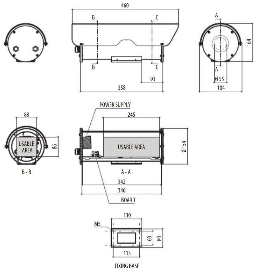
Fig. 13 NTM36.
NXM36, NXM36 Hi-PoE, NTM36
natural_image
Two identical cylindrical mechanical components with mounting brackets and mounting holes, shown from 3D perspective (no text or symbols)Sommario
natural_image
Technical line drawing of a mechanical device with mounting bracket and vertical supports (no text or symbols)natural_image
Mechanical assembly diagram showing a cylindrical component with flanged ends and a rotating shaft (no text or symbols)Fig. 3
text_image
Technical diagram of a mechanical assembly with labeled components 01 and 02, showing parts like a flange and a motor-like device.Fig. 4
text_image
IN 120/230Vac OUT 120/230Vac IN LT N OUT LT N HEATER LT LSOBT Heater OUT 120/230VacFig. 6
6.3.3 Versione Hi-PoE
natural_image
Technical diagram of a mechanical component with curved surfaces and mounting holes (no text or symbols)Fig. 10
7 Accensione

NXM36, NXM36 Hi-PoE, NTM36
natural_image
Two identical cylindrical mechanical components with mounting brackets and mounting holes, shown from 3D perspective (no text or symbols)Sommaire
natural_image
Technical line drawing of a mechanical assembly with no visible text or symbolsnatural_image
Technical diagram of a mechanical assembly with flanged components and a rotating shaft (no text or symbols)Fig. 3
text_image
Technical diagram of a mechanical assembly with labeled components 01 and 02, showing parts like a flange and a motor-like device.Fig. 4
text_image
IN 120/230Vac OUT 120/230Vac Heater OUT 120/230VacFig. 6
6.3.3 Version Hi-PoE
natural_image
Technical drawing of a mechanical component with flanged base and cylindrical housing (no text or symbols)Fig. 10
7 Allumage

Dimensions internes utiles approximatives:
12.1.5 Certifications
12.1.6 Certifications - Applications marines
Certification Lloyd's Register Marine Type Approval:
- Test Specification Number 1 (ENV1, ENV2, ENV3, ENV5)
Dimensions internes utiles approximatives:
- Versions standard (WxH): 88x86mm
12.2.6 Certifications
NXM36, NXM36 Hi-PoE, NTM36
natural_image
Two identical cylindrical mechanical components with mounting flanges and mounting brackets, shown from 3D perspective (no text or symbols)Inhaltsverzeichnis
1 Allgemeines ....5
natural_image
Technical line drawing of a mechanical device with mounting bracket and vertical supports (no text or symbols)natural_image
Technical diagram of a mechanical assembly with flanged components and a rotating shaft (no text or symbols)Abb. 3
text_image
Technical diagram of a mechanical assembly with labeled components 01 and 02, showing parts like a flange and a motor-like device.Abb. 4
text_image
IN 120/230Vac N IN L1 C50BT N OUT L1 N HEATER L1OUT 120/230Vac
Heater OUT 120/230Vac
Abb. 6
6.3.3 Hi-PoE-Version
natural_image
Technical diagram of a mechanical component with curved surfaces and mounting holes (no text or labels)Abb. 10
7 Einschaltung

NXM36, NXM36 Hi-PoE, NTM36
natural_image
Two identical cylindrical mechanical components with mounting brackets and mounting holes, shown from 3D perspective (no text or symbols)natural_image
Technical line drawing of a mechanical assembly with no visible text or symbolsnatural_image
Technical diagram of a mechanical assembly with flanged components and a central shaft (no text or symbols)Рис. 3
text_image
Technical diagram of a mechanical assembly with labeled components 01 and 02, showing parts like a flange and a motor-like device.Рис. 4
text_image
IN 120/230Vac N IN L1 OUT 120/230Vac Heater OUT 120/230VacРис. 6
6.3.3 Hi-PoE-модель
natural_image
Technical diagram of a mechanical component with curved and flanged parts, no visible text or symbolsРис. 10
7 Включение

text_image
Black and white barcode image with vertical lines on both sides
Headquarters Italy VIDEOTEC s.r.l.
Via Friuli, 6 - I-36015 Schio (VI) - Italy
Tel. +39 0445 697411 - Fax +39 0445 697414
Email: info@videotec.com
www.videotec.com