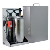
WASEX - Washing machine Videotec - Free user manual and instructions
Find the device manual for free WASEX Videotec in PDF.


| Product Type | Washing kit for video surveillance system |
| Brand | Videotec |
| Model | WASEX |
| Category | Washing machine (industrial use) |
| Use | Washing camera windows in explosive areas (ATEX) |
| Tank capacity | 10 liters |
| Maximum pressure | 6 bar |
| Water lift height | 20 m (4 bar) with supplied hose; 30 m (6 bar) with optional hose |
| Discharge hose | 20 m, antistatic, supplied as standard |
| Power supply | 24 Vac / 24 Vdc |
| Housing material | Stainless steel AISI 316L |
| Cable entries | 1 or 2 x 1/2" NPT depending on version |
| Certifications | ATEX, EAC Ex, IECEx, INMETRO, cULus depending on version |
| Operating temperature | -40°C to +60°C (solenoid valve); -40°C to +80°C (pressure switch on versions with) |
| Relative humidity | 5% to 95% |
| Kit contents | Window washing kit, bracket, hose, clamps, sealing rings, manuals |
| Installation | Wall or floor, with flanges or angle adapter; tank in vertical position |
| Regular maintenance | Tank refilling, cable inspection |
| Cleaning | Damp cloth; do not use compressed air; dust < 5 mm |
| Safety | Explosion-proof (ATEX), mandatory grounding, installation by qualified personnel |
| Spare parts | Available on request, serial number required |
| Recycling | Compliant with WEEE (2012/19/EU): do not dispose of with household waste |
Frequently Asked Questions - WASEX Videotec
User questions about WASEX Videotec
0 question about this device. Answer the ones you know or ask your own.
Ask a new question about this device
Download the instructions for your Washing machine in PDF format for free! Find your manual WASEX - Videotec and take your electronic device back in hand. On this page are published all the documents necessary for the use of your device. WASEX by Videotec.
USER MANUAL WASEX Videotec
Explosion-proof wash system
natural_image
Line drawing of a rectangular industrial enclosure with ventilation slots and a handle (no text or symbols)EN English - Instruction manual
Explosion-proof wash system
natural_image
Line drawing of a rectangular industrial enclosure with ventilation slots and a handle (no text or symbols)Contents
1 About this manual....5
1.1 Typographical conventions .... 5
2 Notes on copyright and information on trademarks....5
3 Safety rules ....5
4 Product description and type designation....7
4.1 Product overview 8
4.2 Product marking label......8
4.3 Model identification....9
5 Preparing the product for use....10
5.1 Unpacking....10
5.2 Contents 10
5.3 Safely disposing of packaging material....10
6 Installation....10
6.1 Product opening....10
6.2 Frame perforation....11
6.2.1 Assembly of the seal rings....11
6.3 Installation options 11
6.3.1 Wall or floor fastening 11
6.3.2 Fixing with corner adaptor module or pole 12
6.4 Delivery pipe connection 12
6.5 Ground connection....13
6.5.1 Earthing equipotential connection....13
6.6 Connection of the solenoid valve....13
6.7 Pressure switch connection 13
6.8 Connection to PTZ (MAXIMUS MPX, MAXIMUS MPX SERIES2) 13
6.8.1 Connection of the solenoid valve to the PTZ (MAXIMUS MPX, MAXIMUS MPX SERIES2)....14
6.8.2 Connection of the pressure switch to the PTZ (MAXIMUS MPX, MAXIMUS MPX SERIES2) 14
6.9 Connection to the camera (MAXIMUS MVX) 15
6.9.1 Connection of the solenoid valve to the camera (MAXIMUS MVX) 15
6.9.2 Connection of the pressure switch to the camera (MAXIMUS MVX) 15
6.10 Connection to the housing (MAXIMUS MHX) 16
6.10.1 Connection of the solenoid valve to the housing (MAXIMUS MHX)....16
6.10.2 Connection of the pressure switch to the housing (MAXIMUS MHX) 16
6.11 Filling the tank.... 17
6.11.1 Pressurise the tank using the manual pump....17
6.11.2 Pressurise the tank using the compressed air valve 17
6.11.3 Product closure 18
6.12 Washer installation (MAXIMUS MPX, MAXIMUS MPX SERIES2)....18
6.12.1 Installation options....19
6.13 Washer installation (MAXIMUS MVX)....20
6.14 Washer installation (MAXIMUS MHX) 21
7 Maintenance....22
7.1 Routine maintenance....22
7.1.1 Filling the tank....22
7.1.2 Inspecting the cables 22
8 Cleaning 22
8.1 Routine cleaning....22
9 Information on disposal and recycling 22
10 Technical data....23
10.1 Mechanical....23
10.2 Electrical....23
10.3 Environment 23
10.4 Certifications - Marine applications 23
11 Technical drawings....24
1 About this manual
Read all the documentation supplied carefully before installing and using this product. Keep the manual in a convenient place for future reference.
1.1 Typographical conventions

DANGER!
Explosion hazard.
Read carefully to avoid danger of explosion.

DANGER!
High level hazard.
Risk of electric shock. Disconnect the power supply before proceeding with any operation, unless indicated otherwise.

CAUTION!
Medium level hazard.
This operation is very important for the system to function properly. Please read the procedure described very carefully and carry it out as instructed.

INFO
Description of system specifications.
We recommend reading this part carefully in order to understand the subsequent stages.
2 Notes on copyright and information on trademarks
The mentioned names of products or companies are trademarks or registered trademarks.
3 Safety rules

DANGER!
Explosion hazard.
Read carefully to avoid danger of explosion.
- Installation and maintenance of the appliance must be carried out by specialist technical staff in compliance with the applicable reference standard EN/IEC 60079-14, EN/IEC 60079-17 and national standards.
- Do not open the device when powered and in explosive atmosphere.
- Use appropriate tools for the installation. The particular nature of the site where the device is to be installed may mean special tools are required for installation.
- Make all connections, installation and maintenance work in a non-explosive atmosphere.
- The equipotential connection is mandatory to avoid the risk of ignition of products installed in potentially explosive environments.
- Before powering the product in an explosive atmosphere, ensure the cover of each component is closed correctly.
- Make sure that all the equipment are certified for the application and for the environment in which they will be installed.
- Any change that is not expressly approved by the manufacturer will invalidate the warranty.

DANGER!
High level hazard.
Risk of electric shock. Disconnect the power supply before proceeding with any operation, unless indicated otherwise.
- Electrical connections must be performed with the power supply disconnected and the circuit-breaker open.
- A power disconnect device must be included in the electrical installation, and it must be very quickly recognizable and operated if needed.
- The device can only be considered to be switched off when the power supply has been disconnected and the connection cables to other devices have been removed.
- Be careful not to use cables that seem worn or old.
- All the cables must comply with IEC60332-1-2, IEC 60332-1-3 and IEC/EN60079-14.
- This equipment is not suitable for use in locations where children are likely to be present.

CAUTION!
Medium level hazard.
This operation is very important for the system to function properly. Please read the procedure described very carefully and carry it out as instructed.
- Ensure the installation meets local specifications.
- Make connections and tests in the laboratory before carrying out installation on site. Use appropriate tools for the purpose.
- Check that the power supply socket and cable are adequately dimensioned.
- Use suitable cables that can withstand the operating temperatures.
- All disconnected cables must be electrically isolated.
- Make sure the product is to be secured to building before operation.
- The manufacturer declines all liability for damage to any of the apparatus mentioned in this handbook, when resulting from tampering, use of non-original spare parts, installation, maintenance and repairs performed by non-authorised, non-skilled personnel.
- For damage to any parts, repair or replacement must be done by, or under supervision of VIDEOTEC.
- This product must only be repaired by suitably trained personnel or under the supervision of VIDEOTEC personnel in accordance with the foreseen terms and conditions: IEC/EN60079-19.
- Only use original VIDEOTEC spare parts. Strictly adhere to the maintenance instructions attached to each replacement kit.
- For technical services, consult only and exclusively authorized technicians.
- We strongly recommend using only approved brackets and accessories during installation.

INFO
Description of system specifications. We recommend reading this part carefully in order to understand the subsequent stages.
- Given the considerable weight of the system, use an appropriate transport and handling system. The staff must carry out the handling of the product in compliance with the common accident prevention standards.
- Before proceeding with installation, check the supplied material to make sure it corresponds to the order specification by examining the identification labels.
- The equipment is intended for installation in a Restricted Access Area by specialist technical staff.
- The manufacturer declines all responsibility for any damage caused by an improper use of the appliances mentioned in this manual. Furthermore, the manufacturer reserves the right to modify its contents without any prior notice. The documentation contained in this manual has been collected and verified with great care. The manufacturer, however, cannot take any liability for its use. The same thing can be said for any person or company involved in the creation and production of this manual.
- Since the user is responsible for choosing the surface to which the unit is to be anchored, we do not supply the fixing devices for attaching the unit firmly to the particular surface. The installer is responsible for choosing fixing devices suitable for the specific purpose on hand. Use methods and materials capable of supporting at least 4 times the weight of the device.
4 Product description and type designation
The WASEX washer pump is an important element for effective video surveillance in hazardous areas because it guarantees sharp images in all environmental conditions and reduces the need for maintenance.
The WASEX system is designed for the MAXIMUS series and is also compatible with third-party products.
The kit is composed of a 10-litre stainless steel tank with an explosion-proof certified solenoid valve and some versions of the product also have an explosion-proof certified pressure switch.
The WASEX version with pressure switch has a clean contact that switches when the tank pressure goes under a preset value.
The pressure switch can be connected to the alarm of the MAXIMUS series cameras or it can be connected directly to the alarm of the main electric box, to warn operators to reset the pressure and level of the water.
4.1 Product overview
The main parts of the product are illustrated below:
- Casing.
- Frame.
- 10l tank.
- Pressure switch (only in versions which include it).
- Solenoid valve.
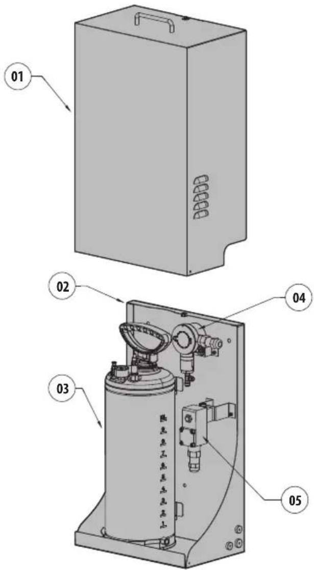
Fig. 1

The shape of the solenoid valve may change according to washer pump model.
4.2 Product marking label
The washer pump marking is defined by the marking of the solenoid valve and the pressure switch (if present).
The markings of the solenoid valve and the pressure switch (if present) are indicated on the plates applied to the components.
The product serial number is indicated in the label positioned as shown in the figure.
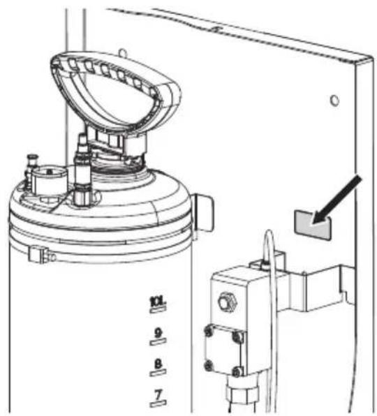
natural_image
Technical line drawing of a mechanical device with numbered components and an arrow pointing to a component (no text or symbols present)Fig. 2
4.3 Model identification
WASEX2T4AT: 10l tank with integrated manual pump, controlled by a certified solenoid valve (ATEX), delivery head up to 30m (98ft), with 20m (66ft) antistatic water delivery pipe, IN 24Vac/24Vdc
WASEX2T4ATPR: 10l tank with integrated manual pump, controlled by a certified solenoid valve and pressure switch (ATEX), delivery head up to 30m (98ft), with 20m (66ft) antistatic water delivery pipe, IN 24Vac/24Vdc
WASEX2T4GOR: 10l tank with integrated manual pump, controlled by a certified solenoid valve (EAC Ex), delivery head up to 30m (98ft), with 20m (66ft) antistatic water delivery pipe, IN 24Vac/24Vdc
WASEX2T4IC: 10l tank with integrated manual pump, controlled by a certified solenoid valve (ATEX, IECEx), delivery head up to 30m (98ft), with 20m (66ft) antistatic water delivery pipe, IN 24Vac/24Vdc
WASEX2T4IN: 10l tank with integrated manual pump, controlled by a certified solenoid valve (INMETRO), delivery head up to 30m (98ft), with 20m (66ft) antistatic water delivery pipe, IN 24Vac/24Vdc
WASEX2T4UL: 10l tank with integrated manual pump, controlled by a certified solenoid valve (cULus), delivery head up to 30m (98ft), with 20m (66ft) antistatic water delivery pipe, IN 24Vac/24Vdc
| WASEX - CERTIFICATIONS AND MARKINGS | |||
| Part number | Certification | Marking | Ambient temperature |
| WASEX2T4AT ATEX | (Solenoid valve) | 2 II GD Ex d IIC T6 or T5 or T4 GbEx tb IIIC T80°C or 95°C or T130°C Db IP66 | -40°C ≤ Ta ≤ +35°C or +50°C or +60°C |
| WASEX2T4GOR EAC | Ex (Pumping unit) | II Gb c IIC T6...T4 XIII Db c IIIC T85°C...T130°C X | -40°C ≤ Ta ≤ +35°C or +50°C or +60°C |
| EAC Ex (Solenoid valve) | 1Ex db IIC T6...T4 Gb XEx tb IIIC T80°C...T130°C Db | -40°C ≤ Ta ≤ +35°C or +50°C or +60°C | |
| WASEX2T4IC ATEX | (Solenoid valve) | II 2G Ex db IIC T6...T4 GbII 2D Ex tb IIIC T85°C...T135°C Db | -60°C ≤ Tamb ≤ +65°C or +80°C or +100°C |
| IECEx (Solenoid valve) | Ex db IIC T6...T4 GbEx tb IIIC T85°C...T135°C Db | ||
| WASEX2T4IN INMETRO (Sole - noid valve) | Ex d IIC T4 Gb IP66Ex tb IIIC T135°C Db IP66 | -40°C ≤ Ta ≤ +60°C | |
| WASEX2T4ATPR | ATEX (Pressure switch) | 2 II G Ex d IIC T6 GbEx d IIC T5 Gb2 II D Ex tb IIIC T 75°C DbEx tb IIIC T 90°C Db | -35°C ≤ Ta ≤ +65°C or +80°C |
| ATEX (Solenoid valve) | 2 II GD Ex d IIC T6 or T5 or T4 GbEx tb IIIC T80°C or 95°C or T130°C Db IP66 | -40°C ≤ Ta ≤ +35°C or +50°C or +60°C | |
| WASEX2T4UL | cULus (Solenoid valve) | CLASS I, DIV I, GROUP B, C, DCLASS II, DIV I, GROUP E, F, GCLASS III, DIV I | -60°C ≤ Ta ≤ 55°C FOR T6-60°C ≤ Ta ≤ 70°C FOR T5-60°C ≤ Ta ≤ 100°C FOR T4 |
Tab. 1 ^1 The assembly can be installed in the following areas:
Zone 1, IIC, T6/T5/T4, ambient temperature from -35^ up to +35^ , +50^ , +60^ .
Zone 21, IIIC, T80°C/T95°C/T130°C, ambient temperature from -35°C up to +35°C, +50°C, +60°C.
5 Preparing the product for use

Any change that is not expressly approved by the manufacturer will invalidate the warranty.
5.1 Unpacking
When the product is delivered, make sure that the package is intact and that there are no signs that it has been dropped or scratched.
If there are obvious signs of damage, contact the supplier immediately.
When returning a faulty product we recommend using the original packaging for shipping.
Keep the packaging in case you need to send the product for repairs.
5.2 Contents
Check the contents to make sure they correspond with the list of materials as below:
- Windows washing kit
• Support for the delivery pipe - Locking bracket of the delivery pipe
- Bolts and screws
- Washer semi-rigid pipe (with nozzle)
- Pipe connector
- Stainless steel clamps
• Delivery pipe (length: 20m) - Sealing rings
- Instruction manual
- Solenoid valve user and installation manual
- Use and installation manual of the pressure switch (only in versions which include it)
5.3 Safely disposing of packaging material
The packaging material can all be recycled. The installer technician will be responsible for separating the material for disposal, and in any case for compliance with the legislation in force where the device is to be used.
6 Installation

Before carrying out any type of intervention, read the "Safety rules" chapter of this manual.
6.1 Product opening

It is possible to install or service the pump without removing the tank (Fig. 4, page 10). To remove the tank (01), release the metal clamps (02) and disconnect the connecting pipe (03).
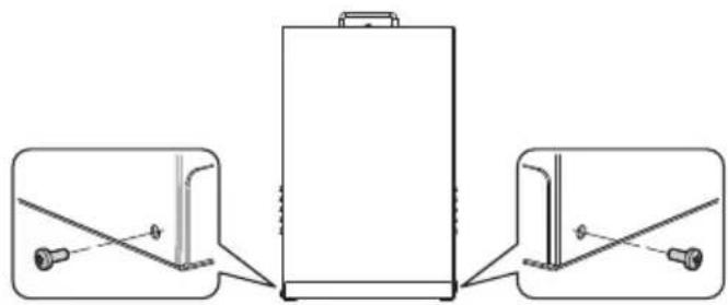
Unscrew the 2 side screws to open the cover.
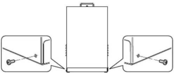
natural_image
Technical line drawing of a battery with three views showing internal components and mounting points (no text or symbols)Fig. 3
Undo the safety screw (04) and lift the guard (05).
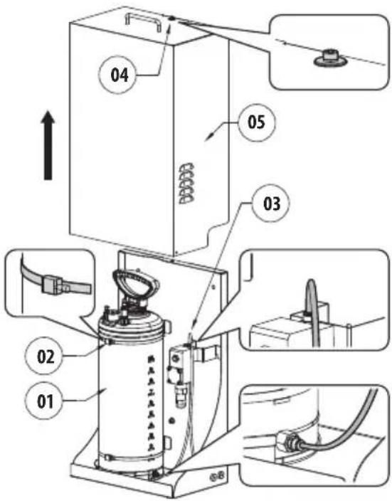
Fig. 4
6.2 Frame perforation
The sides and the bottom of the product have pre-drilled holes for passage of the electrical conductors and the delivery pipe. The holes made for installation should be protected by the sealing rings provided.
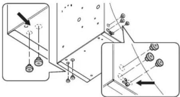
Fig. 5
6.2.1 Assembly of the seal rings

During assembly, be careful not to damage the rubber and thereby reduce its air-tightness.
Insert the conical part of the sealing ring in the hole. Tighten the conical part of the sealing ring with a pliers or a similar tool.
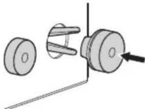
natural_image
Mechanical assembly diagram showing a shaft and housing with a directional arrow (no text or symbols)Fig. 6
Pull the sealing ring allowing it to pass through the hole until the conical part is completely out. In the final position, the sealing ring should completely close the passage hole.
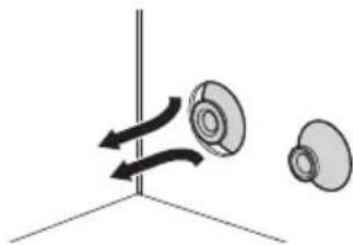
natural_image
Diagram showing two mechanical components with rotational arrows, no text or symbols presentFig. 7
| RATIO BETWEEN THE DIMENSIONS OF THE SEALING RINGS ANDTHE DIAMETER OF THE USABLE CABLES | ||
| Sealing ring ∅ passage (mm) | age hole (mm) | ∅ cable (mm) |
| M16 16.5 From 5 up to 9 | ||
| M20 20.5 From 8 up to 12 | ||
Tab. 2
6.3 Installation options

The product can only be installed in a vertical position.
The product can be installed with different brackets and supports. Remember to exclusively use brackets and accessories approved for installation.
6.3.1 Wall or floor fastening
The product can be fastened directly to the wall or the floor using the holes present on the frame.
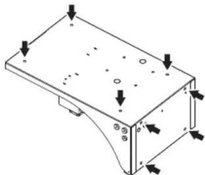
natural_image
Isometric technical drawing of a mechanical housing component with mounting holes and directional arrows indicating force or movement (no text or symbols)Fig. 8
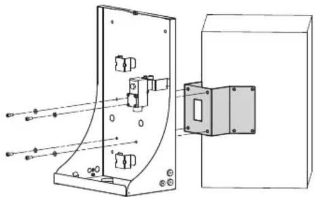
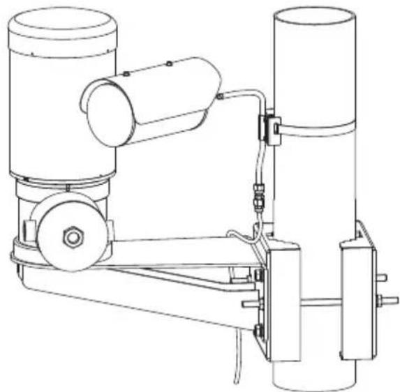
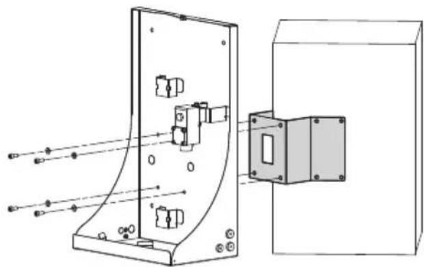
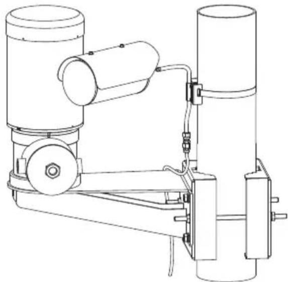
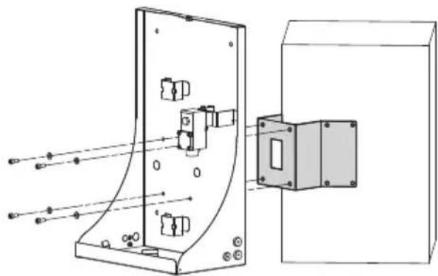
6.3.2 Fixing with corner adaptor module or pole

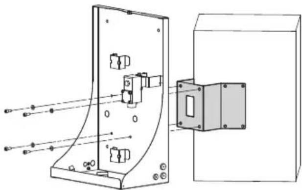
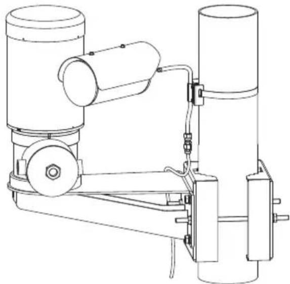
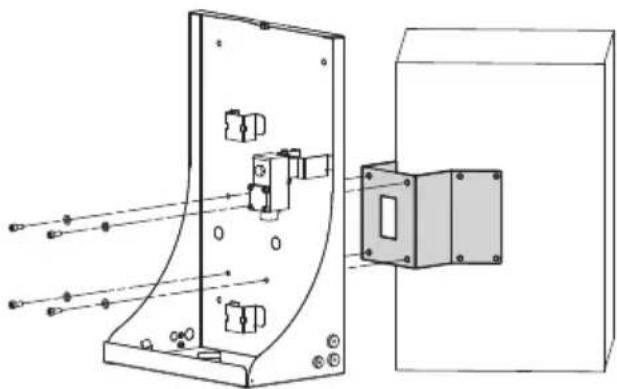
Pay attention to the fixing. Tightening torque: 16.5Nm.
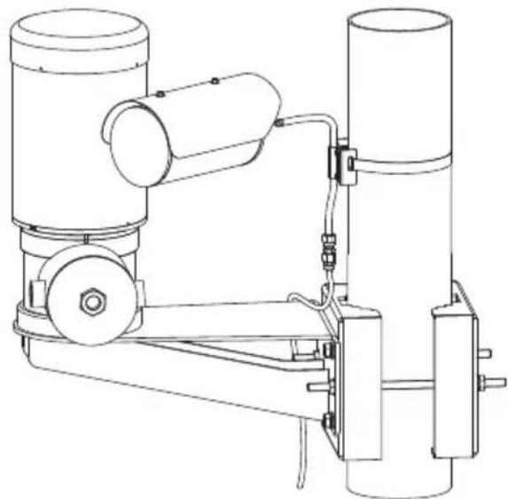
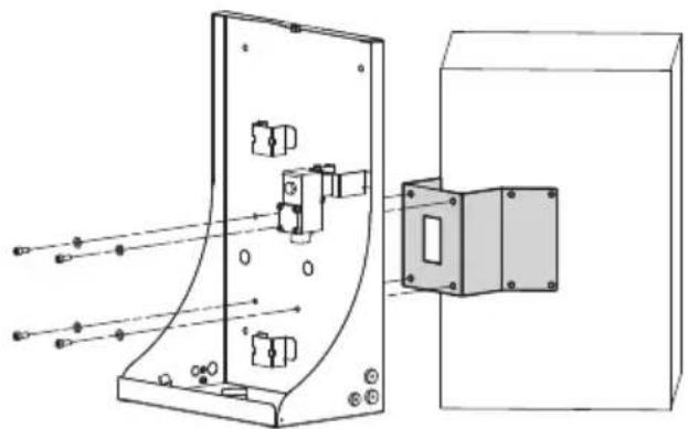
The product can also be assembled on the pole collar or corner adaptor.
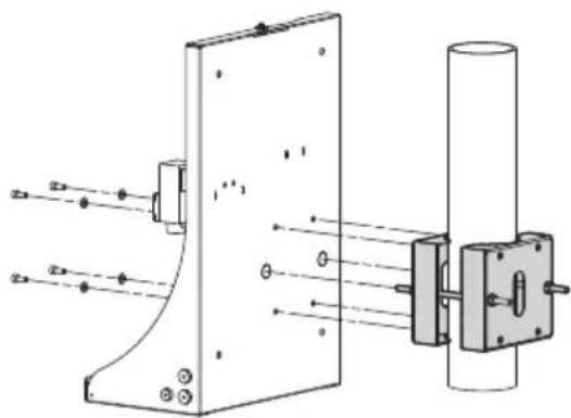
natural_image
Technical line drawing of a mechanical assembly with mounting bracket and cylindrical component (no text or symbols)Fig. 9 WASEX+NXCOL.
natural_image
Technical line drawing of a mechanical assembly with mounting brackets and a separate housing (no text or symbols)Fig. 10 WASEX+NXCW.
6.4 Delivery pipe connection
Connect the delivery pipe (01), passing it through the seal ring (02).
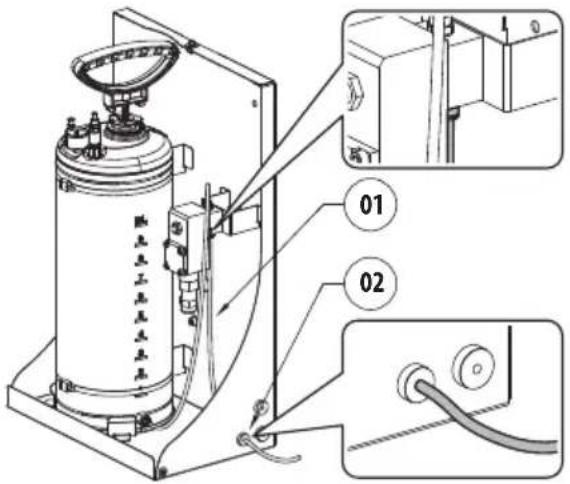
Fig. 11
6.5 Ground connection
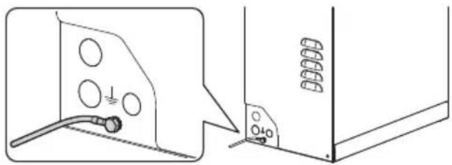
6.5.1 Earthing equipotential connection
The equipotential connection must be carried out using an external cable with a minimum 4mm^2 section (11AWG).
Connect the cable for the earthing equipotential connection with the eyelet terminal supplied (suitable for cables with 4mm^2 (11AWG) up to 6mm^2 (9AWG) section).
Fasten the eyelet using the screw (M5) and lock washer
Characteristics of the M5 screw:
- Material: A4 Class 70
- Screw head: ISO 4762
• Length: 8mm (0.3in)
natural_image
Technical line drawing showing two views of a mechanical or electrical component with circular holes and a cable (no text or symbols)Fig. 12

The solenoid valve and the pressure switch (if assembled) are connected to the ground as per the instruction of the single product and in compliance with EN IEC 60079-14.
6.6 Connection of the solenoid valve

When commencing installation make sure that the specifications for the power supply for the installation correspond with those required by the device.
Refer to the use and maintenance manual of the solenoid valve for further information.
6.7 Pressure switch connection
Refer to the use and maintenance manual of the pressure switch for further information.
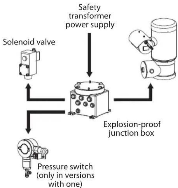
6.8 Connection to PTZ (MAXIMUS MPX, MAXIMUS MPX SERIES2)

To install electrical connections between the products, use the communication box by VIDEOTEC, MAXIMUS MBX or MAXIMUS MBA, alternatively use an explosion-proof junction box with equivalent characteristics.
flowchart
graph TD
    A["Solenoid valve"] --> B["Explosion-proof junction box"]
    C["Pressure switch (only in versions with one)"] --> B
    D["Safety transformer power supply"] --> B
Fig. 13
6.8.1 Connection of the solenoid valve to the PTZ (MAXIMUS MPX, MAXIMUS MPX SERIES2)

The RL2 relay in the PTZ can withstand a voltage of up to 30Vac or 60Vdc. Turn off one of the supply poles of the solenoid valve via the RL2 relay of the PTZ. Consult the PTZ manual.
- Connect as in the diagram below (Fig. 14, page 14).

The solenoid valve can be powered to 24Vac or 24Vdc with an isolated transformer or isolated converter.
The polarity of the voltage, applied to the power terminal, is irrelevant.

Fig. 14
6.8.2 Connection of the pressure switch to the PTZ (MAXIMUS MPX, MAXIMUS MPX SERIES2)
Use the auto-powered alarm input AL1 to connect the pressure switch to MPX (consult the PTZ manual).
Connect as in the diagram below (Fig. 15, page 14).
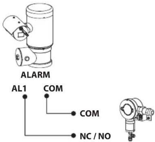
Fig. 15
6.9 Connection to the camera (MAXIMUS MVX)

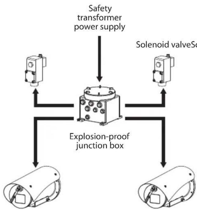
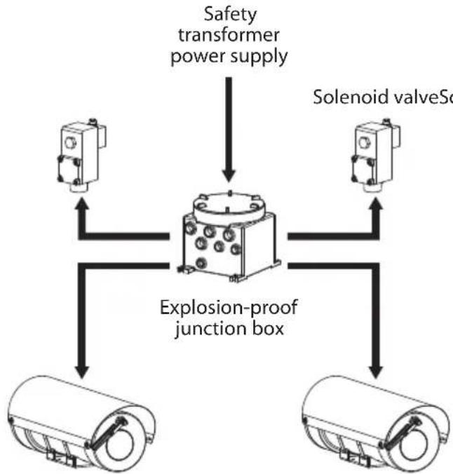
To install electrical connections between the products, use the communication box by VIDEOTEC, MAXIMUS MBX or MAXIMUS MBA, alternatively use an explosion-proof junction box with equivalent characteristics.
6.9.1 Connection of the solenoid valve to the camera (MAXIMUS MVX)

The RL1 relay in the MVX can withstand a voltage of up to 30Vac or 60Vdc. Turn off one of the supply poles of the solenoid valve via the RL1 relay of the MVX. Consult the camera manual.
Connect as in the diagram below (Fig. 18, page 15).

The solenoid valve can be powered to 24Vac or 24Vdc with an isolated transformer or isolated converter.
flowchart
graph TD
    A["Safety transformer power supply"] --> B["Explosion-proof junction box"]
    C["Solenoid valveSo"] --> B
    D["Sensor Units"] --> B
Fig. 16
Solenoid valve Solenoid valve
The polarity of the voltage, applied to the power terminal, is irrelevant.
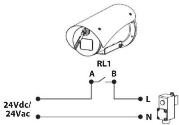
Fig. 18
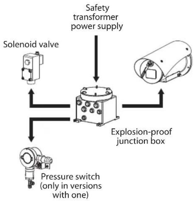
6.9.2 Connection of the pressure switch to the camera (MAXIMUS MVX)
Use the auto-powered alarm input AL1 (consult the camera manual).
Connect as in the diagram below (Fig. 19, page 15).
flowchart
graph TD
    A["Solenoid valve"] --> B["Explosion-proof junction box"]
    C["Pressure switch (only in versions with one)"] --> B
    D["Safety transformer power supply"] --> B
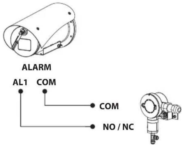
Fig. 19
Fig. 17
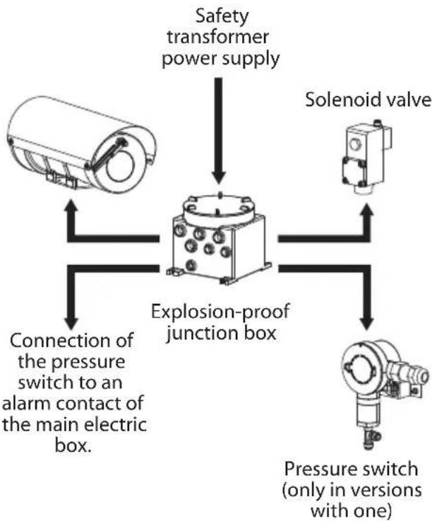
6.10 Connection to the housing (MAXIMUS MHX)

To install electrical connections between the products, use the communication boxes by null, MBX or MBA, alternatively use an explosion-proof junction box with equivalent characteristics.
flowchart
graph TD
    A["Safety transformer power supply"] --> B["Explosion-proof junction box"]
    C["Solenoid valve Scol"] --> B
    B --> D["Two cylindrical components with internal components"]
Fig. 20
flowchart
graph TD
    A["Safety transformer power supply"] --> B["Explosion-proof junction box"]
    C["Solenoid valve"] --> B
    D["Pressure switch (only in versions with one)"] --> B
    E["Connection of the pressure switch to an alarm contact of the main electric box."] --> B
6.10.1 Connection of the solenoid valve to the housing (MAXIMUS MHX)

The Washer relay in the MHX is suitable for voltages up to 30Vac or 60Vdc. Turn off one of the supply poles of the solenoid valve via the Washer relay (terminal J11) of the MHX. Consult the housing manual.
Connect as in the diagram below (Fig. 22, page 16).

The solenoid valve can be powered to 24Vac or 24Vdc with an isolated transformer or isolated converter.
The polarity of the voltage, applied to the power terminal, is irrelevant.
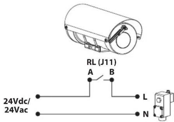
Fig. 22
6.10.2 Connection of the pressure switch to the housing (MAXIMUS MHX)
The housing does not have a prearranged alarm input.
Connection of the pressure switch to an alarm contact of the main electric box.
Fig. 21
6.11 Filling the tank

The operation of the pressure switch and the frequency of air filling depend on the amount of water in the tank. Testing is recommended to determine the amount of water in the tank appropriate for the specific application.
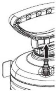
Turn the safety valve to release any residual pressure in the tank.
natural_image
Pure mechanical diagram showing a curved component with a central arrow and base, no text or symbols present.Fig. 23
With the handle (01) of the pump locked in the safe position, unscrew the pump from the container. Fill the tank (02) (10l max) Screw in the pump in the tank.
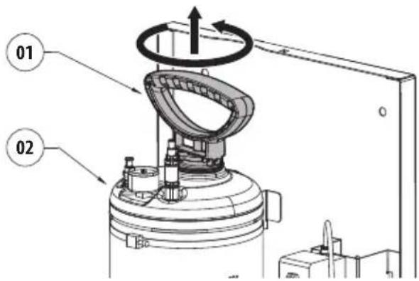
Fig. 24
6.11.1 Pressurise the tank using the manual pump
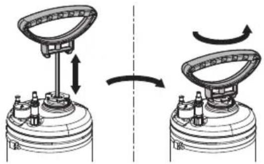
Release the handle of the pump by pressing it downwards and turning clockwise. Pressurise the tank pumping with the handle of the pump until the desired pressure is reached:
- 4bar with 20m water delivery antistatic pipe (supplied)
- 6bar with 30m water delivery antistatic pipe (available as an accessory)

If the maximum pressure (6bar) is exceeded, the safety valve activates to discharge the excess pressure.
Lock the knob of the pump in the safe position, pressing it downwards and turning anti-clockwise.
natural_image
Diagram showing a mechanical device with two views of the top base, one upward and one downward, both rotating around a central component (no text or symbols present)Fig. 25
6.11.2 Pressurise the tank using the compressed air valve

Pressurising the tank using compressed air is only permitted outside the classified zone.
Connect the compressed air pipe on the compressed air filling valve (01). Once the desired pressure is generated, remove the compressed air pipe. (Fig. 26, page 17).

Fig. 26
6.11.3 Product closure
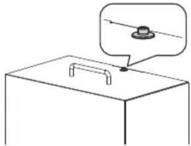
Insert the guard and tighten the safety screw.
natural_image
Simple line drawing of a table with a handle and a small inset image showing a knob (no text or symbols)Fig. 27
Screw in the two previously removed side screws.
natural_image
Diagram showing three views of a device with connectors and mounting points, no text or symbols presentFig. 28
6.12 Washer installation (MAXIMUS MPX, MAXIMUS MPX SERIES2)
Fasten the support (01) onto the PTZ body with the metal clip (02) provided.
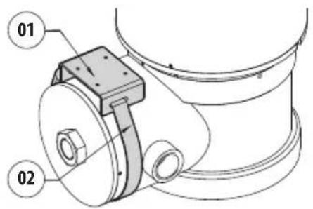
Fig. 29
Shorten the semi-rigid washer pipe (03) as needed. Unscrew the nut (04) from the joint and slide it along the pipe. Insert the end of the pipe into the spinner (05).
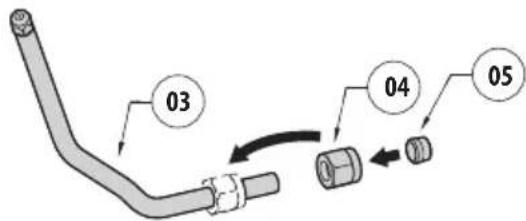
Fig. 30
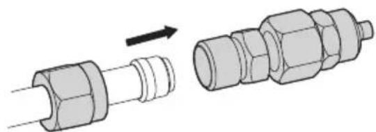
Lock the nut to the coupling.
natural_image
Diagram showing a mechanical component being inserted into a larger pipe fitting (no text or symbols present)Fig. 31
Fasten the pipe to the washer support using the bracket (06), the screws and the washers (07) provided. Connect the supply pipe (08).
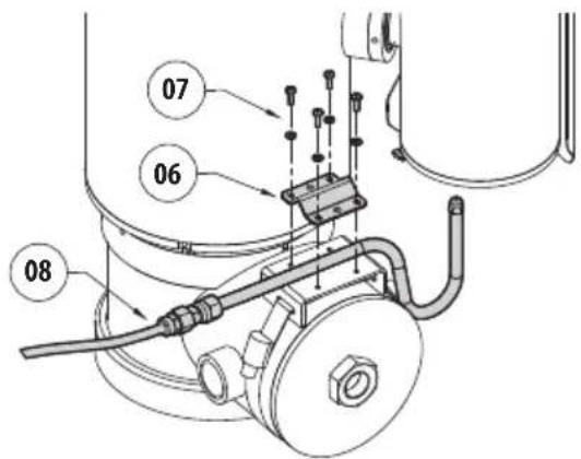
Fig. 32
To calibrate the jet, orientate the nozzle towards the window of the housing.

natural_image
Technical diagram of a mechanical device with a close-up view showing internal components (no text or symbols)Fig. 33
To start the wash system refer to the PTZ camera manual.
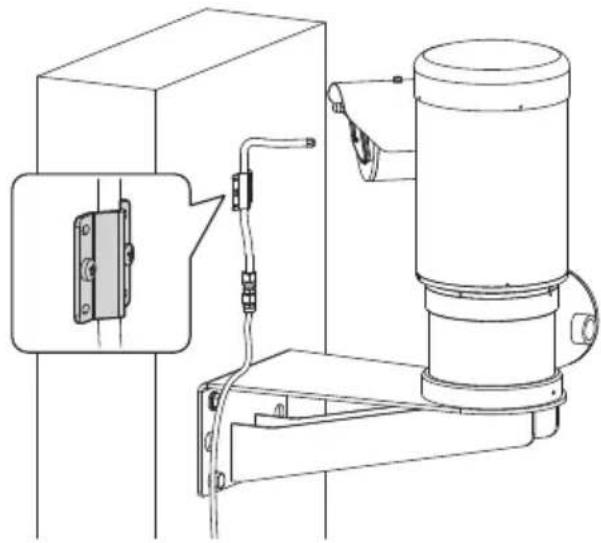
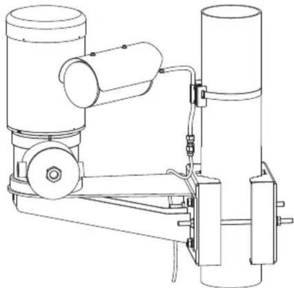
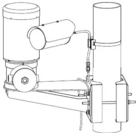
6.12.1 Installation options
natural_image
Technical line drawing of a mechanical device with attached components and a close-up inset showing a component detail (no text or symbols)Fig. 34
natural_image
Technical line drawing of a mechanical device with cylindrical components and connecting rods (no text or symbols)Fig. 35
6.13 Washer installation (MAXIMUS MVX)
Fasten the bracket (01) onto the body of the camera with the metal clip (02) provided.
Fasten the support for the delivery pipe (03) by means of the screws and washers provided (04).
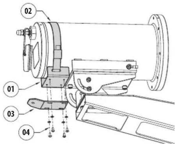
Fig. 36
Unscrew the nozzle (05) from the semi-rigid pipe. Insert the nozzle (05) through the hole in the support bracket (03) and secure with the nut and washer provided (06).
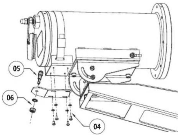
Fig. 37
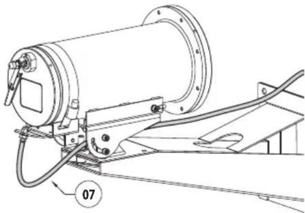
Screw the semi-rigid pipe (07) to the nozzle fixed to the bracket.
natural_image
Technical line drawing of a mechanical device with no visible text or symbolsFig. 38
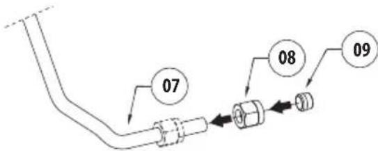
Shorten the semi-rigid washer pipe (07) as needed. Unscrew the nut (08) and slide it along the pipe. Insert the end of the pipe into the spinner (09).
flowchart
graph TD
    A["Line"] --> B["Valve"]
    B --> C["Component 07"]
    B --> D["Component 08"]
    B --> E["Component 09"]
Fig. 39
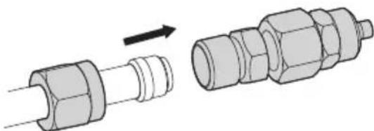
Lock the nut to the coupling.
natural_image
Diagram showing a pipe fitting being inserted into a multi-layered connector (no text or symbols present)Fig. 40
Connect the supply pipe (10).
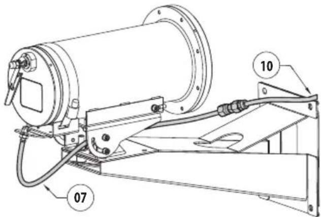
Fig. 41
To start the wash system refer to the camera manual.
6.14 Washer installation (MAXIMUS MHX)
Fasten the bracket (01) onto the body of the housing with the metal clip (02) provided.
Fasten the support for the semi-rigid pipe (03) by means of the screws and washers provided (04).
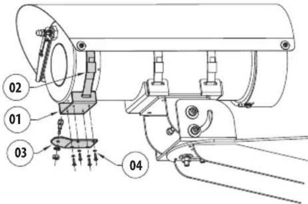
Fig. 42
Unscrew the nozzle (05) from the semi-rigid pipe. Insert the nozzle (05) through the hole in the support bracket (03) and secure with the nut and washer provided (06).
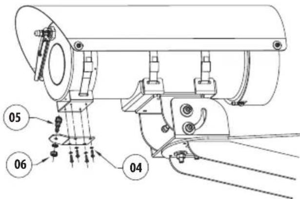
Fig. 43
Screw the semi-rigid pipe (07) to the nozzle fixed to the bracket.
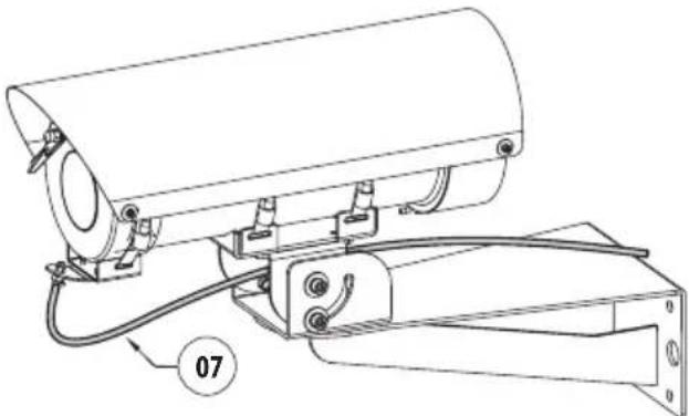
natural_image
Technical line drawing of a mechanical device with labeled component '07' (no text or symbols beyond label)Fig. 44
Shorten the semi-rigid washer pipe (07) as needed. Unscrew the nut (08) and slide it along the pipe. Insert the end of the pipe into the spinner (09).
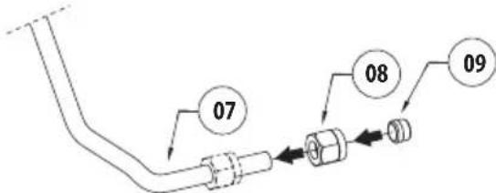
Fig. 45
Lock the nut to the coupling.
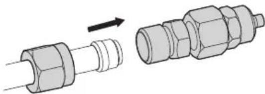
natural_image
Diagram showing a mechanical assembly process: one pipe being inserted into a housing, the other connected to a multi-colored connector (no text or symbols present)Fig. 46
Connect the supply pipe (10).
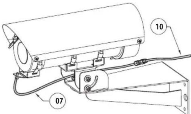
Fig. 47
To start the wash system refer to the housing manual.
7 Maintenance

Before carrying out any type of maintenance, read the "Safety rules" chapter carefully in the product manual.
Please provide the device serial number when requesting any replacement parts.
7.1 Routine maintenance
7.1.1 Filling the tank
Fill the tank with reference to the pump installation procedure (6.11 Filling the tank, page 17).
7.1.2 Inspecting the cables
The cables should not show signs of damage or wear, which could generate hazardous situations. In this case extraordinary maintenance is necessary.
8 Cleaning
8.1 Routine cleaning

The outside surface of the product must never be covered in more than 5 mm of dust.

Frequency will depend on the type of environment in which the product is used.
The device should be cleaned using a damp cloth; compressed air must not be used.
9 Information on disposal and recycling
The European Directive 2012/19/EU on Waste Electrical and Electronic Equipment (WEEE) mandates that these devices should not be disposed of in the normal flow of municipal solid waste, but they should be collected separately in order to optimize the recovery stream and recycling of the materials that they contain and to reduce the impact on human health and the environment due to the presence of potentially hazardous substances.
The symbol of the crossed out bin is marked on all products to remember this.
The waste may be delivered to appropriate collection centers, or may be delivered free of charge to the distributor where you purchased the equipment at the time of purchase of a new equivalent or without obligation to a new purchase for equipment with size smaller than 25cm (9.8in).
For more information on proper disposal of these devices, you can contact the responsible public service.
10 Technical data
10.1 Mechanical
Materials:
• External enclosure: stainless steel AISI 316L
- Antistatic water delivery pipe: antistatic polymer
Antistatic water delivery pipe (supplied):
• Length: 20m (66ft)
Schrader type compressed air filling valve
Pressure: 6bar max
Delivery:
- 20m (66ft), 4bar (with 20m water delivery antistatic pipe supplied)
- 30m (98ft), 6bar (with 30m water delivery antistatic pipe available as an accessory)
Water tank capacity: 10l (2.6gal)
Cable inputs:
- 1 x 1/2" NPT (WASEX2T4AT, WASEX2T4GOR, WASEX2T4IC, WASEX2T4IN, WASEX2T4UL)
- 2 x 1/2" NPT (WASEX2T4ATPR)
Dimensions (WxHxL): 429x697x255mm (16.9 x 27.4x10in)
Unit weight: 18kg (40lb) (WASEX2T4AT, WASEX2T4GOR, WASEX2T4IC, WASEX2T4IN, WASEX2T4UL); 20Kg (WASEX2T4ATPR)
10.2 Electrical
WASEX2T4AT, WASEX2T4GOR, WASEX2T4IC, WASEX2T4IN, WASEX2T4UL
Solenoid valve:
• Power supply: 24Vac, 50/60Hz or 24Vdc
- Consumption: 5W
WASEX2T4ATPR
Solenoid valve:
• Power supply: 24Vac, 50/60Hz or 24Vdc
- Consumption: 5W
Pressure switch: dry contact for alarm signal management
Consult the use and installation manual of the pressure switch for further information (supplied).
10.3 Environment
WASEX2T4AT, WASEX2T4GOR, WASEX2T4IC, WASEX2T4IN, WASEX2T4UL
For indoors and outdoors installation
Operating temperature of solenoid valve: from -40^ ( -40^ ) up to +60^ ( 140^ )
Operating temperature of device: depending on the solidification temperature of the liquid
Relative humidity: from 5% up to 95%
WASEX2T4ATPR
For indoors and outdoors installation
Operating temperature of solenoid valve: from -40^ ( -40^ ) up to +60^ ( 140^ )
Pressure switch working temperature: from -40^ (-40°F) up to +80^ (+176°F)
Operating temperature of device: depending on the solidification temperature of the liquid
Relative humidity: from 5% up to 95%
10.4 Certifications - Marine applications
WASEX2T4AT, WASEX2T4GOR, WASEX2T4IN
Lloyd's Register Marine Type Approval certification:
- Test Specification Number 1 (ENV1, ENV2, ENV3, ENV5)
Salty fog resistance: EN60068-2-52
Tested at 70°C (158°F) for 16 hours in compliance with EN60068-2-2
11 Technical drawings

The indicated measurements are expressed in millimetres.

The number of holes for cable passage depends on the model.
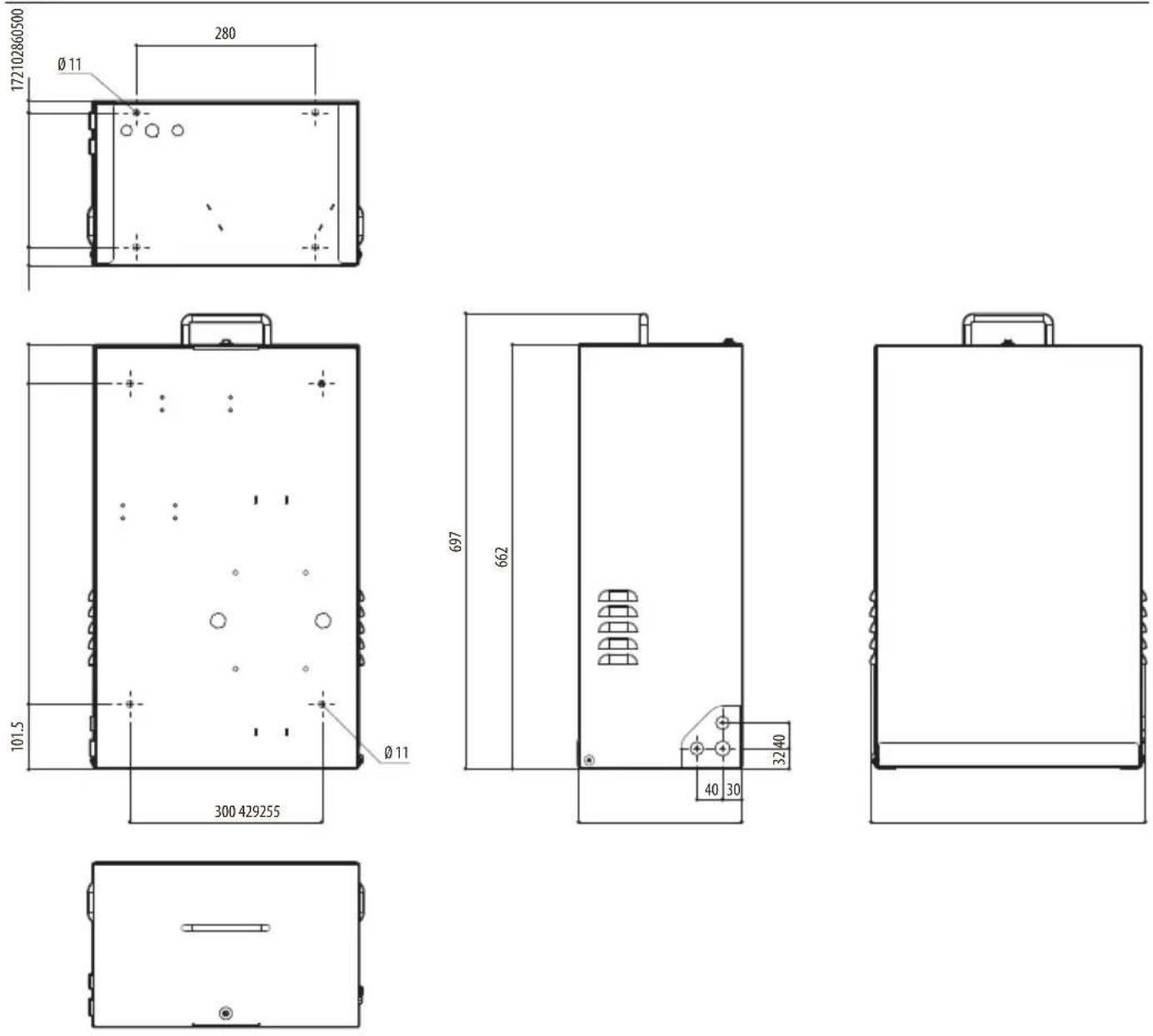
Fig. 48 WASEX.
WASEX
natural_image
Line drawing of a rectangular industrial enclosure with ventilation slots and a handle (no text or symbols)Sommario
Fig. 1

natural_image
Technical line drawing of a mechanical device with numbered components and an arrow pointing to a component (no text or symbols present)Fig. 2
natural_image
Diagram showing three views of a battery with connectors and a side panel, no text or symbols presentFig. 3
Fig. 4
Fig. 5
natural_image
Mechanical assembly diagram showing a shaft and housing with a directional arrow (no text or symbols)Fig. 6
natural_image
Diagram showing a rotating mechanical component with directional arrows, no text or symbols presentFig. 7
natural_image
Technical line drawing of a mechanical component with mounting holes and directional arrows indicating force or movement (no text or symbols)Fig. 8
natural_image
Technical line drawing of a mechanical assembly with mounting bracket and cylindrical component (no text or symbols)Fig. 9 WASEX+NXCOL.
natural_image
Technical line drawing of a mechanical assembly with mounting brackets and a separate housing (no text or symbols)Fig. 10 WASEX+NXCW.
Fig. 11
6.5 Messa a terra
6.5.1 Collegamento equipotenziale di terra
natural_image
Technical line drawing showing a component with a cable and circular features, no text or symbols presentFig. 12

natural_image
Technical line drawing of a mechanical assembly with no visible text or symbolsFig. 23
natural_image
Diagram showing a mechanical device with two views of the top base, illustrating a transformation or assembly process (no text or symbols present)Fig. 25
natural_image
Simple line drawing of a table with a handle and a small circular object on top (no text or symbols)Fig. 27
natural_image
Diagram showing three views of a battery with connectors and mounting points, no text or symbols presentFig. 28
natural_image
Diagram showing two mechanical components with a directional arrow indicating assembly (no text or symbols present)Fig. 31
Fig. 32
natural_image
Technical diagram of a mechanical device with labeled components and an inset showing a close-up of the internal structure (no text or symbols present)Fig. 33
natural_image
Technical line drawing of a mechanical device with attached components and a close-up inset showing a component detail (no text or symbols present)Fig. 34
natural_image
Technical line drawing of a mechanical device with cylindrical components and connecting rods (no text or symbols)Fig. 35
Fig. 37
natural_image
Technical line drawing of a mechanical device with labeled component '07' (no text or symbols beyond label)Fig. 38
natural_image
Diagram showing a mechanical component being inserted into a larger cylindrical assembly (no text or symbols present)Fig. 40
Fig. 41
natural_image
Technical line drawing of a mechanical device with labeled component '07' (no text or symbols beyond label)Fig. 44
natural_image
Diagram showing a mechanical assembly process: one pipe being inserted into a housing, the other being assembled (no text or symbols present)Fig. 46
Fig. 47
natural_image
Line drawing of a rectangular industrial enclosure with ventilation slots and a handle (no text or symbols)Sommaire
6 Installation....10
Fig. 1

natural_image
Technical line drawing of a mechanical device with numbered components and an arrow pointing to a component (no text or symbols present)Fig. 2
natural_image
Diagram showing three views of a battery with connectors and a close-up of its side, no text or symbols present.Fig. 3
Fig. 4
Fig. 5
natural_image
Mechanical assembly diagram showing a shaft and housing with an arrow indicating direction (no text or symbols)Fig. 6
natural_image
Diagram showing two rotating components with directional arrows, no text or symbols presentFig. 7
natural_image
Technical line drawing of a mechanical component with mounting holes and directional arrows indicating force or movement (no text or symbols)Fig. 8
natural_image
Technical line drawing of a mechanical assembly with mounting bracket and cylindrical component (no text or symbols)Fig. 9 WASEX+NXCOL.
natural_image
Technical line drawing of a mechanical assembly with mounting brackets and a separate housing (no text or symbols)Fig. 10 WASEX+NXCW.
Fig. 11
6.5 Mise à terre
natural_image
Technical line drawing showing two views of a device with circular components and a cable (no text or symbols)Fig. 12

natural_image
Technical line drawing of a mechanical assembly with a central component and concentric rings (no text or symbols)Fig. 23
Fig. 24
natural_image
Diagram showing a mechanical device with two views of the top base, illustrating a transformation or assembly process (no text or symbols present)Fig. 25
natural_image
Technical line drawing of a mechanical device with labeled component (01), no readable text or symbols beyond labelFig. 26
natural_image
Simple line drawing of a table with a handle and a small circular object on top (no text or symbols)Fig. 27
natural_image
Diagram showing a battery connected to a wall-mounted cable with two side views (no text or symbols present)Fig. 28
6.12 Installation du lave-vitre (MAXIMUS MPX, MAXIMUS MPX SERIES2)
natural_image
Diagram showing a pipe fitting being inserted into a multi-layered connector (no text or symbols present)Fig. 31
Fig. 32
natural_image
Technical diagram of a mechanical device with a close-up view showing internal components (no text or symbols)Fig. 33
natural_image
Technical line drawing of a mechanical device with attached components and a close-up inset showing a component detail (no text or symbols)Fig. 34
natural_image
Technical line drawing of a mechanical device with cylindrical components and connecting rods (no text or symbols)Fig. 35
Fig. 37
natural_image
Technical line drawing of a mechanical device with no visible text or symbolsFig. 38
natural_image
Diagram showing a pipe fitting being inserted into a multi-port connector (no text or symbols present)Fig. 40
Fig. 41
natural_image
Technical line drawing of a mechanical device with labeled component '07' (no text or symbols beyond label)Fig. 44
natural_image
Diagram showing a pipe fitting being inserted into a connected connector (no text or symbols present)Fig. 46
Fig. 47
Dimensions (WxHxL): 429x697x255mm
Poids net: 18kg (WASEX2T4AT, WASEX2T4GOR, WASEX2T4IC, WASEX2T4IN, WASEX2T4UL); 20Kg (WASEX2T4ATPR)
10.2 Électrique
WASEX2T4AT, WASEX2T4GOR, WASEX2T4IC, WASEX2T4IN, WASEX2T4UL
Électrovanne:
• Alimentation: 24Vac, 50/60Hz ou 24Vdc
• Consommation: 5W
WASEX2T4ATPR
Électrovanne:
• Alimentation: 24Vac, 50/60Hz ou 24Vdc
- Consommation: 5W
10.4 Certifications - Applications marines
WASEX2T4AT, WASEX2T4GOR, WASEX2T4IN
Certification Lloyd's Register Marine Type Approval:
- Test Specification Number 1 (ENV1, ENV2, ENV3, ENV5)
natural_image
Line drawing of a rectangular industrial enclosure with ventilation slots and a handle (no text or symbols)Inhaltsverzeichnis
1 Allgemeines 5
6 Installation....10
Abb. 1

natural_image
Technical line drawing of a mechanical device with numbered components and an arrow pointing to a component (no text or symbols present)Abb. 2
natural_image
Diagram showing three views of a battery with connectors and mounting points, no text or symbols presentAbb. 3
Abb. 4
Abb. 5
natural_image
Mechanical assembly diagram showing a shaft and housing with an arrow indicating direction (no text or symbols)Abb. 6
natural_image
Diagram showing two rotating components with directional arrows, no text or symbols presentAbb. 7
natural_image
Technical line drawing of a mechanical housing component with mounting holes and arrows indicating force or movement (no text or symbols)Abb. 8
natural_image
Technical line drawing of a mechanical assembly with mounting bracket and cylindrical component (no text or symbols)Abb. 9 WASEX+NXCOL.
natural_image
Technical line drawing of a mechanical assembly with mounting bracket and housing (no text or symbols)Abb. 10 WASEX+NXCW.
Abb. 11
6.5 Erdung
natural_image
Technical line drawing showing two views of a device with circular components and a cable (no text or symbols)Abb. 12

natural_image
Technical line drawing of a mechanical assembly with no visible text or symbolsAbb. 23
natural_image
Diagram showing a mechanical device with two views of the top base, illustrating a transformation or assembly process (no text or symbols present)Abb. 25
natural_image
Simple line drawing of a table with a handle and a small inset showing a circular object (no text or symbols)Abb. 27
natural_image
Technical line drawing of a mechanical assembly with three views showing different components (no text or symbols)Abb. 28
6.12 Installation der Scheibenwascheinheit (MAXIMUS MPX, MAXIMUS MPX SERIES2)
natural_image
Diagram showing a mechanical component being inserted into a larger cylindrical assembly (no text or symbols present)Abb. 31
Abb. 32
natural_image
Technical line drawing of a mechanical assembly with no visible text or symbolsAbb. 33
natural_image
Technical line drawing of a mechanical device with attached components and a close-up inset showing a component detail (no text or symbols)Abb. 34
natural_image
Technical line drawing of a mechanical device with cylindrical components and connecting rods (no text or symbols)Abb. 35
Abb. 37
natural_image
Technical line drawing of a mechanical device with no visible text or symbolsAbb. 38
natural_image
Diagram showing two mechanical components with a directional arrow indicating assembly (no text or symbols present)Abb. 40
Abb. 41
natural_image
Technical line drawing of a mechanical device with labeled component '07' (no text or symbols beyond label)Abb. 44
natural_image
Diagram showing a mechanical assembly process: one pipe being inserted into a housing, the other being assembled (no text or symbols present)Abb. 46
Abb. 47
natural_image
Line drawing of a rectangular industrial enclosure with ventilation slots and a handle (no text or symbols)Рис. 1

natural_image
Technical line drawing of a mechanical device with numbered components and an arrow pointing to a component (no text or symbols present)Рис. 2
natural_image
Technical line drawing of a mechanical assembly with two views showing internal components (no text or symbols)Рис. 3
Рис. 4
Рис. 5
natural_image
Mechanical assembly diagram showing a shaft and housing with a directional arrow (no text or symbols)Рис. 6
natural_image
Diagram showing two rotating components with directional arrows, no text or symbols presentРис. 7
natural_image
Isometric technical drawing of a mechanical housing component with mounting holes and arrows indicating force or movement (no text or symbols)Рис. 8
natural_image
Technical line drawing of a mechanical assembly with mounting bracket and cylindrical component (no text or symbols)Рис. 9 WASEX+NXCOL.
natural_image
Technical line drawing of a mechanical assembly with mounting bracket and housing (no text or symbols)Рис. 10 WASEX+NXCW.
Рис. 11
natural_image
Technical line drawing showing a pipe connection to a panel with circular holes and a base, alongside a separate view of a wall-mounted component (no text or symbols)Рис. 12

natural_image
Technical line drawing of a mechanical assembly with no visible text or symbolsРис. 23
Рис. 24
natural_image
Diagram showing a mechanical device with two views of the top base, illustrating a transformation or assembly process (no text or symbols present)Рис. 25
natural_image
Simple line drawing of a table with a handle and a small circular object on top (no text or symbols)Рис. 27
natural_image
Diagram showing a battery connected to three separate views of a mechanical component (no text or symbols present)Рис. 28
natural_image
Diagram showing two mechanical components with a directional arrow indicating assembly (no text or symbols present)Рис. 31
Рис. 32
natural_image
Technical line drawing of a mechanical assembly with no visible text or symbolsРис. 33
natural_image
Technical line drawing of a mechanical device with attached components and a close-up inset showing a component detail (no text or symbols)Рис. 34
natural_image
Technical line drawing of a mechanical device with cylindrical components and connecting rods (no text or symbols)Рис. 35
Рис. 37
natural_image
Technical line drawing of a mechanical device with no visible text or symbolsРис. 38
natural_image
Diagram showing a mechanical assembly process: one pipe fitting is being processed, the other is assembled (no text or symbols present)Рис. 40
Рис. 41
natural_image
Technical line drawing of a mechanical device with labeled component '07' (no text or symbols beyond label)Рис. 44
natural_image
Diagram showing two mechanical components with a directional arrow indicating assembly (no text or symbols present)Рис. 46
Рис. 47
natural_image
Line drawing of a rectangular industrial enclosure with ventilation slots and a handle (no text or symbols)Sumário
Fig. 1

natural_image
Technical line drawing of a mechanical device with numbered components and an arrow pointing to a component (no text or symbols present)Fig. 2
natural_image
Diagram showing three views of a battery with connectors and a central casing, no text or symbols present.Fig. 3
Desparafuse o parafuso de segurança (04) e levante o cárter (05).
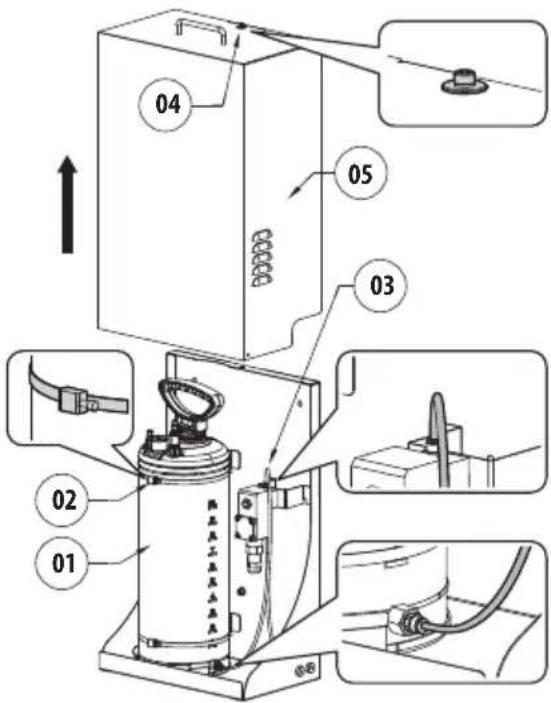
Fig. 4
6.2 Furação da tela
Fig. 5
natural_image
Mechanical assembly diagram showing a shaft and housing with a directional arrow (no text or symbols)Fig. 6
natural_image
Diagram showing two mechanical components with rotational arrows, no text or symbols presentFig. 7
natural_image
Isometric technical drawing of a mechanical component with mounting holes and directional arrows (no text or symbols)Fig. 8
natural_image
Technical line drawing of a mechanical assembly with mounting bracket and cylindrical component (no text or symbols)Fig. 9 WASEX+NXCOL.
natural_image
Technical line drawing of a mechanical assembly with mounting brackets and a separate housing (no text or symbols)Fig. 10 WASEX+NXCW.
Fig. 11
6.5 Aterramento
natural_image
Technical line drawing showing two views of a mechanical or electrical component with circular holes and a cable (no text or symbols)Fig. 12

natural_image
Pure mechanical diagram showing a curved structure with a central component and an arrow indicating direction (no text or symbols)Fig. 23
Fig. 24
natural_image
Diagram showing a mechanical device with two views of the top base, one being lifted and the other rotating (no text or symbols present)Fig. 25
natural_image
Technical line drawing of a mechanical device with labeled component (01), no readable text or symbols beyond labelFig. 26
natural_image
Simple line drawing of a table with a handle and a small circular object on top (no text or symbols)Fig. 27
natural_image
Diagram showing three views of a battery with connectors and mounting points, no text or symbols presentFig. 28
natural_image
Diagram showing two mechanical components with a directional arrow indicating assembly (no text or symbols present)Fig. 31
Fig. 32
natural_image
Technical diagram of a mechanical device with a close-up view showing internal components (no text or symbols)Fig. 33
natural_image
Technical line drawing of a mechanical device with attached components and a close-up inset showing a component detail (no text or symbols)Fig. 34
natural_image
Technical line drawing of a mechanical device with cylindrical components and connecting rods (no text or symbols)Fig. 35
Fig. 37
natural_image
Technical line drawing of a mechanical device with no visible text or symbolsFig. 38
natural_image
Diagram showing a mechanical component being inserted into a larger cylindrical assembly (no text or symbols present)Fig. 40
Fig. 41
natural_image
Technical line drawing of a mechanical device with labeled component '07' (no text or symbols beyond label)Fig. 44
natural_image
Diagram showing two mechanical components with a directional arrow indicating assembly (no text or symbols present)Fig. 46
Fig. 47

Headquarters Italy VIDEOTEC s.r.l.
Via Friuli, 6 - I-36015 Schio (VI) - Italy
Tel. +39 0445 697411 - Fax +39 0445 697414
Email: info@videotec.com
www.videotec.com
- Contents
- About this manual....5
- Notes on copyright and information on trademarks....5
- Safety rules ....5
- Product description and type designation....7
- Preparing the product for use....10
- Installation....10
- Maintenance....22
- Cleaning 22
- Information on disposal and recycling 22
- Technical data....23
- Technical drawings....24
- About this manual
- Typographical conventions
- Notes on copyright and information on trademarks
- Safety rules
- DANGER!
- High level hazard.
- CAUTION!
- Medium level hazard.
- INFO
- Product description and type designation
- Product overview
- Product marking label
- Model identification
- Preparing the product for use
- Unpacking
- Contents
- Safely disposing of packaging material
- Installation
- Product opening
- Frame perforation
- Assembly of the seal rings
- Installation options
- Wall or floor fastening
- Fixing with corner adaptor module or pole
- Delivery pipe connection
- Ground connection
- Earthing equipotential connection
- Connection of the solenoid valve
- Pressure switch connection
- Connection to PTZ (MAXIMUS MPX, MAXIMUS MPX SERIES2)
- Connection of the solenoid valve to the PTZ (MAXIMUS MPX, MAXIMUS MPX SERIES2)
- Connection of the pressure switch to the PTZ (MAXIMUS MPX, MAXIMUS MPX SERIES2)
- Connection to the camera (MAXIMUS MVX)
- Connection of the solenoid valve to the camera (MAXIMUS MVX)
- Connection of the pressure switch to the camera (MAXIMUS MVX)
- Connection to the housing (MAXIMUS MHX)
- Connection of the solenoid valve to the housing (MAXIMUS MHX)
- Connection of the pressure switch to the housing (MAXIMUS MHX)
- Filling the tank
- Pressurise the tank using the manual pump
- Pressurise the tank using the compressed air valve
- Product closure
- Washer installation (MAXIMUS MPX, MAXIMUS MPX SERIES2)
- Washer installation (MAXIMUS MVX)
- Washer installation (MAXIMUS MHX)
- Maintenance
- Routine maintenance
- Filling the tank
- Inspecting the cables
- Cleaning
- Routine cleaning
- Information on disposal and recycling
- Technical data
- Mechanical
- Materials:
- Delivery:
- Cable inputs:
- Electrical
- WASEX2T4AT, WASEX2T4GOR, WASEX2T4IC, WASEX2T4IN, WASEX2T4UL
- Solenoid valve:
- WASEX2T4ATPR
- Environment
- Certifications - Marine applications
- WASEX2T4AT, WASEX2T4GOR, WASEX2T4IN
- Technical drawings
- WASEX
- Sommario
- Messa a terra
- Collegamento equipotenziale di terra
- Sommaire
- Mise à terre
- Installation du lave-vitre (MAXIMUS MPX, MAXIMUS MPX SERIES2)
- Électrique
- Électrovanne:
- Certifications - Applications marines
- Inhaltsverzeichnis
- Allgemeines 5
- Erdung
- Abb. 23
- Abb. 25
- Installation der Scheibenwascheinheit (MAXIMUS MPX, MAXIMUS MPX SERIES2)
- Рис. 23
- Рис. 24
- Рис. 25
- Sumário
- Furação da tela
- Aterramento
Brand : Videotec
Model : WASEX
Category : Washing machine