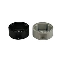
UEAW - Electronic device accessory Videotec - Free user manual and instructions
Find the device manual for free UEAW Videotec in PDF.


| Product type | Mounting backplate |
| Brand | Videotec |
| Model | UEAW |
| Construction | Stainless steel AISI 316L |
| Compatibility | Mounts UEBP, UEBW (ULISSE EVO) and NVX, NTX cameras |
| Dimensions (L x W x H) | 200 x 154 x 85 mm |
| Passage diameter | 70 mm |
| Mounting diameter | 114 mm |
| Estimated weight | Approximately 0.5 kg |
| Recommended tightening torque | 10.5 Nm (±0.25 Nm) |
| Mounting | 4 holes for Ø8 mm screws; 3 or 4 threaded holes depending on support |
| Package contents | Backplate, screws, instruction manual |
| Operating instructions | User manual included (25 pages) |
| Installation | By qualified personnel; use wall plugs adapted to the support |
| Thread-locking product | Loctite 243® recommended |
| Disposal of packaging | Recyclable materials; follow local regulations |
| Warranty | UNAPPROVED MODIFICATIONS VOID WARRANTY |
Frequently Asked Questions - UEAW Videotec
User questions about UEAW Videotec
0 question about this device. Answer the ones you know or ask your own.
Ask a new question about this device
Download the instructions for your Electronic device accessory in PDF format for free! Find your manual UEAW - Videotec and take your electronic device back in hand. On this page are published all the documents necessary for the use of your device. UEAW by Videotec.
USER MANUAL UEAW Videotec
natural_image
3D technical drawing of a mechanical bracket with mounting holes and a central circular hole (no text or symbols)EN English - Instruction manual
IT Italiano - Manuale di istruzioni
FR Français - Manuel d'instructions
DE Deutsch - Bedienungsanleitung
RU Русский - Руководство по эксплуатации
1 About this manual
Read all the documentation supplied carefully before installing and using this unit. Keep the manual in a convenient place for future reference.
1.1 Typographical conventions

CAUTION!
Medium level hazard.
This operation is very important for the system to function properly. Please read the procedure described very carefully and carry it out as instructed.

INFO
Description of system specifications.
We recommend reading this part carefully in order to understand the subsequent stages.
2 Notes on copyright and information on trademarks
The mentioned names of products or companies are trademarks or registered trademarks.
3 Safety rules

CAUTION! Device installation and maintaining must be performed by specialist technical staff only.
- The manufacturer declines all responsibility for any damage caused by an improper use of the appliances mentioned in this manual.
Furthermore, the manufacturer reserves the right to modify its contents without any prior notice. The documentation contained in this manual has been collected and verified with great care. The manufacturer, however, cannot take any liability for its use. The same thing can be said for any person or company involved in the creation and production of this manual. - Before starting any operation, make sure the power supply is disconnected.
- Use only original spare parts. Non-original spare parts could cause fire, electrical discharge or other hazards.
4 Identification
4.1 Product description and type designation
Counter-plate in stainless steel AISI 316L. For UEBP and UEBW (ULISSE EVO) and compatible with NVX, NTX cameras.
5 Preparing the product for use

Any change that is not expressly approved by the manufacturer will invalidate the guarantee.
5.1 Unpacking
When the product is delivered, make sure that the package is intact and that there are no signs that it has been dropped or scratched.
If there are obvious signs of damage, contact the supplier immediately.
When returning a faulty product we recommend using the original packaging for shipping.
Keep the packaging in case you need to send the product for repairs.
5.2 Safely disposing of packaging material
The packaging material can all be recycled. The installer technician will be responsible for separating the material for disposal, and in any case for compliance with the legislation in force where the device is to be used.
5.3 Contents
Check the contents to make sure they correspond with the list of materials as below:
- Counter-plate
- Bolts and screws
- Instruction manual
6 Installation
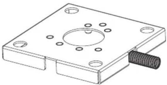
The counter-plate can be used for railing, wall or ceiling assembly, also for channel applications.
natural_image
Technical line drawing of a mechanical bracket with mounting holes and a threaded end (no text or symbols)Fig. 1

Take special care when attaching and fastening down the apparatus. If it is to be attached to a concrete surface you must use dowel pins with a traction torque rating of at least 300dN each. For a metal surface use screws with a diameter of at least 8mm and of an appropriate length. The fastening system must be capable of supporting at least 4 times the weight of the entire equipment (pan & tilt, lens, camera, supports and adapters).
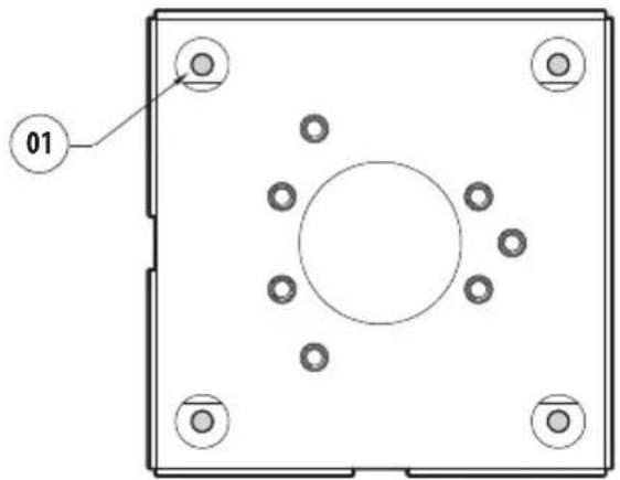
Fasten the counter-plate to the ceiling or the railing using the 4 holes (01). Use the screws with a diameter equal to 8mm.
natural_image
Technical drawing of a square mechanical component with bolt holes and a central circular feature (no text or symbols)Fig. 2
Fasten the UEBP support (ULISSE EVO) to the counter-plate using the screws and washers supplied (02), using the 3 threaded holes (03) (Fig. 3 Fastening for UEBP (ULISSE EVO), page 3).
Make sure the thread are free of dirt and debris.

Put some thread-locker into the holes for screws (Loctite 243®).

Pay attention to the fixing. Tightening torque: 10.5Nm (±0.25Nm).
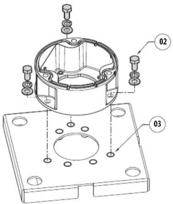
Fig. 3 Fastening for UEBP (ULISSE EVO)
Fasten the UEBW support (ULISSE EVO) or NVX, NTX unit to the counter-plate using the screws and washers supplied (04), using the 4 threaded holes (05) (Fig. 4 Fastening for UEBW (ULISSE EVO), page 3 and Fig. 5 Fastening for NVX, NTX, page 3).
Make sure the thread are free of dirt and debris.

Put some thread-locker into the holes for screws (Loctite 243 ^® ).

Pay attention to the fixing. Tightening torque: 10.5Nm (±0.25Nm).
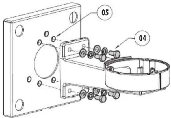
Fig. 4 Fastening for UEBW (ULISSE EVO)
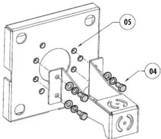
Fig. 5 Fastening for NVX, NTX
7 Technical data
7.1 Mechanical
Bracket for UEBW, UEBP (ULISSE EVO) and for NVX, NTX cameras
AISI 316L stainless steel construction
Dimensions: 200x200x25mm (7.9x7.9x0.98in)
Unit weight: 1.38kg (3.04lb)
8 Technical drawings

The indicated measurements are expressed in millimetres.
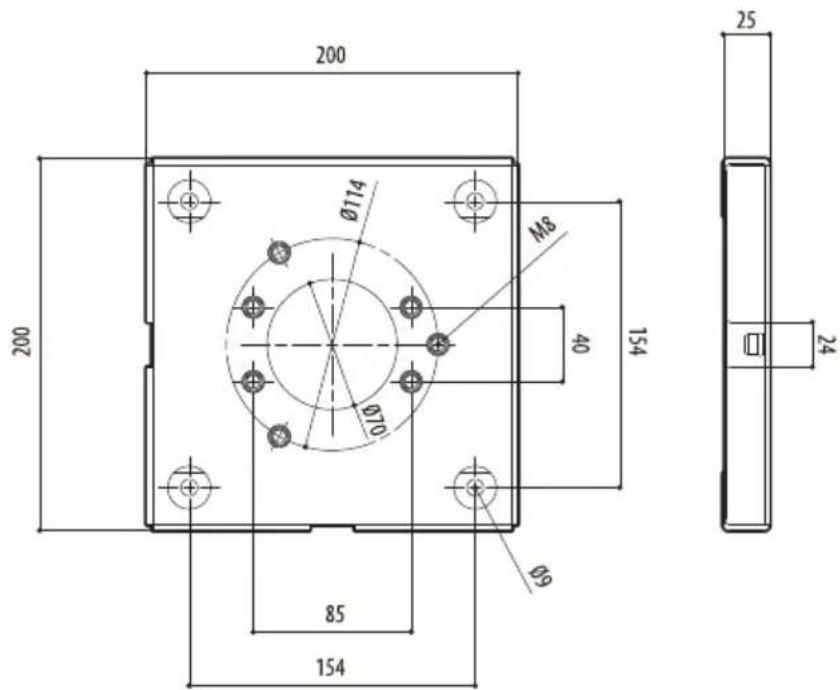
Fig. 6 UEAW.
natural_image
Technical line drawing of a mechanical bracket with mounting holes and a threaded bolt (no text or symbols)Fig. 1

natural_image
Technical diagram of a square mechanical component with bolt holes and a central circular feature (no text or symbols)Fig. 2
natural_image
Technical line drawing of a mechanical bracket with mounting holes and a threaded bolt (no text or symbols)Fig. 1

natural_image
Technical diagram of a square mechanical component with bolt holes and a central circular feature (no text or symbols)Fig. 2
Dimensions: 200x200x25mm
Poids net: 1.38kg
8 Dessins techniques

natural_image
Technical line drawing of a mechanical bracket with mounting holes and a threaded bolt (no text or symbols)Abb. 1

natural_image
Technical diagram of a square mechanical component with bolt holes and a central circular feature (no text or symbols)Abb. 2
natural_image
Technical line drawing of a mechanical bracket with mounting holes and a threaded bolt (no text or symbols)Рис. 1

natural_image
Technical diagram of a square mechanical component with bolt holes and a central circular feature (no text or symbols)Рис. 2

Headquarters Italy VIDEOTEC s.r.l.
Via Friuli, 6 - I-36015 Schio (VI) - Italy
Tel. +39 0445 697411 - Fax +39 0445 697414
Email: info@videotec.com
www.videotec.com
- About this manual
- Typographical conventions
- CAUTION!
- INFO
- Notes on copyright and information on trademarks
- Safety rules
- Identification
- Product description and type designation
- Preparing the product for use
- Unpacking
- Safely disposing of packaging material
- Contents
- Installation
- Technical data
- Mechanical
- Technical drawings
- Dessins techniques
Brand : Videotec
Model : UEAW
Category : Electronic device accessory