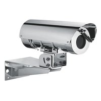
Maximus MHX - Surveillance Camera Videotec - Free user manual and instructions
Find the device manual for free Maximus MHX Videotec in PDF.


| Product Type | Explosion-proof surveillance housing |
| Brand | Videotec |
| Model | Maximus MHX |
| Material | Electropolished AISI 316L stainless steel |
| Dimensions (L x W x H) | 422 x 165 x 245 mm |
| Net weight | 16.5 kg |
| Power supply | 230 Vac, 120 Vac, 24 Vac or 12 Vdc depending on model |
| Maximum consumption | 80 W |
| Protection rating | IP66 / IP67 |
| Temperature range | -40 °C to +60 °C |
| Explosion-proof certifications | ATEX II 2G Ex db IIC T6 Gb / II 2D Ex tb IIIC T85°C Db, IECEx, EAC Ex, KCs, UK Ex |
| Window type | Tempered glass (MHX) or Germanium with anti-scratch coating (MHXT) |
| Useful window diameter | 75 mm (MHX) / 56 mm (MHXT) |
| Cable entries | 2 x 3/4" NPT or M25 |
| Compatible cameras | Max power 13 W, max dimensions 80x82x245 mm, minimum distance 10 mm from the window |
| Serial communication | RS-485 half-duplex, Pelco D or Videotec Macro protocols |
| Integrated functions | Heating, windshield wiper (option), washing system (option), day/night output |
| Installation options | Mounting on parapet, bracket, pole or angular module |
| Maintenance and cleaning | Clean with damp cloth, do not use compressed air |
| Safety | Do not open in explosive atmosphere, mandatory grounding, use original spare parts |
| Country of origin | Italy (Videotec s.r.l.) |
Frequently Asked Questions - Maximus MHX Videotec
User questions about Maximus MHX Videotec
0 question about this device. Answer the ones you know or ask your own.
Ask a new question about this device
Download the instructions for your Surveillance Camera in PDF format for free! Find your manual Maximus MHX - Videotec and take your electronic device back in hand. On this page are published all the documents necessary for the use of your device. Maximus MHX by Videotec.
USER MANUAL Maximus MHX Videotec
natural_image
Technical line drawing of two cylindrical electronic components with mounting brackets and a central fan-like feature (no text or symbols)EN English - Instruction manual
natural_image
Technical line drawing of two cylindrical electronic components with mounting brackets and a central hub (no text or symbols)Contents
1 About this manual....7
1.1 Typographical conventions....7
2 Notes on copyright and information on trademarks....7
3 Safety rules 7
4 Product description and type designation....10
4.1 Product overview .... 10
4.2 Range of use....10
4.3 Specific use conditions 10
4.4 Gas Group, Dust Group and Temperatures....10
4.5 Characteristics of installable devices....11
4.6 Cable entry 11
4.7 Product marking....12
4.8 Model identification....13
4.8.1 Housing for Day/Night camera 13
4.8.2 Housing for thermal camera....13
5 Preparing the product for use....14
5.1 Unpacking....14
5.2 Contents 14
5.3 Safely disposing of packaging material....14
6 Installation....14
6.1 Installation options....14
6.1.1 Parapet mounting 14
6.1.2 Bracket mounting....15
6.1.3 Fixing the unit to the pole mount adapter or corner mount adapter ....16
6.1.3.1 Fixing with pole mount 16
6.1.3.2 Fixing with corner adapter 16
6.2 Sunshield mounting 17
6.3 Fastening of the wiper blade....17
6.4 Adjusting the protection grid 17
6.5 Housing opening....18
6.6 Connector board description....19
6.6.1 Description of the connectors board for MHX without wiper....19
6.6.2 Description of the connectors board for MHX with wiper and for MHXT 19
6.6.3 Description of the CPU board for MHX with wiper and for MHXT....20
6.7 Earth ground connection....21
6.7.1 Earthing equipotential connection 21
6.7.2 Connection of the safety earthing....21
6.8 Connecting the power supply 21
6.8.1 Connection of the power supply line in 24Vac and 12Vdc for MHX without wiper ....21
6.8.2 Connection of the power supply line in 120Vac and 230Vac for MHX without wiper 22
6.8.3 Connection of the power supply line in 24Vac, 120Vac, 230Vac and 12Vdc for MHX with wiper and for MHXT.. 23
6.9 How to install the camera/lens 23
6.10 Connection of the camera to the power supply 24
6.10.1 Connection of the camera power supply in 24Vac and 12Vdc for MHX without wiper....24
6.10.2 Connection of the camera power supply in 120Vac and 230Vac for MHX without wiper....24
6.10.3 Connection of the camera power supply in 24Vac, 120Vac, 230Vac and 12Vdc for MHX with wiper and for MHXT 25
6.11 Camera with analogue video output....25
6.12 Optical fiber connection....26
6.13 IP camera with digital data transmission 27
6.14 Connection of the IP camera's RS-485 output 27
6.15 Serial line connection....28
6.15.1 Special controls 29
6.16 Enabling the wiper 30
6.16.1 Enable from the remote button ....30
6.16.2 Enable from the keyboard....30
6.17 Enabling the washer (Washer)....30
6.18 Enable an external illuminator from the day/night camera output....31
6.19 Housing closure 32
7 Switching on 32
8 Maintenance....33
8.1 Routine maintenance 33
8.1.1 Inspecting the cables 33
8.1.2 Replacing the gasket....33
8.2 Extraordinary maintenance 33
8.2.1 Fuses replacement....33
9 Cleaning 34
9.1 Cleaning the glass window....34
9.2 Cleaning the germanium window....34
9.3 Cleaning the product....34
10 Information on disposal and recycling 34
11 Troubleshooting....35
12 Technical data....35
12.1 MAXIMUS MHX....35
12.1.1 General 35
12.1.2 Mechanical....35
12.1.3 Electrical....35
12.1.4 Serial communications....36
12.1.5 I/O 36
12.1.6 Cameras....36
12.1.7 Environment....36
12.1.8 Certifications....36
12.1.9 Certifications - Explosion-proof applications....36
12.2 MAXIMUS MHXT....37
12.2.1 General....37
12.2.2 Mechanical 37
12.2.3 Housing's window 37
12.2.4 Electrical 37
12.2.5 Serial communications....37
12.2.6 Cameras....37
12.2.7 Environment 37
12.2.8 Certifications 37
12.2.9 Certifications - Explosion-proof applications 37
13 Technical drawings....38
1 About this manual
Read all the documentation supplied carefully before installing and using this product. Keep the manual in a convenient place for future reference.
1.1 Typographical conventions

DANGER!
Explosion hazard.
Read carefully to avoid danger of explosion.

DANGER!
High level hazard.
Risk of electric shock. Disconnect the power supply before proceeding with any operation, unless indicated otherwise.

CAUTION!
Medium level hazard.
This operation is very important for the system to function properly. Please read the procedure described very carefully and carry it out as instructed.

INFO
Description of system specifications.
We recommend reading this part carefully in order to understand the subsequent stages.
Underlined titles
Information is subject to certifications.
2 Notes on copyright and information on trademarks
The mentioned names of products or companies are trademarks or registered trademarks.
ONVIF ^® is a trademark of Onvif, Inc.
3 Safety rules

DANGER!
Explosion hazard.
Read carefully to avoid danger of explosion.
- Installation and maintenance of the appliance must be carried out by specialist technical staff in compliance with the applicable reference standard EN/IEC 60079-14, EN/IEC 60079-17 and national standards.
- Do not open the device when powered and in explosive atmosphere.
- Use appropriate tools for the installation. The particular nature of the site where the device is to be installed may mean special tools are required for installation.
- Make all connections, installation and maintenance work in a non-explosive atmosphere.
- The equipotential connection is mandatory to avoid the risk of ignition of products installed in potentially explosive environments.
- Before powering the product in an explosive atmosphere, ensure it is closed correctly.
- The temperature of the surfaces of the device is increased by exposure to direct sunlight. The surface temperature class of the device was determined only with ambient ambient temperature, without taking into consideration direct sunlight.
- Make sure that all the equipment are certified for the application and for the environment in which they will be installed.
- Any change that is not expressly approved by the manufacturer will invalidate the warranty.

Risk of explosion due to electrostatic discharge.
- The product is intended for fixed installation and the user shall not frequently touch the product in service (other than maintenance).
- Take suitable measures to ensure that no electrostatic discharges can build up in the classified area.
- The device should be cleaned using a damp cloth; compressed air must not be used.
- Make sure that all personnel and equipment are correctly grounded.
- Install only when the environmental relative humidity is over the 30% (stable, ever or for long time) or in ambient with humidity control system. - Do not install in a location where the electrostatic charge can increase without technical solutions able to avoid electrostatic charge allowed in IEC/TS 60079-32-1, TR 600079-32-1 and/or in IEC 60079-14 standards. Example:
- Locations near ventilation systems.
- Locations where there is a risk of an increase in electrostatic charge caused by compressed air and dust.
- Locations in highly charge generating processes such as highly charge generating processes, mechanical friction and separation processes of dust, pneumatic powder conveying flow, liquid droplet spraying or charge spraying application.

DANGER! High level hazard. Risk of electric shock. Disconnect the power supply before proceeding with any operation, unless indicated otherwise.
- Make sure that the power is off when installing or carrying out maintenance, with the circuit-breaker open.
- A power disconnect device must be included in the electrical installation, and it must be very quickly recognizable and operated if needed.
- The electrical system to which the unit is connected must be equipped with a 16A max automatic bipolar circuit breaker. The minimum distance between the circuit breaker contacts must be 3mm (0.1in). The switch must be equipped with protection against overcurrent (circuit breaker).
- The device can only be considered to be switched off when the power supply has been disconnected and the connection cables to other devices have been removed.
- Be careful not to use cables that seem worn or old.
- All the cables must comply with IEC60332-1-2, IEC 60332-1-3 and IEC/EN60079-14.
- When commencing installation make sure that the specifications for the power supply for the installation correspond with those required by the device.
- For continued protection against risk of fire, replace only with same type and rating of fuse. Fuses must be replaced only by service personnel.
- This equipment is not suitable for use in locations where children are likely to be present.

CAUTION!
Medium level hazard.
This operation is very important for the system to function properly. Please read the procedure described very carefully and carry it out as instructed.
- Make sure that the installation complies with local regulations and specifications.
- Make connections and tests in the laboratory before carrying out installation on site.
- Check that the power supply socket and cable are adequately dimensioned.
- Use suitable cables that can withstand the operating temperatures.
- All disconnected cables must be electrically isolated.
- The product can be installed in any position.
- Make sure the product is to be secured to building before operation.
- The manufacturer declines all liability for damage to any of the apparatus mentioned in this handbook, when resulting from tampering, use of non-original spare parts, installation, maintenance and repairs performed by non-authorised, non-skilled personnel.
- Only use original VIDEOTEC spare parts. Strictly adhere to the maintenance instructions attached to each replacement kit.
- For technical services, consult only and exclusively authorized technicians.
- This product must only be repaired by suitably trained personnel or under the supervision of VIDEOTEC personnel in accordance with the foreseen terms and conditions: IEC/EN60079-19.
- Handle the product with care to avoid accidental contacts, sharp edges and corners.
- This is a Class A product. In a domestic environment this product may cause radio interference. In this case the user may be required to take adequate measures.

INFO
Description of system specifications. We recommend reading this part carefully in order to understand the subsequent stages.
- Before proceeding with installation, check the supplied material to make sure it corresponds to the order specification by examining the identification labels.
- The equipment is intended for installation in a Restricted Access Area by specialist technical staff.
- The manufacturer declines all responsibility for any damage caused by an improper use of the appliances mentioned in this manual. Furthermore, the manufacturer reserves the right to modify its contents without any prior notice. The documentation contained in this manual has been collected and verified with great care. The manufacturer, however, cannot take any liability for its use. The same thing can be said for any person or company involved in the creation and production of this manual.
- Since the user is responsible for choosing the surface to which the unit is to be anchored, we do not supply the fixing devices for attaching the unit firmly to the particular surface. The installer is responsible for choosing fixing devices suitable for the specific purpose on hand. Use methods and materials capable of supporting at least 4 times the weight of the device.
- For all maintenance interventions, we recommend you return the product to the laboratory that will perform all required operations.
- To comply with the main supply voltage dips and short interruption requirements, use a suitable Uninterruptible Power Supply (UPS) to power the unit.
- To feed the product use a safety transformer and/or a voltage isolated power supply with the appropriate characteristics. The characteristics of output power must not exceed the following values. Supply voltage: 230Vac (±10%) or 24Vac (±10%) or 12Vdc (±5%).
- In the case of a 24Vac power supply, you must provide for adequate separation from the AC power supply line using double or reinforced insulation between the main power supply line and the secondary circuit.
4 Product description and type designation
The MHX/MHXT flameproof housing was designed for installation in potentially explosive environments, manufactured in AISI 316L shot electro-polished stainless steel..
The housing can be powered by 230Vac, 24Vac, 12Vdc depending on the model. The housing is equipped with 2x 3/4" NPT input (or alternatively M25). The housing has an IP66/IP67 degree of protection and can be installed in an environment of -40°C to +60°C. Versions are available for visible camera (with or without wiper) or thermal camera.
The housing can be equipped with a fibre optic transmitter (Single Mode or Multi Mode), which gives the possibility to transmit data and video over long distances.
4.1 Product overview
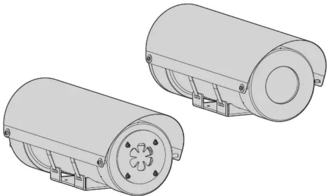
The main parts of the product are illustrated below.
- Sunshield.
- Housing.
- Protective grate (MHXT).
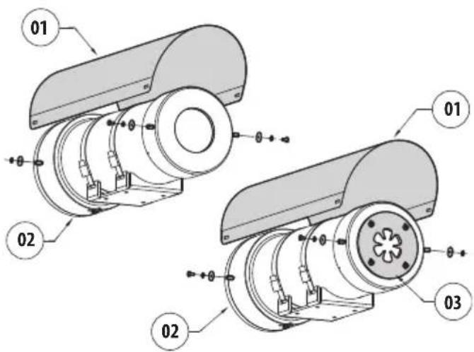
Fig. 1
4.2 Range of use
The unit is designed for use in a fixed location, for surveillance of areas classified as zone 1-21 and zone 2-22 with potentially explosive atmospheres.
The unit has been built and certified in compliance with directive 2014/34/UE and with the international standards IECEX, which define its range of application and minimum safety requirements.
4.3 Specific use conditions
The external surface of the product must never be covered by more than 5 mm of dust.
To avoid accumulation of electrostatic loads during cleaning, the device must be cleaned using a damp cloth.
Contact the manufacturer for information on the dimensions of the flameproof joint.
Use fasteners with property A2 or A4 Class 70, yield stress: 450N / mm^2
4.4 Gas Group, Dust Group and Temperatures
The device is certified for group IIB or IIC (Gas) and group IIIC (Dust).
Ambient temperature: -20°C/+60°C or -40°C/+60°C
| GROUP IIB GAS, IIIC DUST | |
| Temperature class Maximum | ambient temperature |
| T6 / T85°C -40°C/+60°C | |
Tab. 1
| GROUP IIC GAS, IIIC DUSTS | |
| Temperature class Maximum | ambient temperature |
| T6 / T85°C -20°C/+60°C | |
| T6 / T85°C -40°C/+60°C | |
Tab. 2
4.5 Characteristics of installable devices
Cameras and lenses
• Maximum power: 13W
- Dimensions (WxHxL): 80x82x245mm (3.1x3.2x9.6in)
The camera/optics must be of a basic geometric form, and installed at least 10mm from the inner surface of the enclosure window.
The camera/optics to be installed shall not be electromagnetic or contain lasers, continuous wave sources or ultrasonic energy radiating equipment.
The camera/optics to be installed shall not contain cells or batteries.
4.6 Cable entry
The product is supplied with plastic caps for cable entry protection. They cannot be used for installation.
Unused cable entries must be closed using appropriate Ex certified locking devices with "db" and "tb" explosion protection, suitable for the use conditions and installed correctly.
All cable glands shall be Ex certified, as appropriate, with protection type "db" and "tb", suitable for the conditions of use and installed correctly.
When conduit is used, a suitable Ex certified stopping box shall be used, as appropriate, with protection type "db" and "tb", suitable for the conditions of use and installed correctly.
The stopping box must be fitted within 50mm (1.97in) from the enclosure entry.
The cable entry temperatures are specified in the marking.
To maintain the IP level of product use cable glands with appropriate IP level and apply to threads a sealant compliant with standard IEC/EN60079-14.

CAUTION! Connectors/cable glads and cables must be suitable for an operating temperature of at least +30°C above the ambient temperature.
4.7 Product marking
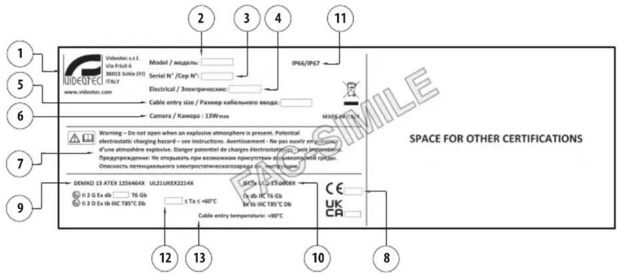
Fig. 2
- Manufacturer's name and address
- Model
- The serial number consists in 12 numeric characters, the second and third digits define the last two numbers of the year of manufacture
- Electrical characteristics (V, A, Hz)
- Type, size and number of cable entries
- Power consumption camera/lens (W).
- Warnings.
-
The number of the accredited body that provides the quality assessment.
-
ATEX marking
- IECEx marking
- IP protection degree
- Ambient temperature
- Cable entry temperature
4.8 Model identification
4.8.1 Housing for Day/Night camera
| MAXIMUS MHX - CONFIGURATION OPTIONS | ||||||||
| Voltage Certification Options | ||||||||
| MHX | 1 | 230Vac | C | IIC -40°C | S | Without wiper | 0 | With sunshield |
| 2 | 24Vac | W | With wiper | |||||
| 3 | 120Vac | |||||||
| 4 | 12Vdc | |||||||
Tab. 3
| MAXIMUS MHX - CERTIFICATIONS AND MARKINGS | |||
| Certification | Marking | Ambient temperature | Cable entry temperature |
| ATEX | II 2G Ex db IIC T6 Gb II 2D Ex tb IIIC T85°C Db | -40°C ≤ Ta ≤ +60°C +90°C | |
| IECEx | Ex db IIC T6 GbEx tb IIIC T85°C Db | ||
| EAC Ex | 1Ex db IIC T6 Gb XEx tb IIIC T85°C Db X | ||
| KCs | Ex db IIC T6 GbEx tb IIIC T85°C Db | ||
| UK Ex | II 2G Ex db IIC T6 Gb II 2D Ex tb IIIC T85°C Db | ||
Tab. 4
4.8.2 Housing for thermal camera
| MAXIMUS MHXT - CONFIGURATION OPTIONS | ||||||
| Voltage | Certification | |||||
| MHXT | 1 230Vac | C IIC -40°C | 0 With sunshield | 00 Without camera | B | |
| 2 24Vac | ||||||
| 3 120Vac | ||||||
Tab. 5
| MAXIMUS MHXT - CERTIFICATIONS AND MARKINGS | |||
| Certification | Marking | Ambient temperature | Cable entry temperature |
| ATEX | II 2G Ex db IIC T6 GbII 2D Ex tb IIIC T85°C Db | -40°C ≤ Ta ≤ +60°C +90°C | °C |
| IECEx | Ex db IIC T6 GbEx tb IIIC T85°C Db | ||
| EAC Ex | 1Ex db IIC T6 Gb XEx tb IIIC T85°C Db X | ||
| KCs | Ex db IIC T6 GbEx tb IIIC T85°C Db | ||
| UK Ex | II 2G Ex db IIC T6 GbII 2D Ex tb IIIC T85°C Db | ||
Tab. 6
5 Preparing the product for use

Before carrying out any type of intervention, read the "Safety rules" chapter of this manual.
5.1 Unpacking
When the product is delivered, make sure that the package is intact and that there are no signs that it has been dropped or scratched.
If there are obvious signs of damage, contact the supplier immediately.
When returning a faulty product we recommend using the original packaging for shipping.
Keep the packaging in case you need to send the product for repairs.
5.2 Contents
Check the contents to make sure they correspond with the list of materials as below:
- Flameproof housing
- Sunshield
• Wiring for motherboards connection - Silicone sheath
- Cable tie
- Spacer and screws for mounting the sunshield
- Plastic spacers and screws 1/4" for camera and lens mounting
• O-ring replacement part kit - Extraction screws
- Wiper brush (version with wiper)
- Instruction manual
5.3 Safely disposing of packaging material
The packaging material can all be recycled. The installer technician will be responsible for separating the material for disposal, and in any case for compliance with the legislation in force where the device is to be used.
6 Installation

Before carrying out any type of intervention, read the "Safety rules" chapter of this manual.
VIDEOTEC strongly recommend to test the product configuration and performance before putting it in the final installation site.
6.1 Installation options
The product can be installed with different brackets and supports. Remember to exclusively use brackets and accessories approved for installation.
The housing can be installed with a slope that varies between ±90^ with reference to the horizon.
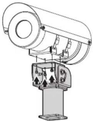
6.1.1 Parapet mounting
First of all secure the base of the adapter to the final destination. Use screws that can bear at least 4 times the weight of the unit.
Apply a generous amount of thread locking compound (Loctite 270).
Tighten the screws.
The thread compound must cure for one hour, allow for this period prior to completing the installation.
It's possible to secure the base (01) to the column adapter NXFWBT using 4 countersunk screws (02) provided.
Secure the joint (03) to the base through nuts and washers supplied.
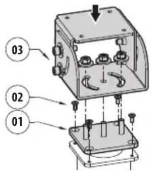
Fig. 3
Fasten the housing at the junction with the screws and washers provided.
natural_image
Technical line drawing of a mechanical device with no visible text or symbolsFig. 4
Apply a generous amount of thread locking compound (Loctite 270).
Tighten the screws.

Pay attention to the fixing. Tightening torque: From 9Nm a 12Nm.
The thread compound must cure for one hour, allow for this period prior to completing the installation.
6.1.2 Bracket mounting
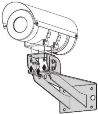
The bracket can be fixed to the vertical wall. Use screws and wall fixing devices that can bear at least four times the weight of the unit.
natural_image
Technical line drawing of a mechanical device with mounting bracket and internal components (no text or symbols)Fig. 5
Then, fix the device to the bracket using the 4 flat washers, the 4 spring washers in stainless steel and the 4 hexagonal head screws in stainless steel (A4 class 70) supplied (M10x20mm).
Make sure the thread are free of dirt and debris.
Apply a generous amount of thread locking compound (Loctite 270) on the 4 screws.
Tighten the screws.

Pay attention to the fixing. Tightening torque: From 9Nm a 12Nm.
The thread compound must cure for one hour, allow for this period prior to completing the installation.
6.1.3 Fixing the unit to the pole mount adapter or corner mount adapter
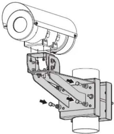
To install the product on a pole or at a wall corner, first of all fix the unit to the wall bracket (6.1.2 Bracket mounting, page 15).
6.1.3.1 Fixing with pole mount
Fix the wall bracket to the pole mount adapter using 4 washers, 4 stainless steel grower washer and 4 hexagon stainless steel bolts (A4 class 70) M10x30mm.
Make sure the thread are free of dirt and debris.
Apply a generous amount of threadlocker (Loctite 270) on the 4 threaded holes on the pole mount adapter.
Tighten the screws.

Pay attention to the fixing. Tightening torque: 35Nm.
The thread compound must cure for one hour, allow for this period prior to completing the installation.
natural_image
Technical line drawing of a mechanical assembly with no visible text or symbolsFig. 6
6.1.3.2 Fixing with corner adapter
Fix the wall bracket to the corner mount adapter using 4 washers, 4 stainless steel grower washers 4 hexagon stainless steel bolts (A4 class 70) M10x30mm.
Make sure the thread are free of dirt and debris.
Apply a generous amount of threadlocker (Loctite 270) on the 4 threaded holes on the corner module.
Tighten the screws.

Pay attention to the fixing. Tightening torque: 35Nm.
The thread compound must cure for one hour, allow for this period prior to completing the installation.

natural_image
Technical diagram of a mechanical assembly with no visible text or symbolsFig. 7
6.2 Sunshield mounting
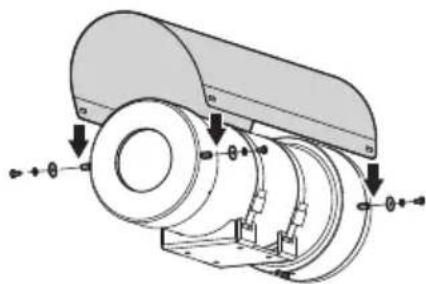
You can fix the sunshield to the housing using the screws supplied.
Apply a generous amount of thread locking compound (Loctite 270) into the threaded holes in the base of the device.
The thread compound must cure for one hour, allow for this period prior to completing the installation.
natural_image
Mechanical assembly diagram showing a cylindrical component with mounting flanges and directional arrows indicating motion (no text or labels)Fig. 8
6.3 Fastening of the wiper blade
Insert the blade on the wiper shaft.
Fasten the wiper brush by means of the flat washer, the toothed washer and the nut.
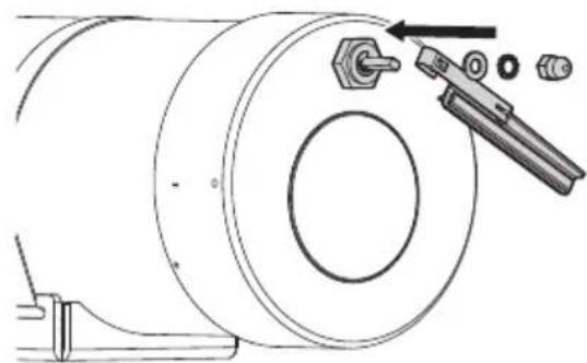
natural_image
Technical line drawing of a mechanical assembly with a cylindrical component and a tool inserted into a housing (no text or symbols)Fig. 9
6.4 Adjusting the protection grid
The protection grid may be adjusted moving it upwards, to fit it with the field of view of certain cameras.

The protective grate must always be present when the product is running.
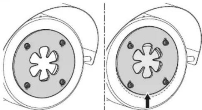
natural_image
Diagram showing two views of a mechanical component with star-shaped cutouts and mounting holes (no text or symbols)Fig. 10
6.5 Housing opening

Before carrying out any type of intervention, read the "Safety rules" chapter of this manual.
To install the camera open the rear flange of the enclosure.
Remove the M6 screws on the rear cover plate of the housing (rear flange).
After removing the screws, the rear flange will remain in place due to the presence of the O-ring.
To facilitate removal of the rear flange and avoid damaging the O-ring, use the 3 x M5x60mm hexagonal head extraction screws supplied.. Once the extraction screws have been inserted, act on them symmetrically (2 or 3 turns at a time per screw) in order to slowly extract the flange.

During opening and closure operations of the product, pay attention not to damage the flameproof joint.
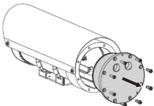
natural_image
Technical line drawing of a cylindrical mechanical device with flanged housing and internal components (no text or symbols)Fig. 11
Screws properties:
• Diameter/Screw pitch: M6x0.8
• Material: A2 or A4 Class 70
- Screw head: ISO 4762
- Length: 18mm
- Yield stress: 450N / mm^2

Disconnect J3 and J8 connectors (version with wiper).
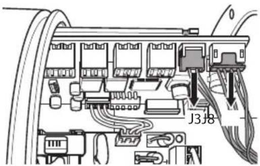
Fig. 12
6.6 Connector board description

To identify the product model, consult the relevant chapter (4.8 Model identification, page 13).
6.6.1 Description of the connectors board for MHX without wiper
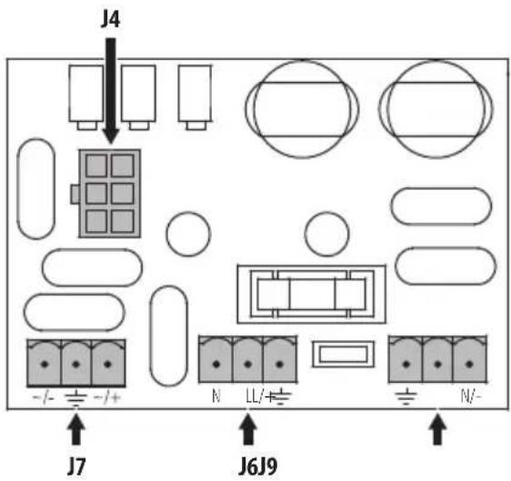
Fig. 13
| BOARD DESCRIPTION | ||
| Connector Function | Terminals - Nominal section of the cables used | |
| J4 jumper – | ||
| J6 Power supply of the camera in 120Vac and 230Vac | from 0.2mm^2 (24AWG) up to 2.5mm^2 (13AWG) | |
| J7 Power supply of the camera in 24Vac and 12Vdc | from 0.2mm^2 (24AWG) up to 2.5mm^2 (13AWG) | |
| J9 Power supply line from 0.2mm^2 | (24AWG) up to 2.5mm^2 (13AWG) | |
Tab. 7
6.6.2 Description of the connectors board for MHX with wiper and for MHXT
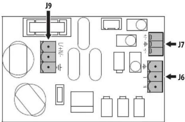
Fig. 14
| BOARD DESCRIPTION | ||
| Connector Function | Terminals - Nominal section of the cables used | |
| J6 Power supply of the camera in 120Vac and 230Vac | from 0.2mm^2 (24AWG) up to 2.5mm^2 (13AWG) | |
| J7 Power supply of the camera in 24Vac and 12Vdc | from 0.2mm^2 (24AWG) up to 2.5mm^2 (13AWG) | |
| J9 Power supply line from 0.2mm^2 | (24AWG) up to 2.5mm^2 (13AWG) | |
Fig. 15
6.6.3 Description of the CPU board for MHX with wiper and for MHXT
EN - English - Instruction manual
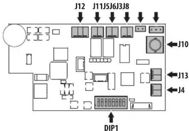
Fig. 16
| BOARD DESCRIPTION | ||
| Connector / Dip-switch | Function Terminals | - Nominal section of the cables used |
| J3 Wiper motor – | ||
| J4 Day/Night camera | output | from 0.2mm ^2 (24AWG) up to 1.0mm ^2 (17AWG) |
| J5 External illuminator | enabling | from 0.2mm ^2 (24AWG) up to 1.0mm ^2 (17AWG) |
| J6 Wiper remote | button | from 0.2mm ^2 (24AWG) up to 1.0mm ^2 (17AWG) |
| J8 Wiper sensors – | ||
| J10 BNC for connection with fibre optic | – | |
| J11 Washer enabling from 0.2mm ^2 | (24AWG) up to 1.0mm ^2 (17AWG) | |
| J12 | RS-485 | from 0.2mm ^2 (24AWG) up to 1.0mm ^2 (17AWG) |
| J13 | Power supply of the camera 12Vdc | from 0.2mm ^2 (24AWG) up to 1.0mm ^2 (17AWG) |
| DIP1 | Serial line configuration | – |
Fig. 17
6.7 Earth ground connection
6.7.1 Earthing equipotential connection
The equipotential connection must be carried out using an external cable with a minimum 4mm^2 section (11AWG).
Connect the cable for the earthing equipotential connection with the eyelet terminal supplied (suitable for cables with 4mm^2(11AWG) up to 6mm^2(9AWG) section).
Fasten the eyelet using the M5 screw and lock washer supplied.
Characteristics of the M5 screw:
- Material: A4
- Screw head: ISO 4762
• Length: 8mm (0.3in) - Yield stress (min): 450 ~N / mm^2

natural_image
Technical line drawing of a mechanical assembly with no visible text or symbolsFig. 18
6.7.2 Connection of the safety earthing
A protective earth cable must be connected to the internal connector (J9, Fig. 19, page 21, Fig. 22, page 22 e Fig. 24, page 23).
6.8 Connecting the power supply

To identify the product model, consult the relevant chapter (4.8 Model identification, page 13).
Depending on the version, the device can be provided with different power supply voltages. The power supply voltage is indicated on the product identification label.
6.8.1 Connection of the power supply line in 24Vac and 12Vdc for MHX without wiper

Insert cables into the product for a sufficient length to facilitate wiring.
Slide the power cables through the entry device.
Pull out the removable terminal (J9, connectors board).

Earth cable should be about 10mm longer than the other two, so that it will not be disconnected accidentally if pulled.

The power supply cable must be covered by the silicone sheath (01) supplied. The silicone sheath must be fastened with the corresponding cable tie (02).
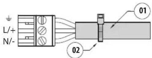
Fig. 19
Reinsert the wired terminal in the connector.
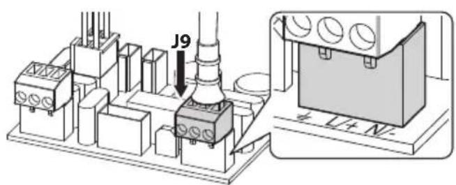
Fig. 20
Check that the jumper is inserted into connector J4.
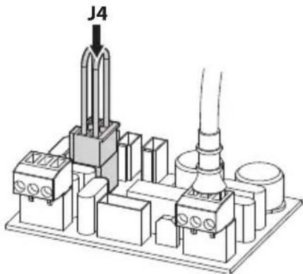
Fig. 21
Power cables to be used: 1.5mm ^2 (15AWG).
- Earth wire type TEWN with cross section equal or bigger than line and neutral cable.
• Line and neutral wire type TFFN or MTW
6.8.2 Connection of the power supply line in 120Vac and 230Vac for MHX without wiper

Insert cables into the product for a sufficient length to facilitate wiring.
Slide the power cables through the entry device. Pull out the removable terminal (J9, connectors board).

Earth cable should be about 10mm longer than the other two, so that it will not be disconnected accidentally if pulled.

The power supply cable must be covered by the silicone sheath (01) supplied. The silicone sheath must be fastened with the corresponding cable tie (02).
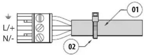
Fig. 22
Reinsert the wired terminal in the connector.
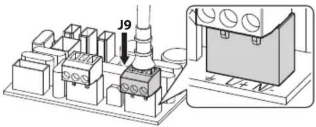
Fig. 23
| CONNECTING THE POWER SUPPLY | |
| Cable colour Terminals | |
| Power supply 230Vac | |
| Blue (N) Neutral | |
| Brown (L) Phase | |
| Yellow/Green Earth | |
| Power supply 120Vac | |
| Blue (N) Neutral | |
| Brown (L) Phase | |
| Yellow/Green Earth | |
Tab. 8
Power cables to be used: 1.5mm^2 (15AWG).
- Earth wire type TEWN with cross section equal or bigger than line and neutral cable.
• Line and neutral wire type TFFN or MTW
6.8.3 Connection of the power supply line in 24Vac, 120Vac, 230Vac and 12Vdc for MHX with wiper and for MHXT

Insert cables into the product for a sufficient length to facilitate wiring.
Slide the power cables through the entry device.
Pull out the removable terminal (J9, connectors board).

Earth cable should be about 10mm longer than the other two, so that it will not be disconnected accidentally if pulled.

The power supply cable must be covered by the silicone sheath (01) supplied. The silicone sheath must be fastened with the corresponding cable tie (02).
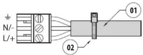
Fig. 24
Reinsert the wired terminal in the connector.
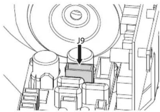
Fig. 25
Power cables to be used: 1.5mm ^2 (15AWG).
- Earth wire type TEWN with cross section equal or bigger than line and neutral cable.
• Line and neutral wire type TFFN or MTW
6.9 How to install the camera/ lens
Compatible cameras (4.5 Characteristics of installable devices, page 11):
• Power consumption (assembly, camera and lens): 13W max
- Cameras dimensions/Lenses that can be installed (WxHxL): 80x82x245mm (3.1x3.2x9.6in) max
- Minimum distance between camera and housing's window: 10mm (0.4in)
Install the camera/lens on the internal slide using the screws and the spacers supplied, so that the installation height allows perfect vision through the window.
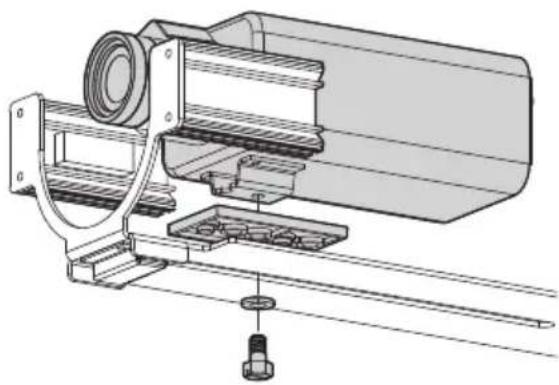
natural_image
Technical line drawing of a mechanical assembly with no visible text or symbolsFig. 26
The minimum installation distance between the camera and the window is 10mm (0.4in). To observe this constraint the camera mount limit is 5mm (0.2in) from the front edge of the inner slide.
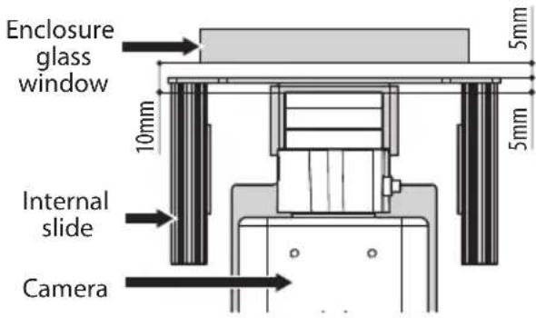
Fig. 27
6.10 Connection of the camera to the power supply

Incorrect wiring can irreparably damage the camera.

The power supply terminal can host cables with the characteristics outlined below.
Nominal section of the cables used: 1.5mm ^2 (15AWG).

To identify the product model, consult the relevant chapter (4.8 Model identification, page 13).
To connect the power supply use the removable terminals supplied.
Carry out the wiring according to the camera's power supply voltage: 12Vdc o 24Vac, 120Vac o 230Vac.
6.10.1 Connection of the camera power supply in 24Vac and 12Vdc for MHX without wiper

In these versions the input voltage will be the voltage of the camera/lens.
Pull out the removable terminal (J7, connectors board). Carry out the wiring between the terminal connector and the camera's power supply terminals. Re-insert the terminal into the connector.
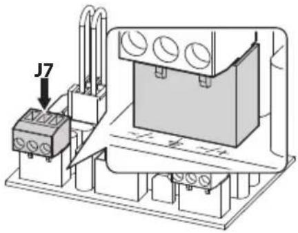
Fig. 28
6.10.2 Connection of the camera power supply in 120Vac and 230Vac for MHX without wiper

In these versions the input voltage will be the voltage of the camera/lens.
Pull out the removable terminal (J6, connectors board). Carry out the wiring between the terminal connector and the camera's power supply terminals. Re-insert the terminal into the connector.
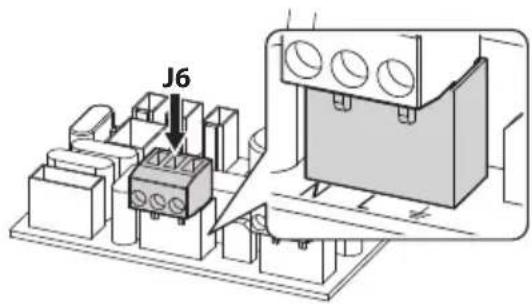
Fig. 29
6.10.3 Connection of the camera power supply in 24Vac, 120Vac, 230Vac and 12Vdc for MHX with wiper and for MHXT
Remove the removable terminal from the board. Carry out the wiring between the removable terminal and the camera's power supply terminals. Re-insert the terminal into the connector.
| CONNECTION OF THE CAMERA TO THE POWER SUPPLY | ||||
| Housing power voltage | ||||
| Camera power supply voltage | 12Vdc 2 | 4Vac | 120Vac | 230Vac |
| Connector board | ||||
| 230Vac - - - J6 | ||||
| 120Vac - - J6 - | ||||
| 24Vac - J7 J7 J7 | ||||
| CPU board | ||||
| 12Vdc J13 J13 J13 J13 | ||||
Tab. 9
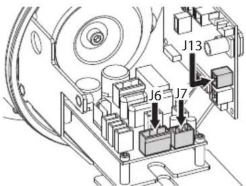
Fig. 30
6.11 Camera with analogue video output

CDS installation type (Cable Distribution System). The installation is type TNV-1, do not connect it to SELV circuits.
The video signal coming from an analogue camera can be transmitted via a coaxial cable or optical fibre.
Suggested coaxial cables are:
- RG59
- RG174A/U UL1354
Slide the coaxial cable through the entry device.
Connect the coaxial cable to the camera's BNC video connector. Use a 75Ohm BNC male connector (not supplied).
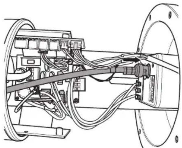
natural_image
Technical line drawing of a mechanical assembly with cables and connectors (no text or symbols)Fig. 31
6.12 Optical fiber connection

Use a type of optical fiber suitable for the receiver model installed.
Video and data transmission can be made via optical fiber.
Connect the camera's video output to the CPU board's J10 connector. Use the appropriate BNC-BNC cable supplied.
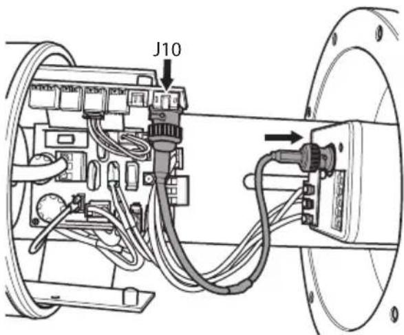
Fig. 32
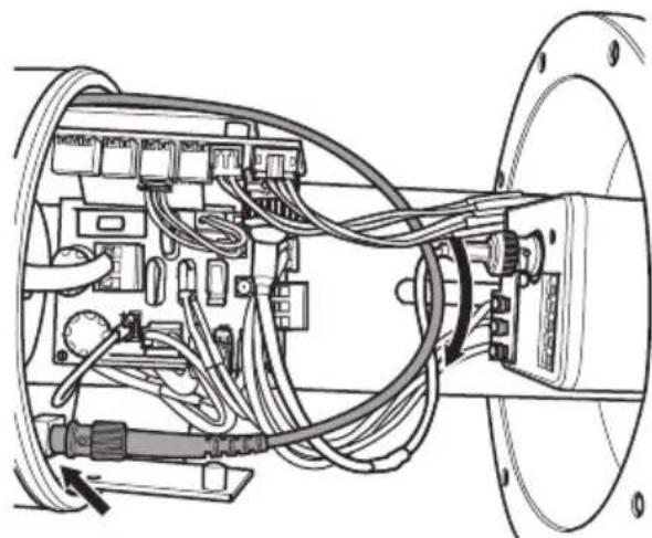
For Multi Mode fibre transmitters use fibre 62.5/125μm with a maximum length of 3km (1.9mi).
For Single Mode fibre transmitters use fibre 9/125μm with a maximum length of 69km (42.9mi).
Slide the fiber through the entry device.
Connect optical fiber with ST type connector.
Connect the optical fibre to the transceiver board by paying attention to the bending radius.

For further details please refer to the manual of the optical fibre receiver.
natural_image
Technical diagram of an electrical enclosure with wiring and components (no visible text or labels)Fig. 33
6.13 IP camera with digital data transmission

If the camera has a RS-485 output refer to the relative chapter (6.14 Connection of the IP camera's RS-485 output, page 27).

CDS installation type (Cable Distribution System). The installation is type TNV-1, do not connect it to SELV circuits.
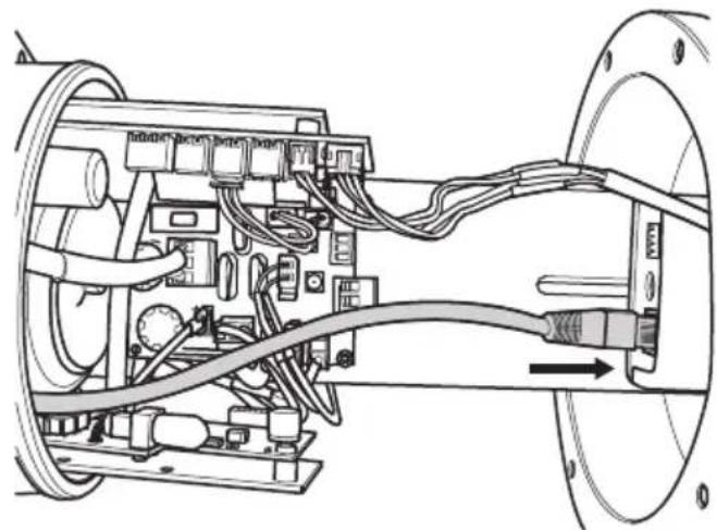
To connect the net cable a UTP is required: Category 5E or 6A, 4 pair, maximum length 100m (328ft).
Join the Ethernet cable end-to-end to an RJ45 connector.
Direct crimping is required if the product is connected to a hub or switch. Cross crimping is required if the product is connected directly to a PC.
natural_image
Technical diagram of an electrical connector assembly with wiring and components (no text or labels)Fig. 34
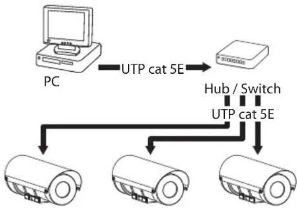
The example below shows a typical installation.
flowchart
graph TD
    PC["PC"] -->|UTP cat 5E| Host["Host"]
    Host -->|UTP cat 5E| Device1["Device 1"]
    Host -->|UTP cat 5E| Device2["Device 2"]
    Host -->|UTP cat 5E| Device3["Device 3"]
    PC --> Hub["Hub / Switch"]
Fig. 35 Typical installation.
6.14 Connection of the IP camera's RS-485 output
If you are using an IP camera with output RS-485 it is possible to use this communication channel to send telemetry commands. (Tab. 13, page 29). The commands are sent from the camera to the CPU board. The camera must support the PELCO D (2400baud, 9600baud) or VIDEOTEC MACRO protocols (9600baud, 38400baud).
Connect the camera's RS-485 output to the CPU board's J12 connector.
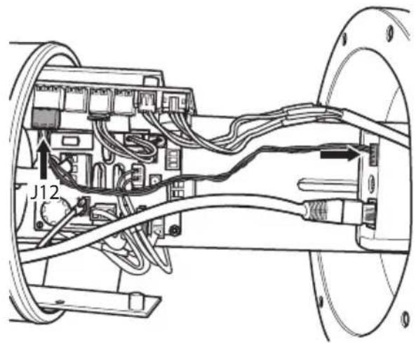
Fig. 36
| CONNECTION OF THE RS-485 SERIAL OUTPUT | |
| Terminal Description | |
| A (+) RS-485 A | |
| B (-) RS-485 B | |
| AGND Reference line | RS-485 |
Tab. 10
6.15 Serial line connection

CAUTION! TNV-1 installation type. The installation is type TNV-1, do not connect it to SELV circuits.

CAUTION! In order to reduce the risk of fire, only use cables with sections greater than or equal to 0.14mm ^2 (26AWG).
The product includes a one-directional communication serial line RS-485 that is internally terminated. The line works with PELCO D (2400baud, 9600baud) or VIDEOTEC MACRO protocol (9600baud, 38400baud), length 1200m max.
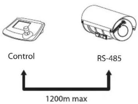
Fig. 37
The line can be configured using the board's DIP1 selector dip-switch.
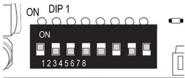
Fig. 38
Feed the serial line cables through the input device.
Connect the control cables to the removable terminal (J12, CPU board). Connect the cables as described in the table.
| CONNECTION OF THE RS-485 SERIAL OUTPUT | |
| Terminal Description | |
| A (+) RS-485 A | |
| B (-) RS-485 B | |
| AGND Reference line | RS-485 |
Tab. 11
Reinsert the wired terminal in the connector. Gather the cables with a cable tie.
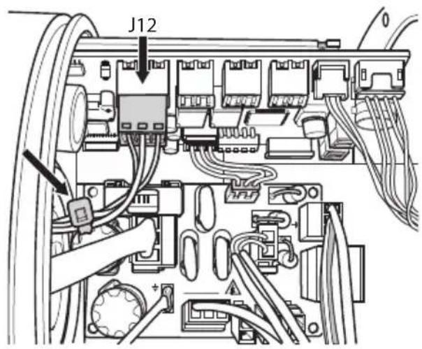
Fig. 39

When the switch rocker is up it represents the value 1 (ON). When the dip-switch rocker is down it represents the value 0 (OFF).
| CONFIGURATION OF THE DIP-SWITCHES (DIP 1) | |||||||||
| Description | SW1 | SW2 | SW3 | SW4 | SW5 | SW6 | SW7 | SW8 | Configuration |
| Address | OFF | OFF | OFF | OFF | OFF | - | - | - | Reserved |
| Address | ON | OFF | OFF | OFF | OFF | - | - | - | Address 01 |
| Address | OFF | ON | OFF | OFF | OFF | - | - | - | Address 02 |
| Address | ON | ON | OFF | OFF | OFF | - | - | - | Address 03 |
| ...... ... ...... --- ... | |||||||||
| Address | ON | ON | ON | ON | ON | - | - | - | Address 31 |
| Baud rate - - - - - ON - - 9600baud (PELCO D), | 38400baud (VIDEOTEC MACRO) | ||||||||
| Baud rate - - - - - OFF - - 2400baud (PELCO D), | 9600baud (VIDEOTEC MACRO) | ||||||||
| Protocol | - - - - - ON - PELCO D | ||||||||
| Protocol | - | - | - | - | - | - | OFF | - | VIDEOTEC MACRO |
| Pre-installed module | - | - | - | - | - | - | - | ON | SONY |
| Pre-installed module | OFF OFF | OFF OFF | OFF OFF | OFF OFF | OFF FLIR | ||||
Tab. 12
6.15.1 Special controls
| SPECIAL CONTROLS | ||
| Action | Command | |
| Protocol | ||
| PELCO D | VIDEOTEC MACRO | |
| Wiper Start | Save Preset 85 | Save Preset 85 |
| Aux 3 ON | Aux 3 ON | |
| Wip+ | ||
| Wiper Stop | Save Preset 86 | Save Preset 86 |
| Aux 3 OFF | Aux 3 OFF | |
| Wip- | ||
| Washer Start | Save Preset 87 | Save Preset 87 |
| Aux 4 ON | Aux 4 ON | |
| Was+ | ||
| Washer Stop | Save Preset 97 | Save Preset 97 |
| Aux 4 OFF | Aux 4 OFF | |
| Was- | ||
| Night Mode On | Save Preset 88 | Save Preset 88 |
| Aux 2 ON | Aux 2 ON | |
| Aux+ | ||
| Night Mode Off | Save Preset 89 | Save Preset 89 |
| Aux 2 OFF | Aux 2 OFF | |
| Aux- | ||
| Reboot | Save Preset 94 | Save Preset 94 |
Tab. 13
6.16 Enabling the wiper
6.16.1 Enable from the remote button
The wiper can be operated remotely using an NO (normally open) dry contact. The command has a range of about 200m (656ft) and can be achieved with an unshielded cable with a 0.25mm ^4 minimum section (24AWG).
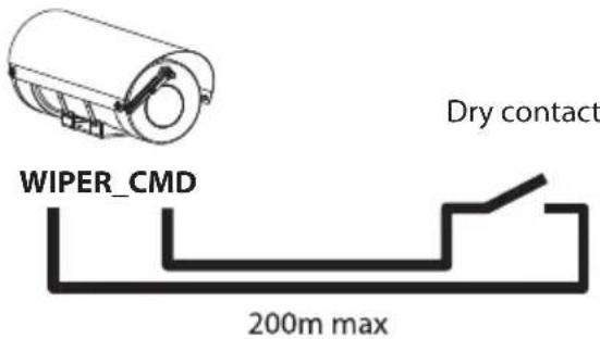
Fig. 40
Feed the control cables through the input device.
Pull out the removable terminal (J6, CPU board).
Connect the control cables.
Reinsert the wired terminal in the connector. Gather the cables with a cable tie.

All signal cables must be grouped together by means of a cable tie.
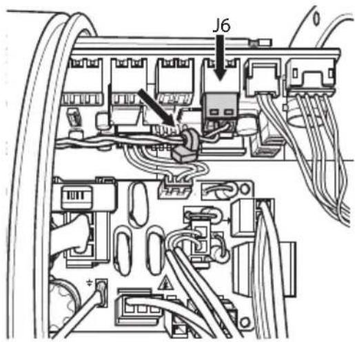
Fig. 41

Before closing the housing, connect connectors J3 and J8 of the wiper.
6.16.2 Enable from the keyboard
If the serial communication line is being used, the wiper can be enabled from the keyboard (6.15 Serial line connection, page 28).
6.17 Enabling the washer (Washer)

Relay operating specifications.
- Working voltage: 30Vac max or 60Vdc max.
- Current: 1A max.
Use suitable cable sections: from 0.2mm ^2 (30AWG) up to 1mm ^2 (16AWG).

All signal cables must be grouped together by means of a cable tie.
If the serial communication line is being used, the washer can be enabled from the keyboard (6.15 Serial line connection, page 28).
Activation takes place via the closure of the dry contact of a relay.
Due to the absence of polarity, both terminals of the same relay can be connected either to alternating or direct current voltages.
Feed the control cables through the input device.
Pull out the removable terminal (J11, CPU board). Connect the control cables.
Reinsert the wired terminal in the connector. Gather the cables with a cable tie.
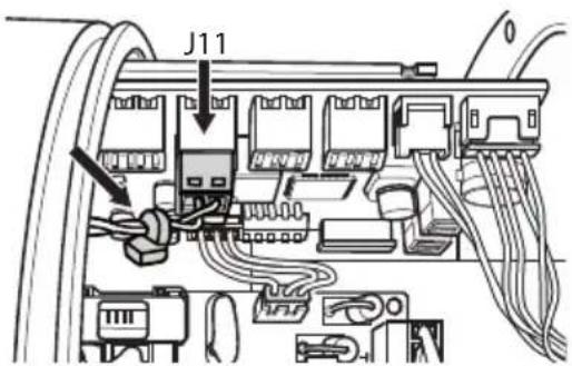
Fig. 42

For further details on configuration and use, refer to the relative manual.
6.18 Enable an external illuminator from the day/night camera output
The camera could be equipped with a day/night dry contact output that can be used to enable an external illuminator.
Pull out the removable terminal (J4, CPU board).
Connect the camera's day/night output.
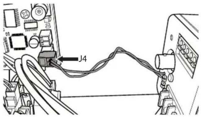
Fig. 43
Due to the absence of polarity, both terminals of the same relay can be connected either to alternating or direct current voltages.
Feed the control cables through the input device.
Activation takes place via the closure of the dry contact of a relay.
Pull out the removable terminal (J5, CPU board).
Connect the control cables.
Reinsert the wired terminal in the connector. Gather the cables with a cable tie.
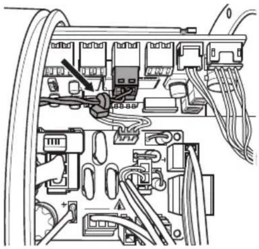
natural_image
Interior view of an electronic device showing internal components and wiring (no text or symbols visible)Fig. 44

Relay operating specifications.
- Working voltage: 30Vac max or 60Vdc max.
- Current: 1A max.
Use suitable cable sections: from 0.2mm ^2 (30AWG) up to 1mm ^2 (16AWG).
6.19 Housing closure

Test system operation for positive results before closing the product and allowing the presence of a hazardous atmosphere.

During opening and closure operations of the product, pay attention not to damage the flameproof joint.
Insert the slide into the case by sliding it under the guides.
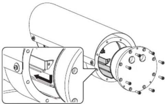
natural_image
Technical line drawing of a mechanical assembly with two views: top shows cylindrical components, bottom shows flanged circular components (no text or symbols)Fig. 45

Before closing the rear flange of the product, replace the O-ring gasket.
Verify that there is no dirt or debris.
Lubricate the threads with grease compliant with IEC/EN60079-14 to facilitate screwing the cover on.
Arrange the cables so that there is no interference during the back cover closure.

In the integrated wiper version connect the wiring before closing the housing. (6.16 Enabling the wiper, page 30).
Insert the rear flange if the housing body having aligned holes in between the two parts.

Be very careful not to damage the O-ring gasket.
Screw back the previously removed screws.

Pay attention to the fixing. Tightening torque: From 9Nm a 12Nm.
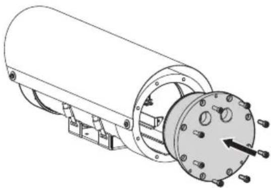
natural_image
Technical line drawing of a cylindrical mechanical assembly with mounting flanges and a central housing (no text or symbols)Fig. 46
7 Switching on

Ensure the unit and the other components of the system are appropriately closed to prevent contact with live parts.

Make sure that all parts are fastened down firmly and safely.

The automatic pre-heating (De-Ice) process could be started whenever the device is switched on and the ambient temperature is below -10°C (+14°F). The procedure is necessary to guarantee correct operation of the devices even at low temperatures. Pre-heating procedure length: 60 minutes.
The unit is switched on by connecting the power supply.
It takes a few minutes for the unit to become fully operational after it is switched on.
To switch off the unit disconnect the power.
8 Maintenance

Before carrying out any type of intervention, read the "Safety rules" chapter of this manual.
8.1 Routine maintenance
When contacting VIDEOTEC for assistance please provide the serial number and the identification code of the model.
Use only VIDEOTEC original spare parts.
8.1.1 Inspecting the cables
The cables should not show signs of damage or wear, which could generate hazardous situations. In cases of damaged or worn cables, repair or replacement will be required.
8.1.2 Replacing the gasket
After each opening of the product replace the O-ring gasket before closing the product. Use only VIDEOTEC original spare parts.
Open and close the rear flange of the product as described in the chapters above.
Replace O-ring gasket paying attention to position it correctly.
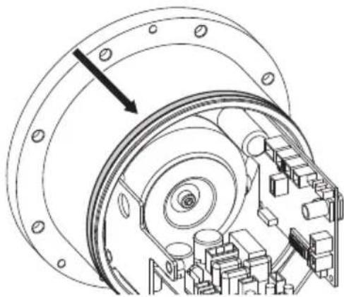
natural_image
Technical line drawing of a mechanical assembly with concentric components and a directional arrow (no text or symbols)Fig. 47
8.2 Extraordinary maintenance
8.2.1 Fuses replacement

CAUTION! To ensure protection against the risk of fire, replace the fuse with one the same type and value. The fuse must only be replaced by qualified staff.
If necessary, the connector board's fuse can be replaced. The new fuse must comply with the directions given in the table.
| FUSES REPLACEMENT | |
| Supply voltage Fuse (FUS1) | |
| 12Vdc T 4A H 250V 5x20 | |
| 24Vac, 50/60Hz T 4A H 250V 5x20 | |
| 120Vac, 50/60Hz T 1A L 250V 5x20 | |
| 230Vac, 50/60Hz T 1A L 250V 5x20 | |
Tab. 14
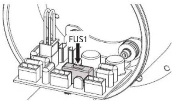
Fig. 48 MHX without wiper.
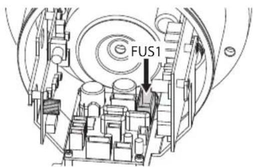
Fig. 49 MHX with wiper and MHXT.
9 Cleaning

Before carrying out any type of intervention, read the "Safety rules" chapter of this manual.

Frequency will depend on the type of environment in which the product is used.
9.1 Cleaning the glass window
Cleaning should be done with mild soap diluted with water.
9.2 Cleaning the germanium window

When the unit is working the protection grid must always be installed. Failure to follow this instruction may create serious safety hazards for people and for the installation, and will also invalidate the warranty.

When cleaning the window, take care not to scratch or damage the outer surface treated with carbon coating. Damage to this coating could also interfere with the transparency of the surface to infrared light.
Cleaning should be done with mild soap diluted with water.
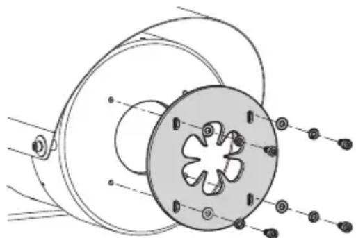
Remove the protective grid unscrewing the screws and washers on the front of the enclosure using a spark-proof tool.
natural_image
Technical line drawing of a mechanical component with no visible text or symbolsFig. 50
After the cleaning, mount the protection grid with its screws and washers.
9.3 Cleaning the product

The outside surface of the product must never be covered in more than 5 mm of dust.

The cleaning of the product should be carried out according to the instructions in this chapter in order to prevent accumulation of electrostatic charges.
The device should be cleaned using a damp cloth; compressed air must not be used.
10 Information on disposal and recycling
The European Directive 2012/19/EU on Waste Electrical and Electronic Equipment (WEEE) mandates that these devices should not be disposed of in the normal flow of municipal solid waste, but they should be collected separately in order to optimize the recovery stream and recycling of the materials that they contain and to reduce the impact on human health and the environment due to the presence of potentially hazardous substances.
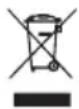
The symbol of the crossed out bin is marked on all products to remember this.
The waste may be delivered to appropriate collection centers, or may be delivered free of charge to the distributor where you purchased the equipment at the time of purchase of a new equivalent or without obligation to a new purchase for equipment with size smaller than 25cm (9.8in).
For more information on proper disposal of these devices, you can contact the responsible public service.
11 Troubleshooting

Contact the VIDEOTEC technical service or an authorized support centre if the problems listed below persist or you have any other issues that are not described here.
When contacting VIDEOTEC for assistance please provide the serial number and the identification code of the model.
PROBLEM The product does not go on.
CAUSE Wiring error, blown fuse.
SOLUTION Make sure the connections are correct. Check the continuity of the fuses and replace them with the indicated models should they fail.
PROBLEM The wiper is frozen and unresponsive to commands.
CAUSE The wiper is either jammed or broken.
SOLUTION Check that the wiper is free to move.
12 Technical data
12.1 MAXIMUS MHX
12.1.1 General
AISI 316L stainless steel construction
Passivated and electropolished external surfaces
Silicone O-ring seals
12.1.2 Mechanical
2 holes 3/4" NPT for cable entry
Sunshield
Unit weight: 16.5kg (36lb)
Tempered window glass
- Usable diameter: 75mm (3.0in)
- Thick: 12mm (0.47in)
12.1.3 Electrical
Supply voltage/Current consumption/Power:
• 230Vac, 0.34A, 50/60Hz, 80W
• 120Vac, 0.5A, 50/60Hz, 60W
• 24Vac, 2.2A, 50/60Hz, 53W
- 12Vdc, 2.8A, 34W
Heater (Ton 15°C±4°C (59°F±7°F), Toff 22°C±3°C (72°F±5°F))
12.1.4 Serial communications
Serial interface: 1 RS-485 line, half-duplex
Addressable units: Up to 31, via dip-switch
Protocols:
• PELCO D: 2400baud, 9600baud
• VIDEOTEC MACRO: 9600baud, 38400baud
PELCO is registered trademark.
The product may be interfaced with devices not manufactured by VIDEOTEC. It is possible that the interface protocols have changed or are in a different configuration from earlier tested units by VIDEOTEC. VIDEOTEC recommends a test prior to installation. VIDEOTEC will not be liable for any installation costs or lost revenues in the event a compatibility problem will occur.
12.1.5 I/O
Version with wiper
- Remote wiper activation: 1 input, dry contact NO
• Day/Night camera status: 1 input
- Wash system activation relay: 1 output, 60Vdc max or 30Vac max, 1A
- Illuminator activation relay: 1 output, 60Vdc max or 30Vac max, 1A
12.1.6 Cameras
Compatible cameras:
- Power consumption (assembly, camera and lens): 13W max
- Cameras dimensions/Lenses that can be installed (WxHxL): 80x82x245mm (3.1x3.2x9.6in) max
- Minimum distance between camera and housing's window: 10mm (0.4in)
12.1.7 Environment
For indoors and outdoors installation
Operating temperature/Installation temperature: from -40°C (-40°F) up to +60°C (140°F)
Relative humidity: from 5% up to 95%
12.1.8 Certifications
Electrical safety (CE): EN60950-1, IEC60950-1, EN62368-1, IEC62368-1
Electromagnetic compatibility (CE): EN61000-6-4, EN61000-3-2, EN61000-3-3, EN50130-4, EN55032 (Class A)
RoHS (CE): EN IEC 63000
Outdoor installation (CE): EN60950-22, IEC60950-22
IP protection degree (EN/IEC60529): IP66, IP67
Vibration test: EN50130-5, EN60068-2-6
12.1.9 Certifications - Explosion-proof applications
ATEX (EN IEC 60079-0, EN 60079-1, EN 60079-31)
IECEx (IEC 60079-0, IEC 60079-1, IEC 60079-31)
EAC EX (TR CU 012/2011)
KCs (Employment and labor department 2021-22)
UK Ex (EN IEC 60079-0, EN 60079-1, EN 60079-31)
12.2 MAXIMUS MHXT
12.2.1 General
AISI 316L stainless steel construction
Passivated and electropolished external surfaces
Silicone O-ring seals
12.2.2 Mechanical
2 holes 3/4" NPT for cable entry
Window with protection grid
Sunshield
Unit weight: 16.5kg (36lb)
12.2.3 Housing's window
Germanium window
• Usable diameter: 56mm (2.2in)
- Thick: 10mm (0.4in)
• External treatment: antiscratch (Hard Carbon Coating - DLC), antireflection
• Internal treatment: antireflection
• Spectral range: from 7.5μm up to 14μm
• Medium transmittance (from 7.5μm up to 11.5μm): 87.3%
• Medium transmittance (from 11.5μm up to 14μm): 67.3%
12.2.4 Electrical
Supply voltage/Current consumption/Power:
• 230Vac, 0.34A, 50/60Hz, 80W
• 120Vac, 0.5A, 50/60Hz, 60W
• 24Vac, 2.2A, 50/60Hz, 53W
- 12Vdc, 2.8A, 34W
Heater (Ton 15°C±4°C (59°F±7°F), Toff 22°C±3°C (72°F±5°F))
12.2.5 Serial communications
Serial interface: 1 RS-485 line, half-duplex
12.2.6 Cameras
Compatible cameras:
- Power consumption (assembly, camera and lens): 13W max
- Cameras dimensions/Lenses that can be installed (WxHxL): 80x82x245mm (3.1x3.2x9.6in) max
- Minimum distance between camera and housing's window: 10mm (0.4in)
12.2.7 Environment
For indoors and outdoors installation
Operating temperature/Installation temperature: from -40°C (-40°F) up to +60°C (140°F)
Relative humidity: from 5% up to 95%
12.2.8 Certifications
Electrical safety (CE): EN60950-1, IEC60950-1, EN62368-1, IEC62368-1
Electromagnetic compatibility (CE): EN61000-6-4, EN61000-3-2, EN61000-3-3, EN50130-4, EN55032 (Class A)
RoHS (CE): EN IEC 63000
Outdoor installation (CE): EN60950-22, IEC60950-22
IP protection degree (EN/IEC60529): IP66, IP67
Vibration test: EN50130-5, EN60068-2-6
Electromagnetic compatibility (North America): FCC part 15 (Class A)
KC certification (certification only valid for the code: MHXT1C000B)
12.2.9 Certifications - Explosion-proof applications
ATEX (EN IEC 60079-0, EN 60079-1, EN 60079-31)
IECEx (IEC 60079-0, IEC 60079-1, IEC 60079-31)
EAC EX (TR CU 012/2011)
KCs (Employment and labor department 2021-22)
UK Ex (EN IEC 60079-0, EN 60079-1, EN 60079-31)
13 Technical drawings
The indicated measurements are expressed in millimetres.

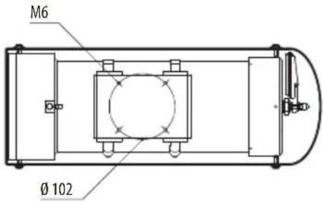
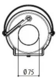
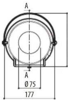
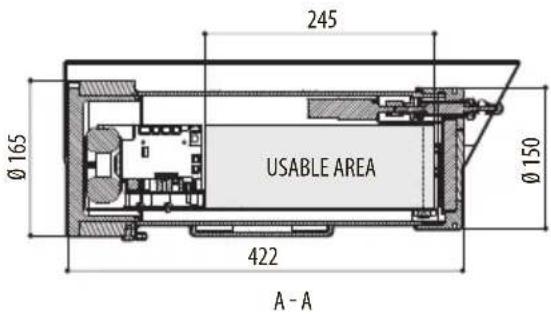
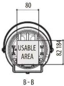
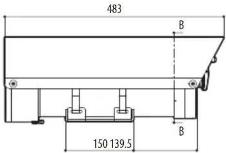
Fig. 51 MAXIMUS MHX.
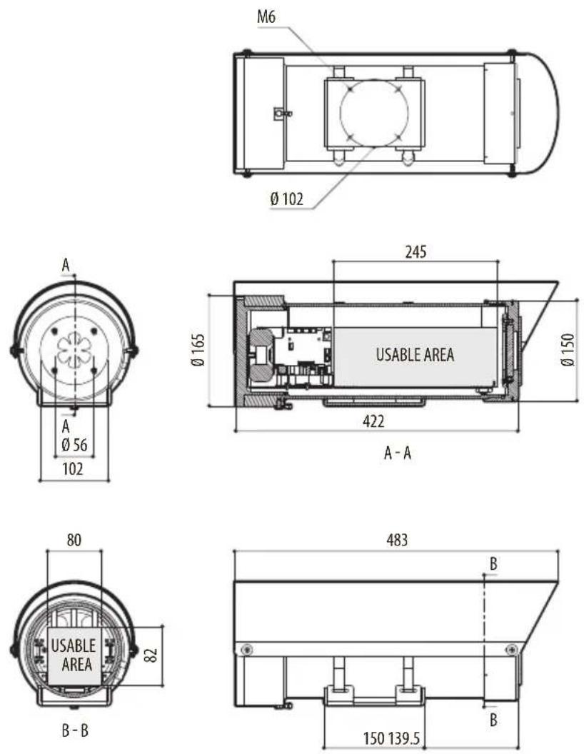
Fig. 52 MAXIMUS MHXT.
MAXIMUS MHX, MAXIMUS MHXT
natural_image
Technical line drawing of two cylindrical electronic components with mounting brackets and a central hub (no text or symbols)Sommario
Fig. 1
natural_image
Technical line drawing of a mechanical device with mounting base and cylindrical housing (no text or symbols)Fig. 4
natural_image
Technical line drawing of a mechanical device with mounting bracket and internal components (no text or symbols)Fig. 5
natural_image
Technical line drawing of a mechanical assembly with no visible text or symbolsFig. 6
natural_image
Technical diagram of a mechanical assembly with no visible text or symbolsFig. 7
natural_image
Mechanical assembly diagram showing a cylindrical component with mounting flanges and directional arrows indicating motion (no text or labels)Fig. 8
natural_image
Technical line drawing of a mechanical assembly with a cylindrical component and a tool inserted into it (no text or symbols present)Fig. 9
natural_image
Diagram showing two views of a mechanical component with star-like cutouts, one with mounting holes and the other with a black arrow pointing to a feature (no text or symbols present)Fig. 10
natural_image
Technical line drawing of a cylindrical mechanical device with mounting flanges and internal components (no text or symbols)Fig. 11
natural_image
Technical line drawing of a mechanical assembly with a magnified inset showing internal components (no text or symbols)Fig. 18
Fig. 19
Fig. 20
Fig. 22
Fig. 23
Fig. 24
natural_image
Technical line drawing of a mechanical assembly with no visible text or symbolsFig. 26
natural_image
Technical line drawing of a mechanical assembly with cables and components (no text or symbols)Fig. 31
natural_image
Technical diagram of an electrical or mechanical assembly with visible wiring and components (no text or labels)Fig. 33
natural_image
Technical diagram of an electrical connector assembly with cables and components (no text or labels)Fig. 34
Fig. 40
natural_image
Interior view of an electronic device showing internal components and wiring (no text or symbols visible)Fig. 44

natural_image
Technical line drawing of a mechanical assembly with flanged components and a magnified inset showing internal components (no text or symbols)Fig. 45

natural_image
Technical line drawing of a cylindrical mechanical assembly with mounting flanges and a central housing (no text or symbols)Fig. 46
7 Accensione

natural_image
Technical line drawing of a mechanical assembly with concentric components and a directional arrow (no text or symbols)Fig. 47
natural_image
Technical diagram of a mechanical component with labeled parts (no text or symbols present)Fig. 50
KCs (Employment and labor department 2021-22)
UK Ex (EN IEC 60079-0, EN 60079-1, EN 60079-31)
12.2 MAXIMUS MHXT
12.2.1 Generale
KCs (Employment and labor department 2021-22)
UK Ex (EN IEC 60079-0, EN 60079-1, EN 60079-31)
13 Disegni tecnici

natural_image
Technical line drawing of two cylindrical electronic components with mounting brackets and a central hub (no text or symbols)Sommaire
6 Installation....14
Fig. 1
natural_image
Technical line drawing of a mechanical device with mounting base and cylindrical housing (no text or symbols)Fig. 4
natural_image
Technical line drawing of a mechanical device with mounting bracket and internal components (no text or symbols)Fig. 5
natural_image
Technical line drawing of a mechanical assembly with no visible text or symbolsFig. 6
natural_image
Technical line drawing of a mechanical assembly with no visible text or symbolsFig. 7
natural_image
Mechanical assembly diagram showing a cylindrical component with mounting flanges and directional arrows indicating motion (no text or labels)Fig. 8
natural_image
Technical line drawing of a mechanical assembly with a cylindrical component and a tool inserted into it (no text or symbols present)Fig. 9
natural_image
Diagram showing two views of a mechanical component with a star-like cutout, no text or symbols presentFig. 10
natural_image
Technical line drawing of a cylindrical mechanical device with mounting flanges and internal components (no text or symbols)Fig. 11
natural_image
Technical diagram of a mechanical assembly with a magnified inset showing a component detail (no text or symbols present)Fig. 18
Fig. 19
Fig. 22
Fig. 23
| CONNEXION DE LA LIGNE D'ALIMENTATION | |
| Couleur du cable Bornes | |
| Alimentation 230Vac | |
| Bleue (N) Neutre | |
| Marron (L) Phase | |
| Jaune/Vert Terre | |
| Alimentation 120Vac | |
| Bleue (N) Neutre | |
| Marron (L) Phase | |
| Jaune/Vert Terre | |
Tab. 8
Fig. 24
natural_image
Technical line drawing of a mechanical assembly with no visible text or symbolsFig. 26
natural_image
Technical line drawing of a mechanical assembly with cables and components (no text or symbols)Fig. 31
natural_image
Technical diagram of an electrical enclosure with wiring and components (no visible text or labels)Fig. 33
natural_image
Technical diagram of an electrical connector assembly with cables and components (no text or labels)Fig. 34
Fig. 40
natural_image
Interior view of an electronic device showing internal components and wiring (no text or symbols visible)Fig. 44

natural_image
Technical line drawing of a mechanical assembly with internal components and mounting holes (no text or symbols)Fig. 45

natural_image
Technical line drawing of a cylindrical mechanical assembly with mounting flanges and a central housing (no text or symbols)Fig. 46
7 Allumage

natural_image
Technical line drawing of a mechanical assembly with concentric components and a directional arrow (no text or symbols)Fig. 47
8.2 Entretien extraordinaire
natural_image
Technical diagram of a mechanical component with labeled parts (no text or symbols present)Fig. 50
12.1.8 Certifications
KCs (Employment and labor department 2021-22)
UK Ex (EN IEC 60079-0, EN 60079-1, EN 60079-31)
12.2 MAXIMUS MHXT
12.2.1 Généralités
Construction en acier inox AISI 316L
12.2.8 Certifications
12.2.9 Certifications - Applications anti-déflagrations
ATEX (EN IEC 60079-0, EN 60079-1, EN 60079-31)
IECEx (IEC 60079-0, IEC 60079-1, IEC 60079-31)
EAC EX (TR CU 012/2011)
KCs (Employment and labor department 2021-22)
UK Ex (EN IEC 60079-0, EN 60079-1, EN 60079-31)
13 Dessins techniques

natural_image
Technical line drawing of two cylindrical electronic components with mounting brackets and a central hub (no text or symbols)Inhaltsverzeichnis
1 Allgemeines....7
6 Installation....14
6.1 Montageoptionen....14
natural_image
Technical line drawing of a mechanical device with mounting base and control panel (no text or symbols)Abb. 4
natural_image
Technical line drawing of a mechanical device with mounting bracket and internal components (no text or symbols)Abb. 5
natural_image
Technical line drawing of a mechanical assembly with no visible text or symbolsAbb. 6
natural_image
Technical diagram of a mechanical assembly with no visible text or symbolsAbb. 7
natural_image
Mechanical assembly diagram showing a cylindrical component with mounting flanges and directional arrows indicating motion (no text or labels)Abb. 8
natural_image
Technical line drawing of a cylindrical mechanical component with a tool inserted, showing no text or symbols.Abb. 9
natural_image
Diagram showing two views of a mechanical component with four circular features and mounting holes, no text or symbols present.Abb. 10
natural_image
Technical line drawing of a cylindrical mechanical device with flanged housing and internal components (no text or symbols)Abb. 11
natural_image
Technical line drawing of a mechanical assembly with a magnified inset showing internal components (no text or symbols)Abb. 18
Abb. 19
Abb. 22
Abb. 23
Abb. 24
natural_image
Technical line drawing of a mechanical assembly with no visible text or symbolsAbb. 26
natural_image
Technical line drawing of a mechanical assembly with cables and components (no text or symbols)Abb. 31
natural_image
Technical diagram of an electrical connector assembly with wiring and components (no text or labels)Abb. 33
natural_image
Technical diagram of an electrical connector assembly with wiring and components (no text or labels)Abb. 34
natural_image
Interior view of an electronic device showing internal components and wiring (no text or symbols visible)Abb. 44

natural_image
Technical line drawing of a mechanical assembly showing internal components and a close-up view (no text or symbols)Abb. 45

natural_image
Technical line drawing of a mechanical assembly with a cylindrical component and mounting flanges (no text or symbols)Abb. 46
7 Einschaltung

natural_image
Technical line drawing of a mechanical assembly with concentric components and a directional arrow (no text or symbols)Abb. 47
natural_image
Technical line drawing of a mechanical component with no visible text or symbolsAbb. 50
KCs (Employment and labor department 2021-22)
UK Ex (EN IEC 60079-0, EN 60079-1, EN 60079-31)
12.2 MAXIMUS MHXT
12.2.1 Allgemeines
KCs (Employment and labor department 2021-22)
UK Ex (EN IEC 60079-0, EN 60079-1, EN 60079-31)
natural_image
Technical line drawing of two cylindrical electronic components with mounting brackets and a central hub (no text or symbols)natural_image
Technical line drawing of a mechanical device with mounting base and cylindrical housing (no text or symbols)Fig. 4
natural_image
Technical line drawing of a mechanical device with mounting bracket and internal components (no text or symbols)Fig. 5
natural_image
Technical line drawing of a mechanical assembly with no visible text or symbolsFig. 6
natural_image
Technical line drawing of a mechanical assembly with no visible text or symbolsFig. 7
natural_image
Mechanical assembly diagram showing a cylindrical component with mounting flanges and directional arrows indicating motion (no text or labels)Fig. 8
natural_image
Technical line drawing of a mechanical assembly with a cylindrical component and a tool inserted into a housing (no text or symbols)Fig. 9
natural_image
Diagram showing two views of a mechanical component with a star-like cutout, no text or symbols presentFig. 10
natural_image
Technical line drawing of a cylindrical mechanical device with mounting flanges and internal components (no text or symbols)Fig. 11
natural_image
Technical line drawing of a mechanical assembly with a magnified inset showing internal components (no text or symbols)Fig. 18
Fig. 19
Fig. 20
Fig. 22
Fig. 23
Fig. 24
natural_image
Technical line drawing of a mechanical assembly with no visible text or symbolsFig. 26
Fig. 27
natural_image
Technical line drawing of a mechanical or electrical assembly with cables, connectors, and components (no text or symbols visible)Fig. 31
natural_image
Technical diagram of an electrical enclosure with wiring and components (no text or labels)Fig. 33
natural_image
Technical diagram of an electrical connector assembly with wiring and components (no text or labels)Fig. 34
Fig. 40
natural_image
Interior view of an electronic device showing internal components and wiring (no text or symbols visible)Fig. 44

natural_image
Technical line drawing of a mechanical assembly with cylindrical components and mounting holes (no text or symbols)Fig. 45

natural_image
Technical line drawing of a cylindrical mechanical assembly with mounting flanges and a central housing (no text or symbols)Fig. 46
7 Включение

natural_image
Technical line drawing of a mechanical assembly with concentric components and a directional arrow (no text or symbols)Fig. 47
natural_image
Technical line drawing of a mechanical component with a central fan and surrounding parts (no text or symbols)Fig. 50
KCs (Employment and labor department 2021-22)
UK Ex (EN IEC 60079-0, EN 60079-1, EN 60079-31)
12.2 MAXIMUS MHXT
KCs (Employment and labor department 2021-22)
UK Ex (EN IEC 60079-0, EN 60079-1, EN 60079-31)
Invólucro flameproof
natural_image
Technical line drawing of two cylindrical electronic components with mounting brackets and a central hub (no text or symbols)Sumário
Fig. 3
natural_image
Technical line drawing of a mechanical device with mounting base and cylindrical housing (no text or symbols)Fig. 4
natural_image
Technical line drawing of a mechanical device with mounting bracket and internal components (no text or symbols)Fig. 5
natural_image
Technical line drawing of a mechanical assembly with no visible text or symbolsFig. 6
natural_image
Technical line drawing of a mechanical device with mounting bracket and internal components (no text or symbols)Fig. 7
6.2 Fixação do teto
natural_image
Mechanical assembly diagram showing a cylindrical component with mounting flanges and directional arrows indicating motion (no text or labels)Fig. 8
natural_image
Technical line drawing of a mechanical assembly with a cylindrical component and a tool inserted into a housing (no text or symbols)Fig. 9
natural_image
Diagram showing two views of a mechanical component with star-shaped cutouts, one with bolt holes and the other with an arrow indicating direction (no text or symbols)Fig. 10
natural_image
Technical line drawing of a cylindrical mechanical device with internal components and mounting flanges (no text or symbols)Fig. 11
natural_image
Technical line drawing of a mechanical assembly with a magnified inset showing internal components (no text or symbols)Fig. 18
Fig. 19
Fig. 22
Fig. 23
Fig. 24
natural_image
Technical line drawing of a mechanical assembly with no visible text or symbolsFig. 26
Fig. 27
natural_image
Technical line drawing of a mechanical assembly with cables and components (no text or symbols)Fig. 31
natural_image
Technical diagram of an electrical connector assembly with wiring and components (no text or labels)Fig. 33
natural_image
Technical diagram of an electrical connector assembly with wiring and components (no text or labels)Fig. 34
| CONFIGURAÇÃO DAS CHAVES DIP (DIP-SWITCH) (DIP 1) | ||||||||||
| Descrição | SW1 | SW2 | SW3 | SW4 | SW5 | SW6 | SW7 | SW8 | Configuração | |
| Endereço OFF OFF OFF OFF OFF | -- - Reservado | |||||||||
| Endereço | ON | OFF | OFF | OFF | OFF | - | - | - | Endereço 01 | |
| Endereço | OFF | ON | OFF | OFF | OFF | - | - | - | Endereço 02 | |
| Endereço | ON | ON | OFF | OFF | OFF | - | - | - | Endereço 03 | |
| ... ... ... ... ... ... ... ... ... ... ... ... ... ... ... ... ... ... ... ... ... ... ... ... ... ... ... ... ... ... ... ... ... ... ... ... ... ... ... ... ... ... ... ... ... ... ... ... ... ... ... ... ... ... ... ... ... ... ... ... ... ... ... ... ... ... ... ... ... ... ... ... ... ... ... ... ... ... ... ... ... ... ... ... ... ... ... ... ... ... ... ... ... ... ... ... ... ... ... ... ... | ... | ... | ... | ... | ... | ... | ... | ... | ... | ... |
| Endereço ON ON ON ON ON -- Endereço 31 | ||||||||||
| Baud rate -- --- ON -- 9600baud (PELCO D), | 38400baud (VIDEOTEC MACRO) | |||||||||
| Baud rate -- --- OFF -- 2400baud (PELCO D), | 9600baud (VIDEOTEC MACRO) | |||||||||
| Protocolo -- --- ON - PELCO D | ||||||||||
| Protocolo | - | - | - | - | - | - | OFF | - | VIDEOTEC MACRO | |
| Módulo pré-instalado -- --- ON SONY | ||||||||||
| Módulo pré-instalado OFF OFF OFF OFF OFF OFF OFF OFF OFF OFF OFF OFF OFF OFF OFF OFF OFF OFF OFF OFF OFF OFF OFF OFF OFF OFF OFF OFF OFF OFF OFF OFF OFF OFF OFF OFF OFF OFF OFF OFF OFF OFF OFF OFF OFF OFF OFF OFF OFF OFF OFF OFF OFF OFF OFF OFF OFF OFF OFF OFF OFF OFF OFF OFF OFF OFF OFF OFF OFF OFF OFF OFF OFF OFF OFF OFF OFF OFF OFF OFF OFF OFF OFF OFF OFF OFF OFF OFF OFF OFF OFF OFF OFF OFF OFF OFF OFF OFF OFF OFF Off OFF OFF OFF OFF OFF OFF OFF OFF OFF OFF OFF OFF OFF OFF OFF OFF OFF OFF OFF OFF OFF OFF OFF OFF OFF OFF OFF OFF OFF OFF OFF OFF OFF OFF OFF OFF OFF OFF OFF OFF OFF OFF OFF OFF OFF OFF OFF OFF OFF OFF OFF OFF OFF OFF OFF OFF OFF OFF OFF OFF OFF OFF OFF OFF OFF OFF OFF OFF OFF OFF OFF OFF OFF OFF OFF OFF OFF OFF OFF OFF OFF OFF OFF OFF OFF OFF OFF OFF OFF OFF OFF OFF OFF OFF OFF OFF OFF OFF OFF-off-off-off-off-off-off-off-off-off-off-off-off-off-off-off-off-off-off-off-off-off-off-off-off-off-off-off-off-off-off-off-off-off-off-off-off-off-off-off-off-off-off-off-off-off-off-off-off-off-off-off-off-off-off-off-off-off-off-off-off-off-off-off-off-off-off-off-off-off-off-off-off-off-off-off-off-off-off-off-off-off-off-off-off-off-off-off-off-off-off-off-off-off-off-off-off-off-off-off-off-offs-off-off-off-off-off-off-off-off-off-off-off-off-off-off-off-off-off-off-off-off-off-off-off-off-off-off-off-off-off-off-off-off-off-off-off-off-off-off-off-off-off-off-off-off-off-off-off-off-off-off-off-off-off-off-off-off-off-off-off-off-off-off-off-off-off-off-off-off-off-off-off-off-off-off-off-off-off-off-off-off-off-off-off-off-off-off-off-off-off-off-off-off-off-off-off-off-off-off-off-on-off-off-off-off-off-off-off-off-off-off-off-off-off-off-off-off-off-off-off-off-off-off-off-off-off-off-off-off-off-off-off-off-off-off-off-off-off-off-off-off-off-off-off-off-off-off-off-off-off-off-off-off-off-off-off-off-off-off-off-off-off-off-off-off-off-off-off-off-off-off-off-off-off-off-off-off-off-off-off-off-off-off-off-off-off-off-off-off-off-off-off-off-off-off-off-off-off-off-off-white on the same page. | ||||||||||
Fig. 40
natural_image
Interior view of an electronic device showing internal components and wiring (no text or symbols visible)Fig. 44

natural_image
Technical line drawing of a mechanical assembly with internal components and mounting holes (no text or symbols)Fig. 45

natural_image
Technical line drawing of a mechanical assembly with cylindrical components and mounting flanges (no text or symbols)Fig. 46
7 Acendimento

natural_image
Technical line drawing of a mechanical assembly with concentric components and a directional arrow (no text or symbols)Fig. 47
natural_image
Technical line drawing of a mechanical component with no visible text or symbolsFig. 50
KCs (Employment and labor department 2021-22)
UK Ex (EN IEC 60079-0, EN 60079-1, EN 60079-31)
12.2 MAXIMUS MHXT
12.2.1 Geral
KCs (Employment and labor department 2021-22)
UK Ex (EN IEC 60079-0, EN 60079-1, EN 60079-31)
natural_image
Technical line drawing of two cylindrical electronic components with mounting brackets and a central fan-like feature (no text or symbols)요약
1 설명서에 있는 정보들 7
1.1 인쇄합의 ....7
11 Troubleshooting....35
12기술데이터 35
12.1 MAXIMUS MHX....35
natural_image
Technical illustration of a mechanical device with mounting base and internal components (no text or symbols)Fig. 4
natural_image
Technical line drawing of a mechanical device with mounting bracket and internal components (no text or symbols)Fig. 5
natural_image
Technical line drawing of a mechanical device with no visible text or symbolsFig. 6
natural_image
Technical line drawing of a mechanical assembly with no visible text or symbolsFig. 7
6.2 선실드 장착
natural_image
Mechanical assembly diagram showing a rotating component with mounting holes and adjustment arrows (no text or labels)Fig. 8
6.3 와이퍼의 브러시 고정
와이퍼 축에 날을 삽입하십시오.
natural_image
Technical line drawing of a cylindrical mechanical component with a tool inserted, showing no text or symbols.Fig. 9
6.4 보호 그리드의 조절
natural_image
Diagram showing two views of a mechanical component with four star-shaped cutouts, one with a black arrow pointing to it (no text or symbols present)Fig. 10
6.5하우징 열기

natural_image
Technical line drawing of a cylindrical mechanical device with flanged housing and mounting brackets (no text or symbols)Fig. 11
나사 속성:
natural_image
Technical line drawing of a mechanical assembly with a magnified inset showing a component detail (no text or symbols)Fig. 18
6.7.2안전 접지의 접속
Fig. 19
커넥터의 유선 단자를 재삽입합니다.
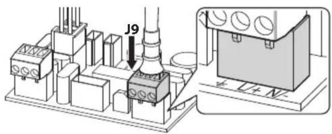
Fig. 20
Fig. 22
커넥터의 유선 단자를 재삽입합니다.
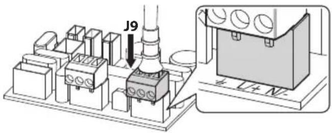
Fig. 23
Fig. 24
커넥터의 유선 단자를 재삽입합니다.
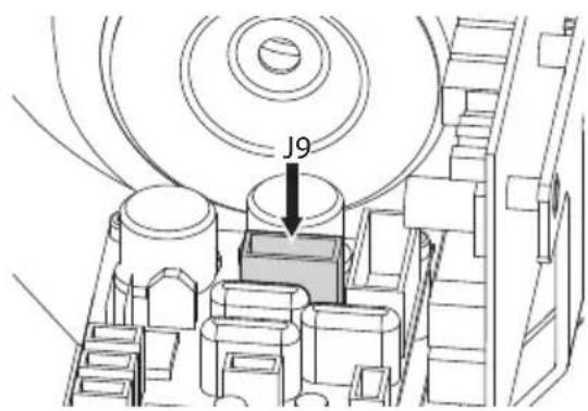
Fig. 25
natural_image
Technical line drawing of a mechanical assembly with no visible text or symbolsFig. 26
Fig. 27
6.10 카메라의 전원공급 연결

natural_image
Technical line drawing of a mechanical assembly with cables and components (no text or symbols)Fig. 31
6.12 광섬유의 연결

natural_image
Technical diagram of an electrical or mechanical assembly with visible wiring and components (no text or labels)Fig. 33
natural_image
Technical diagram of an electrical connector assembly with wiring and components (no text or labels)Fig. 34
| 답-스위치의 형성 (DIP 1) | |||||||||
| 설명 | SW1 | SW2 | SW3 | SW4 | SW5 | SW6 | SW7 | SW8 | 형성 |
| 주소 OFF OFF OFF OFF OFF -- 보류 | |||||||||
| 주소 ON OFF OFF OFF OFF -- 주소 01 | |||||||||
| 주소 OFF ON OFF OFF OFF -- 주소 02 | |||||||||
| 주소 ON ON OFF OFF OFF -- 주소 03 | |||||||||
| ... ... ... ... ... --- ... | |||||||||
| 주소 ON ON ON ON --- 주소 31 | |||||||||
| Baud rate - - - - - ON - - 9600baud (PELCO D), | 38400baud (VIDEOTEC MACRO) | ||||||||
| Baud rate - - - - - OFF - - 2400baud (PELCO D), | 9600baud (VIDEOTEC MACRO) | ||||||||
| 프로토콜 - - - - - - ON - PELCO D | |||||||||
| 프로토콜 | - | - | - | - | - | - | OFF | - | VIDEOTEC MACRO |
| 사전 설치된 모듈 - - - - - - ON SONY | |||||||||
| 사전 설치된 모듈 OFF OFF OFF OFF OFF OFF OFF OFF OFF OFF OFF OFF OFF OFF OFF OFF OFF OFF OFF OFF OFF OFF OFF OFF OFF OFF OFF OFF OFF OFF OFF OFF OFF OFF OFF OFF OFF OFF OFF OFF OFF OFF OFF OFF OFF OFF OFF OFF OFF OFF OFF OFF OFF OFF OFF OFF OFF OFF OFF OFF OFF OFF OFF OFF OFF OFF OFF OFF OFF OFF OFF OFF OFF OFF OFF OFF OFF OFF OFF OFF OFF OFF OFF OFF OFF OFF OFF OFF OFF OFF OFF OFF OFF OFF OFF OFF OFF OFF OFF OFF Off OFF OFF OFF OFF OFF OFF OFF OFF OFF OFF OFF OFF OFF OFF OFF OFF OFF OFF OFF OFF OFF OFF OFF OFF OFF OFF OFF OFF OFF OFF OFF OFF OFF OFF OFF OFF OFF OFF OFF OFF OFF OFF OFF OFF OFF OFF OFF OFF OFF OFF OFF OFF OFF OFF OFF OFF OFF OFF OFF OFF OFF OFF OFF OFF OFF OFF OFF OFF OFF OFF OFF OFF OFF OFF OFF OFF OFF OFF OFF OFF OFF OFF OFF OFF OFF OFF OFF OFF OFF OFF OFF OFF OFF OFF OFF OFF OFF OFF OFF-off-off-off-off-off-off-off-off-off-off-off-off-off-off-off-off-off-off-off-off-off-off-off-off-off-off-off-off-off-off-off-off-off-off-off-off-off-off-off-off-off-off-off-off-off-off-off-off-off-off-off-off-off-off-off-off-off-off-off-off-off-off-off-off-off-off-off-off-off-off-off-off-off-off-off-off-off-off-off-off-off-off-off-off-off-off-off-off-off-off-off-off-off-off-off-off-off-off-off-off-offs-off-off-off-off-off-off-off-off-off-off-off-off-off-off-off-off-off-off-off-off-off-off-off-off-off-off-off-off-off-off-off-off-off-off-off-off-off-off-off-off-off-off-off-off-off-off-off-off-off-off-off-off-off-off-off-off-off-off-off-off-off-off-off-off-off-off-off-off-off-off-off-off-off-off-off-off-off-off-off-off-off-off-off-off-off-off-off-off-off-off-off-off-off-off-off-off-off-off-off-on-off-off-off-off-off-off-off-off-off-off-off-off-off-off-off-off-off-off-off-off-off-off-off-off-off-off-off-off-off-off-off-off-off-off-off-off-off-off-off-off-off-off-off-off-off-off-off-off-off-off-off-off-off-off-off-off-off-off-off-off-off-off-off-off-off-off-off-off-off-off-off-off-off-off-off-off-off-off-off-off-off-off-off-off-off-off-off-off-off-off-off-off-off-off-off-off-off-off-off-foll-off-off-off-off-off-off-off-off-off-off-off-off-off-off-off-off-off-off-off-off-off-off-off-off-off-off-off-off-off-off-off-off-off-off-off-off-off-off-off-off-off-off-off-off-off-off-off-off-off-off-off-off-off-off-off-off-off-off-off-off-off-off-off-off-off-off-off-off-off-off-off-off-off-off-off-off-off-off-off-off-off-off-off-off-off-off-off-off-off-off-off-off-off-off-off-off-off-off-off-white on the right side of the chart. | |||||||||
Ⅱ 12
6.15.1 특별한 명령들
Fig. 40
natural_image
Interior view of an electronic device showing internal components and wiring (no text or symbols visible)Fig. 44

릴레이 작동 사양.
natural_image
Technical illustration of a mechanical assembly with two views: top shows cylindrical components, bottom shows flanged circular components (no text or symbols)Fig. 45

natural_image
Technical line drawing of a mechanical assembly with a cylindrical component and mounting flanges (no text or symbols)Fig. 46
7 켜짐

natural_image
Technical line drawing of a mechanical assembly with concentric components and a directional arrow (no text or symbols)Fig. 47
8.2 각별한 유지관리가
8.2.1 퓨즈의 교체

natural_image
Technical line drawing of a mechanical component with no visible text or symbolsFig. 50
KCs (Employment and labor department 2021-22)
UK Ex (EN IEC 60079-0, EN 60079-1, EN 60079-31)
13기술 도면

측정 단위는 밀리미터로 표시됩니다.
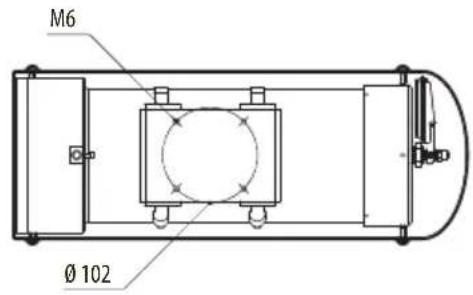
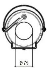
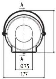
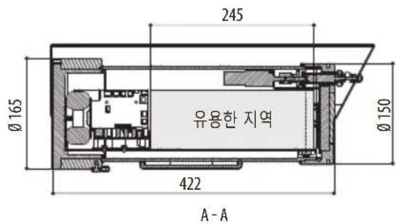

Headquarters Italy VIDEOTEC s.r.l.
Via Friuli, 6 - I-36015 Schio (VI) - Italy
Tel. +39 0445 697411 - Fax +39 0445 697414
Email: info@videotec.com
www.videotec.com
- Contents
- About this manual....7
- Notes on copyright and information on trademarks....7
- Safety rules 7
- Product description and type designation....10
- Preparing the product for use....14
- Installation....14
- Switching on 32
- Maintenance....33
- Cleaning 34
- Information on disposal and recycling 34
- Troubleshooting....35
- Technical data....35
- Technical drawings....38
- About this manual
- Typographical conventions
- DANGER!
- CAUTION!
- INFO
- Underlined titles
- Notes on copyright and information on trademarks
- Safety rules
- Risk of explosion due to electrostatic discharge.
- DANGER! High level hazard. Risk of electric shock. Disconnect the power supply before proceeding with any operation, unless indicated otherwise.
- Product description and type designation
- Product overview
- Range of use
- Specific use conditions
- Gas Group, Dust Group and Temperatures
- Characteristics of installable devices
- Cable entry
- Product marking
- Model identification
- Housing for Day/Night camera
- Housing for thermal camera
- Preparing the product for use
- Unpacking
- Contents
- Safely disposing of packaging material
- Installation
- Installation options
- Parapet mounting
- Bracket mounting
- Fixing the unit to the pole mount adapter or corner mount adapter
- Fixing with pole mount
- Pay attention to the fixing. Tightening torque: 35Nm.
- Fixing with corner adapter
- Sunshield mounting
- Fastening of the wiper blade
- Adjusting the protection grid
- Housing opening
- Before carrying out any type of intervention, read the "Safety rules" chapter of this manual.
- During opening and closure operations of the product, pay attention not to damage the flameproof joint.
- Disconnect J3 and J8 connectors (version with wiper).
- Connector board description
- Description of the connectors board for MHX without wiper
- Description of the connectors board for MHX with wiper and for MHXT
- Description of the CPU board for MHX with wiper and for MHXT
- Earth ground connection
- Earthing equipotential connection
- Connection of the safety earthing
- Connecting the power supply
- Connection of the power supply line in 24Vac and 12Vdc for MHX without wiper
- Connection of the power supply line in 120Vac and 230Vac for MHX without wiper
- Tab. 8
- Connection of the power supply line in 24Vac, 120Vac, 230Vac and 12Vdc for MHX with wiper and for MHXT
- How to install the camera/ lens
- Connection of the camera to the power supply
- Connection of the camera power supply in 24Vac and 12Vdc for MHX without wiper
- Connection of the camera power supply in 120Vac and 230Vac for MHX without wiper
- Connection of the camera power supply in 24Vac, 120Vac, 230Vac and 12Vdc for MHX with wiper and for MHXT
- Camera with analogue video output
- Optical fiber connection
- Use a type of optical fiber suitable for the receiver model installed.
- For further details please refer to the manual of the optical fibre receiver.
- IP camera with digital data transmission
- Connection of the IP camera's RS-485 output
- Serial line connection
- Enabling the wiper
- Enable from the remote button
- Enable from the keyboard
- Enabling the washer (Washer)
- Enable an external illuminator from the day/night camera output
- Housing closure
- Switching on
- Maintenance
- Routine maintenance
- Inspecting the cables
- Replacing the gasket
- Extraordinary maintenance
- Fuses replacement
- Cleaning
- Cleaning the glass window
- Cleaning the germanium window
- Cleaning the product
- Information on disposal and recycling
- Troubleshooting
- PROBLEM The product does not go on.
- PROBLEM The wiper is frozen and unresponsive to commands.
- Technical data
- MAXIMUS MHX
- General
- Mechanical
- Electrical
- Serial communications
- I/O
- Cameras
- Environment
- Certifications
- Certifications - Explosion-proof applications
- MAXIMUS MHXT
- General
- Mechanical
- Housing's window
- Electrical
- Serial communications
- Cameras
- Environment
- Certifications
- Certifications - Explosion-proof applications
- Technical drawings
- MAXIMUS MHX, MAXIMUS MHXT
- Sommario
- Accensione
- Generale
- Disegni tecnici
- Sommaire
- Allumage
- Entretien extraordinaire
- Généralités
- Certifications - Applications anti-déflagrations
- Dessins techniques
- Inhaltsverzeichnis
- Allgemeines....7
- Einschaltung
- Abb. 50
- Allgemeines
- Включение
- Sumário
- Fixação do teto
- Acendimento
- Geral
- 요약
- 설명서에 있는 정보들 7
- 12기술데이터 35
- 선실드 장착
- 와이퍼의 브러시 고정
- 보호 그리드의 조절
- 6.5하우징 열기
- 6.7.2안전 접지의 접속
- 카메라의 전원공급 연결
- 광섬유의 연결
- 켜짐
- 각별한 유지관리가
- 퓨즈의 교체
- 13기술 도면
Brand : Videotec
Model : Maximus MHX
Category : Surveillance Camera