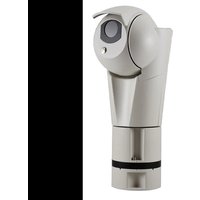
ULISSE EVO THERMAL - Surveillance Camera Videotec - Free user manual and instructions
Find the device manual for free ULISSE EVO THERMAL Videotec in PDF.


| Product type | Outdoor thermal PTZ camera |
| Brand | Videotec |
| Model | ULISSE EVO THERMAL (UET) |
| Dimensions (L x W x H) | 406 x 318 x 438 mm |
| Net weight | 7,1 kg |
| Power supply | 24 Vac ±20%, 24 Vdc ±10%, PoE 90 W (IEEE 802.3bt Class 8) |
| Power consumption | 21 W (stationary, ECO-MODE) to 57 W (peak at startup with heating) |
| Thermal sensor type | Uncooled VOx microbolometer, 336x256 or 640x512 pixels |
| Thermal resolution | Up to 720x480 interpolated |
| Horizontal field of view | From 9.3° to 69° depending on lens |
| Pan rotation | 360° continuous |
| Tilt rotation | -90° to +90° (up to -40° to +90° in ceiling mount) |
| Rotation speed | 0.1°/s to 250°/s |
| Preset accuracy | 0.05° |
| PTZ functions | Preset, Preset Tour, Autoflip, Autopan, 250 presets max |
| Radiometric analysis | On 4 central pixels or defined zone (advanced), temperature alarm |
| Alarm inputs/outputs | 2 inputs (12-18 Vdc), 2 relay outputs (1 A, 30 Vac/Vdc) |
| Network connectivity | Ethernet 100 Base-TX, ONVIF Profile Q/S/T, HTTPS, IPv4/IPv6 |
| Protection rating | IP66, IP67, IP68 |
| Impact resistance | IK10 (except germanium window) |
| Operating temperature | -40°C to +65°C (continuous) |
| Wind resistance | Up to 230 km/h |
| Housing material | Aluminum casting and technopolymer, epoxy-polyester paint |
| Optical window | Germanium, thickness 1.5 mm, scratch-resistant DLC coating |
| Certifications | CE, cULus, EAC, EN50121-4 railway, Lloyd's Marine Type Approval |
| Maintenance | Clean window with neutral soap, replace wiper blade, check cables |
| Repairability | Original VIDEOTEC spare parts, technical support with serial number |
Frequently Asked Questions - ULISSE EVO THERMAL Videotec
User questions about ULISSE EVO THERMAL Videotec
0 question about this device. Answer the ones you know or ask your own.
Ask a new question about this device
Download the instructions for your Surveillance Camera in PDF format for free! Find your manual ULISSE EVO THERMAL - Videotec and take your electronic device back in hand. On this page are published all the documents necessary for the use of your device. ULISSE EVO THERMAL by Videotec.
USER MANUAL ULISSE EVO THERMAL Videotec
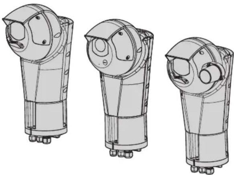
PTZ camera with high performance and extreme reliability
natural_image
Technical line drawings of three mechanical components with mounting holes and internal cavities (no text or symbols)EN English - Instruction manual
IT Italiano - Manuale di istruzioni
FR Français - Manuel d'instructions
DE Deutsch - Bedienungsanleitung
RU Русский - Руководство по эксплуатации
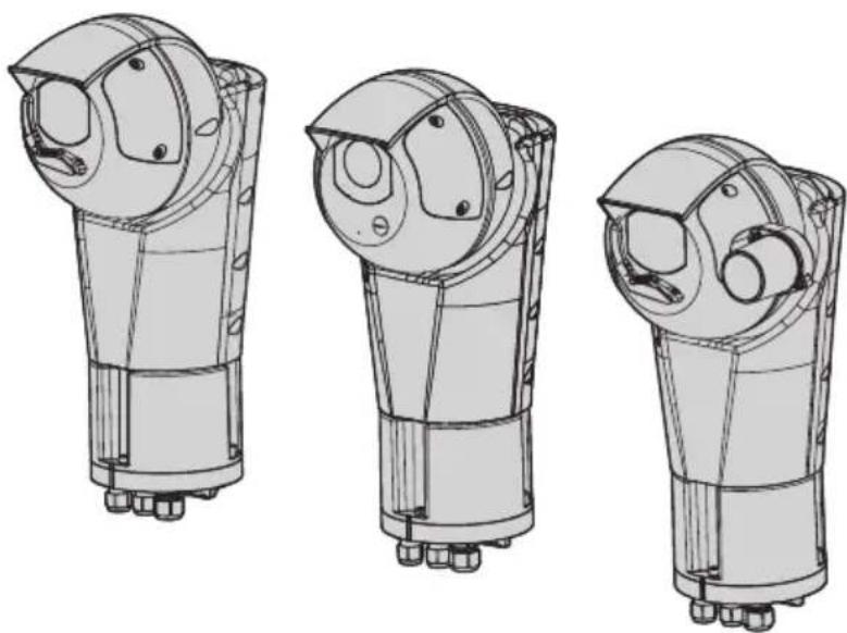
ULISSE EVO (UE)
ULISSE EVO THERMAL (UET)
ULISSE EVO DUAL (UED)
PTZ camera with high performance and extreme reliability
natural_image
Technical line drawings of three mechanical components with mounting holes and internal cavities (no text or symbols)Contents
1 About this manual....7
1.1 Typographical conventions....7
2 Notes on copyright and information on trademarks....7
3 Safety rules ....7
4 Product description and type designation....10
4.1 Product overview .... 10
4.2 Product marking label....10
4.3 Model identification.... 11
5 Preparing the product for use....13
5.1 Safety precautions before use.... 13
5.2 Unpacking....13
5.3 Contents 13
5.4 Safely disposing of packaging material.... 13
6 Installation....14
6.1 Installation options....14
6.1.1 Viewing angles....14
6.1.2 Installation with internal cable passage....15
6.1.3 Installation with internal cable passage with product inverted 16
6.1.4 Installation with quick connectors .... 17
6.1.5 Installation with quick connectors with product inverted....18
6.1.6 Typical connection of accessories....19
6.2 Opening the base of the product 20
6.3 Mounting the bracket 20
6.4 Cable management....21
6.5 Fixing the base to the support....22
6.6 Sunshield mounting 22
6.7 Fastening of the safety coupling....22
6.8 Connector board description....23
6.9 Connecting the power supply 24
6.9.1 24Vac/24Vdc power supply ....24
6.9.2 PoE 90W power supply 25
6.9.2.1 PoH backward compatibility mode enabling 25
6.10 Alarms and relays connections....25
6.11 Ethernet cable connection 26
6.12 Installation of the upper body 27
7 Switching on 28
8 Configuration....29
8.1 Default IP address 29
8.2 Web interface 29
8.2.1 First access to the web pages....29
9 Accessories and Supports....29
10 Instructions for normal operation....29
11 Maintenance 30
11.1 Routine maintenance....30
11.1.1 Inspecting the cables 30
11.1.2 Replacement of the wiper blade ....30
11.2 Extraordinary maintenance....30
11.2.1 Reset to Factory Default Settings....30
12 Cleaning 31
12.1 Cleaning the window and external surfaces of the product 31
12.1.1 Cleaning the germanium window 31
13 Information on disposal and recycling 32
14 Troubleshooting....32
15 Technical data....33
15.1 ULISSE EVO (UE) 33
15.1.1 General....33
15.1.2 Mechanical....33
15.1.3 Electrical....33
15.1.4 Network....34
15.1.5 Cybersecurity 34
15.1.6 Video 34
15.1.7 Video analytics 34
15.1.8 Cameras....35
15.1.9 Illuminators....36
15.1.10 Environment....36
15.1.11 Certifications 36
15.1.12 Certifications - Railway applications 36
15.1.13 Certifications - Marine applications....36
15.2 ULISSE EVO THERMAL (UET)....37
15.2.1 General 37
15.2.2 Mechanical 37
15.2.3 Housing's window 37
15.2.4 Electrical 38
15.2.5 Network....38
15.2.6 Cybersecurity....38
15.2.7 Video....38
15.2.8 Cameras....39
15.2.9 Environment 41
15.2.10 Certifications....41
15.2.11 Certifications - Railway applications....41
15.2.12 Certifications - Marine applications....41
15.3 ULISSE EVO DUAL (UED) 42
15.3.1 General 42
15.3.2 Mechanical 42
15.3.3 Housing's window 42
15.3.4 Electrical 42
15.3.5 Network....43
15.3.6 Cybersecurity....43
15.3.7 Video....43
15.3.8 Day/Night cameras....44
15.3.9 Thermal Cameras 45
15.3.10 Environment 46
15.3.11 Certifications....46
15.3.12 Certifications - Railway applications....46
16 Technical drawings....47
1 About this manual
Read all the documentation supplied carefully before installing and using this product. Keep the manual in a convenient place for future reference.
1.1 Typographical conventions

DANGER!
High level hazard.
Risk of electric shock. Disconnect the power supply before proceeding with any operation, unless indicated otherwise.

DANGER!
Mechanical hazard.
Risk of crushing or shearing.

CAUTION!
Medium level hazard.
This operation is very important for the system to function properly. Please read the procedure described very carefully and carry it out as instructed.

INFO
Description of system specifications.
We recommend reading this part carefully in order to understand the subsequent stages.
2 Notes on copyright and information on trademarks
The mentioned names of products or companies are trademarks or registered trademarks.
Microsoft Edge ^® , Windows XP ^® , Windows Vista ^® , Windows 7 ^® , Windows 8 ^® , Windows 10 ^® are the property of Microsoft Corporation.
INTEL ^® Core ^™ 2 Duo, INTEL ^® Core ^™ 2 Quad, INTEL ^® Xeon ^® are the property of Intel Corporation.
ONVIF ^® is a trademark of Onvif, Inc.
3 Safety rules

CAUTION! Hazardous moving parts. Keep fingers and other body parts away.

CAUTION! Device installation and maintaining must be performed by specialist technical staff only.

CAUTION! TNV-1 installation type. The installation is type TNV-1, do not connect it to SELV circuits.

CAUTION! In order to reduce the risk of fire, only use UL Listed or CSA certified cables with sections greater than or equal to 0.14mm ^2 (26AWG).

CAUTION! The infrared LED illuminator emits high-intensity invisible light. For further details on configuration and use, refer to the illuminator accessory manual.

CAUTION! The white LED illuminator emits high intensity light. For further details on configuration and use, refer to the illuminator accessory manual.

During normal operation the surface of the illuminator can reach high temperatures. Do not allow direct contact and position the appliance where it is inaccessible to unauthorised persons. Before touching, switch off the illuminator and allow to cool for a minimum period of 10 minutes.
- The manufacturer declines all responsibility for any damage caused by an improper use of the appliances mentioned in this manual. Furthermore, the manufacturer reserves the right to modify its contents without any prior notice. The documentation contained in this manual has been collected and verified with great care. The manufacturer, however, cannot take any liability for its use. The same thing can be said for any person or company involved in the creation and production of this manual.
- The equipment is intended for installation in a Restricted Access Area by specialist technical staff.
- Before starting any operation, make sure the power supply is disconnected.
- Be careful not to use cables that seem worn or old.
- Never, under any circumstances, make any changes or connections that are not shown in this handbook. Improper use of the appliance can cause serious hazards, risking the safety of personnel and of the installation.
-
Use only original spare parts. Non-original spare parts could cause fire, electrical discharge or other hazards.
-
Before proceeding with installation, check the supplied material to make sure it corresponds to the order specification by examining the identification labels (4.2 Product marking label, page 10).
- This device was designed to be permanently secured and connected on a building or on a suitable structure. The device must be permanently secured and connected before any operation.
- Use a Class 2 listed UL tranformer, compliant with the Standards in force, only for products marked UL, powered at 24Vac.
- In the case of a 24Vac power supply, you must provide for adequate separation from the AC power supply line using double or reinforced insulation between the main power supply line and the secondary circuit.
- A power disconnect device must be included in the electrical installation, and it must be very quickly recognizable and operated if needed.
-
The separate protective earthing terminal provided on this product shall be permanently connected to earth.
-
This is a Class A product. In a domestic environment this product may cause radio interference. In this case the user may be required to take adequate measures.
- Connect the device to a power source corresponding to the indications given on the marking label. Before proceeding with installation make sure that the power line is properly isolated. The power supply voltage must not exceed the limits: 24Vac ±20%, 24Vdc ±10%.
- If it is necessary to transport the device, this should be done with great care. Abrupt stops, bumps and violent impact could damage the unit or injure the user.
- To comply with the main supply voltage dips and short interruption requirements, use a suitable Uninterruptible Power Supply (UPS) to power the unit.
- The Cat5e/Cat6 shielded (STP) Ethernet cable is required to fully comply with EMC regulatory standards.
- To meet the requirements of the EN 50121-4 Railway Applications Standard, use an external power supply or PoE injector that is also compliant with EN 50121-4.
-
The appliance includes moving parts. Make sure that the unit is positioned where it is inaccessible under normal operating conditions.
-
Attach the Dangerous Moving Parts label near the device. (Fig. 3, page 13).
- Do not use the appliance in the presence of flammable substances.
- Do not allow children or unauthorised people to use the appliance.
- The device can only be considered to be switched off when the power supply has been disconnected and the connection cables to other devices have been removed.
- Only skilled personnel should carry out maintenance on the device. When carrying out maintenance, the operator is exposed to the risk of electrocution and other hazards.
- Use only the accessories indicated by the manufacturer. Any change that is not expressly approved by the manufacturer will invalidate the warranty.
• Take all necessary precautions to prevent the apparatus from being damaged by electrostatic discharge. - The unit has been made for connection using a three-core cable. To make a correct connection to the earth circuit, follow the instructions in this handbook.
- Handle the unit with great care, high mechanical stress could damage it.
4 Product description and type designation
The PTZ ULISSE EVO video camera is ideal as a video surveillance solution for outdoor applications in urban centres, critical infrastructures, traffic and railways. It was designed to guarantee complete reliability and continuous operation in more difficult external environments and offer exceptional strength against corrosion and a vast range of temperatures.
4.1 Product overview
The product consists of 3 parts:
- Sunshield.
- Body.
- Base.
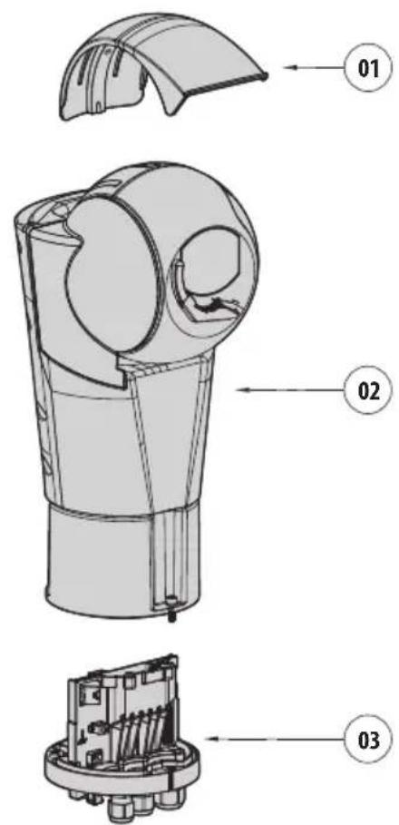
Fig. 1
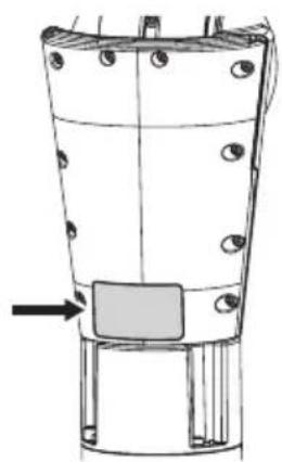
4.2 Product marking label

Before proceeding further with installation, make sure the material supplied corresponds to the order specification by examining the marking labels.

The product has a label applied in compliance with CE marking.
natural_image
Technical line drawing of a mechanical component with mounting holes and a highlighted section (no text or symbols)Fig. 2
The label shows:
- Model identification code.
• Supply voltage (Volt).
• Frequency (Hertz).
• Current consumption (Ampere). - Protection degree (IP).
- Serial number.
4.3 Model identification
| ULISSE EVO (UE) - CONFIGURATION OPTIONS | |||||
| Voltage | Camera | Colour | Video analytics | Revision | |
| UE | 2 24Vac, 24Vdc, PoE 90W | 1 Super low-light Day/Night camera, FULL HD 1080p, 30x, with DELUX technology | A Grey-white (RAL9002) | 000 Without integrated video analytics (without VIDEOTEC ANALY TICS) | A Complies with ONVIF, Profile Q, Profile S and Profile T |
| 2 SONY FCB-EV7520 camera, FULL HD 1080p, 30x | F Black (RAL9005) | V00 With integrated video analytics (VIDEOTEC ANALY TICS) | J Complies with ONVIF, Profile S and Profile T | ||
Tab. 1
| ULISSE EVO THERMAL (UET) - CONFIGURATION OPTIONS | ||||||
| Voltage | Camera | Colour | Radiometry | Revision | Frequency | |
| UET | 2 24Vac, 24Vdc, PoE 90W | I 9.3° HFOV, Thermal camera 35mm, 336x256 | A Grey-white (RAL9002) | 000 Thermal camera with radiometric functions | A | - 75Hz |
| L 13° HFOV, Thermal camera 25mm, 336x256 | F Black (RAL9005) | 0R0 Thermal camera with advanced radiometric functions | H 30Hz | |||
| Z 17° HFOV, Thermal camera 19mm, 336x256 | ||||||
| M 25° HFOV, Thermal camera 13mm, 336x256 | ||||||
| Q 35° HFOV, Thermal camera 9mm, 336x256 | ||||||
| D 18° HFOV, Thermal camera 35mm, 640x512 | ||||||
| E 25° HFOV, Thermal camera 25mm, 640x512 | ||||||
| U 32° HFOV, Thermal camera 19mm, 640x512 | ||||||
| G 45° HFOV, Thermal camera 13mm, 640x512 | ||||||
| H 69° HFOV, Thermal camera 9mm, 640x512 | ||||||
Tab. 2
EN - English - Instruction manual
| ULISSE EVO DUAL (UED) - CONFIGURATION OPTIONS | |||||||
| Voltage Day/Night camera | Thermal camera Colour | Revision Frequency | |||||
| UED 2 | 24Vac, 24Vdc, PoE90W | 2 SONY FCB-EV7520camera, FULL HD1080p, 30x | C 34° HFOV, Thermal camera 6.3mm,320x256 | A Grey-white(RAL9002) | 000 A | Complies withONVIF, ProfileQ, Profile S andProfile T | - 7.5Hz |
| D 24° HFOV, Thermal camera 9.1mm,320x256 | J Complies withONVIF, Profile Sand Profile T | H 30Hz | |||||
| F 12° HFOV, Thermal camera 18mm,320x256 | |||||||
| I 50° HFOV, Thermal camera 8.7mm,640x512 | |||||||
| L 32° HFOV, Thermal camera 14mm,640x512 | |||||||
| N 18° HFOV, Thermal camera 24.4mm,640x512 | |||||||
Tab. 3
5 Preparing the product for use

Any change that is not expressly approved by the manufacturer will invalidate the warranty.
5.1 Safety precautions before use

The appliance includes moving parts. Make sure that the unit is positioned where it is inaccessible under normal operating conditions. Attach the warning label supplied with the appliance, placing it near the unit so that it can be seen easily.
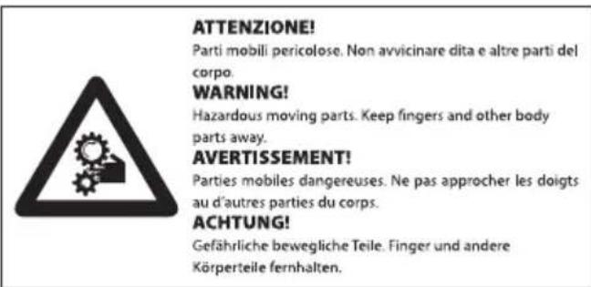
Fig. 3
5.2 Unpacking

A thin oil film due to the gasket may be present on the unit. This oil film does not alter the mechanical performance of the unit. Refer to the cleaning instructions in the relevant chapter (12 Cleaning, page 31).
When the product is delivered, make sure that the package is intact and that there are no signs that it has been dropped or scratched.
If there are obvious signs of damage, contact the supplier immediately.
When returning a faulty product we recommend using the original packaging for shipping.
Keep the packaging in case you need to send the product for repairs.
5.3 Contents
Check the contents to make sure they correspond with the list of materials as below:
- Positioning unit
-
Sunshield
• Accessories package: -
Allen wrench
- Power connector
- I/O connector
- Label (CAUTION: Hazardous moving parts)
- Reduction gasket, for alarm cable, for cable glands M16
- Reduction gasket, for Ethernet cable with pre-assembled connector, for cable gland M20
- Instruction manual
- Plate for safety chain coupling
- Screw for sunshield fastening
5.4 Safely disposing of packaging material
The packaging material can all be recycled. The installer technician will be responsible for separating the material for disposal, and in any case for compliance with the legislation in force where the device is to be used.
6 Installation

Never, under any circumstances, make any changes or connections that are not shown in this handbook. Failure to follow the connection instructions that are given in the handbook may create serious safety hazards for people and for the installation.

Do not change the wiring in the product as it is supplied to you. Failure to follow this instruction may create serious safety hazards for people and for the installation, and will also invalidate the warranty.

The product can be powered in 24Vac/24Vdc or via PoE 90W.

Keep the connection diagram for future reference.
6.1 Installation options
The product can be installed in various modes using the supports and various adaptors available, meeting every installation requirement.
6.1.1 Viewing angles
The figure displays the viewing angles of the tilt in the two installation modes (upright or inverted).
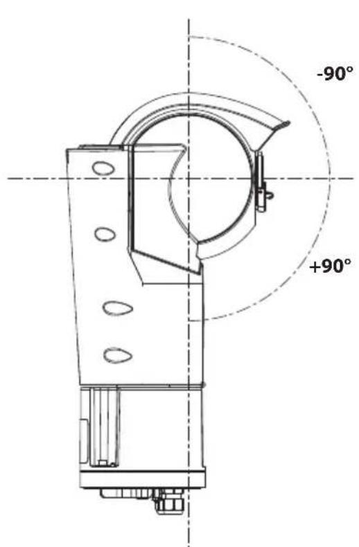
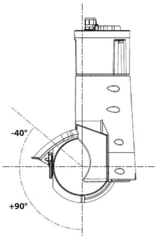
Fig. 4
6.1.2 Installation with internal cable passage
This installation mode allows cable passage inside the mounting brackets.
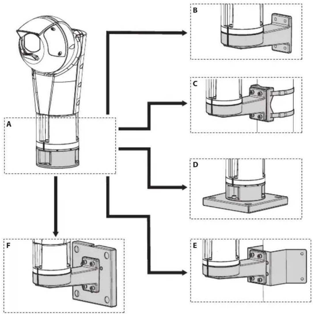
flowchart
graph TD
    A["Component A"] --> B["Step B"]
    A --> C["Step C"]
    A --> D["Step D"]
    A --> E["Step E"]
    F["Component F"] --> B
    F --> C
    F --> D
    F --> E
Fig. 5
6.1.3 Installation with internal cable passage with product inverted

CAUTION! Always secure the product with the safety chain (6.7 Fastening of the safety coupling, page 22).
This installation mode allows cable passage inside the mounting brackets.
In the event of installation of the product inverted, the sunshield must be assembled as illustrated in the relevant chapter (6.6 Sunshield mounting, page 22) and enable the Ceiling Mount mode using the web interface.
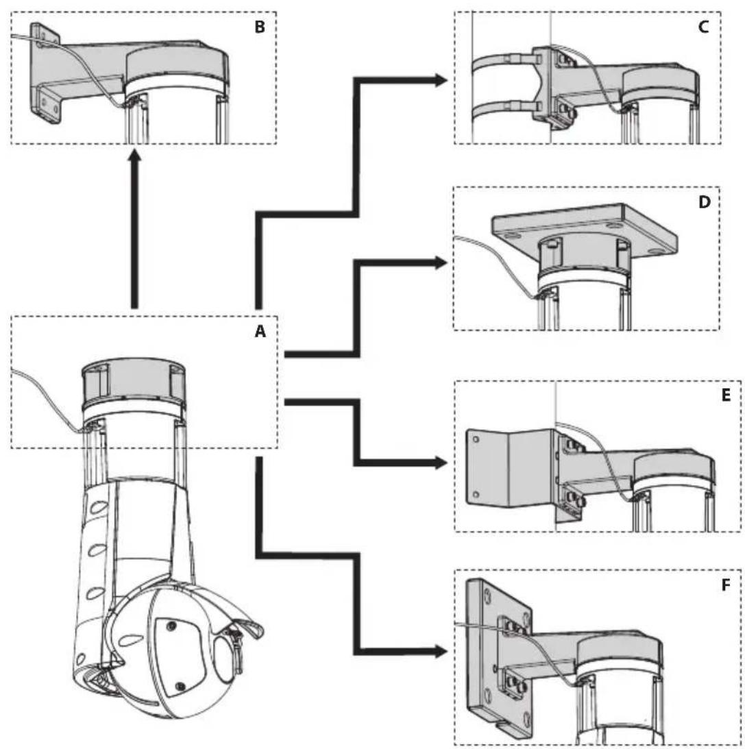
flowchart
graph TD
    A["Sensor A"] --> B["Component B"]
    B --> C["Sensor C"]
    A --> D["Sensor D"]
    D --> E["Sensor E"]
    A --> F["Sensor F"]
    F --> E
    style A fill:#f9f,stroke:#333
    style B fill:#ccf,stroke:#333
    style C fill:#cfc,stroke:#333
    style D fill:#fcc,stroke:#333
    style E fill:#cff,stroke:#333
    style F fill:#ffc,stroke:#333
Fig. 6
6.1.4 Installation with quick connectors
This installation mode with the quick connectors allows easy and fast replacement of the unit.
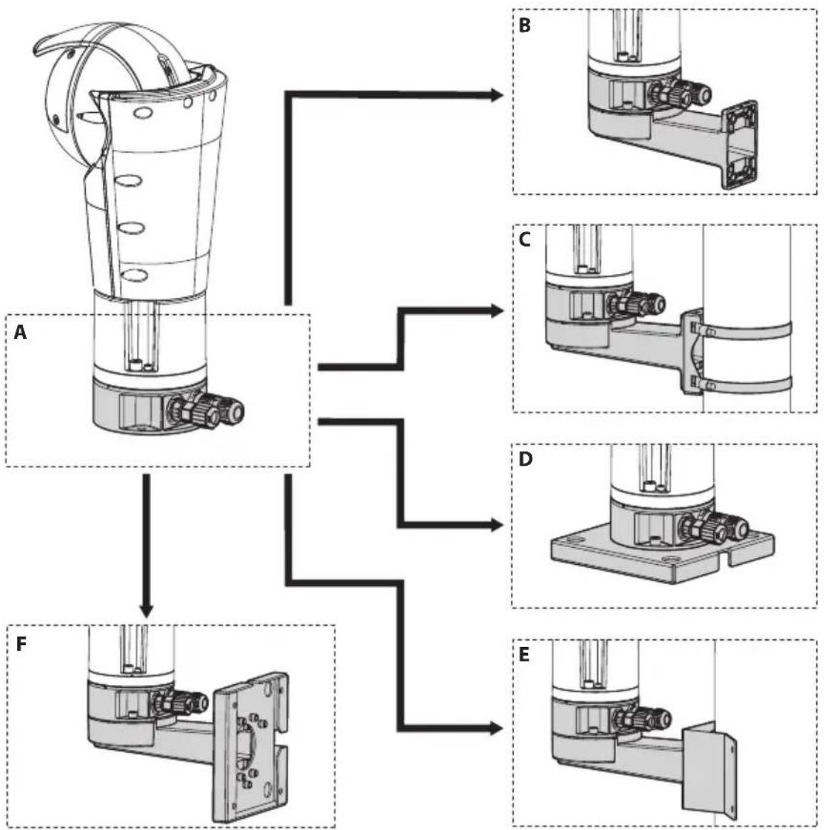
flowchart
graph TD
    A["Component A"] --> B["B"]
    A --> C["C"]
    A --> D["D"]
    A --> E["E"]
    F["Component F"] --> B
    F --> C
    F --> D
    F --> E
Fig. 7
6.1.5 Installation with quick connectors with product inverted

CAUTION! Always secure the product with the safety chain (6.7 Fastening of the safety coupling, page 22).
This installation mode with the quick connectors allows easy and fast replacement of the unit.
In the event of installation of the product inverted, the sunshield must be assembled as illustrated in the relevant chapter (6.6 Sunshield mounting, page 22) and enable the Ceiling Mount mode using the web interface.
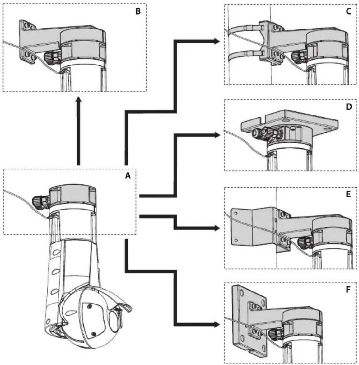
flowchart
graph TD
    A["Component A"] --> B["Component B"]
    B --> C["Component C"]
    A --> D["Component D"]
    D --> E["Component E"]
    A --> F["Component F"]
    F --> E
    style A fill:#f9f,stroke:#333
    style B fill:#ccf,stroke:#333
    style C fill:#cfc,stroke:#333
    style D fill:#fcc,stroke:#333
    style E fill:#cff,stroke:#333
    style F fill:#ffc,stroke:#333
Fig. 8
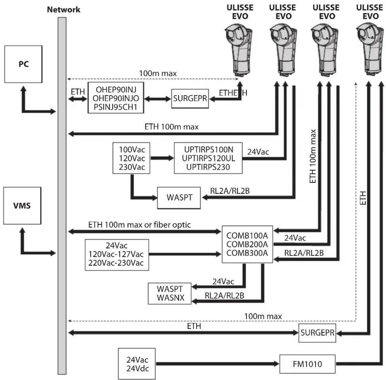
6.1.6 Typical connection of accessories
The figure displays how the accessories can be connected to the product.
flowchart
graph TD
    A["PC"] --> B["Network"]
    C["VMS"] --> B
    B --> D["OHEP90INJ OHEP90INJO PSINJ95CH1"]
    D --> E["SURGEPR"]
    E --> F["ULISSE EVO"]
    E --> G["ULISSE EVO"]
    E --> H["ULISSE EVO"]
    B --> I["100Vac 120Vac 230Vac"]
    I --> J["UPTIRPS100N UPTIRPS120UL UPTIRPS230"]
    J --> K["WASPT"]
    K --> L["COMB100A COMB200A COMB300A"]
    L --> M["24Vac 120Vac-127Vac 220Vac-230Vac"]
    L --> N["WASPT WASNX"]
    N --> O["FM1010"]
    O --> P["SURGEPR"]
    P --> Q["24Vac 24Vdc"]
    Q --> R["ETH 100m max or fiber optic"]
    R --> S["ETH 100m max"]
    S --> T["ETH 100m max"]
    T --> U["ETH 100m max"]
    U --> V["ETH 100m max"]
    V --> W["ULISSE EVO"]
    V --> X["ULISSE EVO"]
    V --> Y["ULISSE EVO"]
    V --> Z["ULISSE EVO"]
    style A fill:#f9f,stroke:#333
    style C fill:#f9f,stroke:#333
    style B fill:#ccf,stroke:#333
    style D fill:#cfc,stroke:#333
    style E fill:#fcc,stroke:#333
    style J fill:#cff,stroke:#333
    style L fill:#ffc,stroke:#333
    style K fill:#fcf,stroke:#333
    style M fill:#cff,stroke:#333
    style N fill:#cff,stroke:#333
    style O fill:#ffc,stroke:#333
    style Q fill:#cff,stroke:#333
    style R fill:#ffc,stroke:#333
    style S fill:#ffc,stroke:#333
    style T fill:#ffc,stroke:#333
    style U fill:#ffc,stroke:#333
    style V fill:#ffc,stroke:#333
    style W fill:#ffc,stroke:#333
Fig. 9
The power supply cables must be appropriately dimensioned. 0.75mm ^2 (18AWG) or heavier wire is recommended for most cable runs between the 24Vac/24Vdc power source and the camera (15 Technical data, page 33). If a longer cable run is required, a wire gauge table should be consulted to ensure that the voltage at the camera does not drop outside of the specified range when the camera is operating at the maximum rated power draw.
The SURGEPR and FM1010 accessories must be installed close to the PTZ camera.
6.2 Opening the base of the product
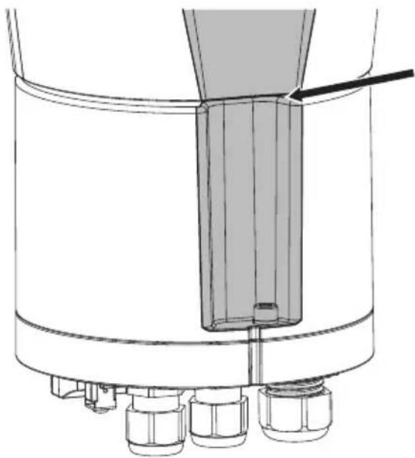
To avoid scratching the product with the hexagonal wrench, align the groove on the body of the product with the screw before screwing it in.
natural_image
Technical line drawing of a mechanical component with no visible text or symbolsFig. 10
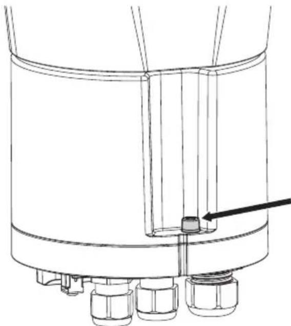
Unscrew the three screws at the bottom of the product (Fig. 11, page 20).
natural_image
Technical line drawing of a cylindrical mechanical component with a small inset showing a small component, no text or symbols present.Fig. 11
6.3 Mounting the bracket

Take special care when attaching and fastening down the apparatus. If the equipment must be fastened to a concrete surface, plugs must be used with a minimum traction force of 300dN each. For a metal surface use screws with a diameter of at least 8mm and of an appropriate length. The fastening system must be capable of supporting at least 4 times the weight of the entire equipment (PTZ camera, supports and adapters).

The device should be assembled vertically. Any other position could impair the performance of the device.
Various types of optional mounts and accessories are available (9 Accessories and Supports, page 29).
Choose the mounting accessories for the installation you want to implement (6.1 Installation options, page 14).
Install the optional mounts and accessories by following the instruction manuals provided with the bracket or accessory.
6.4 Cable management

The cables must be adequately fastened to the structure to avoid causing the cables to be accidentally unplugged.

You must use cables suited to the type of installation you are using.

Nominal section of the cables used: consult the technical data in the relevant chapter (15 Technical data, page 33).
Insert the cables into the cable glands.
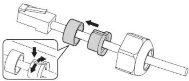
If the cable has a pre-assembled connector, replace the gasket inside the cable gland with the one supplied. Insert the Ethernet cable in the gasket as illustrated in the figure (Fig. 12, page 21). Pass the cable with connector RJ45 through the M20 cable gland.
natural_image
Mechanical assembly diagram showing a shaft and housing with directional arrows indicating motion (no text or symbols)Fig. 12
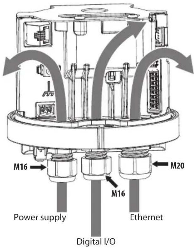
Fig. 13
Tighten the cable glands.

Pay attention to the fixing. Tightening torque: 1.5Nm (±0.2Nm) for M16 cable glands, 2Nm (±0.2Nm) for M20 cable glands.
If a cable gland does not have a cable inserted, a specific cap must be inserted for closure. Always close the cable glands with the stated tightening torque.
6.5 Fixing the base to the support

For further details on configuration and use, refer to the manual of the relevant accessory or support.
6.6 Sunshield mounting
You can fix the sunshield to the housing using the screws supplied.

Pay attention to the fixing. Tightening torque: 1.6Nm (±0.2Nm).
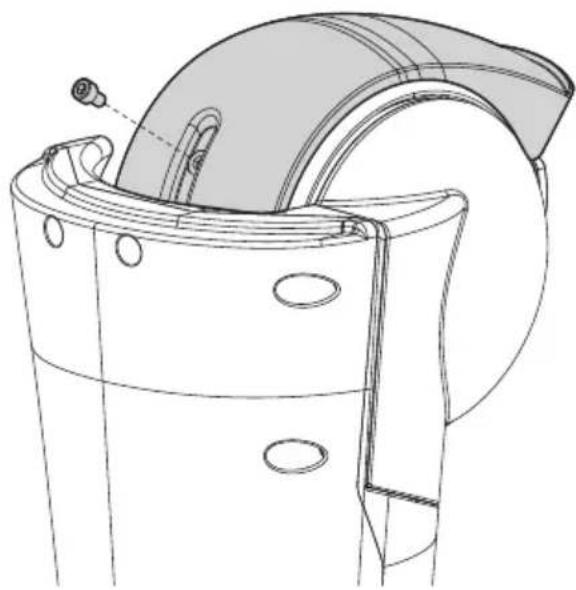
natural_image
Technical line drawing of a mechanical component with no visible text or symbolsFig. 14 Upright installation of the product.
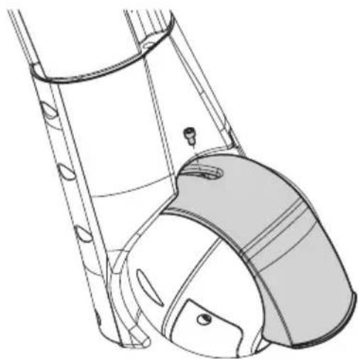
natural_image
Technical line drawing of a mechanical component with no visible text or symbolsFig. 15 Installation of the product inverted.
6.7 Fastening of the safety coupling

Take special care when attaching and fastening down the apparatus. If the equipment must be fastened to a concrete surface, plugs must be used with a minimum traction force of 300dN each. For a metal surface use screws with a diameter of at least 8mm and of an appropriate length. The fastening system must be capable of supporting at least 4 times the weight of the entire equipment (PTZ camera, supports and adapters).
The product is equipped with a safety coupling to secure the product to a second fixing point through a safety chain or cable.
Position the safety coupling and fix it with the screw and the washer supplied as shown in the figure.

Use an external anchor point to fix the chain or the safety cable to the unit support surface. Choose a chain or safety cable capable of supporting 4 times the weight of the unit, including its brackets and adaptors.

Pay attention to the fixing. Tightening torque: 4.5Nm (±0.2Nm).

Apply thread-locker into the holes for screws (Loctite 243®).
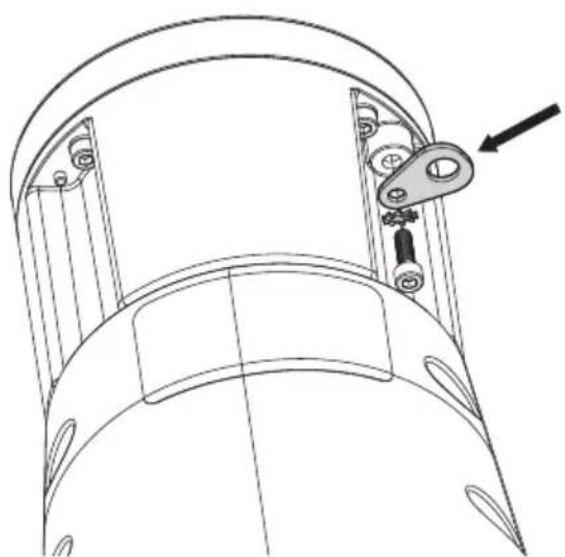
natural_image
Technical line drawing of a mechanical component with an arrow indicating direction (no text or symbols present)Fig. 16
6.8 Connector board description

The earth ground cable must always be connected to the relevant terminal (GND_INT or GND_EXT, Fig. 17, page 23).
| BOARD DESCRIPTION | |
| Connector Function | |
| J3 Ethernet | |
| J4 Power supply | |
| J6 Digital I/O | |
| S1, S2 Reset to F | Factory Default Settings. PoHbackward compatibility mode enabling. |
| GND_INT (internal earth ground terminal) | Ground connection. 24Vac/24Vdc power supply |
| GND_EXT (external earth ground terminal) | Ground connection. PoE 90W power supply |
Tab. 4
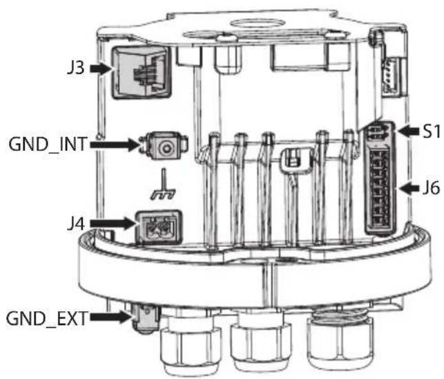
Fig. 17
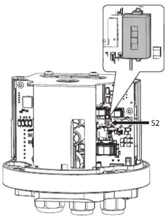
Fig. 18
6.9 Connecting the power supply
6.9.1 24Vac/24Vdc power supply

Electrical connections must be performed with the power supply disconnected and the circuit-breaker open.

When commencing installation make sure that the specifications for the power supply for the installation correspond with those required by the device.

Do not power the product using auto-transformers.

Check that the power supply socket and cable are adequately dimensioned.

Nominal section of the cables used: consult the technical data in the relevant chapter (15 Technical data, page 33).

In the case of a direct current power supply, the polarity of the voltage applied to the power supply terminal is irrelevant.
To power the unit, use the power supply units indicated in the technical data sheet of the product on the website: www.videotec.com, or use a toroidal transformer with nominal power of at least 200VA.
Connect the power supply cable to the relative connector (J4, Fig. 19, page 24).
Connect the ground cable to the relevant terminal (GND_INT, Fig. 19, page 24).
The power cables must be sized according to the ratio between the supply current and the distance to be covered.
If the product is powered by two sources of power simultaneously (24V and PoE 90W), only the 24V line will be used, disabling the PoE 90W power supply.
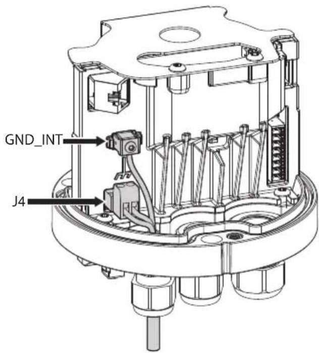
Fig. 19
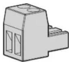
The removable connector is supplied in the kit.
natural_image
Technical drawing of a mechanical connector or bracket (no text or symbols)Fig. 20
6.9.2 PoE 90W power supply
The product can be powered by 90W PoE according to standard IEEE 802.3bt (CLASS 8) or via a PoH power injector.
The PoE injector must have at least 90W power.
By default, the product is configured to work according to standard IEEE 802.3bt.
ThePoH backward compatibility mode must be enabled with the following power injector.
• VIDEOTEC injector OHEP90INJ.
• VIDEOTEC injector OHEP90INJO.
As described in the VIDEOTEC PSINJ95CH1 accessory manual, depending on the position of the PoE Mode switch, the injector can operate in different ways:
• IEEE802.3bt (Standard position).
- PoH (Legacy position).
If the product is powered by two sources of power simultaneously (24V and PoE 90W), only the 24V line will be used, disabling the PoE 90W power supply.
A list of tested power injectors is available upon request.
6.9.2.1 PoH backward compatibility mode enabling
There are two DIP switches on the connector board which allow the PoH backward compatibility mode to be enabled (S1, S2, Fig. 17, page 23 and Fig. 18, page 23).
| SELECTING THE UNIT OPERATING MODE (S1, S2) | ||||
| Function | S1 | S2 | Description | |
| DIP 1 DIP 2 | DIP 1 - | |||
| PoH backward compatibility | - ON ON Enabled | |||
| - OFF OFF Disabled | ||||
Tab. 5
6.10 Alarms and relays connections

Nominal section of the cables used: consult the technical data in the relevant chapter (15 Technical data, page 33).

Maximum relay voltage and current: consult the technical data in the relevant chapter (15 Technical data, page 33).
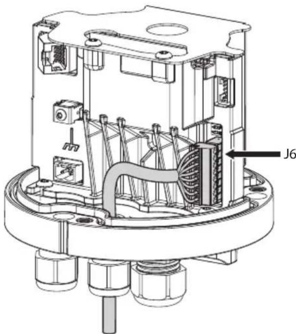
Connect the digital I/O cable to the relative connector (J6, Fig. 21, page 25).
The maximum cable length for each alarm is 200m.
natural_image
Technical diagram of a mechanical assembly with internal components and labeled part J6 (no readable text or symbols beyond label)Fig. 21
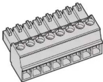
The removable connector is supplied in the kit.
natural_image
Technical illustration of a multi-pin electrical connector with multiple slots and mounting holes (no text or symbols)Fig. 22
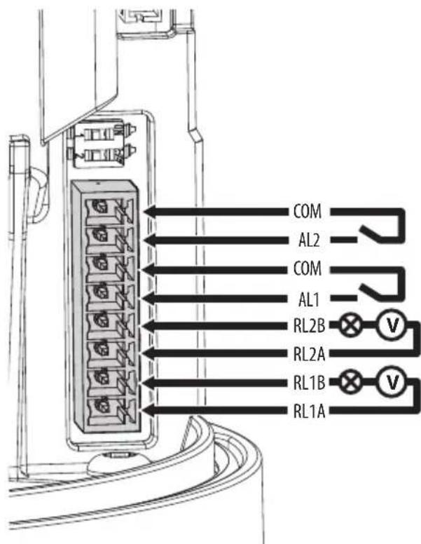
Fig. 23
| CONNECTION OF THE ALARM INPUTS AND RELAYS | |
| Terminals Description | |
| RL1A, RL1B, RL2A, RL2B | Dry contacts of the two relays which can be activated via alarm or by user command |
| AL1, AL2, COM | Self-powered alarm inputs referred to the shared terminal |
Tab. 6
The device can be equipped with a washing system as an accessory. Connect the pump activation signal cable to the indicated relay: RL2A, RL2B.
6.11 Ethernet cable connection

The characteristics of the Ethernet cables can be consulted in the relevant chapter (15 Technical data, page 33).
Use a shielded RJ45 connector on both ends of the cable. The Ethernet cable shield (user side) must always be earthed via the connector.
Connect the ethernet cable to the relative connector (J3, Fig. 24, page 26).
If the product is powered by 90W PoE, the ground cable must be connected to the relevant terminal (GND_EXT, Fig. 24, page 26).
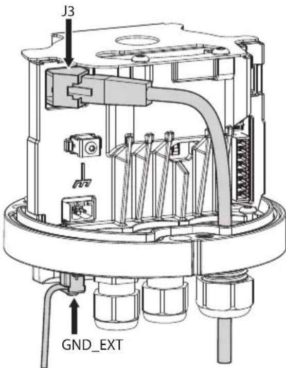
Fig. 24
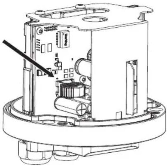
6.12 Installation of the upper body

Installation of the upper body must take place with the base not powered.
Check the LED indicated in the figure is off (Fig. 25, page 27).
natural_image
Technical line drawing of an internal mechanical device with no visible text or symbolsFig. 25
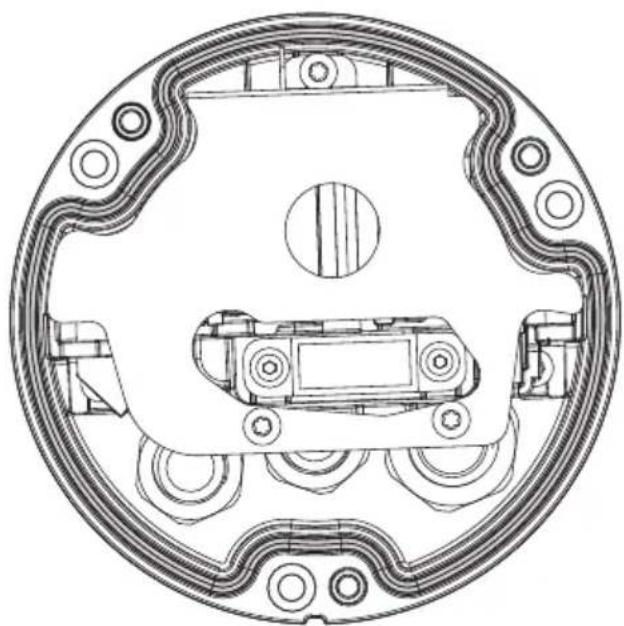
Check the gasket on the base is in good condition and positioned correctly.
natural_image
Technical line drawing of a mechanical component with symmetrical arms and mounting holes (no text or symbols)Fig. 26
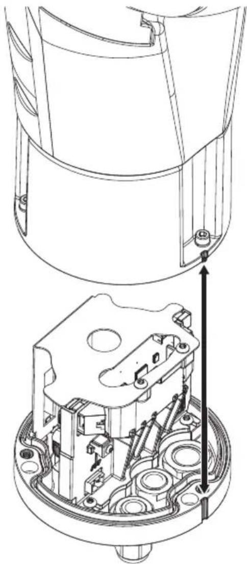
Place the unit body on the base aligning the reference marks. Be especially careful not to damage internal components during installation.
natural_image
Technical line drawing of a mechanical assembly with internal components and a directional arrow (no text or symbols)Fig. 27
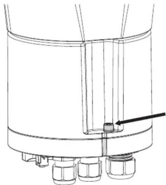
To avoid scratching the product with the hexagonal wrench, align the groove on the body of the product with the screw before screwing it in (Fig. 28, page 28).

natural_image
Technical line drawing of a mechanical component with no visible text or symbolsFig. 28
Fasten the upper unit to the base using the 3 fixing screws.

Pay attention to the fixing. Tightening torque: 4.5Nm (±0.2Nm).

Apply thread-locker into the holes for screws (Loctite 222®).
natural_image
Technical line drawing of a mechanical assembly with no visible text or symbolsFig. 29
7 Switching on

Ensure the unit and the other components of the system are appropriately closed to prevent contact with live parts.

Make sure that all parts are fastened down firmly and safely.

The automatic pre-heating (De-Ice) process could be started whenever the device is switched on and the ambient temperature is below 0^ C (+32°F). The procedure is necessary to guarantee correct operation of the devices even at low temperatures. The duration ranges depending on environmental conditions (from 60 minutes up to 120 minutes).
The unit is switched on by connecting the power supply.
To switch off the unit disconnect the power.
8 Configuration
8.1 Default IP address

The unit is configured to obtain an IP address from a DHCP server.
The IP address acquired via DHCP is visible in the DHCP server log file.
If the DHCP server is not available, the unit automatically configures itself with a self-generated IP address in the 169.254.x.x/16 subnet. Configuring the IP address of the PC as belonging to the same subnet (example: IP address: 169.254.1.1, subnet mask: 255.255.0.0).
Use an ONVIF compliant VMS or a network sniffer to find the IP address of the device (IP scan utility).
8.2 Web interface

Browsers supported (the latest version): Microsoft Edge, Google Chrome, Mozilla Firefox.
8.2.1 First access to the web pages
The first operation in configuring the device consists in connecting to the web interface.
To access the web interface of the product, simply use a browser to connect to address: http://IP address.
On first access, the Home page will be displayed.
To configure the web interface, consult the manual relating to the firmware version installed, available on the product web page of the website www.videotec.com.
9 Accessories and Supports

The complete list of accessories and supports is available on the technical data sheets of the product on the website: www.videotec.com.

For further details on configuration and use, refer to the manual of the relevant accessory or support.
10 Instructions for normal operation

Do not use the wiper if the ambient temperature is under 0^ C or if there is ice.

If it is left on, the wiper automatically disables itself.
The device control can be performed through different modes:
- Through the user's controls of the web interface (8.2 Web interface, page 29).
- Through Video Management Software (VMS) that supports the ONVIF protocol. In this case the special controls are implemented using the auxiliary commands of the ONVIF protocol.
- Through PTZ Assistant software (the PTZ Assistant software is available to download on the product web page of the website: www.videotec.com).
11 Maintenance

Before carrying out any type of maintenance, read the "Safety rules" chapter carefully in the product manual.

CAUTION! Device installation and maintaining must be performed by specialist technical staff only.
When contacting VIDEOTEC for assistance please provide the serial number and the identification code of the model.
Use only VIDEOTEC original spare parts.
11.1 Routine maintenance
11.1.1 Inspecting the cables
The cables should not show signs of damage or wear, which could generate hazardous situations. In cases of damaged or worn cables, repair or replacement will be required.
11.1.2 Replacement of the wiper blade

For further details on configuration and use, refer to the manual of the relevant spare part.
11.2 Extraordinary maintenance
11.2.1 Reset to Factory Default Settings
It is possible to reset to the factory default settings.
The effect of the Factory Default procedure is the same as restoring the factory default settings through the web interface (Hard Reset button).
To execute the default factory procedure, you need to access the DIP switch (S1) on the connectors' card (Fig. 17, page 23).
Follow the procedure below:
- Disconnect the power supply to the unit.
- Open the base of the product (6.2 Opening the base of the product, page 20).
- Set DIP 1 of switch S1 ON.
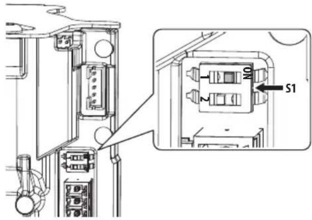
Fig. 30
- Assemble the upper body (6.12 Installation of the upper body, page 27).
• Power the unit. Wait for 2 minutes. - Disconnect the power supply to the unit.
- Open the base of the product (6.2 Opening the base of the product, page 20).
- Reset DIP 1 of switch S1 OFF.
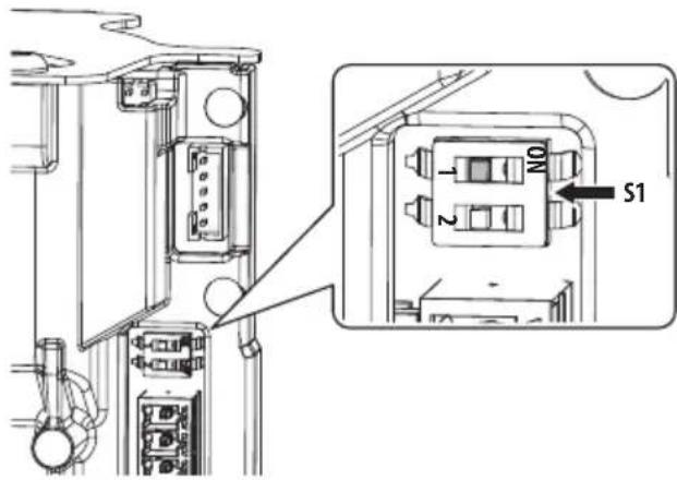
Fig. 31
- Assemble the upper body (6.12 Installation of the upper body, page 27).
- Power the unit.

Once the factory default procedure has finished, you need to configure the unit as described in chapter: 8.1 Default IP address, page 29.
12 Cleaning
12.1 Cleaning the window and external surfaces of the product

Avoid ethyl alcohol, solvents, hydrogenated hydrocarbide, strong acid and alkali. Such products may irreparably damage the surface.
We recommend using a soft cloth with neutral soap diluted with water or specific products to clean the lenses.
12.1.1 Cleaning the germanium window

When cleaning the window, take care not to scratch or damage the outer surface treated with carbon coating. Damage to this coating could also interfere with the transparency of the surface to infrared light.
Cleaning should be done with mild soap diluted with water.
13 Information on disposal and recycling
The European Directive 2012/19/EU on Waste Electrical and Electronic Equipment (WEEE) mandates that these devices should not be disposed of in the normal flow of municipal solid waste, but they should be collected separately in order to optimize the recovery stream and recycling of the materials that they contain and to reduce the impact on human health and the environment due to the presence of potentially hazardous substances.
The symbol of the crossed out bin is marked on all products to remember this.
The waste may be delivered to appropriate collection centers, or may be delivered free of charge to the distributor where you purchased the equipment at the time of purchase of a new equivalent or without obligation to a new purchase for equipment with size smaller than 25cm (9.8in).
For more information on proper disposal of these devices, you can contact the responsible public service.
14 Troubleshooting

Contact an authorised support centre if the problems persist or you have any other issues that are not described here.
PROBLEM The product does not go on.
CAUSE Cabling error.
SOLUTION Make sure the connections are correct.
PROBLEM The product does not go on. The LED indicated in the figure is off (Fig. 25, page 27).
CAUSE Possible fault on fuse F3.
SOLUTION Contact the technical assistance service (VIDEOTEC).
PROBLEM The shooting area do not correspond to the selected preset position.
CAUSE Loss of absolute position reference point.
SOLUTION Reset the equipment by switching off and on again.
PROBLEM With the PoE power supply, the product blocks on the "Maintenance" screen and displays "Error 39".
CAUSE Possible unsuitable PoE injector or DIP switch connector board incorrectly configured.
SOLUTION Follow the instructions in the chapter on the PoE power supply (6.9.2.1 PoH backward compatibility mode enabling, page 25).
15 Technical data

CAUTION! TNV-1 installation type. The installation is type TNV-1, do not connect it to SELV circuits.

CAUTION! In order to reduce the risk of fire, only use UL Listed or CSA certified cables with sections greater than or equal to 0.14mm ^2 (26AWG).
15.1 ULISSE EVO (UE)
15.1.1 General
Easy installation thanks to the self-centering connector
Zero backlash
Quick configuration and setup
Dynamic positioning control system
Functions: Preset, Preset Tour (Patrol), Autoflip, Autopan via Preset Tour
Maximum number of presets: 250
15.1.2 Mechanical
Constructed from aluminium and technopolymer
Epoxy-polyester powder painted, standard colours grey-white (RAL9002) or black (RAL9005)
Horizontal rotation: 360°, continuous rotation
Vertical rotation: from -90^ up to +90^ (with ceiling installation, from -40^ up to +90^ )
Horizontal speed (variable): from 0.1°/s up to 250°/s
Tilt speed (variable): from 0.1°/s up to 250°/s
Accuracy of preset positions: 0.05°
Cable glands: 2xM16 + 1xM20 + special gasket for pre-wired Ethernet cables
Unit weight: 7.1kg (15.6lb) (7.4kg (16.3lb) with LED illuminator)
Glass window
- Thick: 6mm (0.24in)
15.1.3 Electrical
Supply voltage/Current consumption:
• 24Vac ±20%, 5A, 50/60Hz
- 24Vdc ±10%, 5A
- PoE 90W compatible with standard IEEE802.3bt CLASS 8 (LLDP protocol not supported), usable with accessory PSINJ95CH1
- PoH 90W (backward compatibility mode usable with accessory OHEP90INJ, PSINJ95CH1 or OHEP90INJO)
Power consumption:
- 21W, PTZ camera stationary, heating switched off (with the ECO-MODE function enabled, energy saving function that is activated only when the PTZ camera is stationary)
- 27W, PTZ camera stationary, heating switched off (with the ECO-MODE function not enabled)
• 27W, PTZ camera moving, heating switched off - 57W, peak at start-up, heating and de-icing functions switched on
Power consumption with illuminator on:
- 34W, PTZ camera stationary, heating switched off (with the ECO-MODE function enabled, energy saving function that is activated only when the PTZ camera is stationary)
- 40W, PTZ camera stationary, heating switched off (with the ECO-MODE function not enabled)
• 40W, PTZ camera moving, heating switched off - 70W, peak at start-up, heating and de-icing functions switched on
Power supply cables section: from 0.75mm^2 (18AWG) up to 2.5mm^2 (13AWG)
Cables signal section: from 0.14mm^2 (26AWG) up to 1mm^2 (17AWG)
Multipolar cable sheath diameter:
- Cable glands M16: from 4.5mm (0.2in) up to 10mm (0.4in)
- Cable glands M16 with reduction gasket : from 2mm (0.08in) up to 6mm (0.24in)
- Cable glands M20: from 8mm (0.3in) up to 13mm (0.5in)
Alarm inputs: 2 (auto-powered from 12Vdc up to 18Vdc)
Relay outputs: 2 (1A, 30Vac/30Vdc max)
Ethernet cable features
- Minimum cable features: Class D (ISO/IEC11801:1995) or Category 5 (ANSI/EIA/TIA-568-A:1995)
• Shielded twisted cable (STP) - Pair: 4
• DC loop resistance: 25Ohm max - Connector: Shielded RJ45
15.1.4 Network
Ethernet connection: 100 Base-TX
15.1.5 Cybersecurity
Digitally signed firmware
Password restricted access (HTTP digest)
Support of various user access levels
Control of accesses IEEE 802.1X
HTTPS cryptography using TLS1.0, TLS1.1, TLS1.2 and TLS1.3
Centralised certificate management
Complies with ONVIF Security Service specifications
15.1.6 Video
Video encoder
- Communication protocol: ONVIF, Profile Q, Profile S and Profile T
- Device configuration: TCP/IPv4-IPv6, UDP/IPv4-IPv6, HTTP, HTTPS, NTP, DHCP, WS-DISCOVERY, DSCP, IGMP (Multicast), SOAP, DNS
- Streaming: RTSP, RTCP, RTP/IPv4-IPv6, HTTP, Multicast
• Video compression: H.264/AVC, MJPEG, MPEG4, snapshot JPEG
• 3 independent video streams Full HD - Image resolution: from 320x180pixel up to 1920x1080pixel in 8 steps
- Selectable frame rate from 1 to 60 images per second (fps)
- Web Server
- Directional OSD (maximum 4 settable areas)
- Motion Detection
• Video analytics: VIDEOTEC ANALYTICS (optional) - QoS: Differentiated DSCPs for streaming and device management
• SNMP and NTCIP protocols
15.1.7 Video analytics
Ultra-robust detection algorithms and auto-tracking, specifically for outdoor perimeter control.
Targets Classification: People, vehicles, generic objects
Programmable rules for video analysis, VIDEOTEC ANALYTICS (it is possible to rapidly configure up to ten rules for every preset using an intuitive control management interface)
- Line crossing: the target triggers an alarm if it crosses the line in one or both directions
- Entering/leaving area: the target triggers an alarm if it leaves or enters the configured area
- Appearing in area: the target triggers an alarm if it appears inside the configured area
- Loitering: the target triggers an alarm if it stays inside the configured area over the set time
Detection Mask: disables the detection activity in a portion of the image to prevent false alarms
Video Tampering Detection: a specific ONVIF alarm is triggered if the video camera view is obstructed (e.g. spray)
15.1.8 Cameras
Day/Night Full HD 30x DELUX
| Resolution: Full HD 1080p (1920x1080) |
| Image Sensor: 1/2.8" ExmorTM R CMOS sensor |
| Effective Pixels: approx. 2.38 Megapixels |
| Minimum Illumination:Colour: 0.006lx (F1.6, 30 IRE)B/W: 0.0006lx (F1.6, 30 IRE) |
| Focal length: from 4.5mm (wide) up to 135mm (tele) |
| Zoom: 30x (480x with digital zoom) |
| Iris: from F1.6 up to F9.6 (Auto, Manual) |
| Horizontal Viewing Angle: from 61.60° (wide end) up to 2.50° (tele end) |
| Vertical Viewing Angle: from 37.07° (wide end) up to 1.44° (tele end) |
| Shutter speed: from 1/1s up to 1/10000s (Auto, Manual) |
| White balance: Auto, Manual |
| Gain: from 0dB up to 100dB (Auto, Manual) |
| Wide Dynamic Range: 120dB |
| Focus System: Auto, Manual, Trigger |
| Picture Effects: E-flip, Colour enhancement |
| Noise removal: 2D (3 levels), 3D (3 levels) |
| Exposure Control: Auto, Manual, Priority (Iris Priority, Shutter Priority), Brightness, Custom |
| De-fog: On/Off |
| Privacy zones masking: maximum 8 settable masks |
| Indoor Flicker Reduction |
| Auto Slowshutter: Off, On (from 1/30s up to 1/1s) |
| Exposure compensation: Off, On (from level 0 up to level 14) |
| Sharpness: from level 0 up to level 3 |
SONY FCB-EV7520 Day/Night Full HD 30x
| Resolution: Full HD 1080p (1920x1080) |
| Image Sensor: 1/2.8" ExmorTM R CMOS sensor |
| Effective Pixels: approx. 2.13 Megapixels |
| Minimum Illumination:• Colour: 0.0013lx (50 IRE, High sensitivity on)• B/W: 0.0008lx (30 IRE, High sensitivity on) |
| Focal length: from 4.3mm (wide) up to 129mm (tele) |
| Zoom:• 30x• 36x, with Stable Zoom enabled |
| Digital Zoom: 12x |
| Iris: from F1.6 up to F14 (Auto, Manual) |
| Horizontal Viewing Angle: from 63.7° (wide end) up to 2.3° (tele end) |
| Vertical Viewing Angle: from 38.5° (wide end) up to 1.3° (tele end) |
| Shutter speed: from 1/1s up to 1/10000s (Auto, Manual) |
| White balance: Auto, Auto Tracing, Indoor, Outdoor, Manual, Outdoor Auto, Sodium Lamp (Fix/Auto/Outdoor Auto) |
| Gain: from 0dB up to 50.0dB (Auto, Manual) |
| Wide Dynamic Range: 120dB |
| Focus System: Auto (PTZ Trigger, Full Auto), Manual |
| Picture Effects: E-flip |
| Noise removal (2D, 3D): Off, On (from level 1 up to level 5) |
| Exposure Control: Auto, Manual, Priority (Shutter priority, Iris priority, Brightness priority) |
| De-fog: Off, Low, Mid, High |
| Dynamic masking of privacy zones: maximum 24 masks settable, maximum 8 simultaneously displayable |
| Indoor Flicker Reduction |
| Gain Limit: from10.7dB up to 50dB |
| High sensitivity: On/Off |
| Backlight Compensation: On/Off |
| Auto Slowshutter: On/Off |
| Exposure compensation: Off, On (from -10.5dB up to +10.5dB) |
| Sharpness: from level 0 up to level 15 |
| High Light Compensation (HLC): Off, Low, Mid, High, Masking Level (Off, On, from level 1 up to level 15) |
| Digital image stabilization: On/Off |
15.1.9 Illuminators
LED illuminator
Wavelength: 850nm, 940nm (only UEIxxx), white light
UEIxxx
- Wide beam: 40^ (horizontal), 16^ (vertical)
- Spot beam: 14^ (horizontal), 14^ (vertical)
UEIxxxP
- Wide beam: 13^ (horizontal), 13^ (vertical)
- Spot beam: 13^ (horizontal), 13^ (vertical)
Wide beam activation: based on the scene brightness, from alarm input or manually
Spot beam activation (can be activated only when the wide beam is active): can be activated on preset, based on the zoom factor or with the wide beam
Automatic and remote switching on
No calibration required for light beam alignment with the camera
The illuminator does not slow down the PTZ camera's rotation speed
Automatic recognition of the type of illuminator installed
15.1.10 Environment
For indoors and outdoors installation
Operating temperature
- Continuous functioning: from -40^ (-40°F) up to +65^ (149°F) (+50°C (122°F) for versions painted black)
- Temperature test complies with NEMA-TS 2-2003 (R2008) par. 2.1.5.1, test profile fig. 2-1 (from -34°C (-29.2°F) to +74°C (165.2°F)) (not valid for versions with integrated video analysis, VIDEOTEC ANALYTICS)
- De-icing function intervention: from -40°C (-40°F) up to -10°C (14°F)
Wind resistance
- PTZ camera static: 230km/h (143mph) max.
- PTZ camera moving, at the maximum speed, with LED illuminator: 230km/h (143mph) max.
Relative humidity: from 5% up to 95%
15.1.11 Certifications
Electrical safety (CE): EN60950-1, IEC60950-1, EN62368-1, IEC62368-1
Electromagnetic compatibility (CE): EN61000-6-4, EN50130-4, EN55032 (Class A)
Outdoor installation (CE): EN60950-22, IEC60950-22
Photobiological safety (CE): EN62471, IEC62471
IP protection degree (EN60529): IP66, IP67, IP68
Vibration test: EN50130-5, EN60068-2-6
Salty fog resistance: EN50130-5, EN60068-2-52
IK protection degree: IK10 (except glass window)
UL certification (UL60950-1, CAN/CSA C22.2 No. 60950-1-07, UL62368-1 CAN/CSA C22.2 No. 62368-1-14): cULus Listed
Electromagnetic compatibility (North America): FCC part 15 (Class A), ICES-003 (Class A)
Level of protection Type (UL50E): 4X, 6P
EAC certification
Restriction of Hazardous Substances (RoHS), Directive 2011/65/EU
Waste Electrical and Electronic Equipment (WEEE), Directive 2012/19/EU
KC certification (UE21A000J, UE21F000J)
15.1.12 Certifications - Railway applications
Compliance to railway application standard: EN50121-4 (the product requires the filter accessory SURGEPR)
15.1.13 Certifications - Marine applications
Lloyd's Register Marine Type Approval certification (the product requires the filter accessory FM1010 if powered in 24Vac or 24Vdc):
- Test Specification Number 1 (ENV1, ENV2, ENV3, ENV5)
Electromagnetic compatibility: EN60945
Salty fog resistance: EN60068-2-52
Tested at 70°C (158°F) for 16 hours in compliance with EN60068-2-2
15.2 ULISSE EVO THERMAL (UET)
15.2.1 General
Easy installation thanks to the self-centering connector
Zero backlash
Quick configuration and setup
Dynamic positioning control system
Functions: Preset, Preset Tour (Patrol), Autoflip, Autopan via Preset Tour
Maximum number of presets: 250
Radiometric analysis:
- on the 4 central pixels, if the thermal camera has radiometric functions
- definition of a specific area, if the thermal camera has advanced radiometric functions
Radiometric alarm activation: if the temperature is over the threshold set, under the threshold set, between two thresholds set or outside the two thresholds set.
Actions on alarm: activation of digital output, preset tour recall, home position recall, preset position recall and http get request.
15.2.2 Mechanical
Constructed from aluminium and technopolymer
Epoxy-polyester powder painted, standard colours grey-white (RAL9002) or black (RAL9005)
Horizontal rotation: 360^ , continuous rotation
Vertical rotation: from -90^ up to +90^ (with ceiling installation, from -40^ up to +90^ )
Horizontal speed (variable): from 0.1°/s up to 250°/s
Tilt speed (variable): from 0.1°/s up to 250°/s
Accuracy of preset positions: 0.05°
Cable glands: 2xM16 + 1xM20 + special gasket for pre-wired Ethernet cables
Unit weight: 7.1kg (15.6lb)
15.2.3 Housing's window
Germanium window
- Thick: 1.5mm (0.06in)
- External treatment: antiscratch (Hard Carbon Coating - DLC)
- Internal treatment: antireflection
• Spectral range: from 7.5μm up to 14μm
• Medium transmittance (from 7.5μm up to 11.5μm): 91.2%
• Medium transmittance (from 11.5μm up to 14μm): 80.9%
15.2.4 Electrical
Supply voltage/Current consumption:
• 24Vac ±20%, 5A, 50/60Hz
- 24Vdc ±10%, 5A
- PoE 90W compatible with standard IEEE802.3bt CLASS 8 (LLDP protocol not supported), usable with accessory PSINJ95CH1
- PoH 90W (backward compatibility mode usable with accessory OHEP90INJ, PSINJ95CH1 or OHEP90INJO)
Power consumption:
- 21W, PTZ camera stationary, heating switched off (with the ECO-MODE function enabled, energy saving function that is activated only when the PTZ camera is stationary)
- 27W, PTZ camera stationary, heating switched off (with the ECO-MODE function not enabled)
• 27W, PTZ camera moving, heating switched off - 57W, peak at start-up, heating and de-icing functions switched on
Power supply cables section: from 0.75mm^2 (18AWG) up to 2.5mm^2 (13AWG)
Cables signal section: from 0.14mm^2 (26AWG) up to 1mm^2 (17AWG)
Multipolar cable sheath diameter:
- Cable glands M16: from 4.5mm (0.2in) up to 10mm (0.4in)
- Cable glands M16 with reduction gasket : from 2mm (0.08in) up to 6mm (0.24in)
- Cable glands M20: from 8mm (0.3in) up to 13mm (0.5in)
Alarm inputs: 2 (auto-powered from 12Vdc up to 18Vdc)
Relay outputs: 2 (1A, 30Vac/30Vdc max)
Ethernet cable features
- Minimum cable features: Class D (ISO/IEC11801:1995) or Category 5 (ANSI/EIA/TIA-568-A:1995)
• Shielded twisted cable (STP) - Pair: 4
• DC loop resistance: 25Ohm max - Connector: Shielded RJ45
15.2.5 Network
Ethernet connection: 100 Base-TX
15.2.6 Cybersecurity
Digitally signed firmware
Password restricted access (HTTP digest)
Support of various user access levels
Control of accesses IEEE 802.1X
HTTPS cryptography using TLS1.0, TLS1.1, TLS1.2 and TLS1.3
Centralised certificate management
Complies with ONVIF Security Service specifications
15.2.7 Video
Video encoder
- Communication protocol: ONVIF, Profile Q, Profile S and Profile T, ONVIF Thermal Service
- Device configuration: TCP/IPv4-IPv6, UDP/IPv4-IPv6, HTTP, HTTPS, NTP, DHCP, WSDISCOVERY, DSCP, IGMP (Multicast), SOAP, DNS
- Streaming: RTSP, RTCP, RTP/IPv4-IPv6, HTTP, Multicast
• Video compression: H.264/AVC, MJPEG, MPEG4, snapshot JPEG
• 3 independent video streams - Image resolution: from 160x120pixel up to 720x480pixel in 5 steps
- Selectable frame rate from 1 to 30 images per second (fps)
- Web Server
- Directional OSD (maximum 4 settable areas)
- Motion Detection
- QoS: Differentiated DSCPs for streaming and device management
• SNMP and NTCIP protocols
15.2.8 Cameras
| THERMAL CAMERAS (RESOLUTION 336X256) | |||||
| Lens | 9mm | 13mm | 19mm | 25mm | 35mm |
| VOx microbolometer sensor not cooled | √ √ √ √ √ | ||||
| Interpolated resolution 720x480 720x480 720x480 720x480 720x480 720x480 720x480 720x480 720x480 720x480 720x480 720x480 720x480 72 | 720x480 720x480 | ||||
| Pixel dimensions 17μm 17μm 17μm 17μm 17μm | |||||
| Spectral response - long wave infrared (LWIR) from 7.5μm to 13.5μm | from 7.5μm to 13.5μm | from 7.5μm to 13.5μm | from 7.5μm to 13.5μm | from 7.5μm to 13.5μm | from 7.5μm to 13.5μm |
| Internal shutter (only for sensor compensation) | Video stop <1s | Video stop <1s | Video stop <1s | Video stop <1s | Video stop <1s |
| Digital Detail Enhancement (DDE) | √ √ √ √ √ | ||||
| Digital Zoom | 2x, 4x | 2x, 4x | 2x, 4x | 2x, 4x | 2x, 4x |
| Image updating frequency | 7.5fps | 7.5fps | 7.5fps | 7.5fps | 7.5fps |
| Image updating high frequency | 30fps | 30fps | 30fps | 30fps | 30fps |
| Scene range (High Gain) | -40°C ÷ +160°C (-40°F ÷ +320°F) | -40°C ÷ +160°C (-40°F ÷ +320°F) | -40°C ÷ +160°C (-40°F ÷ +320°F) | -40°C ÷ +160°C (-40°F ÷ +320°F) | -40°C ÷ +160°C (-40°F ÷ +320°F) |
| Scene range (Low Gain) | -40°C ÷ +550°C (-40°F ÷ +1022°F) | -40°C ÷ +550°C (-40°F ÷ +1022°F) | -40°C ÷ +550°C (-40°F ÷ +1022°F) | -40°C ÷ +550°C (-40°F ÷ +1022°F) | -40°C ÷ +550°C (-40°F ÷ +1022°F) |
| Horizontal field of view (HFOV) | 35° | 25° | 17° | 13° | 9.3° |
| Vertical field of view (VFOV) | 27° | 19° | 13° | 10° | 7.1° |
| f-number | f/1.25 | f/1.25 | f/1.25 | f/1.1 | f/1.2 |
| Thermal sensitivity (NETD), thermal camera with radiometric functions | <50mK at f/1.0 | <50mK at f/1.0 | <50mK at f/1.0 | <50mK at f/1.0 | <50mK at f/1.0 |
| Thermal sensitivity (NETD), thermal camera with advanced radiometric functions | <30mK at f/1.0 | <30mK at f/1.0 | <30mK at f/1.0 | <30mK at f/1.0 | <30mK at f/1.0 |
| Person (detection / recognition / identification) | 285m / 71m / 36m (935ft / 233ft / 118ft) | 440m / 112m / 56m (1443ft / 2368ft / 183ft) | 640m / 160m / 80m (2099ft / 524ft / 262ft) | 930m / 230m / 116m (3051ft / 754ft / 380ft) | 1280m / 320m / 160m (4199ft / 1050ft / 525ft) |
| Car (detection / recognition / identification) | 880m / 220m / 108m (2887ft / 722ft / 354ft) | 1340m / 340m / 170m (4396ft / 1115ft / 557ft) | 1950m / 500m / 250m (6397ft/ 1640ft/ 820ft) | 2800m / 710m / 360m (9186ft / 2329ft / 1181ft) | 3850m / 950m / 295m (12631ft / 3116ft / 967ft) |
Tab. 7 Radiometric analysis does not affect camera performance.
THERMAL CAMERAS (RESOLUTION 640X512)
| Lens | 9mm | 13mm | 19mm | 25mm | 35mm |
| VOx microbolometer sensor not cooled | √ √ √ √ √ | ||||
| Interpolated resolution 720x480 720x480 720x480 720x480 720x480 720x480 720x480 720x480 720x480 720x480 720x480 720x480 720x480 72 | 720x480 720x480 | ||||
| Pixel dimensions 17μm 17μm 17μm 17μm 17μm | |||||
| Spectral response - long wave infrared (LWIR) from 7.5μm to 13.5μm | from 7.5μm to 13.5μm | from 7.5μm to 13.5μm | from 7.5μm to 13.5μm | from 7.5μm to 13.5μm | from 7.5μm to 13.5μm |
| Internal shutter (only for sensor compensation) | Video stop <1s | Video stop <1s | Video stop <1s | Video stop <1s | Video stop <1s |
| Digital Detail Enhancement (DDE) | √ √ √ √ √ | ||||
| Digital Zoom | 2x, 4x, 8x | 2x, 4x, 8x | 2x, 4x, 8x | 2x, 4x, 8x | 2x, 4x, 8x |
| Image updating frequency | 7.5fps | 7.5fps | 7.5fps | 7.5fps | 7.5fps |
| Image updating high frequency | 30fps | 30fps | 30fps | 30fps | 30fps |
| Scene range (High Gain) | -40°C ÷ +160°C(-40°F ÷+320°F) | -40°C ÷ +160°C(-40°F ÷+320°F) | -40°C ÷ +160°C(-40°F ÷+320°F) | -40°C ÷ +160°C(-40°F ÷+320°F) | -40°C ÷ +160°C(-40°F ÷+320°F) |
| Scene range (Low Gain) | -40°C ÷ +550°C(-40°F ÷+1022°F) | -40°C ÷ +550°C(-40°F ÷+1022°F) | -40°C ÷ +550°C(-40°F ÷+1022°F) | -40°C ÷ +550°C(-40°F ÷+1022°F) | -40°C ÷ +550°C(-40°F ÷+1022°F) |
| Horizontal field of view (HFOV) | 69° | 45° | 32° | 25° | 18° |
| Vertical field of view (VFOV) | 56° | 37° | 26° | 20° | 14° |
| f-number | f/1.4 | f/1.25 | f/1.25 | f/1.1 | f/1.2 |
| Thermal sensitivity (NETD), thermal camera with radiometric functions | <50mK at f/1.0 | <50mK at f/1.0 | <50mK at f/1.0 | <50mK at f/1.0 | <50mK at f/1.0 |
| Thermal sensitivity (NETD), thermal camera with advanced radiometric functions | <30mK at f/1.0 | <30mK at f/1.0 | <30mK at f/1.0 | <30mK at f/1.0 | <30mK at f/1.0 |
| Person (detection / recognition / identification) 250m / 63m /31m (820ft /207ft / 102ft) | 390m / 95m /47m (1280ft /312ft / 154ft) | 570m / 144m/ 72m (1870 /472 / 236ft) | 820m / 210m /104m (2690ft /689ft / 341ft) | 1140m / 280m/ 142m (3740ft/ 919ft / 466ft) | |
| Car (detection / recognition / identification) | 720m / 175m/88m (2362 /574 / 289ft) | 1080m / 275m/ 140m (3543ft/ 902ft / 459ft) | 1550m / 400m/ 200m (5085ft/ 1312ft / 656ft) | 2200m / 580m/ 290m (7218ft/ 1903ft /951ft) | 3000m / 800m/ 200m (9843ft/ 2625ft /656ft) |
Tab. 8 Radiometric analysis does not affect camera performance.
15.2.9 Environment
For indoors and outdoors installation
Operating temperature
- Continuous functioning: from -40°C (-40°F) up to +65°C (149°F) (+50°C (122°F) for versions painted black)
- Temperature test complies with NEMA-TS 2-2003 (R2008) par. 2.1.5.1, test profile fig. 2-1 (from -34°C (-29.2°F) to +74°C (165.2°F))
- De-icing function intervention: from -40^ (-40°F) up to -10^ (14°F)
Wind resistance
• PTZ camera static: 230km/h (143mph) max.
- PTZ camera moving, at the maximum speed: 230km/h (143mph) max.
Relative humidity: from 5% up to 95%
15.2.10 Certifications
Electrical safety (CE): EN60950-1, IEC60950-1, EN62368-1, IEC62368-1
Electromagnetic compatibility (CE): EN61000-6-4, EN50130-4, EN55032 (Class A)
Outdoor installation (CE): EN60950-22, IEC60950-22
IP protection degree (EN60529): IP66, IP67, IP68
Vibration test: EN50130-5, EN60068-2-6
Salty fog resistance: EN50130-5, EN60068-2-52
IK protection degree: IK10 (except germanium window)
UL certification (UL60950-1, CAN/CSA C22.2 No. 60950-1-07, UL62368-1 CAN/CSA C22.2 No. 62368-1-14): cULus Listed
Electromagnetic compatibility (North America): FCC part 15 (Class A), ICES-003 (Class A)
Level of protection Type (UL50E): 4X, 6P
EAC certification
Restriction of Hazardous Substances (RoHS), Directive 2011/65/EU
Waste Electrical and Electronic Equipment (WEEE), Directive 2012/19/EU
15.2.11 Certifications - Railway applications
Compliance to railway application standard: EN50121-4 (the product requires the filter accessory SURGEPR)
15.2.12 Certifications - Marine applications
Lloyd's Register Marine Type Approval certification (the product requires the filter accessory FM1010 if powered in 24Vac or 24Vdc):
- Test Specification Number 1 (ENV1, ENV2, ENV3, ENV5)
Electromagnetic compatibility: EN60945
Salty fog resistance: EN60068-2-52
Tested at 70°C (158°F) for 16 hours in compliance with EN60068-2-2
15.3 ULISSE EVO DUAL (UED)
15.3.1 General
Easy installation thanks to the self-centering connector
Zero backlash
Quick configuration and setup
Dynamic positioning control system
Functions: Preset, Preset Tour (Patrol), Autoflip, Autopan via Preset Tour
Maximum number of presets: 250
15.3.2 Mechanical
Constructed from aluminium and technopolymer
Epoxy-polyester powder painted, standard colour grey-white (RAL9002)
Horizontal rotation: 360°, continuous rotation
Vertical rotation: from -90^ up to +90^ (with ceiling installation, from -40^ up to +90^ )
Horizontal speed (variable): from 0.1°/s up to 250°/s
Tilt speed (variable): from 0.1°/s up to 250°/s
Accuracy of preset positions: 0.05°
Cable glands: 2xM16 + 1xM20 + special gasket for pre-wired Ethernet cables
Unit weight: 7.4kg (16.3lb)
15.3.3 Housing's window
Window with extra clear tempered glass
- Thick: 6mm (0.24in)
Germanium window
- Thick: 1.5mm (0.06in)
- Scratch-resistant treatment (Hard Carbon Coating - DLC)
- Antireflection treatment
• Spectral range: from 7.5μm up to 14μm
• Medium transmittance (from 7.5μm up to 11.5μm): 91.2%
• Medium transmittance (from 11.5μm up to 14μm): 80.9%
15.3.4 Electrical
Supply voltage/Current consumption:
• 24Vac ±20%, 5A, 50/60Hz
- 24Vdc ±10%, 5A
- PoE 90W compatible with standard IEEE802.3bt CLASS 8 (LLDP protocol not supported), usable with accessory PSINJ95CH1
- PoH 90W (backward compatibility mode usable with accessory OHEP90INJ, PSINJ95CH1 or OHEP90INJO)
Power consumption:
- 23W, PTZ camera stationary, heating switched off (with the ECO-MODE function enabled, energy saving function that is activated only when the PTZ camera is stationary)
- 29W, PTZ camera stationary, heating switched off (with the ECO-MODE function not enabled)
• 29W, PTZ camera moving, heating switched off
- 59W, peak at start-up, heating and de-icing functions switched on
Power supply cables section: from 0.75mm^2 (18AWG) up to 2.5mm^2 (13AWG)
Cables signal section: from 0.14mm^2 (26AWG) up to 1mm^2 (17AWG)
Multipolar cable sheath diameter:
- Cable glands M16: from 4.5mm (0.2in) up to 10mm (0.4in)
- Cable glands M16 with reduction gasket: from 2mm (0.08in) up to 6mm (0.24in)
- Cable glands M20: from 8mm (0.3in) up to 13mm (0.5in)
Alarm inputs: 2 (auto-powered from 12Vdc up to 18Vdc)
Relay outputs: 2 (1A, 30Vac/30Vdc max)
Ethernet cable features
- Minimum cable features: Class D (ISO/IEC11801:1995) or Category 5 (ANSI/EIA/TIA-568-A:1995)
• Shielded twisted cable (STP)
- Pair: 4
• DC loop resistance: 25Ohm max
- Connector: Shielded RJ45
15.3.5 Network
Ethernet connection: 100 Base-TX
15.3.6 Cybersecurity
Digitally signed firmware
Password restricted access (HTTP digest)
Support of various user access levels
Control of accesses IEEE 802.1X
HTTPS cryptography using TLS1.0, TLS1.1, TLS1.2 and TLS1.3
Centralised certificate management
Complies with ONVIF Security Service specifications
15.3.7 Video
Day/Night camera
Video encoder
- Communication protocol: ONVIF, Profile Q, Profile S and Profile T
- Device configuration: TCP/IPv4-IPv6, UDP/IPv4-IPv6, HTTP, HTTPS, NTP, DHCP, WS-DISCOVERY, DSCP, IGMP (Multicast), SOAP, DNS
- Streaming: RTSP, RTCP, RTP/IPv4-IPv6, HTTP, Multicast
• Video compression: H.264/AVC, MJPEG, MPEG4, snapshot JPEG
• 3 independent video streams Full HD
• Image resolution: from 320x180pixel up to 1920x1080pixel in 8 steps - Selectable frame rate from 1 to 60 images per second (fps)
- Web Server
- Directional OSD (maximum 4 settable areas)
- Motion Detection
- QoS: Differentiated DSCPs for streaming and device management
• SNMP and NTCIP protocols
Thermal Camera
Video encoder
- Communication protocol: ONVIF, Profile Q, Profile S and Profile T, ONVIF Thermal Service
- Device configuration: TCP/IPv4-IPv6, UDP/IPv4-IPv6, HTTP, HTTPS, NTP, DHCP, WSDISCOVERY, DSCP, IGMP (Multicast), SOAP, DNS
- Streaming: RTSP, RTCP, RTP/IPv4-IPv6, HTTP, Multicast
• Video compression: H.264/AVC, MJPEG, MPEG4, snapshot JPEG
• 3 independent video streams - Image resolution: from 160x120pixel up to 720x480pixel in 5 steps
- Selectable frame rate from 1 to 30 images per second (fps)
- Web Server
- Directional OSD (maximum 4 settable areas)
- Motion Detection
- QoS: Differentiated DSCPs for streaming and device management
• SNMP and NTCIP protocols
15.3.8 Day/Night cameras
SONY FCB-EV7520 Day/Night Full HD 30x
Resolution: Full HD 1080p (1920x1080)
Image Sensor: 1/2.8" Exmor™ R CMOS sensor
Effective Pixels: approx. 2.13 Megapixels
Minimum Illumination:
• Colour: 0.0013lx (50 IRE, High sensitivity on)
• B/W: 0.0008lx (30 IRE, High sensitivity on)
Focal length: from 4.3mm (wide) up to 129mm (tele)
Zoom:
- 30x
- 36x, with Stable Zoom enabled
Digital Zoom: 12x
Iris: from F1.6 up to F14 (Auto, Manual)
Horizontal Viewing Angle: from 63.7° (wide end) up to 2.3° (tele end)
Vertical Viewing Angle: from 38.5^ (wide end) up to 1.3^ (tele end)
Shutter speed: from 1/1s up to 1/10000s (Auto, Manual)
White balance: Auto, Auto Tracing, Indoor, Outdoor, Manual, Outdoor Auto, Sodium Lamp (Fix/Auto/Outdoor Auto)
Gain: from 0dB up to 50.0dB (Auto, Manual)
Wide Dynamic Range: 120dB
Focus System: Auto (PTZ Trigger, Full Auto), Manual
Picture Effects: E-flip
Noise removal (2D, 3D): Off, On (from level 1 up to level 5)
Exposure Control: Auto, Manual, Priority (Shutter priority, Iris priority, Brightness priority)
De-fog: Off, Low, Mid, High
Dynamic masking of privacy zones: maximum 24 masks settable, maximum 8 simultaneously displayable
Indoor Flicker Reduction
Gain Limit: from 10.7dB up to 50dB
High sensitivity: On/Off
Backlight Compensation: On/Off
Auto Slowshutter: On/Off
Exposure compensation: Off, On (from -10.5dB up to +10.5dB)
Sharpness: from level 0 up to level 15
High Light Compensation (HLC): Off, Low, Mid, High, Masking Level (Off, On, from level 1 up to level 15)
Digital image stabilization: On/Off
15.3.9 Thermal Cameras
| THERMAL CAMERAS (RESOLUTION 320X256) | |||
| Lens 6.3mm 9.1mm 18mm | |||
| VOx microbolometer sensor not cooled | √ √ √ | ||
| Interpolated resolution 720x480 720x480 720x480 | |||
| Pixel dimensions 12μm 12μm 12μm | |||
| Spectral response - long wave infrared (LWIR) from 7.5μm up to 14μm from 7.5μm up to 14μm from 7.5μm up to 14μm | |||
| Internal shutter (only for sensor compensation) | Video stop < 1s | Video stop < 1s | Video stop < 1s |
| Digital Detail Enhancement (DDE) | √ √ √ | ||
| Adaptive Contrast Enhancement (ACE) | √ √ √ | ||
| Digital Zoom | 8x | 8x | 8x |
| Image updating frequency | 7.5fps | 7.5fps | 7.5fps |
| Image updating high frequency | 30fps | 30fps | 30fps |
| Typical dynamic range scene 320 | from -40°C (-40°F) up to +160°C (320°F) or from -40°C (-40°F) up to +370°C (698°F) (selectable) | from -40°C (-40°F) up to +160°C (320°F) or from -40°C (-40°F) up to +370°C (698°F) (selectable) | from -40°C (-40°F) up to +160°C (320°F) or from -40°C (-40°F) up to +370°C (698°F)(selectable) |
| Horizontal field of view | 34° | 24.1° | 12° |
| Vertical field of view | 27.2° | 19.2° | 9.6° |
| F-number | F/1.01 | F/1.02 | F/1.04 |
| Thermal sensitivity (NETD) | < 50mK at f/1.0 | < 50mK at f/1.0 | < 50mK at f/1.0 |
| Person (detection / recognition / identification) | 131/33/20 | 188/47/29 | 381/95/59 |
| Car (detection / recognition / identification) | 608/152/94 | 870/218/134 | 1753/438/270 |
Tab. 9
| THERMAL CAMERAS (RESOLUTION 640X512) | |||
| Lens | 8.7mm | 14mm | 24.4mm |
| VOx microbolometer sensor not cooled | √ √ √ | ||
| Interpolated resolution 720x480 720x480 720x480 | |||
| Pixel dimensions 12μm 12μm 12μm | |||
| Spectral response - long wave infrared (LWIR) from 7.5μm | up to 14μm from 7.5μm up to 14μm from 7.5μm up to 14μm | ||
| Digital Detail Enhancement (DDE) | √ √ √ | ||
| Adaptive Contrast Enhancement (ACE) | √ √ √ | ||
| Digital Zoom | 8x | 8x | 8x |
| Image updating frequency | 7.5fps | 7.5fps | 7.5fps |
| Image updating high frequency | 30fps | 30fps | 30fps |
| Typical dynamic range scene 640 | from -40°C (-40°F)up to +150°C (302°F)or from -40°C (-40°F)up to +500°C (932°F)(selectable) | from -40°C (-40°F)up to +150°C (302°F)or from -40°C (-40°F)up to +500°C (932°F)(selectable) | from -40°C (-40°F)up to +150°C (302°F)or from -40°C (-40°F)up to +500°C (932°F)( selectable) |
| Horizontal field of view | 50° | 32° | 18° |
| Vertical field of view | 37.5° | 25.6° | 13.5° |
| F-number | F/1.01 | F/1.00 | F/1.00 |
| Thermal sensitivity (NETD) | < 50mK at f/1.0 | < 50mK at f/1.0 | < 50mK at f/1.0 |
| Person (detection / recognition / identification) | 172/43/26 | 279/70/43 | 505/126/78 |
| Car (detection / recognition / identification) | 867/217/133 | 1296/324/199 | 2506/627/386 |
Tab. 10
15.3.10 Environment
For indoors and outdoors installation
Operating temperature
- Continuous functioning: from -40^ (-40°F) up to +60^ (140°F) (+65°C (149°F) for versions with 320x256 sensor)
- Temperature test complies with NEMA-TS 2-2003 (R2008) par. 2.1.5.1, test profile fig. 2-1 (from -34°C (-29.2°F) to +74°C (165.2°F)) (only for versions with 320x256 sensor)
- De-icing function intervention: from -40^ (-40°F) up to -10^ (14°F)
Wind resistance
- PTZ camera static: 230km/h (143mph) max.
- PTZ camera moving, at the maximum speed: 230km/h (143mph) max.
Relative humidity: from 5% up to 95%
15.3.11 Certifications
Electrical safety (CE): EN60950-1, IEC60950-1, EN62368-1, IEC62368-1
Electromagnetic compatibility (CE): EN61000-6-4, EN50130-4, EN55032 (Class A)
Outdoor installation (CE): EN60950-22, IEC60950-22
IP protection degree (EN60529): IP66, IP67, IP68
Vibration test: EN50130-5, EN60068-2-6
Salty fog resistance: EN50130-5, EN60068-2-52
IK protection degree: IK10 (except glass window and germanium window)
UL certification (UL60950-1, CAN/CSA C22.2 No. 60950-1-07, UL62368-1 CAN/CSA C22.2 No. 62368-1-14): cULus Listed
Electromagnetic compatibility (North America): FCC part 15 (Class A), ICES-003 (Class A)
Level of protection Type (UL50E): 4X, 6P
EAC certification
Restriction of Hazardous Substances (RoHS), Directive 2011/65/EU
Waste Electrical and Electronic Equipment (WEEE), Directive 2012/19/EU
15.3.12 Certifications - Railway applications
Compliance to railway application standard: EN50121-4 (the product requires the filter accessory SURGEPR)
16 Technical drawings

The indicated measurements are expressed in millimetres.
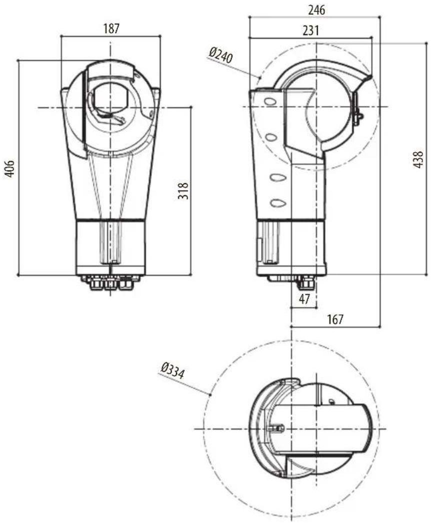
Fig. 32 ULISSE EVO.
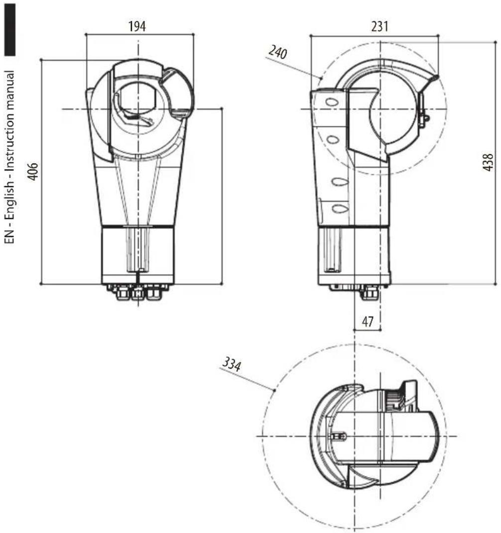
Fig. 33 ULISSE EVO with LED illuminator.

Fig. 34 ULISSE EVO THERMAL.
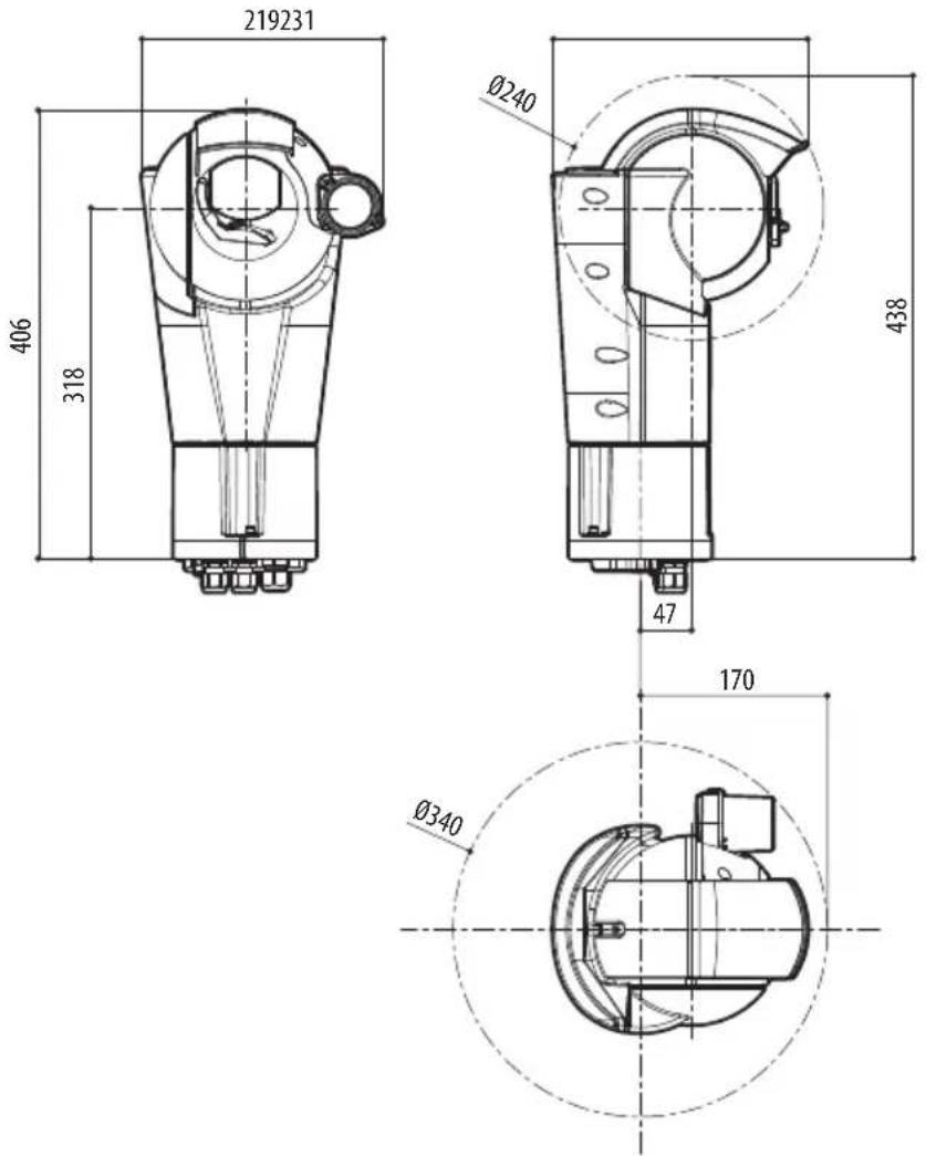
Fig. 35 ULISSE EVO DUAL.
ULISSE EVO (UE)
ULISSE EVO THERMAL (UET)
ULISSE EVO DUAL (UED)
natural_image
Technical line drawings of three mechanical components with mounting holes and internal cavities (no text or symbols)Sommario
15.2.6 Cybersecurity....38
15.2.7 Video....38
15.2.8 Telecamere 39
15.2.9 Ambiente 41
15.3.6 Cybersecurity....43
Fig. 1
natural_image
Technical line drawing of a mechanical component with bolt holes and a highlighted section (no text or symbols)Fig. 2
Fig. 4
natural_image
Technical line drawing of a mechanical component with no visible text or symbolsFig. 10
natural_image
Technical line drawing of a cylindrical mechanical component with bolted base and mounting flanges (no text or symbols)Fig. 11
natural_image
Mechanical assembly diagram showing a shaft and housing with directional arrows indicating motion (no text or symbols)Fig. 12
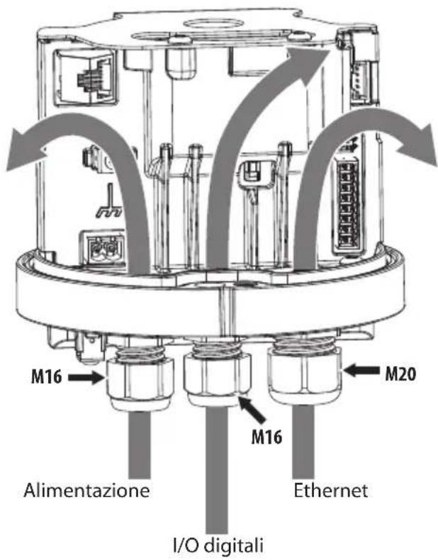
Fig. 13
natural_image
Technical line drawing of a mechanical component with no visible text or symbolsnatural_image
Technical line drawing of a mechanical component with no visible text or symbolsnatural_image
Technical line drawing of a mechanical component with a pulley and mounting bracket (no text or symbols)Fig. 16
natural_image
Technical drawing of a mechanical connector or bracket (no text or symbols)Fig. 20
natural_image
Technical diagram of a mechanical assembly with internal components and labeled part J6 (no readable text or symbols beyond label)Fig. 21
natural_image
Technical illustration of a multi-pin electrical connector with multiple slots and mounting holes (no text or symbols)Fig. 22
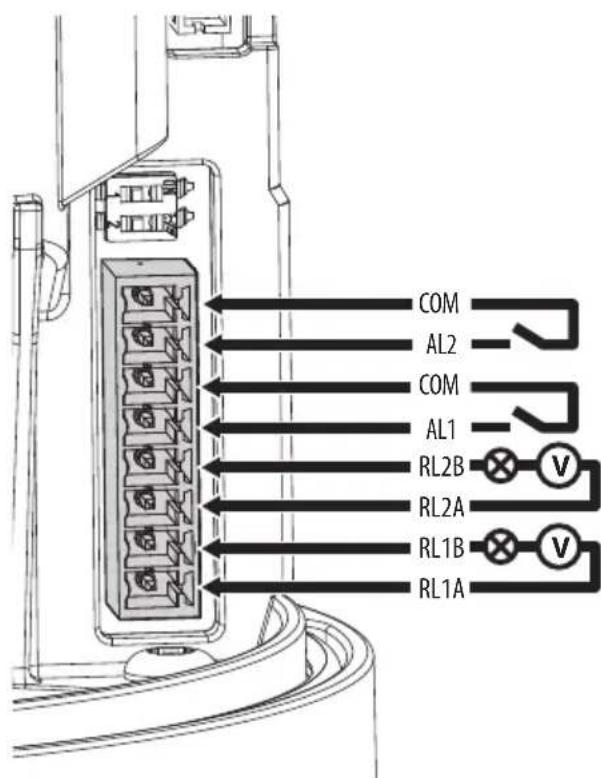
Fig. 23
natural_image
Technical line drawing of an internal mechanical assembly with no visible text or symbolsFig. 25
natural_image
Technical line drawing of a circular mechanical component with internal components and mounting holes (no text or symbols)Fig. 26
natural_image
Technical line drawing of a mechanical assembly with internal components and a directional arrow (no text or symbols)Fig. 27
natural_image
Technical line drawing of a mechanical component with no visible text or symbolsFig. 28
natural_image
Technical line drawing of a mechanical component with no visible text or symbolsFig. 29
7 Accensione

Fig. 30
Fig. 31
15.1.5 Cybersecurity
Firmware firmato digitalmente
15.2.6 Cybersecurity
Firmware firmato digitalmente
15.3.6 Cybersecurity
Firmware firmato digitalmente
Telecamera Day/Night
Encoder video
15.3.8 Telecamere Day/Night
SONY FCB-EV7520 Day/Night Full HD 30x
Indoor Flicker Reduction
High sensitivity: On/Off
Auto Slowshutter: On/Off
natural_image
Technical line drawings of three mechanical components with mounting holes and internal cavities (no text or symbols)Sommaire
6 Installation....14
15.1.11 Certifications ....36
15.1.12 Certifications - Applications ferroviaires ....36
15.1.13 Certifications - Applications marines....36
15.2 ULISSE EVO THERMAL (UET)....37
15.2.6 Cybersecurity....38
15.2.7 Vidéo....38
15.2.8 Caméras....39
15.2.10 Certifications....41
15.2.11 Certifications - Applications ferroviaires....41
15.2.12 Certifications - Applications marines 41
15.3 ULISSE EVO DUAL (UED) 42
15.3.6 Cybersecurity....43
- Double toit.
- Corps.
- Base.
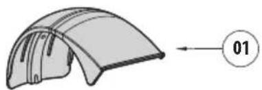
natural_image
Diagram of a curved, segmented structure with directional arrow and circled number 01 (no text or symbols on the diagram itself)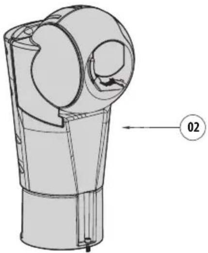
natural_image
Technical line drawing of a mechanical component with no visible text or symbols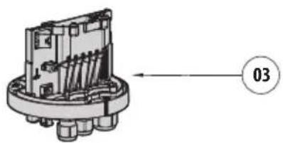
natural_image
Mechanical component diagram showing internal spring assembly with no visible text or symbolsFig. 1
natural_image
Technical line drawing of a mechanical component with bolt holes and a highlighted section (no text or symbols)Fig. 2
Fig. 4
natural_image
Technical line drawing of a mechanical component with no visible text or symbolsFig. 10
natural_image
Technical line drawing of a cylindrical mechanical component with a small inset showing a small component, no text or symbols present.Fig. 11
6.3 Fixation du support

natural_image
Mechanical assembly diagram showing a shaft and housing with directional arrows indicating motion (no text or symbols)Fig. 12
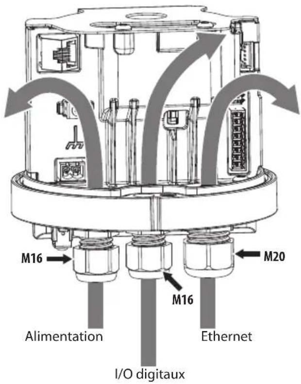
Fig. 13
natural_image
Technical line drawing of a mechanical component with no visible text or symbolsnatural_image
Technical line drawing of a mechanical component with no visible text or symbolsnatural_image
Technical line drawing of a mechanical component with a bracket and mounting holes (no text or symbols)Fig. 16
natural_image
Technical drawing of a mechanical connector or bracket (no text or symbols)Fig. 20
6.9.2 Alimentation en PoE 90W
natural_image
Technical diagram of a mechanical assembly with internal components and labeled part J6 (no readable text or symbols beyond label)Fig. 21
natural_image
3D technical illustration of a multi-pin electrical connector with multiple slots and terminal blocks (no text or symbols)Fig. 22
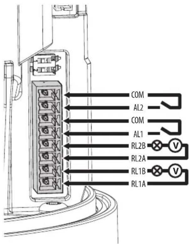
Fig. 23
natural_image
Technical line drawing of an internal mechanical device with no visible text or symbolsFig. 25
natural_image
Technical line drawing of a mechanical component with circular and radial features (no text or symbols)Fig. 26
natural_image
Technical line drawing of a mechanical assembly with internal components and a directional arrow (no text or symbols)Fig. 27
natural_image
Technical line drawing of a mechanical component with no visible text or symbolsFig. 28
natural_image
Technical line drawing of a mechanical component with no visible text or symbolsFig. 29
7 Allumage

Fig. 30
Fig. 31
15.1.5 Cybersecurity
Indoor Flicker Reduction
Indoor Flicker Reduction
High sensitivity: On/Off
Compensation Backlight: On/Off
Auto Slowshutter: On/Off
Restriction of Hazardous Substances (RoHS), Directive 2011/65/EU
Waste Electrical and Electronic Equipment (WEEE), Directive 2012/19/EU
Certification KC (UE21A000J, UE21F000J)
15.1.12 Certifications - Applications ferroviaires
15.2.6 Cybersecurity
Restriction of Hazardous Substances (RoHS), Directive 2011/65/EU
Waste Electrical and Electronic Equipment (WEEE), Directive 2012/19/EU
15.2.11 Certifications - Applications ferroviaires
15.3.6 Cybersecurity
Indoor Flicker Reduction
High sensitivity: On/Off
Compensation Backlight: On/Off
Auto Slowshutter: On/Off
Restriction of Hazardous Substances (RoHS), Directive 2011/65/EU
Waste Electrical and Electronic Equipment (WEEE), Directive 2012/19/EU
15.3.12 Certifications - Applications ferroviaires
natural_image
Technical line drawings of three mechanical components with mounting holes and internal cavities (no text or symbols)Inhaltsverzeichnis
1 Allgemeines....7
6 Installation....14
6.1 Montageoptionen....14
15.2.6 Cybersecurity....38
15.2.7 Video....38
15.2.8 Kamera....39
15.2.9 Umgebung 41
15.3.6 Cybersecurity....43
Abb. 1
natural_image
Technical line drawing of a mechanical component with mounting holes and a highlighted section (no text or symbols)Abb. 2
Hazardous moving parts. Keep fingers and other body parts away.
AVERTISSEMENT!
Abb. 4
natural_image
Technical line drawing of a mechanical component with no visible text or symbolsAbb. 10
natural_image
Technical line drawing of a cylindrical mechanical component with bolted base and internal structure (no text or symbols)Abb. 11
natural_image
Mechanical assembly diagram showing a shaft and housing with directional arrows indicating motion (no text or symbols)Abb. 12
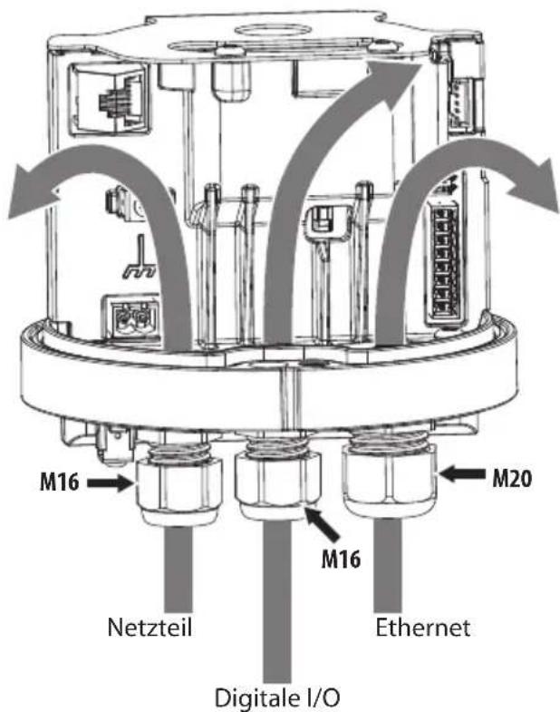
natural_image
Technical line drawing of a mechanical component with no visible text or symbolsnatural_image
Technical line drawing of a mechanical component with no visible text or symbolsnatural_image
Technical line drawing of a mechanical component with a bracket and mounting holes (no text or symbols)Abb. 16
natural_image
Technical drawing of a mechanical component with two slots and a top bracket (no text or symbols)Abb. 20
natural_image
Technical diagram of a mechanical assembly with labeled component J6, showing internal components and connections (no readable text or symbols beyond label)Abb. 21
natural_image
Technical illustration of a multi-pin electrical connector with multiple slots and terminal blocks (no text or symbols)Abb. 22
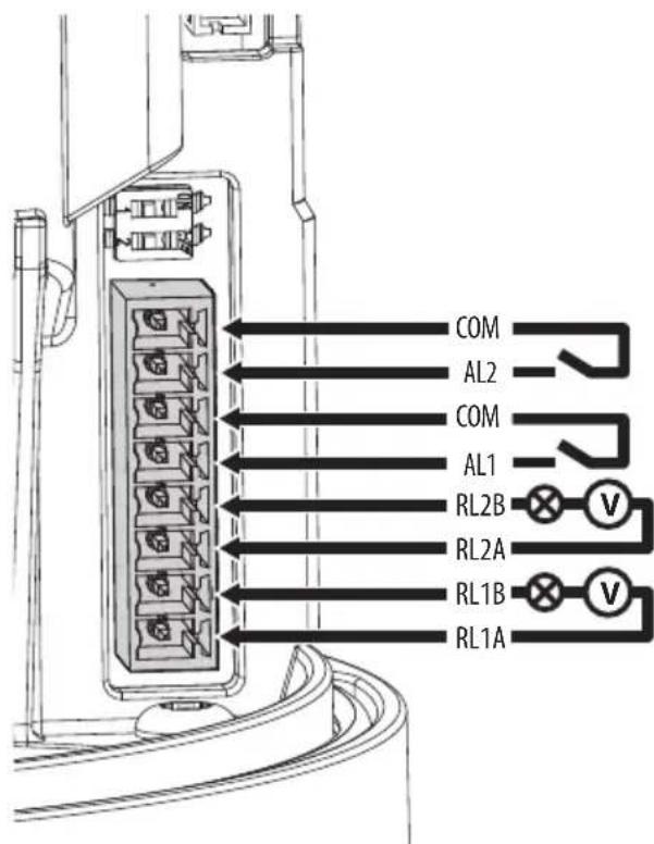
Abb. 23
natural_image
Technical line drawing of an internal mechanical device with no visible text or symbolsAbb. 25
natural_image
Technical line drawing of a mechanical component with circular and radial features (no text or symbols)Abb. 26
natural_image
Technical line drawing of a mechanical assembly with internal components and a directional arrow (no text or symbols)Abb. 27
natural_image
Technical line drawing of a mechanical component with no visible text or symbolsAbb. 28
natural_image
Technical line drawing of a cylindrical mechanical component with a small inset showing a small component, no text or symbols present.Abb. 29
7 Einschaltung

Abb. 30
Abb. 31
15.1.5 Cybersecurity
Indoor Flicker Reduction
Outdoor, Manuell, Outdoor Auto, Sodium Lamp (Fix/Auto/Outdoor Auto)
Indoor Flicker Reduction
High sensitivity: On/Off
Backlight-Kompensation: On/Off
Auto Slowshutter: On/Off
15.2.6 Cybersecurity
15.3.6 Cybersecurity
Indoor Flicker Reduction
High sensitivity: On/Off
Backlight-Kompensation: On/Off
Auto Slowshutter: On/Off
natural_image
Technical line drawings of three mechanical components with mounting holes and internal cavities (no text or symbols)15.2.6 Cybersecurity....38
15.2.7 Видео....38
15.2.8 Камеры....39
Рис. 1
natural_image
Technical line drawing of a mechanical component with bolt holes and a highlighted section (no text or symbols)Рис. 2
natural_image
Warning symbol with gear and hand inside triangle (no text)ATTENZIONE!
Hazardous moving parts. Keep fingers and other body parts away.
AVERTISSEMENT!
Рис. 4
natural_image
Technical line drawing of a mechanical component with no visible text or symbolsРис. 10
natural_image
Technical line drawing of a cylindrical mechanical component with bolted base and internal structure (no text or symbols)Рис. 11
natural_image
Mechanical assembly diagram showing a shaft and housing with directional arrows indicating motion (no text or symbols)Рис. 12
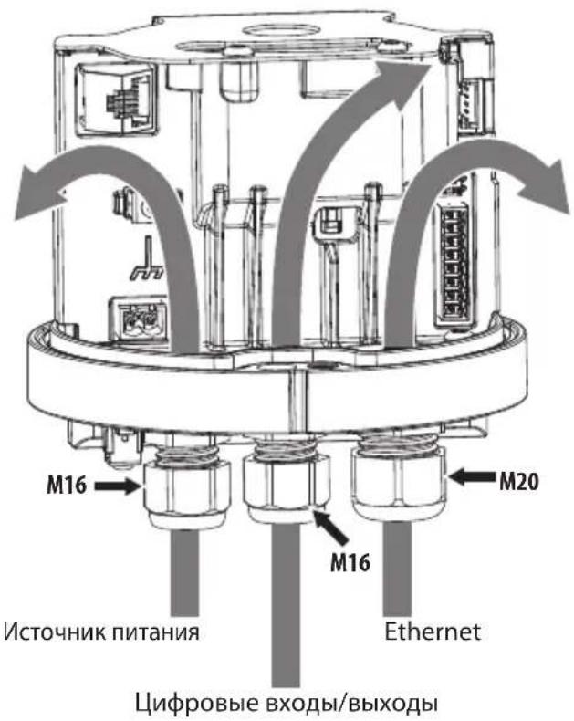
natural_image
Technical line drawing of a mechanical component with no visible text or symbolsnatural_image
Technical line drawing of a mechanical component with no visible text or symbolsnatural_image
Technical line drawing of a mechanical component with a highlighted part and an arrow indicating direction (no text or symbols present)Рис. 16
natural_image
Technical drawing of a mechanical component with two slots and a top section (no text or symbols)Рис. 20
natural_image
Technical diagram of a mechanical assembly with internal components and labeled part J6 (no readable text or symbols beyond label)Рис. 21
natural_image
Technical line drawing of a multi-pin electrical connector (no text or symbols)Рис. 22
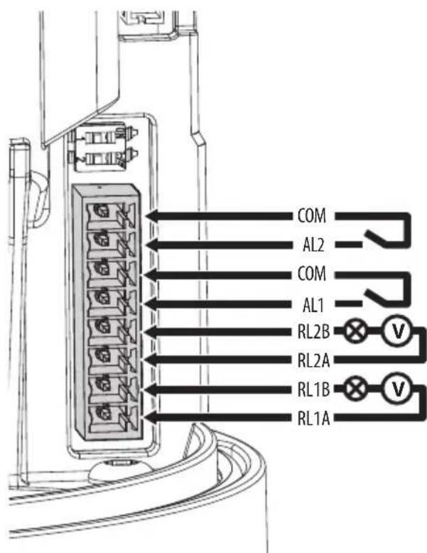
Рис. 23
natural_image
Technical line drawing of an internal mechanical assembly with no visible text or symbolsРис. 25
natural_image
Technical line drawing of a circular mechanical component with internal components and mounting holes (no text or symbols)Рис. 26
natural_image
Technical line drawing of a mechanical assembly with internal components and a directional arrow (no text or symbols)Рис. 27
natural_image
Technical line drawing of a mechanical component with no visible text or symbolsРис. 28
natural_image
Technical line drawing of a mechanical component with a highlighted section and arrow indicator (no text or symbols)Рис. 29
7 Включение

Рис. 30
Рис. 31
15.1.5 Cybersecurity
15.2.6 Cybersecurity
15.3.6 Cybersecurity
Indoor Flicker Reduction

Headquarters Italy VIDEOTEC s.r.l..
Via Friuli, 6 - I-36015 Schio (VI) - Italy
Tel. +39 0445 697411 - Fax +39 0445 697414
Email: info@videotec.com
www.videotec.com
- ULISSE EVO (UE)
- ULISSE EVO THERMAL (UET)
- ULISSE EVO DUAL (UED)
- Contents
- About this manual....7
- Notes on copyright and information on trademarks....7
- Safety rules ....7
- Product description and type designation....10
- Preparing the product for use....13
- Installation....14
- Switching on 28
- Configuration....29
- Accessories and Supports....29
- Technical drawings....47
- About this manual
- Typographical conventions
- DANGER!
- CAUTION!
- INFO
- Notes on copyright and information on trademarks
- Safety rules
- Product description and type designation
- Product overview
- Product marking label
- Model identification
- Preparing the product for use
- Safety precautions before use
- Unpacking
- Contents
- Safely disposing of packaging material
- Installation
- Installation options
- Viewing angles
- Installation with internal cable passage
- Installation with internal cable passage with product inverted
- Installation with quick connectors
- Installation with quick connectors with product inverted
- Typical connection of accessories
- Opening the base of the product
- Mounting the bracket
- Cable management
- Fixing the base to the support
- Sunshield mounting
- Fastening of the safety coupling
- Connector board description
- Connecting the power supply
- 24Vac/24Vdc power supply
- PoE 90W power supply
- PoH backward compatibility mode enabling
- Alarms and relays connections
- Tab. 6
- Ethernet cable connection
- The characteristics of the Ethernet cables can be consulted in the relevant chapter (15 Technical data, page 33).
- Installation of the upper body
- Switching on
- Configuration
- Default IP address
- Web interface
- First access to the web pages
- Accessories and Supports
- Instructions for normal operation
- Maintenance
- Routine maintenance
- Inspecting the cables
- Replacement of the wiper blade
- Extraordinary maintenance
- Reset to Factory Default Settings
- Cleaning
- Cleaning the window and external surfaces of the product
- Cleaning the germanium window
- Information on disposal and recycling
- Troubleshooting
- PROBLEM The product does not go on.
- PROBLEM The product does not go on. The LED indicated in the figure is off (Fig. 25, page 27).
- PROBLEM The shooting area do not correspond to the selected preset position.
- PROBLEM With the PoE power supply, the product blocks on the "Maintenance" screen and displays "Error 39".
- Technical data
- ULISSE EVO (UE)
- General
- Mechanical
- Electrical
- Ethernet cable features
- Network
- Cybersecurity
- Video
- Video analytics
- Cameras
- Illuminators
- LED illuminator
- UEIxxx
- UEIxxxP
- Automatic and remote switching on
- Environment
- For indoors and outdoors installation
- Operating temperature
- Wind resistance
- Certifications
- Certifications - Railway applications
- Certifications - Marine applications
- ULISSE EVO THERMAL (UET)
- General
- Mechanical
- Housing's window
- Electrical
- Network
- Cybersecurity
- Video
- Environment
- Certifications
- Certifications - Railway applications
- Certifications - Marine applications
- ULISSE EVO DUAL (UED)
- General
- Mechanical
- Housing's window
- Electrical
- Network
- Cybersecurity
- Video
- Day/Night camera
- Thermal Camera
- Video encoder
- Day/Night cameras
- SONY FCB-EV7520 Day/Night Full HD 30x
- Thermal Cameras
- Environment
- Certifications
- Certifications - Railway applications
- Technical drawings
- Sommario
- Accensione
- Telecamera Day/Night
- Telecamere Day/Night
- Sommaire
- Fixation du support
- Alimentation en PoE 90W
- Allumage
- Certifications - Applications ferroviaires
- Certifications - Applications ferroviaires
- Certifications - Applications ferroviaires
- Inhaltsverzeichnis
- Allgemeines....7
- Abb. 2
- AVERTISSEMENT!
- Einschaltung
- ATTENZIONE!
- Включение
- Рис. 31
Brand : Videotec
Model : ULISSE EVO THERMAL
Category : Surveillance Camera