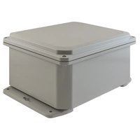
WASPT - Water pump Videotec - Free user manual and instructions
Find the device manual for free WASPT Videotec in PDF.


| Product Type | PTZ camera washer kit (water pump with tank) |
| Brand | Videotec |
| Model | WASPT |
| Tank capacity | 5 liters or 23 liters depending on version |
| Discharge height | 5 m, 11 m or 30 m depending on version |
| Dimensions (W x H x D) | 5L version: 217 x 280 x 257 mm; 23L version (5/11m): 301 x 430 x 348 mm; 23L version (30m): 301 x 640 x 348 mm |
| Net weight | 3.8 kg (5L); 5.5 kg (23L/5m); 6.7 kg (23L/11m); 16.7 kg (23L/30m) |
| Supply voltage | 230 Vac, 120 Vac or 24 Vac depending on version |
| Current consumption | 0.3 A to 4.5 A depending on version and voltage |
| Operating temperature | -25 °C to +60 °C (with antifreeze, depending on version) |
| Protection rating (IP) | IP66 (5m and 11m versions); IPX4 (30m version) |
| Materials | Polyethylene tank, stainless steel cage |
| Main functions | Pumping of washer fluid for PTZ camera; manual or remote activation via DTWRX card; automatic stop by level controller (11m and 30m versions) |
| Maintenance | Replacement of fuses (board and pump); external cleaning; tank drainage if not used |
| Safety instructions | Disconnect power before any intervention; use a 20A max bipolar circuit breaker; ground wire 10 mm longer |
| Available spare parts | Fuses (T 4A H 250V, T 2A L 250V, T 4A L 250V), optional DTWRX card, gasket kit |
| Repairability | Fuse replacement by user; other repairs by qualified personnel |
| Certifications | CE, EAC, FCC Part 15, Lloyd's Register (11m marine version) |
| Intended use | Outdoor PTZ camera window cleaning; intermittent operation (1 min ON, 15 min OFF) |
| Kit contents | Tank with pump, clamps, silicone sleeve, fittings, hose, brackets, semi-rigid tube with nozzle, screws, manual |
Frequently Asked Questions - WASPT Videotec
User questions about WASPT Videotec
0 question about this device. Answer the ones you know or ask your own.
Ask a new question about this device
Download the instructions for your Water pump in PDF format for free! Find your manual WASPT - Videotec and take your electronic device back in hand. On this page are published all the documents necessary for the use of your device. WASPT by Videotec.
USER MANUAL WASPT Videotec
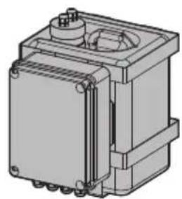
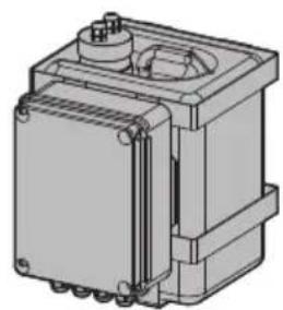
Washer pump and 5 or 23 litre tank
natural_image
Technical line drawing of a mechanical component with no visible text or symbols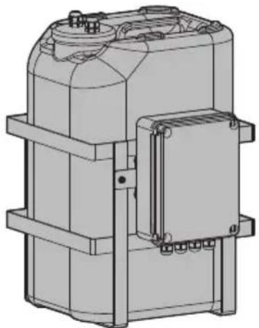
natural_image
Technical line drawing of a mechanical device with mounting brackets and housing (no text or symbols)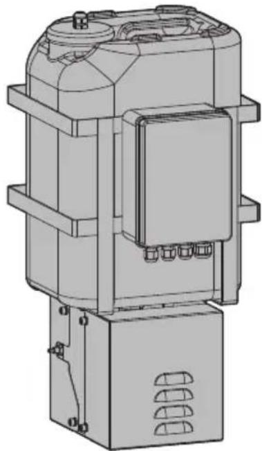
natural_image
Technical line drawing of a mechanical device with no visible text or symbolsEN English - Instruction manual
IT Italiano - Manuale di istruzioni
FR Français - Manuel d'instructions
DE Deutsch - Bedienungsanleitung
RU Русский - Руководство по эксплуатации
WASPT
Washer pump and 5 or 23 litre tank
natural_image
Technical line drawing of a mechanical component with no visible text or symbols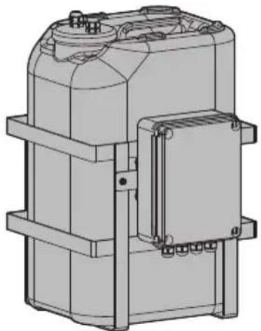
natural_image
Technical line drawing of a mechanical device with mounting brackets and housing (no text or symbols)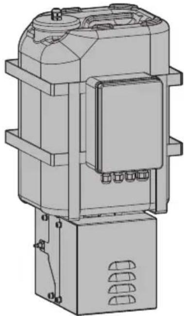
natural_image
Technical line drawing of a mechanical device with no visible text or symbolsContents
1 About this manual....5
1.1 Typographical conventions .... 5
2 Notes on copyright and information on trademarks....5
3 Safety rules ....5
4 Product description and type designation....6
4.1 Product marking label....6
5 Preparing the product for use....6
5.1 Unpacking....6
5.2 Contents 6
5.3 Opening of the 30m delivery head pump casing....6
5.4 Safely disposing of packaging material....6
6 Installation....7
6.1 Fastening of the metal cage....7
6.2 Choosing the power supply....8
6.3 Open the box....8
6.4 Board description....8
6.5 Connection of the board....9
6.5.1 Installing the fuse....9
6.5.1.1 Pump with 5m (16ft) or 11m (36ft) delivery....9
6.5.1.2 Pump with 30m (98ft) delivery....9
6.5.2 Connection of the PTZ camera or stand-alone housing 9
6.5.3 Pump manual activation....11
6.5.4 Wiper connection 11
6.5.5 Wiper manual activation....11
6.5.6 Remote control with DTWRX optional board 11
6.5.7 Connecting the power supply 12
6.6 Pump installation....12
6.6.1 Adjustment of the level switch position....12
6.6.2 Pump with 5m (16ft) delivery....13
6.6.3 Pump with 11m (36ft) delivery....13
6.6.4 Pump with 30m (98ft) delivery....13
6.7 Washer installation (ULISSE range)....14
6.8 Washer installation (ULISSE2) 15
6.9 Washer installation (ULISSE COMPACT range)....16
6.10 Washer installation (ULISSE EVO range).... 16
6.10.1 Washer installation on the PTZ camera 16
6.10.2 Washer installation on the overturned PTZ camera....17
6.11 Washer installation (NVX range)....18
6.12 Washer installation (NXPTZ SERIES2 range) 19
6.13 Examples of washer installation....20
7 Maintenance 21
7.1 Extraordinary maintenance (to be done only under particular circumstances)....21
7.1.1 Fuses replacement....21
7.1.1.1 Replacing the fuse of the pump board 21
7.1.1.2 Replacing the fuse on the pump inlet.... 21
8 Information on disposal and recycling 21
9 Technical data....22
9.1 Washer kit, tank of 5l (1.3gal), pump with 5m (16ft) delivery head....22
9.1.1 Mechanical....22
9.1.2 Electrical....22
9.1.3 Environment....22
9.1.4 Certifications 22
9.2 Washer kit, tank of 23l (6gal), pump with 5m (16ft) delivery head....22
9.2.1 Mechanical....22
9.2.2 Electrical 22
9.2.3 Environment 22
9.2.4 Certifications....22
9.3 Washer kit, tank of 23l (6gal), pump with 11m (36ft) delivery head....23
9.3.1 Mechanical....23
9.3.2 Electrical 23
9.3.3 Environment 23
9.3.4 Certifications....23
9.3.5 Certifications - Marine applications....23
9.4 Washer kit, tank of 23l (6gal), pump with 30m (98ft) delivery head ....23
9.4.1 Mechanical....23
9.4.2 Electrical 23
9.4.3 Environment....23
9.4.4 Certifications....23
10 Technical drawings....24
1 About this manual
Read all the documentation supplied carefully before installing and using this product. Keep the manual in a convenient place for future reference.
1.1 Typographical conventions

DANGER!
High level hazard.
Risk of electric shock. Disconnect the power supply before proceeding with any operation, unless indicated otherwise.

DANGER!
Hot surface.
Avoid contact. Surfaces are hot and may cause personal injury if touched.

CAUTION!
Medium level hazard.
This operation is very important for the system to function properly. Please read the procedure described very carefully and carry it out as instructed.

INFO
Description of system specifications.
We recommend reading this part carefully in order to understand the subsequent stages.
2 Notes on copyright and information on trademarks
The mentioned names of products or companies are trademarks or registered trademarks.
3 Safety rules

CAUTION! The electrical system to which the unit is connected must be equipped with a 20A max automatic bipolar circuit breaker. The minimum distance between the circuit breaker contacts must be 3mm (0.1in). The circuit breaker must be provided with protection against the fault current towards the ground (differential) and the overcurrent (magnetothermal).

CAUTION! Device installation and maintaining must be performed by specialist technical staff only.
- The manufacturer declines all responsibility for any damage caused by an improper use of the appliances mentioned in this manual. Furthermore, the manufacturer reserves the right to modify its contents without any prior notice. The documentation contained in this manual has been collected and verified with great care. The manufacturer, however, cannot take any liability for its use. The same thing can be said for any person or company involved in the creation and production of this manual.
- Before starting any operation, make sure the power supply is disconnected.
- Be careful not to use cables that seem worn or old.
- Never, under any circumstances, make any changes or connections that are not shown in this handbook. Improper use of the appliance can cause serious hazards, risking the safety of personnel and of the installation.
- Use only original spare parts. Non-original spare parts could cause fire, electrical discharge or other hazards.
- Before proceeding with installation, check the supplied material to make sure it corresponds to the order specification by examining the identification labels (4.1 Product marking label, page 6).
- A power disconnect device must be included in the electrical installation, and it must be very quickly recognizable and operated if needed.

4 Product description and type designation
The Videotec WASPT is a wash kit consisting of a water tank with an integrated pump for PTZ cameras and camera housings equipped with wiper.
This wide range of wash kits comes in capacities from 5 to 23 litres and delivery heads of up to 30 metres.
The optional DTWRX card enables remote control (via RS-485) of the wiper and the washer pump if used with a stand-alone housing.
The versions with 11m and 30m delivery head have a level switch for automatic stoppage of the pump.
The 30m (98ft) delivery head versions are only available in 230Vac or 120Vac.
Using the anti-freeze liquid, the minimum operating temperature (versions with 5m (16ft) and 11m (36ft) delivery heads) can reach as low as -25°C (-13°F).
4.1 Product marking label
See the label attached to the product.
5 Preparing the product for use

Any change that is not expressly approved by the manufacturer will invalidate the warranty.
5.1 Unpacking
When the product is delivered, make sure that the package is intact and that there are no signs that it has been dropped or scratched.
If there are obvious signs of damage, contact the supplier immediately.
When returning a faulty product we recommend using the original packaging for shipping.
Keep the packaging in case you need to send the product for repairs.
5.2 Contents
Check the contents to make sure they correspond with the list of materials as below:
- Glass wash system
- Cable ties
- Silicone sheath
- Hydraulic joints
• Supports for the supply tube - Locking bracket of the delivery pipe
- Delivery pipe
- Washer semi-rigid pipe (with nozzle)
- Bolts and screws
- Instruction manual
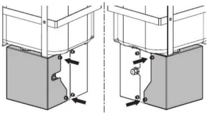
5.3 Opening of the 30m delivery head pump casing
The side casing must be dismantled for any removal or replacement operation of the tank. Unscrew the 4 screws and remove the casing.
natural_image
Technical diagram showing two mechanical assembly configurations with arrows indicating force or movement (no text or symbols present)Fig. 1
5.4 Safely disposing of packaging material
The packaging material can all be recycled. The installer technician will be responsible for separating the material for disposal, and in any case for compliance with the legislation in force where the device is to be used.
6 Installation

Install the pump with 30m (98ft) pressure head in places protected from heavy rain.

The device should be assembled vertically. Any other position could impair the performance of the device.
6.1 Fastening of the metal cage

Take special care when attaching and fastening down the apparatus. If it is to be attached to a concrete surface you must use dowel pins with a traction torque rating of at least 0.4kN each. You are advised to use screws with a 6mm diameter and at least 50mm long. If the surface is metal, use M8 class A4-70 screws and with such a length to guarantee at least 6 rotations of the held thread. The fastening system must be capable of supporting at least 4 times the weight of the entire equipment, including the tank completely full of water.

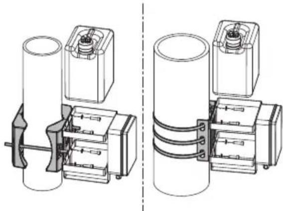
For the version with 5 litre tank only, fastening is possible on a pole using the specific accessories.
natural_image
Technical line drawing of two mechanical components with no visible text or symbolsFig. 2
Take the plug out of the tank, along with any pumps and level gauges. Remove the tank from the metal cage.
Attach the metal cage (01) firmly to a wall using the holes provided for this (02).
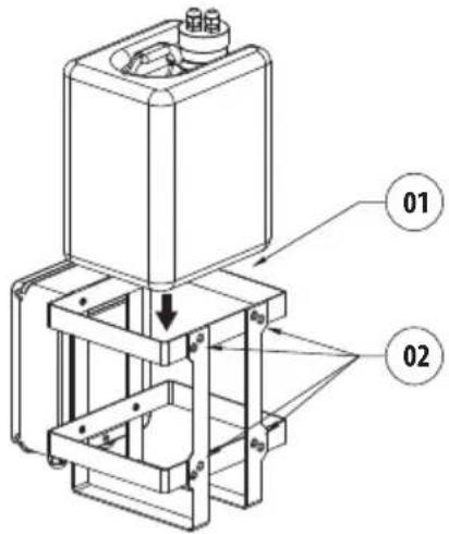
Fig. 3 Water tank 5l (1.3gal), 5m (16ft) delivery.
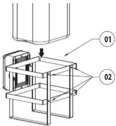
Fig. 4 Water tank 23l (6gal), 5m (16ft) or 11m (36ft) delivery.
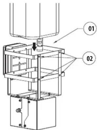
Fig. 5 Water tank 23l (6gal), 30m (98ft) delivery.
6.2 Choosing the power supply
Depending on the version, the device can be provided with different power supply voltages. Their value is shown on the product identification label.

Electrical connections must be performed with the power supply disconnected and the circuit-breaker open.

When commencing installation make sure that the specifications for the power supply for the installation correspond with those required by the device.

Check that the power supply socket and cable are adequately dimensioned.

Use a power cable that is suitable for outdoor use (example: H05RH-F).
6.3 Open the box
Open the cover of the water-proof box and connect as described below.
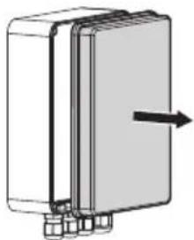
natural_image
Diagram of a rectangular device with internal components and an arrow indicating direction (no text or symbols)Fig. 6
6.4 Board description
| BOARD DESCRIPTION | |
| Connector Function | |
| J1 Power supply for the board | |
| J7 Wiper | |
| J8 Optional board (DTWRX) | |
| J9 I/O management and pump functions | |
| FUS1 Power supply selection fuse (230Vac) | |
| FUS2 Power supply selection fuse (120Vac) | |
| FUS3 Power supply selection fuse (24Vac) | |
Tab. 1
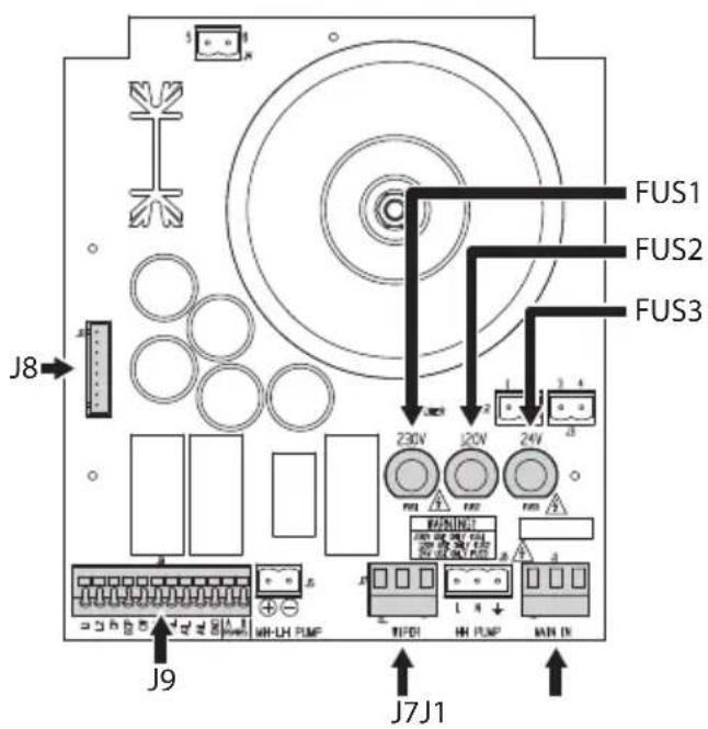
Fig. 7
6.5 Connection of the board

Electrical connections must be performed with the power supply disconnected and the circuit-breaker open.
6.5.1 Installing the fuse
6.5.1.1 Pump with 5m (16ft) or 11m (36ft) delivery

Depending on the power supply voltage choose the right fuse holder.
The board is supplied with the fuse in the following position: FUS1, 230Vac (6.4 Board description, page 8).
6.5.1.2 Pump with 30m (98ft) delivery
Depending on the type of power supply, the board is supplied with the fuse in the correct position: FUS1, 230Vac or FUS2, 120Vac (6.4 Board description, page 8).
6.5.2 Connection of the PTZ camera or stand-alone housing

All the connections of terminal J9 must have very low safety voltage (sources of electrical energy class 1 (ES1)).

The AVL, GND, A1L and A2L contacts can only be used in pump models equipped with floats. If active, the AVL alarm supplies an output voltage between 12Vdc and 20Vdc. Contacts rated current: 4A max.
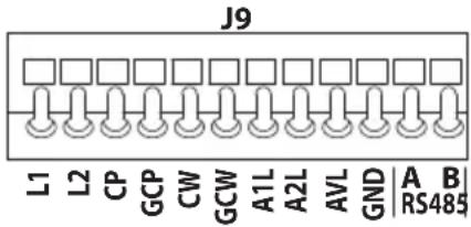
Fig. 8
Connect the PTZ camera or the stand-alone housing to the terminal contacts (J9, 6.4 Board description, page 8).
For connection, use the table outlined below as a reference.

Nominal section of the cables used: from 0.5mm^2 (20AWG) up to 1.5mm^2 (15AWG).
EN - English - Instruction manual
| DESCRIPTION OF CONTACTS | ||||||||||
| Contact | Description | ULISSE | ULISSE NETCAM/ULISSE RADICAL | ULISSE2 | ULISSE COMPACT | ULISSE COMPACT DELUX | ULISSE EVO | NVX | NXPTZ/NXPTZT | NXPTZ DELUX/NXPTZ SERIES2/NXPTZR SERIES2/NXPTZT SERIES2 |
| L1 Level switch | Do not use | |||||||||
| L2 | ||||||||||
| CP | Pump activation (dry contact) | O1 | O1 | RL2A | R2A | R1A | RL2A | CONN 1, (pin 1) | Cable: Green-Brown | Cable: Green-Brown |
| GCP | GND pump activation (dry contact) | C1 | C1 | RL2B | R2B | R1B | RL2B | CONN 1, (pin 2) | Cable: Green-White | Cable: Green-White |
| CW Wiper activation (dry contact) Refer to chapter: 6.5.5 Wiper manual activation | manual activation | |||||||||
| GCW GND wiper activation (dry contact) | ||||||||||
| A1L | Liquid level alarm output (dry contact) | - | Alarm x^1 | ALx^1 | - | A | AL1 | - | - | Cable: Brown |
| A2L | Liquid level alarm output (dry contact) | - | ALARMS | COM | - | G | COM | - | - | Cable: Green |
| AVL Liquid level alarm output (controlled when powered) | ALx^1 | - | - | W | - | - | - | Cable: Black | - | |
| GND | GND liquid level alarm output (controlled when powered) | COM/AGND | - | - | G | - | - | - | Cable: Green | - |
| RS485-A | Connect the serial line RS-485-A (+) coming from the control system | Refer to chapter: 6.5.6 Remote control with DTWRX optional board | ||||||||
| RS485-B | Connect the serial line RS-485-B (-) coming from the control system | |||||||||
^1 Any one of the alarm inputs available.
Tab. 2
6.5.3 Pump manual activation

If the PTZ camera is used combined with the wash system, ignore the instructions below and follow those in the relevant manual.

Use cables with the characteristics outlined below.
• Minimum section: 0.5mm ^2 (20AWG).
• Maximum length: 1000m.
Manual activation of the pump takes place by short-circuiting the (by closing a button, relay, etc.) CP and GCP dry contacts. Manual stoppage of the pump takes place by opening the CP and GCP dry contacts.
Refer to the terminal contacts (J9, Fig. 8, page 9).
6.5.4 Wiper connection

The voltage supplied to the J7 (WIPER) terminal is equal to that applied to the power supply terminal of the washer pump. Use a wiper having electric characteristics that are suitable for the power supply voltage.
Contacts rated current: 6A max.

If the PTZ camera has a wiper, ignore the instructions below and follow those in the relevant manual.
Connect the wiper to the connector (J7, 6.4 Board description, page 8).
Respect the order of the contacts PERM, SW and COM (refer to the wiper manual).
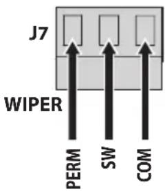
Fig. 9

Nominal section of the cables used: from 0.2mm^2 (24AWG) up to 2.5mm^2 (13AWG).
6.5.5 Wiper manual activation

If the PTZ camera has a wiper, ignore the instructions below and follow those in the relevant manual.

Use cables with the characteristics outlined below.
• Minimum section: 0.5mm ^4 (20AWG).
• Maximum length: 1000m.
Manual activation of the wiper takes place by short-circuiting the (by closing a button, relay, etc.) CW and GCW dry contacts. Manual stoppage of the wiper takes place by opening the CW and GCW dry contacts.
Refer to the terminal contacts (J9, Fig. 8, page 9).
6.5.6 Remote control with DTWRX optional board

If the PTZ camera is used combined with the wash system, ignore the instructions below and follow those in the relevant manual.
The optional DTWRX card enables remote activation of the wiper and the pump via RS-485.
Insert the board in the connector (J8, 6.4 Board description, page 8). Refer to the terminal contacts (J9, Fig. 8, page 9).
The possible configurations of the optional card and the control system are described in the respective manuals.
6.5.7 Connecting the power supply

Earth cable should be about 10mm longer than the other two, so that it will not be disconnected accidentally if pulled.

The power supply cable must be covered by the silicone sheath (01) supplied. The silicone sheath must be fastened with the corresponding cable tie (02).

All the conductors relating to the MAIN-IN, HH-PUMP and WIPER terminals must be separated from the other safety very low voltage circuits (ES1 circuits).
The disconnection of a wire must not compromise the protection against electric shocks.
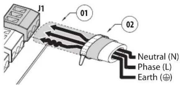
Fig. 10
Connect the power supply terminal (J1, 6.4 Board description, page 8). Connection must be carried out using a cable of adequate section.

Nominal section of the cables used: from 0.2mm ^2 (24AWG) up to 2.5mm ^2 (13AWG).
6.6 Pump installation

Be very careful not to start the pump when the tank is empty.

We recommend filling the tank with water at ambient temperature. If using the pump at temperatures below 3^ C ( 37.4^ F) add some glass cleaner antifreeze liquid to the water.

The antifreeze liquid will cause irreparable damage to the germanium windows. In this case, do not use anti-freeze liquid, but add ethanol in a 20% solution.

If present, the level switch enables automatic stoppage of the pump.
6.6.1 Adjustment of the level switch position
In the equipped versions, the position of the level switch (01) and the counterweight (02) must be adjusted.
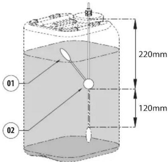
Fig. 11

The overall length of the level switch cable inserted in the tank must be approx. 340mm.
6.6.2 Pump with 5m (16ft) delivery
Fill the tank with water and insert it in the metal cage.
Insert the pump in the tank and close the cap.
The system is ready to be powered.
6.6.3 Pump with 11m (36ft) delivery
Adjust the level switch (6.6.1 Adjustment of the level switch position, page 12).
Fill the tank with water and insert it in the metal cage.
Insert the pump and the level switch in the tank and close the cap.
The system is ready to be powered.
6.6.4 Pump with 30m (98ft) delivery

Avoid contact with the delivery hose coupling of the pump. Hot surfaces may cause personal injury if touched.
Adjust the level switch (6.6.1 Adjustment of the level switch position, page 12).
Fill the tank with water and insert it in the metal cage.
Ensure that the male/female hydraulic joint (01) is inserted correctly. Insert the level switch in the tank and close the cap. Check the delivery hose coupling of the pump (02) to make sure a small quantity of water comes out.
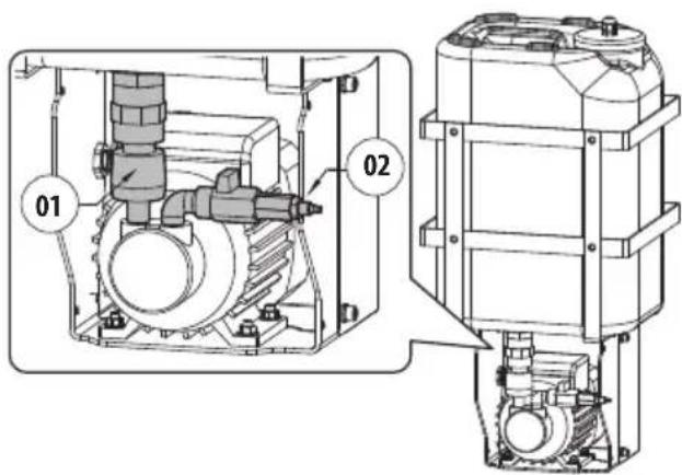
Fig. 12
Unscrew the knurled nut (01) from the delivery joint (02). Insert the knurled nut on the delivery pipe (03). Insert the end of the delivery pipe into the spinner (04). Lock the nut to the coupling.
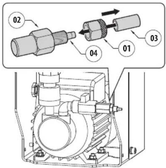
Fig. 13
At the end of the installation operations, re-assemble the casing working in the reserve order (5.3 Opening of the 30m delivery head pump casing, page 6).

Pay attention to the fixing. Tightening torque: 7Nm.
The system is ready to be powered.
6.7 Washer installation (ULISSE range)

To fasten the base to the support, use the screws (05), the washers (06), the gaskets for screws (07) and the gasket (08).

Installation examples (6.13 Examples of washer installation, page 20).
Having fastened the support (01), arrange the washer pipe support (supplied with the PTZ camera) (03) in the desired position.
Insert the cables inside the support so that they protrude by about 50cm. Insert the cable in the cable glands (02). Keeping the base (04) at about 20cm (7.9in) from the support, lock the cable glands. Set the base up on the stand arranging the cables inside.
Fasten the base on the support using the screws supplied with the PTZ camera (05).
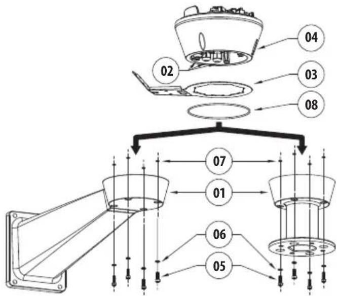
Fig. 14
Cut the cables to size and either restore or make the connections to the positioning unit.
Shorten the semi-rigid washer pipe (01) as needed. Unscrew the nut (02) from the joint and slide it along the pipe. Insert the end of the pipe into the ogive (03).
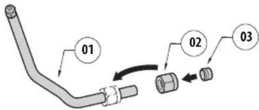
Fig. 15
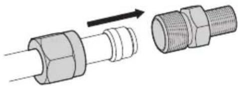
Lock the nut to the coupling.
natural_image
Diagram showing two types of pipe fittings: a cylindrical connector and a threaded pipe fitting, with no text or symbols present.Fig. 16
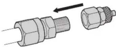
Tighten the delivery joint.
natural_image
Technical illustration of two connected pipe connectors with a directional arrow indicating assembly (no text or symbols)Fig. 17
Unscrew the knurled nut (01) from the delivery joint (02). Insert the knurled nut on the delivery pipe (03). Insert the end of the delivery pipe into the spinner (04). Lock the nut to the coupling.
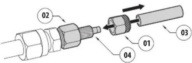
Fig. 18
Fasten the pipe to the washer support using the bracket (01), the screws (02) and the washers (03) supplied with the PTZ camera.
Block the joint using the clip (04) supplied with the PTZ camera.

Fig. 19
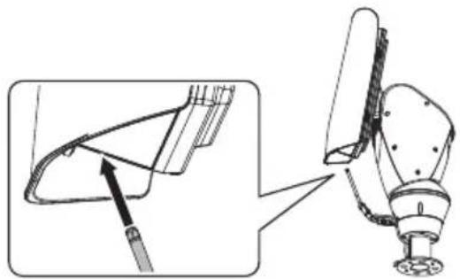
To calibrate the jet, orientate the nozzle towards the window of the housing.
natural_image
Technical illustration of a robotic arm joint with a close-up inset showing the mechanism (no text or symbols present)Fig. 20
To start the wash system refer to the PTZ camera manual.
6.8 Washer installation (ULISSE2)

Installation examples (6.13 Examples of washer installation, page 20).
Position the nozzle support bracket (01) in the appropriate groove (02) on the base and lock it using the screws and washers (03). Dismantle the nozzle (04) from the semi-rigid pipe on the washer supplied. Position the nozzle and lock it using washer and nut (05). Install the gasket (06) on the bottom hole on the bracket. Pass the delivery pipe (07) through the gasket and connect it to the nozzle.
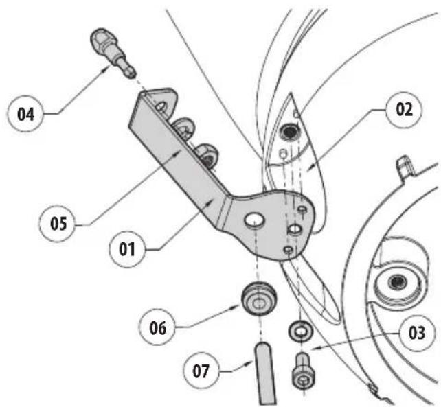
Fig. 21
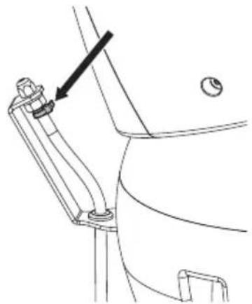
Secure the delivery pipe using the provided cable tie.
natural_image
Technical line drawing of a mechanical assembly with a bracket and mounting bracket (no text or symbols)Fig. 22 Final washing position.
To start the wash system refer to the PTZ camera manual.
6.9 Washer installation (ULISSE COMPACT range)

Installation examples (6.13 Examples of washer installation, page 20).
Position the nozzle support bracket (01) in the appropriate groove (02) on the base and lock it using the 2 screws (03). Dismantle the nozzle (04) from the semi-rigid pipe on the washer supplied. Position the nozzle and lock it using washer and nut (05). Install the gasket (06) on the bottom hole on the bracket. Pass the delivery pipe (07) through the gasket and connect it to the nozzle.
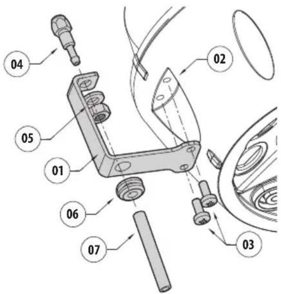
Fig. 23
Secure the delivery pipe using the provided cable tie.
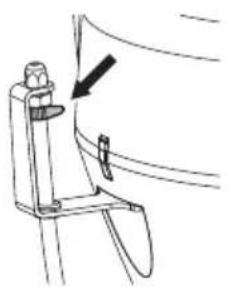
natural_image
Line drawing of a mechanical component with a knob and arrow indicating direction (no text or symbols)Fig. 24 Final washing position.
To start the wash system refer to the PTZ camera manual.
6.10 Washer installation (ULISSE EVO range)

Installation examples (6.13 Examples of washer installation, page 20).
6.10.1 Washer installation on the PTZ camera
Remove the nozzle (01) from the semi-rigid pipe on the washer supplied. Position the nozzle in the bracket and fasten it with the washer and the nut (02). Assemble the gasket (03) on the lower part of the bracket. Pass the delivery pipe (04) through the gasket and connect it to the nozzle.
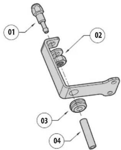
Fig. 25
Fasten the delivery pipe to the nozzle using the clip supplied.
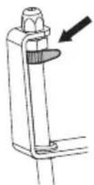
Fig. 26
Identify the groove with the positioning pin (05) for fastening the bracket of the nozzle (07). Remove the fastening screw (06). Position the bracket of the nozzle (07) using the positioning pin (05) and fasten it with the previously removed screw (06). Refer to the PTZ camera manual for the tightening torque of the screw.
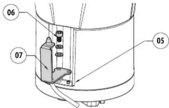
Fig. 27
To start the wash system refer to the PTZ camera manual.
6.10.2 Washer installation on the overturned PTZ camera
Shorten the semi-rigid washer pipe (01) as needed. Unscrew the nut (02) from the joint and slide it along the pipe. Insert the end of the pipe into the ogive (03).
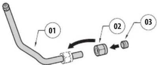
Fig. 28
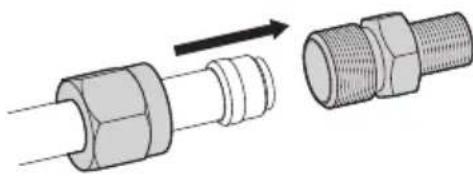
Lock the nut to the coupling.
natural_image
Diagram showing two mechanical components with a directional arrow indicating motion (no text or symbols present)Fig. 29
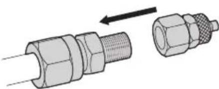
Tighten the delivery joint.
natural_image
Technical illustration of two connected pipe connectors with a directional arrow indicating assembly (no text or symbols)Fig. 30
Unscrew the knurled nut (04) from the delivery joint (05). Insert the knurled nut on the delivery pipe (06). Insert the end of the delivery pipe into the spinner (07). Lock the nut to the coupling.
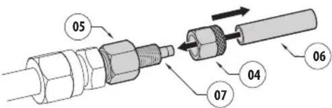
Fig. 31
Identify the groove with the positioning pin (08) for fastening the bracket of the nozzle (10). Remove the fastening screw (09). Position the bracket of the nozzle (10) using the positioning pin (08) and fasten it with the previously removed screw (09). Refer to the PTZ camera manual for the tightening torque of the screw.
Insert two metal clips (11) in the bracket (10), insert the semi-rigid pipe (12) between the clips and tighten the screws of the two clips.
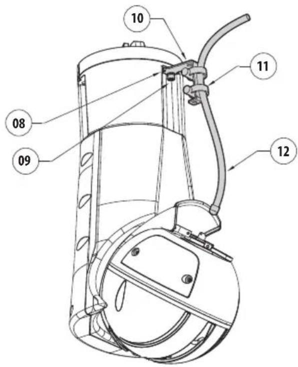
Fig. 32
To calibrate the jet, orientate the nozzle towards the window of the PTZ camera.
To start the wash system refer to the PTZ camera manual.
6.11 Washer installation (NVX range)

Installation examples (6.13 Examples of washer installation, page 20).
The product, if equipped with a wiper, can be equipped with an external pump that provides water to clean the glass.
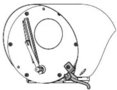
natural_image
Technical line drawing of a mechanical device with a circular housing and clamping tool (no text or symbols)Fig. 33
To complete installation of the washing system, use the kit supplied with the camera.
Insert the head of the nozzle (01) on the support (02) by tightening the nut (03).
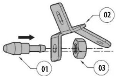
Fig. 34
Fasten the nozzle and the support assembled by using one of the accessory holes (01) on the front of the housing. Tighten the screw and the washer (02). Insert the delivery pipe of the nozzle (03). Secure the delivery pipe to the support with a clip (04).
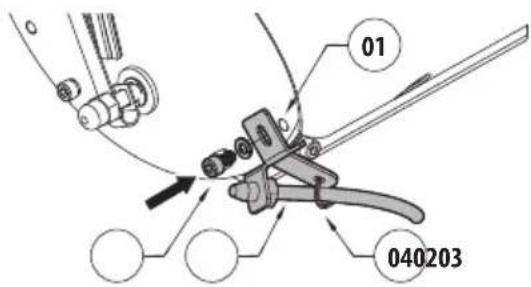
Fig. 35
To start the wash system refer to the camera manual.
6.12 Washer installation (NXPTZ SERIES2 range)

Installation examples (6.13 Examples of washer installation, page 20).
Fasten the support (01) onto the body of the PTZ with the metal clip (02) supplied with the PTZ camera.
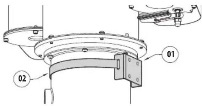
Fig. 36
Shorten the semi-rigid washer pipe (01) as needed. Unscrew the nut (02) from the joint and slide it along the pipe. Insert the end of the pipe into the ogive (03).
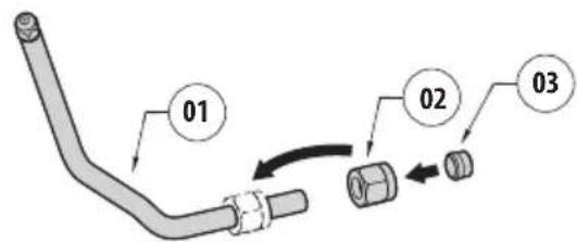
Fig. 37
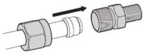
Lock the nut to the coupling.
natural_image
Diagram showing two types of pipe fittings: a cylindrical connector and a threaded connector, with no text or symbols present.Fig. 38
Tighten the delivery joint.
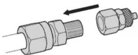
natural_image
Technical illustration of two connected mechanical connectors with a directional arrow indicating assembly (no text or symbols present)Fig. 39
Unscrew the knurled nut (01) from the delivery joint (02). Insert the knurled nut on the delivery pipe (03). Insert the end of the delivery pipe into the spinner (04). Lock the nut to the coupling.
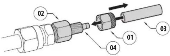
Fig. 40
Fasten the semi-rigid pipe (01) to the washer support using the plate (02), the screws (03) and the washers (04) supplied with the PTZ camera.
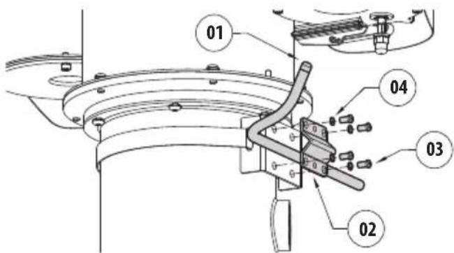
Fig. 41
To calibrate the jet, orientate the nozzle towards the window of the PTZ camera.
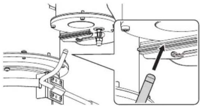
natural_image
Technical diagram of a mechanical assembly with no visible text or symbolsFig. 42
To start the wash system refer to the PTZ camera manual.
6.13 Examples of washer installation
EN - English - Instruction manual
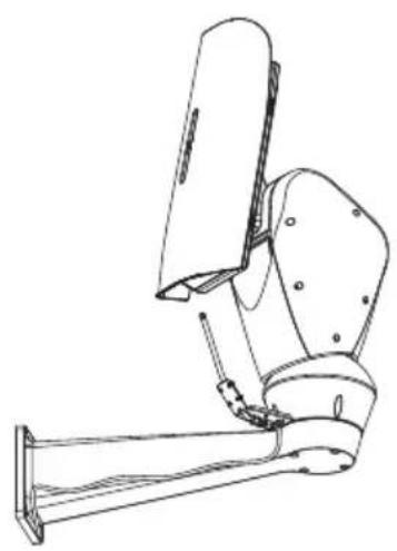
natural_image
Technical line drawing of a mechanical device with articulated joints and mounting base (no text or symbols)Fig. 43 Example of washer installation on the PTZ camera.
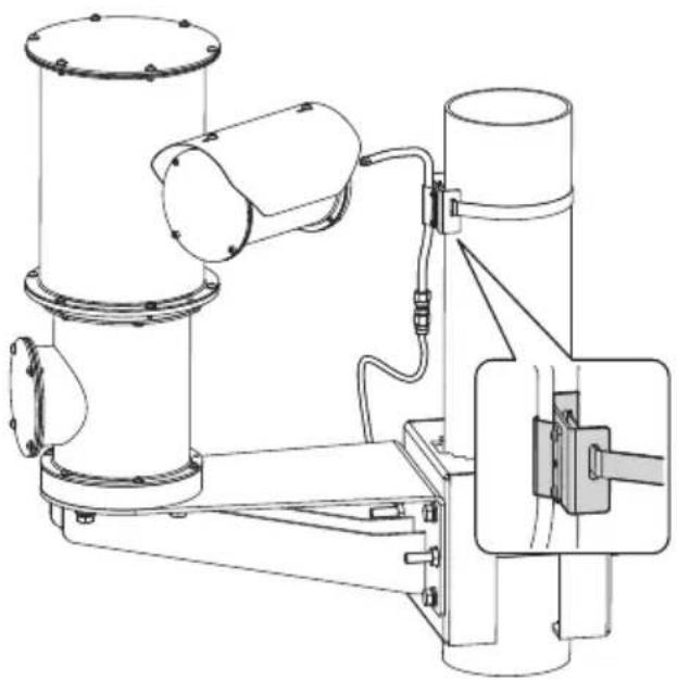
natural_image
Technical line drawing of a mechanical device with cylindrical components and wiring (no text or symbols)Fig. 45 Example of washer installation on pole.
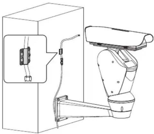
natural_image
Technical line drawing of a robotic arm mounted on a cabinet, showing wiring and components (no text or symbols)Fig. 44 Example of washer installation on wall.
7 Maintenance

CAUTION! Device installation and maintaining must be performed by specialist technical staff only.
7.1 Extraordinary maintenance (to be done only under particular circumstances)
7.1.1 Fuses replacement

Maintenance must be performed with the power supply disconnected and the circuit-breaker open.

Check the causes that caused the fuse breakage. In the event the problem occurs again, contact the technical assistance service.
7.1.1.1 Replacing the fuse of the pump board
If necessary, the board's fuse can be replaced (6.5.1 Installing the fuse, page 9). The new fuse must comply with the directions given in the table.
| FUSE REPLACEMENT | ||
| Model Number Alternative 1 Alternative 2 | ||
| T 4A H 250V 5x20 BUS | SMANNS505-4-R | OMEGAGT520240 |
Tab. 3
As an alternative, use an approved fuse featuring the same characteristics.
7.1.1.2 Replacing the fuse on the pump inlet

The operation is performed only for a pump with a 5m or 11m delivery head.
Once the box is open identify the fuse position.
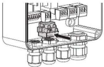
natural_image
Technical diagram of a mechanical assembly with no visible text or symbolsFig. 46
If necessary, the pump input fuse can be replaced. The new fuse must comply with the directions given in the table.
| FUSE REPLACEMENT | ||
| Model Number Alternative 1 Alternative 2 | ||
| Pump with 5m (16ft) delivery | ||
| T 2A L 250V 5x20 BUS | SMANNS506-2-R | OMEGAST522220 |
| Pump with 11m (36ft) delivery | ||
| T 4A L 250V 5x20 BUS | SMANNS506-4-R | OMEGAST522240 |
Tab. 4
As an alternative, use an approved fuse featuring the same characteristics.
8 Information on disposal and recycling
The European Directive 2012/19/EU on Waste Electrical and Electronic Equipment (WEEE) mandates that these devices should not be disposed of in the normal flow of municipal solid waste, but they should be collected separately in order to optimize the recovery stream and recycling of the materials that they contain and to reduce the impact on human health and the environment due to the presence of potentially hazardous substances.
The symbol of the crossed out bin is marked on all products to remember this.
The waste may be delivered to appropriate collection centers, or may be delivered free of charge to the distributor where you purchased the equipment at the time of purchase of a new equivalent or without obligation to a new purchase for equipment with size smaller than 25cm (9.8in).
For more information on proper disposal of these devices, you can contact the responsible public service.
9 Technical data

The product has been designed to work intermittently.
1 minute: ON. 15 minutes: OFF.
9.1 Washer kit, tank of 5l (1.3gal), pump with 5m (16ft) delivery head
9.1.1 Mechanical
Polyethylene tank, stainless steel cage
Dimensions (WxHxL): 217x280x257mm
(8.5x11x10.1in)
Cable glands: 1xM20 + 3xM16
Unit weight: 3.8kg (8.4lb)
Water tank capacity: 5l (1.3gal)
9.1.2 Electrical
Supply voltage/Current consumption:
• 230Vac, 0.3A, 50/60Hz
• 120Vac, 0.6A, 50/60Hz
• 24Vac, 1.8A, 50/60Hz
9.1.3 Environment
Operating temperature
• Maximum temperature: 60°C (140°F)
- Minimum temperature with antifreeze liquid in solution: -10^ (14°F)
- Minimum temperature with antifreeze liquid in solution (reduced performance and delivery height): -25°C (-13°F)
9.1.4 Certifications
Electrical safety (CE): EN60950-1, EN62368-1
Electromagnetic compatibility (CE): EN50130-4, EN61000-6-3, EN55032 (Class B), FCC Part 15 (Class B)
Outdoor installation (CE): EN60950-22
IP protection degree (EN60529):
• IP66
EAC certification
9.2 Washer kit, tank of 23l (6gal), pump with 5m (16ft) delivery head
9.2.1 Mechanical
Polyethylene tank, stainless steel cage
Dimensions (WxHxL): 301x430x348mm
(11.8×16.9×13.7in)
Cable glands: 1xM20 + 3xM16
Unit weight: 5.5kg (12.1lb)
Water tank capacity: 23l (6gal)
9.2.2 Electrical
Supply voltage/Current consumption:
• 230Vac, 0.3A, 50/60Hz
• 120Vac, 0.6A, 50/60Hz
- 24Vac, 1.8A, 50/60Hz
9.2.3 Environment
Operating temperature
• Maximum temperature: 60°C (140°F)
- Minimum temperature with antifreeze liquid in solution: -10^ (14°F)
- Minimum temperature with antifreeze liquid in solution (reduced performance and delivery height): -25°C (-13°F)
9.2.4 Certifications
Electrical safety (CE): EN60950-1, EN62368-1
Electromagnetic compatibility (CE): EN50130-4, EN61000-6-3, EN55032 (Class B), FCC Part 15 (Class B)
Outdoor installation (CE): EN60950-22
IP protection degree (EN60529):
• IP66
EAC certification
9.3 Washer kit, tank of 23l (6gal), pump with 11m (36ft) delivery head
9.3.1 Mechanical
Polyethylene tank, stainless steel cage
Dimensions (WxHxL): 301x430x348mm (11.8x16.9x13.7in)
Cable glands: 1xM20 + 3xM16
Unit weight: 6.7kg (14.8lb)
Water tank capacity: 231 (6gal)
Float level switch
9.3.2 Electrical
Supply voltage/Current consumption:
• 230Vac, 0.5A, 50/60Hz
• 120Vac, 1A, 50/60Hz
• 24Vac, 3.8A, 50/60Hz
Alarm outputs:
- Auto-powered: 1
- Dry contact: 1
9.3.3 Environment
Operating temperature
• Maximum temperature: 60°C (140°F)
- Minimum temperature with antifreeze liquid in solution: -10^ (14°F)
- Minimum temperature with antifreeze liquid in solution (reduced performance and delivery height): -25°C (-13°F)
9.3.4 Certifications
Electrical safety (CE): EN60950-1, EN62368-1
Electromagnetic compatibility (CE): EN50130-4, EN61000-6-3, EN55032, (Class B), FCC Part 15 (Class B)
Outdoor installation (CE): EN60950-22
IP protection degree (EN60529):
• IP66
EAC certification
9.3.5 Certifications - Marine applications
Marine Certification: Lloyd's Register Marine Type Approval (only for the 11m (36ft) version in the WASPT series)
9.4 Washer kit, tank of 23l (6gal), pump with 30m (98ft) delivery head
9.4.1 Mechanical
Polyethylene tank, stainless steel cage
Dimensions (WxHxL): 301x640x348mm (11.9x25.2x13.7in)
Cable glands: 1xM20 + 3xM16
Unit weight: 16.7kg (36.8lb)
Water tank capacity: 23l (6gal)
Float level switch
9.4.2 Electrical
Supply voltage/Current consumption:
• 230Vac, 2A, 50/60Hz
- 120Vac, 4.5A, 60Hz
Alarm outputs:
- Auto-powered: 1
- Dry contact: 1
9.4.3 Environment
Operating temperature
• Maximum temperature: 60°C (140°F)
- Minimum temperature with antifreeze liquid in solution: -10^ (14°F)
9.4.4 Certifications
Electrical safety (CE): EN60950-1, EN62368-1
Electromagnetic compatibility (CE): EN50130-4, EN61000-6-3, EN55032, (Class B), FCC Part 15 (Class B)
Outdoor installation (CE): EN60950-22
IP protection degree (EN60529):
- IPX4
EAC certification
10 Technical drawings
EN - English - Instruction manual

The indicated measurements are expressed in millimetres.
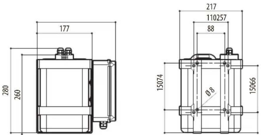
Fig. 47 Water tank 5l (1.3gal), 5m (16ft) delivery.
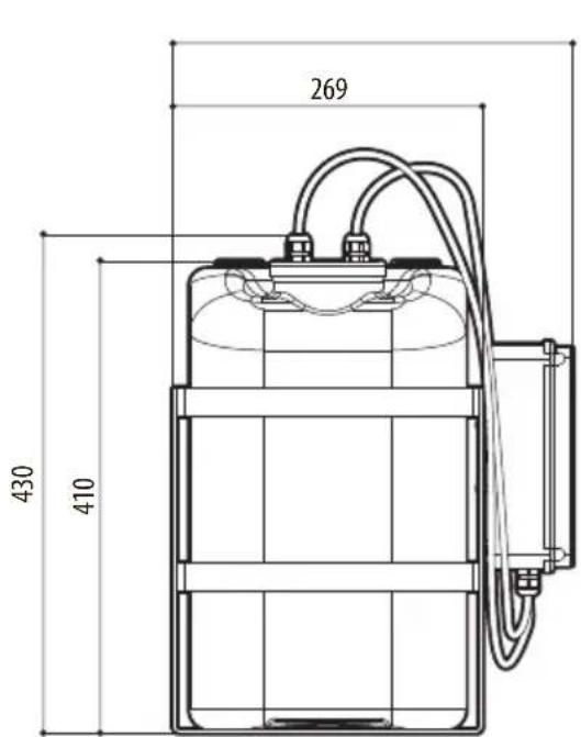
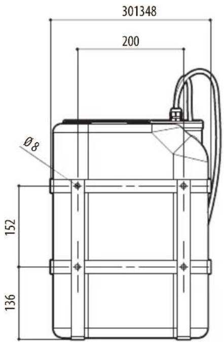
Fig. 48 Water tank 23l (6gal), 5m (16ft) delivery.
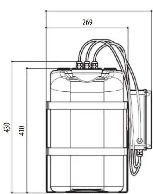
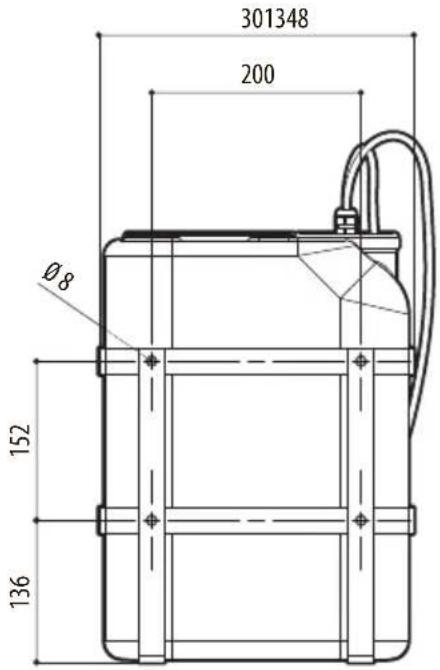
Fig. 49 Water tank 23l (6gal), 11m (36ft) delivery.
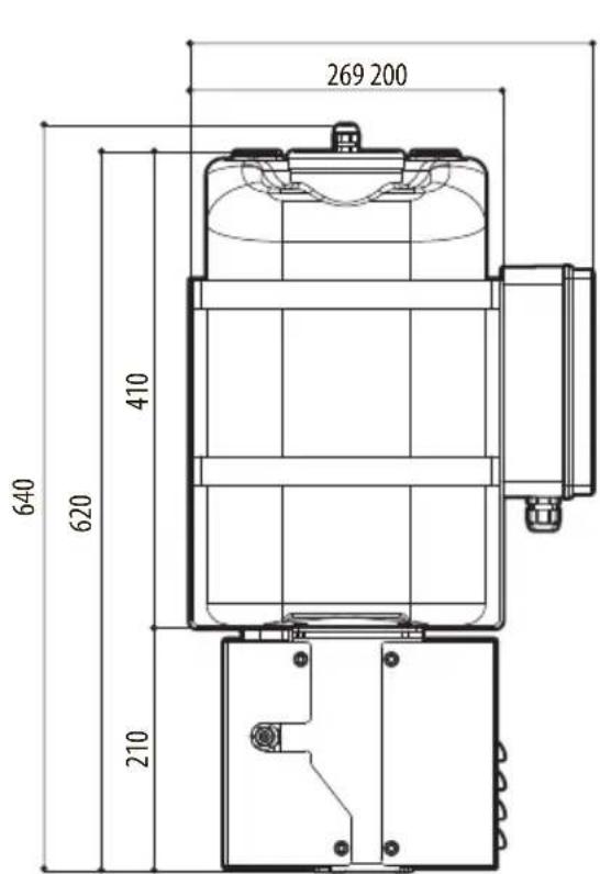
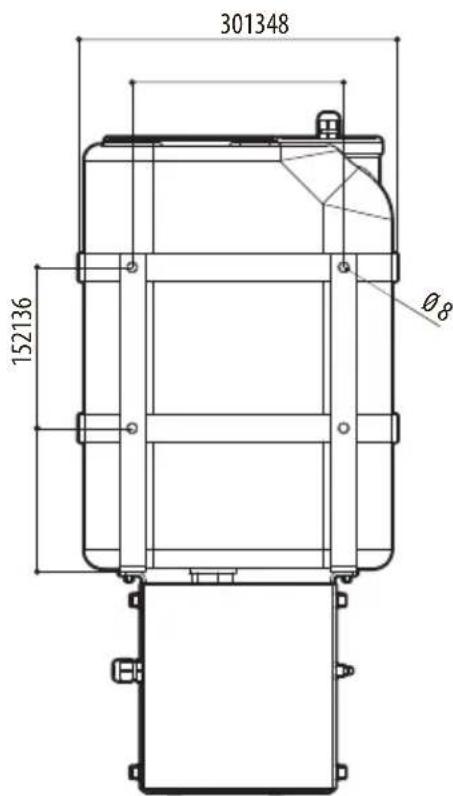
Fig. 50 Water tank 23l (6gal), 30m (98ft) delivery.
WASPT
natural_image
Technical line drawing of a mechanical component with no visible text or symbols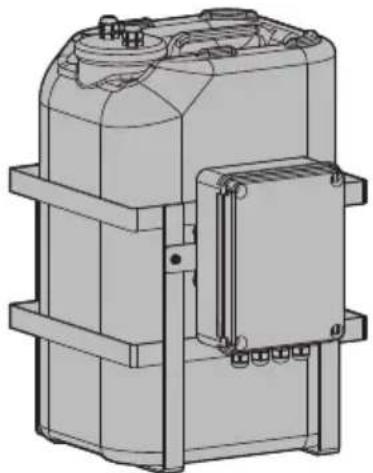
natural_image
Technical line drawing of a mechanical device with no visible text or symbols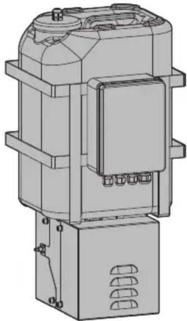
natural_image
Technical line drawing of a mechanical device with no visible text or symbolsSommario
natural_image
Technical diagram showing two mechanical assembly configurations with arrows indicating force or movement (no text or symbols present)Fig. 1
natural_image
Technical line drawing of two mechanical components with no visible text or symbolsFig. 2
Fig. 3 Tanica 5l, prevalenza 5m.
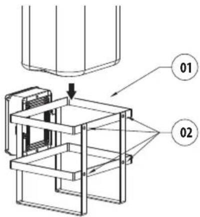
Fig. 4 Tanica 23l, prevalenza 5m o 11m.
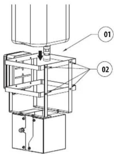
Fig. 5 Tanica 23l, prevalenza 30m.
natural_image
Diagram of a rectangular electronic component with internal connectors and an arrow indicating direction (no text or symbols)Fig. 6
Fig. 10
Fig. 12
Fig. 13
natural_image
Diagram showing two types of pipe fittings: a cylindrical connector and a threaded connector, with no text or symbols present.Fig. 16
natural_image
Diagram of two connected pipe connectors with a directional arrow indicating assembly (no text or symbols)Fig. 17
Fig. 19
natural_image
Technical illustration of a robotic arm joint with a close-up inset showing the mechanism (no text or symbols present)Fig. 20
Fig. 21
natural_image
Technical line drawing of a mechanical assembly with a bolt and nut (no text or symbols)Fig. 23
natural_image
Line drawing of a mechanical component with an arrow indicating direction (no text or symbols)natural_image
Diagram showing two pipe fitting configurations: one with a curved arrow indicating direction, the other with a threaded end (no text or symbols)Fig. 29
natural_image
Technical illustration of two connected pipe connectors with a directional arrow indicating assembly (no text or symbols)Fig. 30
Fig. 32
natural_image
Technical line drawing of a mechanical device with a circular housing and clamping tool (no text or symbols)Fig. 33
Fig. 34
Fig. 36
natural_image
Technical illustration of two pipe fittings with a directional arrow indicating assembly (no text or symbols)Fig. 38
natural_image
Technical illustration of two connected mechanical connectors with a directional arrow indicating assembly (no text or symbols present)Fig. 39
Fig. 41
natural_image
Technical diagram of a mechanical assembly with no visible text or symbolsFig. 42
natural_image
Technical line drawing of a mechanical device with articulated joints and mounting bracket (no text or symbols)natural_image
Technical line drawing of a mechanical device with cylindrical components and wiring (no text or symbols)natural_image
Technical line drawing of a robotic arm mounted on a box, showing wiring and components (no text or symbols)natural_image
Technical diagram of a mechanical assembly with rollers and housing (no text or labels)Fig. 46
natural_image
Technical line drawing of a mechanical component with no visible text or symbols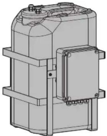
natural_image
Technical line drawing of a mechanical device with no visible text or symbols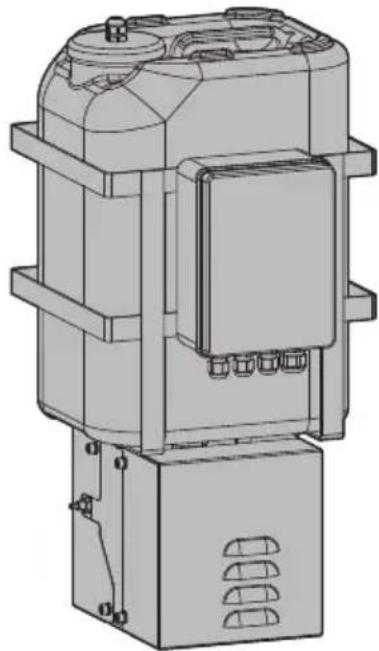
natural_image
Technical line drawing of a mechanical device with no visible text or symbolsSommaire
natural_image
Technical diagram showing two mechanical assembly configurations with arrows indicating force or movement (no text or symbols present)Fig. 1
natural_image
Technical line drawing of two mechanical components with no visible text or symbolsFig. 2
natural_image
Diagram of a rectangular device with internal components and an arrow indicating direction (no text or symbols)Fig. 6
Fig. 10
Fig. 12
Fig. 13
natural_image
Diagram showing two types of pipe fittings: a cylindrical connector and a threaded pipe fitting, with no text or symbols present.Fig. 16
natural_image
Technical illustration of two connected pipe connectors with a directional arrow indicating assembly (no text or symbols)Fig. 17
Fig. 19
natural_image
Technical illustration of a robotic arm joint with a tool inserted, showing no text or symbolsFig. 20
Fig. 21
natural_image
Technical line drawing of a mechanical component with a directional arrow indicating motion (no text or symbols)Fig. 22 Position de lavage finale.
Fig. 23
natural_image
Technical line drawing of a mechanical clamp or bracket assembly (no text or symbols)Fig. 24 Position de lavage finale.
natural_image
Diagram showing two types of pipe fittings: a cylindrical connector and a threaded connector, with no text or symbols present.Fig. 29
natural_image
Technical illustration of two connected mechanical connectors with a directional arrow indicating assembly (no text or symbols present)Fig. 30
Fig. 32
natural_image
Technical line drawing of a mechanical device with a circular housing and clamping tool (no text or symbols)Fig. 33
Fig. 34
Fig. 36
natural_image
Technical illustration of two pipe fittings with a directional arrow indicating assembly (no text or symbols)Fig. 38
natural_image
Technical illustration of two connected mechanical connectors with a directional arrow indicating assembly (no text or symbols present)Fig. 39
Fig. 41
natural_image
Technical line drawing of a mechanical assembly with no visible text or symbolsFig. 42
natural_image
Technical line drawing of a mechanical device with articulated joints and mounting bracket (no text or symbols)natural_image
Technical line drawing of a mechanical device with cylindrical components and wiring (no text or symbols)natural_image
Technical line drawing of a robotic arm mounted on a cabinet, showing wiring and components (no text or symbols)natural_image
Technical diagram of a mechanical assembly with no visible text or symbolsFig. 46
9.1.4 Certifications
9.2.4 Certifications
9.3.4 Certifications
9.3.5 Certifications - Applications marines
9.4.4 Certifications
natural_image
Technical line drawing of a mechanical component with no visible text or symbols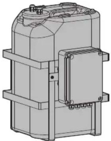
natural_image
Technical line drawing of a mechanical device with no visible text or symbols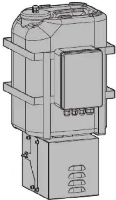
natural_image
Technical line drawing of a mechanical device with no visible text or symbolsInhaltsverzeichnis
1 Allgemeines 5
natural_image
Technical diagram showing two mechanical assembly configurations with arrows indicating force directions (no text or symbols present)Abb. 1
natural_image
Technical line drawing of two mechanical components with no visible text or symbolsAbb. 2
natural_image
Diagram of a rectangular electronic component with a directional arrow indicating compression or force (no text or symbols present)Abb. 6
Abb. 12
natural_image
Diagram showing two types of pipe fittings: a cylindrical connector and a threaded connector, with no text or symbols present.Abb. 16
natural_image
Diagram of two connected pipe connectors with a directional arrow indicating assembly (no text or symbols)Abb. 17
Abb. 19
natural_image
Technical diagram showing a mechanical assembly with an inset view of a bracket and a close-up of a component (no text or symbols present)Abb. 20
Abb. 21
natural_image
Technical line drawing of a mechanical component with a black arrow pointing to a detail (no text or symbols present)Abb. 23
natural_image
Technical line drawing of a mechanical bracket with a bolt and arrow indicating direction (no text or symbols)natural_image
Diagram showing a pipe fitting being inserted into a threaded component (no text or symbols present)Abb. 29
natural_image
Technical illustration of two connected mechanical connectors with a directional arrow indicating assembly (no text or symbols present)Abb. 30
Abb. 32
natural_image
Technical line drawing of a mechanical device with a circular housing and clamping tool (no text or symbols)Abb. 33
Abb. 34
Abb. 36
natural_image
Diagram showing two pipe fittings with a directional arrow indicating movement (no text or symbols present)Abb. 38
natural_image
Technical illustration of two connected mechanical connectors with a directional arrow indicating assembly (no text or symbols present)Abb. 39
Abb. 41
natural_image
Technical diagram of a mechanical assembly with no visible text or symbolsAbb. 42
natural_image
Technical line drawing of a mechanical device with articulated joints and mounting bracket (no text or symbols)natural_image
Technical line drawing of a robotic arm mounted on a box, showing wiring and components (no text or symbols)natural_image
Technical line drawing of a mechanical device with cylindrical components and wiring (no text or symbols)natural_image
Technical diagram of a mechanical assembly with no visible text or symbolsAbb. 46
natural_image
Technical line drawing of a mechanical component with no visible text or symbols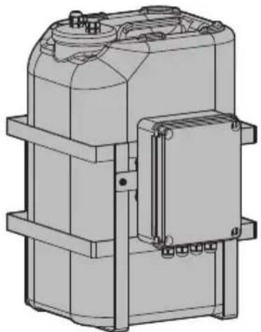
natural_image
Technical line drawing of a mechanical device with mounting brackets and housing (no text or symbols)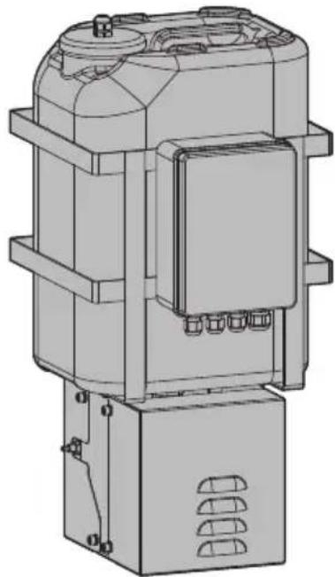
natural_image
Technical line drawing of a mechanical device with no visible text or symbolsnatural_image
Technical diagram showing two mechanical assembly configurations with arrows indicating movement or force directions (no text or symbols present)Рис. 1
natural_image
Technical line drawing of two mechanical components with no visible text or symbolsРис. 2
natural_image
Diagram of a rectangular electronic component with internal connectors and an arrow indicating direction (no text or symbols)Рис. 6
6.4 Описание платы
Рис. 12
natural_image
Diagram showing two types of pipe fittings: a cylindrical connector and a threaded pipe fitting, with no text or symbols present.Рис. 16
natural_image
Technical illustration of two connected pipe connectors with a directional arrow indicating assembly (no text or symbols)Рис. 17
Рис. 19
natural_image
Technical line drawing of a mechanical assembly with an inset showing a component detail (no text or symbols)Рис. 20
Рис. 21
natural_image
Technical line drawing of a mechanical assembly with a bolt and adjustment arrow (no text or symbols)Рис. 23
natural_image
Technical line drawing of a mechanical clamp or bracket with an arrow pointing to a detail (no text or symbols present)natural_image
Diagram showing two mechanical components: a cylindrical connector with a threaded end and an arrow indicating direction (no text or symbols present)Рис. 29
natural_image
Technical illustration of two connected pipe connectors with a directional arrow indicating assembly (no text or symbols present)Рис. 30
Рис. 32
natural_image
Technical line drawing of a mechanical device with a circular housing and clamping mechanism (no text or symbols)Рис. 33
Рис. 34
Рис. 36
natural_image
Diagram showing two types of pipe fittings: a cylindrical connector and a threaded connector, with no text or symbols present.Рис. 38
natural_image
Technical illustration of two connected mechanical connectors with a directional arrow indicating assembly (no text or symbols present)Рис. 39
Рис. 40
Рис. 41
natural_image
Technical line drawing of a mechanical assembly with no visible text or symbolsРис. 42
natural_image
Technical line drawing of a mechanical device with articulated joints and mounting bracket (no text or symbols)natural_image
Technical line drawing of a mechanical device with cylindrical components and wiring (no text or symbols)natural_image
Technical line drawing of a robotic arm mounted on a cabinet, showing wiring and components (no text or symbols)natural_image
Technical diagram of a mechanical assembly with no visible text or symbols
Headquarters Italy VIDEOTEC s.r.l.
Via Friuli, 6 - I-36015 Schio (VI) - Italy
Tel. +39 0445 697411 - Fax +39 0445 697414
Email: info@videotec.com
www.videotec.com
- WASPT
- Contents
- About this manual....5
- Notes on copyright and information on trademarks....5
- Safety rules ....5
- Product description and type designation....6
- Preparing the product for use....6
- Installation....7
- Maintenance 21
- Information on disposal and recycling 21
- Technical data....22
- Technical drawings....24
- About this manual
- Typographical conventions
- DANGER!
- CAUTION!
- INFO
- Notes on copyright and information on trademarks
- Safety rules
- Product description and type designation
- Product marking label
- Preparing the product for use
- Unpacking
- Contents
- Opening of the 30m delivery head pump casing
- Safely disposing of packaging material
- Installation
- Fastening of the metal cage
- Choosing the power supply
- Open the box
- Board description
- Connection of the board
- Installing the fuse
- Pump with 5m (16ft) or 11m (36ft) delivery
- Pump with 30m (98ft) delivery
- Connection of the PTZ camera or stand-alone housing
- Pump manual activation
- Wiper connection
- Wiper manual activation
- Remote control with DTWRX optional board
- Connecting the power supply
- Pump installation
- Adjustment of the level switch position
- Pump with 5m (16ft) delivery
- Pump with 11m (36ft) delivery
- Pump with 30m (98ft) delivery
- Washer installation (ULISSE range)
- Washer installation (ULISSE2)
- Installation examples (6.13 Examples of washer installation, page 20).
- Washer installation (ULISSE COMPACT range)
- Washer installation (ULISSE EVO range)
- Washer installation on the PTZ camera
- Washer installation on the overturned PTZ camera
- Washer installation (NVX range)
- Washer installation (NXPTZ SERIES2 range)
- Examples of washer installation
- Maintenance
- Extraordinary maintenance (to be done only under particular circumstances)
- Fuses replacement
- Replacing the fuse of the pump board
- Tab. 3
- Replacing the fuse on the pump inlet
- Tab. 4
- Information on disposal and recycling
- Technical data
- Washer kit, tank of 5l (1.3gal), pump with 5m (16ft) delivery head
- Mechanical
- Electrical
- Environment
- Certifications
- Washer kit, tank of 23l (6gal), pump with 5m (16ft) delivery head
- Mechanical
- Electrical
- Environment
- Certifications
- Washer kit, tank of 23l (6gal), pump with 11m (36ft) delivery head
- Mechanical
- Electrical
- Environment
- Certifications
- Certifications - Marine applications
- Washer kit, tank of 23l (6gal), pump with 30m (98ft) delivery head
- Mechanical
- Electrical
- Environment
- Certifications
- Technical drawings
- Sommario
- Sommaire
- Certifications - Applications marines
- Inhaltsverzeichnis
- Allgemeines 5
- Abb. 29
- Abb. 30
- Abb. 32
- Abb. 33
- Abb. 34
- Описание платы
- Рис. 32
- Рис. 33
- Рис. 34
Brand : Videotec
Model : WASPT
Category : Water pump