
GP18DB - Sander HiKOKI - Free user manual and instructions
Find the device manual for free GP18DB HiKOKI in PDF.

| Brand | HiKOKI |
| Model | GP18DB |
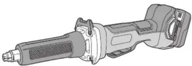
| Product type | Cordless straight grinder (sander) |
| Rated voltage | 18 V (lithium-ion battery) |
| No-load speed | 7000 - 29000 min⁻¹ (electronic variable) |
| Max. disc diameter | 50 mm |
| Clamping chuck capacity | 6 mm (up to 8 mm depending on region) |
| Weight (with battery) | 2.3 kg (BSL1850C) / 2.8 kg (BSL36B18) |
| Power supply | 18 V lithium-ion battery (compatible with BSL18xx and Multi-volt series) |
| Electronic functions | Soft start, overload/overheat protection, electric brake, anti-kickback, restart prevention |
| Speed modes | Transmission mode (5 stages) and Auto mode (noise/vibration reduction) |
| Applications | Internal grinding, finishing of dies, castings, tools |
| Safety equipment | Safety glasses, hearing protection, dust mask recommended |
| Maintenance | Clean terminals, filter, and air vents; inspect discs before use |
| Noise level | Sound pressure 79 dB(A), sound power 90 dB(A) |
| Vibrations | Emission value: 7.7 m/s² (disc <50 mm) / 13.9 m/s² (disc ≥50 mm) |
| Included accessories | Main unit, clamping chuck, wrenches, side handle, filter |
| Warranty | Manufacturer's warranty according to national regulations |
Frequently Asked Questions - GP18DB HiKOKI
User questions about GP18DB HiKOKI
0 question about this device. Answer the ones you know or ask your own.
Ask a new question about this device
Download the instructions for your Sander in PDF format for free! Find your manual GP18DB - HiKOKI and take your electronic device back in hand. On this page are published all the documents necessary for the use of your device. GP18DB by HiKOKI.
USER MANUAL GP18DB HiKOKI
natural_image
Technical line drawing of a mechanical tool assembly (no text or symbols visible)GP18DA GP18DB
natural_image
Technical illustration of a mechanical power tool with meshing and mounting bracket (no text or symbols)
en Handling instructions
de Bedienungsanleitung
fr Mode d'emploi
it Istruzioni per l'uso
nl Gebruiksaanwijzing
es Instrucciones de manejo
pt Instruções de uso
sv Bruksanvisning
da Brugsanvisning
no Bruksanvisning
fi Käyttöohjeet
el Οδηγίες χειρισμού
pl Instrukcja obsługi
hu Kezelési utasítás
cs Návod k obsluze
ro Instructiuni de utilizare
① Navodila za rokovanje
⑥sk Pokyny na manipuláciu
bg Инструкция за експлоатация
sr Uputstvo za rukovanje
hr Upute za rukovanje
1
2
3
4
flowchart
graph TD
    A["Step 1: Initial mechanical part with parts 13, 14"] --> B["Step 2: Rotation of part 5"]
    B --> C["Step 3: Rotation of part 6"]
    C --> D["Step 4: Rotation of part 7"]
    D --> E["End"]
5
6
7


8
9
10
GENERAL POWER TOOL SAFETY WARNINGS

WARNING
Read all safety warnings and all instructions.
Failure to follow the warnings and instructions may result in electric shock, fi re and/or serious injury.
Save all warnings and instructions for future reference.
The term “power tool” in the warnings refers to your mains-operated (corded) power tool or battery-operated (cordless) power tool.
1) Work area safety
a) Keep work area clean and well lit. Cluttered or dark areas invite accidents.
b) Do not operate power tools in explosive atmospheres, such as in the presence of fl ammable liquids, gases or dust. Power tools create sparks which may ignite the dust or fumes.
c) Keep children and bystanders away while operating a power tool. Distractions can cause you to lose control.
2) Electrical safety
a) Power tool plugs must match the outlet. Never modify the plug in any way.
Do not use any adapter plugs with earthed (grounded) power tools.
Unmodified plugs and matching outlets will reduce risk of electric shock.
b) Avoid body contact with earthed or grounded surfaces, such as pipes, radiators, ranges and refrigerators. There is an increased risk of electric shock if your body is earthed or grounded.
c) Do not expose power tools to rain or wet conditions. Water entering a power tool will increase the risk of electric shock.
d) Do not abuse the cord. Never use the cord for carrying, pulling or unplugging the power tool. Keep cord away from heat, oil, sharp edges or moving parts.
Damaged or entangled cords increase the risk of electric shock.
e) When operating a power tool outdoors, use an extension cord suitable for outdoor use. Use of a cord suitable for outdoor use reduces the risk of electric shock.
f) If operating a power tool in a damp location is unavoidable, use a residual current device (RCD) protected supply. Use of an RCD reduces the risk of electric shock.
3) Personal safety
a) Stay alert, watch what you are doing and use common sense when operating a power tool. Do not use a power tool while you are tired or under the influence of drugs, alcohol or medication.
A moment of inattention while operating power tools may result in serious personal injury.
b) Use personal protective equipment. Always wear eye protection.
Protective equipment such as dust mask, non-skid safety shoes, hard hat, or hearing protection used for appropriate conditions will reduce personal injuries.
c) Prevent unintentional starting. Ensure the switch is in the off position before connecting to power source and/or battery pack, picking up or carrying the tool.
Carrying power tools with your fi nger on the switch or energising power tools that have the switch on invites accidents.
d) Remove any adjusting key or wrench before turning the power tool on.
A wrench or a key left attached to a rotating part of the power tool may result in personal injury.
e) Do not overreach. Keep proper footing and balance at all times.
This enables better control of the power tool in unexpected situations.
f) Dress properly. Do not wear loose clothing or jewellery. Keep your hair, clothing and gloves away from moving parts.
Loose clothes, jewellery or long hair can be caught in moving parts.
g) If devices are provided for the connection of dust extraction and collection facilities, ensure these are connected and properly used.
Use of dust collection can reduce dust-related hazards.
4) Power tool use and care
a) Do not force the power tool. Use the correct power tool for your application.
The correct power tool will do the job better and safer at the rate for which it was designed.
b) Do not use the power tool if the switch does not turn it on and off.
Any power tool that cannot be controlled with the switch is dangerous and must be repaired.
c) Disconnect the plug from the power source and/or the battery pack from the power tool before making any adjustments, changing accessories, or storing power tools.
Such preventive safety measures reduce the risk of starting the power tool accidentally.
d) Store idle power tools out of the reach of children and do not allow persons unfamiliar with the power tool or these instructions to operate the power tool.
Power tools are dangerous in the hands of untrained users.
e) Maintain power tools. Check for misalignment or binding of moving parts, breakage of parts and any other condition that may affect the power tool's operation.
If damaged, have the power tool repaired before use.
Many accidents are caused by poorly maintained power tools.
f) Keep cutting tools sharp and clean.
Properly maintained cutting tools with sharp cutting edges are less likely to bind and are easier to control.
g) Use the power tool, accessories and tool bits etc. in accordance with these instructions, taking into account the working conditions and the work to be performed.
Use of the power tool for operations different from those intended could result in a hazardous situation.
5) Battery tool use and care
a) Recharge only with the charger specified by the manufacturer.
A charger that is suitable for one type of battery pack may create a risk of fi re when used with another battery pack.
b) Use power tools only with specifically designated battery packs.
Use of any other battery packs may create a risk of injury and fire.
English
c) When battery pack is not in use, keep it away from other metal objects, like paper clips, coins, keys, nails, screws or other small metal objects, that can make a connection from one terminal to another.
Shorting the battery terminals together may cause burns or a fire.
d) Under abusive conditions, liquid may be ejected from the battery; avoid contact. If contact accidentally occurs, fl ush with water. If liquid contacts eyes, additionally seek medical help.
Liquid ejected from the battery may cause irritation or burns.
6) Service
a) Have your power tool serviced by a qualified repair person using only identical replacement parts.
This will ensure that the safety of the power tool is maintained.
PRECAUTION
Keep children and infi rm persons away.
When not in use, tools should be stored out of reach of children and infi rm persons.
SAFETY WARNINGS COMMON FOR GRINDING OPERATIONS
a) This power tool is intended to function as a grinder. Read all safety warnings, instructions, illustrations and specifications provided with this power tool.
Failure to follow all instructions listed below may result in electric shock, fire and/or serious injury.
b) Operations such as sanding, wire brushing or polishing are not recommended to be performed with this power tool.
Operations for which the power tool was not designed may create a hazard and cause personal injury.
c) Do not use accessories which are not specifically designed and recommended by the tool manufacturer.
Just because the accessory can be attached to your power tool, it does not assure safe operation.
d) The rated speed of the accessory must be at least equal to the maximum speed marked on the power tool.
Accessories running faster than their rated speed can break and fly apart.
e) The outside diameter and the thickness of your accessory must be within the capacity rating of your power tool.
Incorrectly sized accessories cannot be adequately guarded or controlled.
f) The arbour size of wheels, sanding drums or any other accessory must properly fit the spindle or collet of the power tool.
Accessories that do not match the mounting hardware of the power tool will run out of balance, vibrate excessively and may cause loss of control.
g) Mandrel mounted wheels, sanding drums, cutters or other accessories must be fully inserted into the collet or chuck.
If the mandrel is insufficiently held and/or the overhang of the wheel is too long, the mounted wheel may become loose and be ejected at high velocity.
h) Do not use a damaged accessory. Before each use inspect the accessory such as abrasive wheels for chips and cracks, backing pad for cracks, tear or excess wear, wire brush for loose or cracked wires. If power tool or accessory is dropped, inspect for damage or install an undamaged accessory. After inspecting and installing an accessory, position yourself and bystanders away from the plane of the rotating accessory and run the power tool at maximum no-load speed for one minute.
Damaged accessories will normally break apart during this test time.
i) Wear personal protective equipment. Depending on application, use face shield, safety goggles or safety glasses. As appropriate, wear dust mask, hearing protectors, gloves and workshop apron capable of stopping small abrasive or workpiece fragments.
The eye protection must be capable of stopping flying debris generated by various operations. The dust mask or respirator must be capable of filtrating particles generated by your operation. Prolonged exposure to high intensity noise may cause hearing loss.
j) Keep bystanders a safe distance away from work area. Anyone entering the work area must wear personal protective equipment.
Fragments of workpiece or of a broken accessory may fly away and cause injury beyond immediate area of operation.
k) Hold the power tool by insulated gripping surfaces only, when performing an operation where the cutting accessory may contact hidden wiring.
Cutting accessory contacting a "live" wire may make exposed metal parts of the power tool "live" and could give the operator an electric shock.
I) Always hold the tool firmly in your hand(s) during the start-up.
The reaction torque of the motor, as it accelerates to full speed, can cause the tool to twist.
m) Use clamps to support workpiece whenever practical. Never hold a small workpiece in one hand and the tool in the other hand while in use.
Clamping a small workpiece allows you to use your hand(s) to control the tool. Round material such as dowel rods, pipes or tubing have a tendency to roll while being cut, and may cause the bit to bind or jump toward you.
n) Never lay the power tool down until the accessory has come to a complete stop.
The spinning accessory may grab the surface and pull the power tool out of your control.
o) After changing the bits or making any adjustments, make sure the collet nut, chuck or any other adjustment devices are securely tightened.
Loose adjustment devices can unexpectedly shift, causing loss of control, loose rotating components will be violently thrown.
p) Do not run the power tool while carrying it at your side.
Accidental contact with the spinning accessory could snag your clothing, pulling the accessory into your body.
q) Regularly clean the power tool's air vents.
The motor's fan will draw the dust inside the housing and excessive accumulation of powdered metal may cause electrical hazards.
r) Do not operate the power tool near flammable materials.
Sparks could ignite these materials.
s) Do not use accessories that require liquid coolants.
Using water or other liquid coolants may result in electrocution or shock.
KICKBACK AND RELATED WARNINGS
Kickback is a sudden reaction to a pinched or snagged rotating wheel, backing pad, brush or any other accessory. Pinching or snagging causes rapid stalling of the rotating accessory which in turn causes the uncontrolled power tool to be forced in the direction opposite of the accessory's rotation at the point of the binding.
For example, if an abrasive wheel is snagged or pinched by the workpiece, the edge of the wheel that is entering into the pinch point can dig into the surface of the material causing the wheel to climb out or kick out. The wheel may either jump toward or away from the operator, depending on direction of the wheel's movement at the point of pinching.
Abrasive wheels may also break under these conditions.
Kickback is the result of power tool misuse and/or incorrect operating procedures or conditions and can be avoided by taking proper precautions as given below.
a) Maintain a firm grip on the power tool and position your body and arm to allow you to resist kickback forces.
The operator can control kickback forces, if proper precautions are taken.
b) Use special care when working corners, sharp edges etc. Avoid bouncing and snagging the accessory.
Corners, sharp edges or bouncing have a tendency to snag the rotating accessory and cause loss of control or kickback.
c) Do not attach a toothed saw blade.
Such blades create frequent kickback and loss of control.
d) Always feed the bit into the material in the same direction as the cutting edge is exiting from the material (which is the same direction as the chips are thrown).
Feeding the tool in the wrong direction causes the cutting edge of the bit to climb out of the work and pull the tool in the direction of this feed.
e) When using rotary files, cut-off wheels, high-speed cutters or tungsten carbide cutters, always have the work securely clamped.
These wheels will grab if they become slightly canted in the groove, and can kickback. When a cut-off wheel grabs, the wheel itself usually breaks. When a rotary file, high-speed cutter or tungsten carbide cutter grabs, it may jump from the groove and you could lose control of the tool.
SAFETY WARNINGS SPECIFIC FOR GRINDING AND ABRASIVE CUTTING-OFF OPERATIONS
a) Use only wheel types that are recommended for your power tool and only for recommended applications. For example: do not grind with the side of a cut-off wheel.
Abrasive cut-off wheels are intended for peripheral grinding, side forces applied to these wheels may cause them to shatter.
b) For threaded abrasive cones and plugs use only undamaged wheel mandrels with an unrelieved shoulder flange that are of correct size and length.
Proper mandrels will reduce the possibility of breakage.
c) Do not "jam" a cut-off wheel or apply excessive pressure. Do not attempt to make an excessive depth of cut.
Overstressing the wheel increases the loading and susceptibility to twisting or snagging of the wheel in the cut and the possibility of kickback or wheel breakage.
d) Do not position your hand in line with and behind the rotating wheel.
When the wheel, at the point of operation, is moving away from your hand, the possible kickback may propel the spinning wheel and the power tool directly at you.
e) When wheel is pinched, snagged or when interrupting a cut for any reason, switch off the power tool and hold the power tool motionless until the wheel comes to a complete stop. Never attempt to remove the cut-off wheel from the cut while the wheel is in motion otherwise kickback may occur. Investigate and take corrective action to eliminate the cause of wheel pinching or snagging.
f) Do not restart the cutting operation in the workpiece. Let the wheel reach full speed and carefully re-enter the cut.
The wheel may bind, walk up or kickback if the power tool is restarted in the workpiece.
g) Support panels or any oversized workpiece to minimize the risk of wheel pinching and kickback.
Large workpieces tend to sag under their own weight. Supports must be placed under the workpiece near the line of cut and near the edge of the workpiece on both sides of the wheel.
h) Use extra caution when making a "pocket cut" into existing walls or other blind areas.
The protruding wheel may cut gas or water pipes, electrical wiring or objects that can cause kickback.
GENERAL SAFETY INSTRUCTIONS FOR CORDLESS GRINDER
- Check that speed marked on the wheel is equal to or greater than the rated speed of the grinder;
- Ensure that the wheel dimensions are compatible with the grinder;
- Abrasive wheels shall be stored and handled with care in accordance with manufacturer's instructions;
- Inspect the grinding wheel before use, do not use chipped, cracked or otherwise defective products;
- Ensure that mounted wheels and points are fitted in accordance with the manufacturer's instructions;
- Ensure that blotters are used when they are provided with the bonded abrasive product and when they are required;
- Ensure that the abrasive product is correctly mounted and tightened before use and run the tool at no-load for 30 seconds in a safe position, stop immediately if there is considerable vibration or if other defects are detected. If this condition occurs, check the machine to determine the cause;
- If a guard is equipped with the tool never use the tool without such a guard;
- Do not use separate reducing bushings or adapters to adapt large hole abrasive wheels;
- For tools intended to be fitted with threaded hole wheel, ensure that the thread in the wheel is long enough to accept the spindle length;
– Check that the work piece is properly supported;
- Do not use cutting off wheel for side grinding;
- Ensure that sparks resulting from use do not create a hazard e.g. do not hit persons, or ignite flammable substances;
English
- Ensure that ventilation openings are kept clear when working in dusty conditions, if it should become necessary to clear dust, fi rst disconnect the tool from the mains supply (use non metallic objects) and avoid damaging internal parts;
- Always use eye and ear protection. Other personal protective equipment such as dust mask, gloves, helmet and apron should be worn;
- Pay attention to the wheel that continues to rotate after the tool is switched off.
- Do not allow foreign matter to enter the hole for connecting the rechargeable battery.
- Never disassemble the rechargeable battery and charger.
- Never short-circuit the rechargeable battery. Shortcircuting the battery will cause a great electric current and overheat. It results in burn or damage to the battery.
- Do not dispose of the battery in fire. If the battery is burnt, it may explode.
- Do not insert object into the air ventilation slots of the charger. Inserting metal objects or inflammables into the charger air ventilation slots will result in electrical shock hazard or damaged charger.
- Bring the battery to the shop from which it was purchased as soon as the post-charging battery life becomes too short for practical use. Do not dispose of the exhausted battery.
ADDITIONAL SAFETY WARNINGS
- Ensure that the wheel to be utilized is the correct type and free of cracks or surface defects. Also ensure that the wheel is properly mounted and the collet chuck is securely tightened.
- To prolong the life of the machine and ensure a first class fi nish, it is important that the machine should not be overloaded by applying too much pressure. In most applications, the weight of the machine alone is suffi cient for eff ective grinding. Too much pressure will result in reduced rotational speed, inferior surface finish, and overloading which could reduce the life of the machine.
- The wheel continues to rotate after the tool is switched off.
After switching off the machine, do not put it down until the wheel has come to a complete stop. Apart from avoiding serious accidents, this precaution will reduce the amount of dust and swarf sucked into the machine.
- Be careful of brake kickback.
This cordless die grinder features an electric brake that functions when the switch is released. As there is some kickback when the brake functions, be sure to hold the main body securely. - Do not use the product if the tool or the battery terminals (battery mount) are deformed. Installing the battery could cause a short circuit that could result in smoke emission or ignition.
- Keep the tool's terminals (battery mount) free of swarf and dust.
- Prior to use, make sure that swarf and dust have not collected in the area of the terminals.
During use, try to avoid swarf or dust on the tool from falling on the battery.
When suspending operation or after use, do not leave the tool in an area where it may be exposed to falling swarf or dust.
Doing so could cause a short circuit that could result in smoke emission or ignition.
PRECAUTIONS FOR BATTERY AND CHARGER
- Always charge the battery at an ambient temperature of -10-40^ . A temperature of less than -10^ will result in over charging which is dangerous. The battery cannot be charged at a temperature greater than 40^ . The most suitable temperature for charging is that of 20-25^ .
- Do not use the charger continuously.
When one charging is completed, leave the charger for about 15 minutes before the next charging of battery.
- Do not allow foreign matter to enter the hole for connecting the rechargeable battery.
- Never disassemble the rechargeable battery or charger.
- Never short-circuit the rechargeable battery.
Short-circuiting the battery will cause a great electric current and overheat. It results in burn or damage to the battery.
- Do not dispose of the battery in fire.
If the battery is burnt, it may explode.
- Using an exhausted battery will damage the charger.
- Bring the battery to the shop from which it was purchased as soon as the post-charging battery life becomes too short for practical use. Do not dispose of the exhausted battery.
- Do not insert objects into the air ventilation slots of the charger.
Inserting metal objects or flammable into the charger air ventilation slots will result in an electrical shock hazard or damage to the charger.
CAUTION ON LITHIUM-ION BATTERY
To extend the lifetime, the lithium-ion battery equips with the protection function to stop the output.
In the cases of 1 to 3 described below, when using this product, even if you are pulling the switch, the motor may stop. This is not the trouble but the result of protection function.
- When the battery power remaining runs out, the motor stops. In such a case, charge it up immediately.
- If the tool is overloaded, the motor may stop. In this case, release the switch of tool and eliminate causes of overloading. After that, you can use it again.
- If the battery is overheated under overload work, the battery power may stop. In this case, stop using the battery and let the battery cool. After that, you can use it again.
Furthermore, please heed the following warning and caution. WARNING
In order to prevent any battery leakage, heat generation, smoke emission, explosion and ignition beforehand, please be sure to heed the following precautions.
- Make sure that swarf and dust do not collect on the battery.
○ During work make sure that swarf and dust do not fall on the battery.
○ Make sure that any swarf and dust falling on the power tool during work do not collect on the battery. - Do not store an unused battery in a location exposed to swarf and dust.
Before storing a battery, remove any swarf and dust that may adhere to it and do not store it together with metal parts (screws, nails, etc.). - Do not pierce battery with a sharp object such as a nail, strike with a hammer, step on, throw or subject the battery to severe physical shock.
- Do not use an apparently damaged or deformed battery.
-
Do not use the battery in reverse polarity.
-
Do not connect directly to an electrical outlets or car cigarette lighter sockets.
- Do not use the battery for a purpose other than those specified.
- If the battery charging fails to complete even when a specified recharging time has elapsed, immediately stop further recharging.
- Do not put or subject the battery to high temperatures or high pressure such as into a microwave oven, dryer, or high pressure container.
- Keep away from fi re immediately when leakage or foul odor are detected.
- Do not use in a location where strong static electricity generates.
- If there is battery leakage, foul odor, heat generated, discolored or deformed, or in any way appears abnormal during use, recharging or storage, immediately remove it from the equipment or battery charger, and stop use.
- Do not immerse the battery or allow any fluids to flow inside. Conductive liquid ingress, such as water, can cause damage resulting in fire or explosion. Store your battery in a cool, dry place, away from combustible and fl ammable items. Corrosive gas atmospheres must be avoided.
CAUTION
- If liquid leaking from the battery gets into your eyes, do not rub your eyes and wash them well with fresh clean water such as tap water and contact a doctor immediately.
If left untreated, the liquid may cause eye-problems.
- If liquid leaks onto your skin or clothes, wash well with clean water such as tap water immediately.
There is a possibility that this can cause skin irritation.
- If you find rust, foul odor, overheating, discolor, deformation, and/or other irregularities when using the battery for the first time, do not use and return it to your supplier or vendor.
WARNING
If a conductive foreign matter enters in the terminal of lithium ion battery, the battery may be shorted, causing fire. When storing the lithium ion battery, obey surely the rules of following contents.
○ Do not place conductive debris, nail and wires such as iron wire and copper wire in the storage case.
To prevent shorting from occurring, load the battery in the tool or insert securely the battery cover for storing until the ventilator is not seen.
REGARDING LITHIUM-ION BATTERY TRANSPORTATION
When transporting a lithium-ion battery, please observe the following precautions.
WARNING
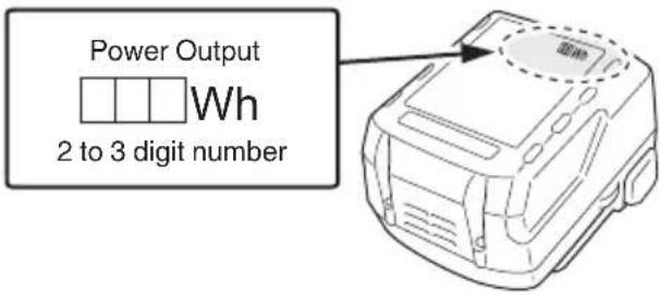
Notify the transporting company that a package contains a lithium-ion battery, inform the company of its power output and follow the instructions of the transportation company when arranging transport.
☐ Lithium-ion batteries that exceed a power output of 100 Wh are considered to be in the freight classification of Dangerous Goods and will require special application procedures.
☐ For transportation abroad, you must comply with international law and the rules and regulations of the destination country.
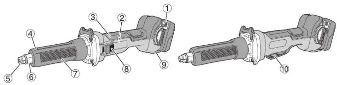
NAMES OF PARTS (Fig. 1–Fig. 10)
| 1 | Battery Latch | 11 | |
| 2 | Motor Pilot lamp | 12 | |
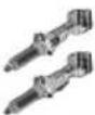
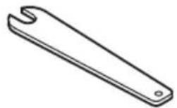
| 3 | Nameplate Wrench (small) | 13 | |
| 4 | Nose bracket Wrench (large) | 14 | |
| 5 | Collet chuck | 15 | Wheel |
| 6 | Spindle | 16 | Tapared portion |
| 7 | Front cover | 17 | Interior protrusions(2 locations) |
| 8 | Switch knob | 18 | Side handle |
| 9 | Dial | 19 | Off -lock lever |
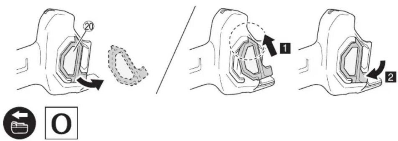
| 10 | Switch lever | 20 | Filter |
SYMBOLS
WARNING
The following show symbols used for the machine. Be sure that you understand their meaning before use.
 | GP18DA / GP18DB: Cordless Die Grinder |
 | To reduce the risk of injury, user must read instruction manual. |
 | Always wear eye protection. |
 | Only for EU countriesDo not dispose of electric tools together with household waste material!In observance of European Directive 2012/19/EU on waste electrical and electronic equipment and its implementation in accordance with national law, electric tools that have reached the end of their life must be collected separately and returned to an environmentally compatible recycling facility. |
| --- | Direct current |
| V | Rated voltage |
| n_0 | No-load speed |
| n | Rated speed |
| min-1 | Revolution or reciprocations per minuteDisconnect the battery |
 | Switching ON |
 | Switching OFF |
 | Warning |
STANDARD ACCESSORIES
In addition to the main unit (1 unit), the package contains the accessories listed on page 231.
Standard accessories are subject to change without notice.
APPLICATIONS
○ Finishing of dies for press working, die casting and moulding.
○ Finishing of thread cutting dies, tools and other small parts.
- Internal grinding of tools and machine parts.
SPECIFICATIONS
| Model GP18DA GP18DB | ||
| Voltage 18 V | ||
| Rated speed 7000–29000 min | -1 | |
| Max. Wheel diameter 50 mm | ||
| Collet chuck Capacity* 6 mm | ||
| Weight** | 2.3 kg (BSL1850C)2.8 kg (BSL36B18) | |
* This varies depending on the area.
** According to EPTA-Procedure 01/2014
NOTE
Due to HiKOKI's continuing program of research and development, the specifications herein are subject to change without prior notice.
Electronic control
○ Soft start
Reduces recoil against the operator by managing the number of rotations during startup.
○ Overload protection
This protection feature cuts off the power to the motor in the event of overloading of motor or a conspicuous reduction in rotational speed during operation.
When the overload protection feature has been activated, the motor may stop.
In this case, release the tool switch and eliminate causes of overloading.
After that you can use it again.
○ Overheat protection
This protection feature cuts off the power to the motor and stops the power tool in the event of overheating of motor during operation.
When the overheat protection feature has been activated, the motor may stop.
In this case, release the tool switch and cool it down in a few minutes.
After that you can use it again.
○ Restart prevention function
When the power is still switched on, the tool will not restart when a battery is installed. This function can be canceled once the tool is switched off.
○ Braking Function
Brake is activated when the switch is turned off, stopping the motor's rotation.
○ Kickback Protection
The kickback protection feature cuts off the power to the motor and stops the power tool in the event of a sudden drop in the rotational speed of the wheel during operation (for example, if the wheel locks during cutting operation, etc.).
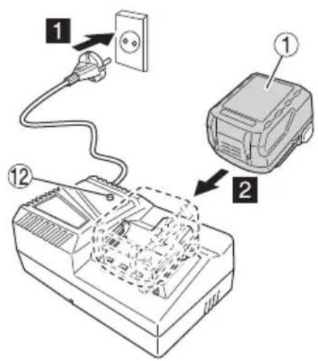
CHARGING
Before using the power tool, charge the battery as follows.
- Connect the charger's power cord to the receptacle. When connecting the plug of the charger to a receptacle, the pilot lamp will blink in red (At 1-second intervals).
- Insert the battery into the charger.
Firmly insert the battery into the charger as shown in Fig. 3 (on page 2).
- Charging
When inserting a battery in the charger, charging will commence and the pilot lamp will light continuously in red.
When the battery becomes fully recharged, the pilot lamp will blink in red. (At 1-second intervals) (See Table 1)
● Pilot lamp indication
The indications of the pilot lamp will be as shown in Table 1, according to the condition of the charger or the rechargeable battery.
Table 1
| Indications of the pilot lamp | ||||
| Pilot lamp(red) | Before charging | Blinks | Lights for 0.5 seconds. Does not light for 0.5 seconds. (off for 0.5 seconds) | |
| While charging Lights | Lights continuously | |||
| Charging complete | Blinks | Lights for 0.5 seconds. Does not light for 0.5 seconds. (off for 0.5 seconds) | ||
| Charging impossible | Flickers | Lights for 0.1 seconds. Does not light for 0.1 seconds. (off for 0.1 seconds) | Malfunction in the battery or the charger | |
| Overheat standby | Blinks | Lights for 1 second. Does not light for 0.5 seconds. (off for 0.5 seconds) | Battery overheated. Unable to charge. (Charging will commence when battery cools) | |
● Regarding the temperatures and charging time of the battery.
The temperatures and charging time will become as shown in Table 2.
Table 2
| Charger | UC18YFSL | ||||||
| Battery | Type of battery Li-ion | ||||||
| Temperatures at which the battery can be recharged | 0°C-50°C | ||||||
| Charging voltage V | 14.4 18 | ||||||
| Charging time, approx. (At 20°C) | BSL14xx series BSL18xx series | Multi volt series | |||||
| (4 cells) (8 cells) (5 cells) (10 cells) (10 cells) | |||||||
| min | BSL1415S:20BSL1415 :22BSL1415X:22BSL1420 :30BSL1425 :35BSL1430C:45 | BSL1430 :45BSL1440 :60BSL1450 :75BSL1460 :90 | BSL1815S:20BSL1815 :22BSL1815X:22BSL1820 :30BSL1825 :35BSL1830C:45BSL1850C:75 | BSL1830 :45BSL1840 :60BSL1850 :75BSL1860 :90 | |||
NOTE
The recharging time may vary according to the ambient temperature and power source voltage.
CAUTION
When the battery charger has been continuously used, the battery charger will be heated, thus constituting the cause of the failures. Once the charging has been completed, give 15 minutes rest until the next charging.
4. Disconnect the charger's power cord from the receptacle.
5. Hold the charger firmly and pull out the battery. NOTE
Be sure to pull out the battery from the charger after use, and then keep it.
Regarding electric discharge in case of new batteries, etc.
As the internal chemical substance of new batteries and batteries that have not been used for an extended period is not activated, the electric discharge might be low when using them the first and second time. This is a temporary phenomenon, and normal time required for recharging will be restored by recharging the batteries 2–3 times.
How to make the batteries perform longer.
(1) Recharge the batteries before they become completely exhausted.
When you feel that the power of the tool becomes weaker, stop using the tool and recharge its battery. If you continue to use the tool and exhaust the electric current, the battery may be damaged and its life will become shorter.
(2) Avoid recharging at high temperatures.
A rechargeable battery will be hot immediately after use. If such a battery is recharged immediately after use, its internal chemical substance will deteriorate, and the battery life will be shortened. Leave the battery and recharge it after it has cooled for a while.
CAUTION
If the battery is charged while it is heated because it has been left for a long time in a location subject to direct sunlight or because the battery has just been used, the pilot lamp of the charger lights up green or lights for 1 second, does not light for 0.5 seconds (off for 0.5 seconds). In such a case, first let the battery cool, then start charging.
English
When the pilot lamp flickers in red (at 0.2-seconds intervals), check for and take out any foreign objects in the charger's battery connector. If there are no foreign objects, it is probable that the battery or charger is malfunctioning. Take it to your authorized Service Center.
○ Since the built-in micro computer takes about 3 seconds to confi rm that the battery being charged with chargers are taken out, wait for a minimum of 3 seconds before reinserting it to continue charging. If the battery is reinserted within 3 seconds, the battery may not be properly charged.
MOUNTING AND OPERATION
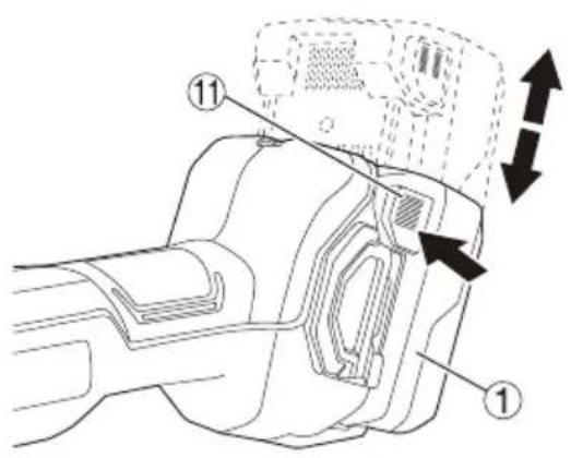
| Action Figure Page | ||
| Removing and inserting the battery 2 | 2 | |
| Charging 3 2 | ||
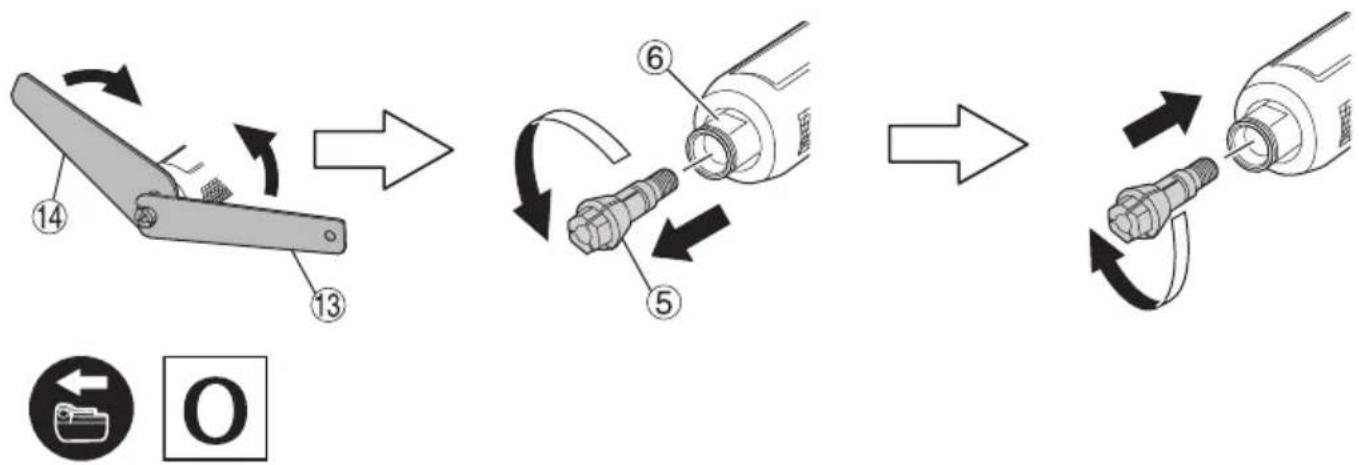
| Removal of a collet chuck 4 2 | ||
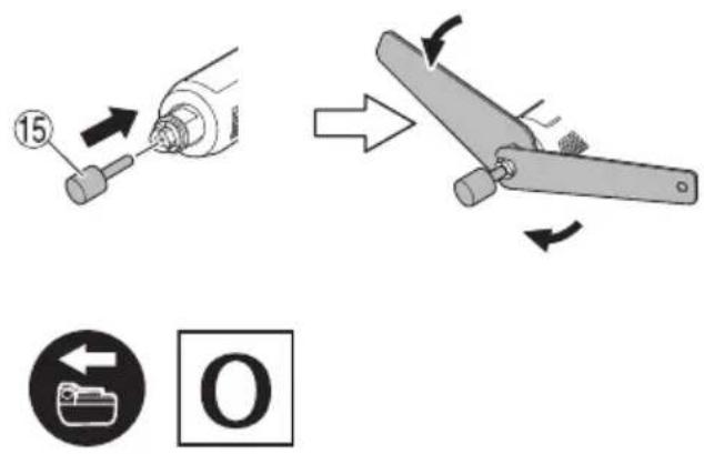
| Installing a wheel*1 | 5 | 3 |
| The attachment position of a wheel 6 | 3 | |
| Using the side handle*2 | 7 | 3 |
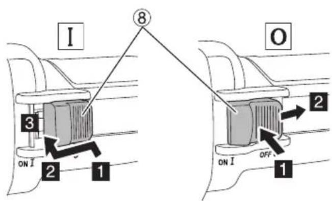
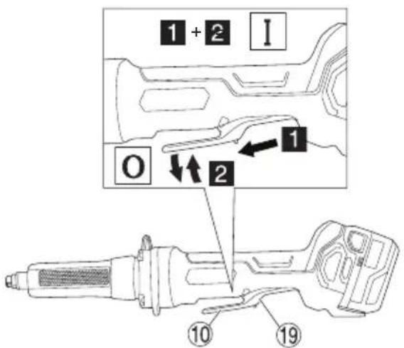
| Switch operation 8 3 | ||
| Dial of variable speed operation*3 | 9 | 4 |
| Selecting accessories — 232, 233 |
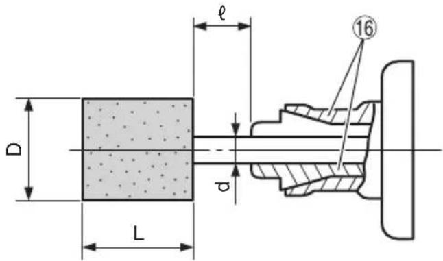
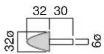
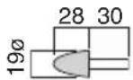
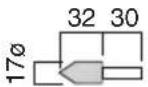
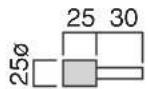
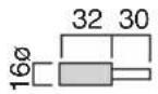
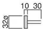
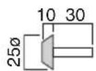
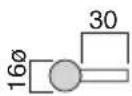
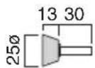
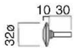
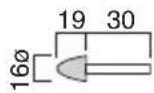
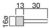
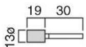
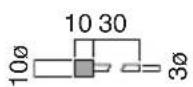
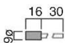
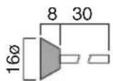
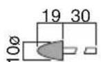
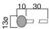
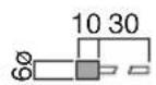
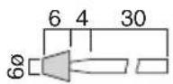
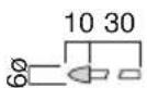
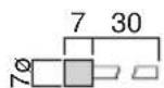
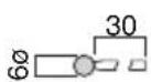
\*1 Installing a wheel (Fig. 5)
Install the wheel so that length is less than 15 mm. If is longer, abnormal vibration will occur, and the machine is not only negatively affected, but there is a possibility of a serious accident.
Make the as small as possible.
When d = 6 mm, 1/4", 8 mm, D of the wheel should be less than the Max. wheel diameter (50 mm). If a wheel with D more than the Max. wheel diameter (50 mm) is used, the circumference speed exceeds the safety limit and the wheel will break. Never use such a wheel.
Distance L varies for D. Determine L referring to the Table 3.
When d = 3 mm, 1/8", D should be less than 10 mm. Determine L referring to the Table 3.
Wheels can be simply attached and detached by using the two wrenches. (Fig. 6)
NOTE
Do not tighten the collet chuck by inserting a shaft thinner than the regular shaft diameter (6 mm) in the chuck or in an empty condition. This practice will damage the collet chuck.
When using a shaft (3 mm), switch to a collet chuck for 3 mm shaft (sold separately). (Fig. 4)
When installing a wheel with shaft, tighten the collet chuck after applying a small quantity of spindle oil (or sewing machine oil) to the tapered portion. (Fig. 5)
Table 3 (when = 15mm )
| d | D | L |
| 3 mm, 3.175 mm (1/8") | 5 mm | 10 mm |
| 6 mm | 13 mm | |
| 8 mm | 16 mm | |
| 10 mm | 13 mm | |
| 6 mm, 6.35 mm (1/4") | 13 mm | 40 mm |
| 16 mm | 40 mm | |
| 20 mm | 25 mm | |
| 25 mm | 25 mm | |
| 32 mm | 13 mm | |
| 38 mm | 7 mm | |
| 8 mm | 25 mm | 32 mm |
| 32 mm | 25 mm | |
| 38 mm | 19 mm |
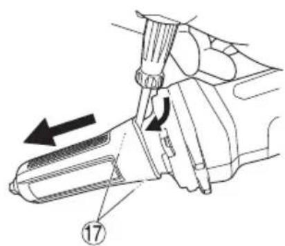
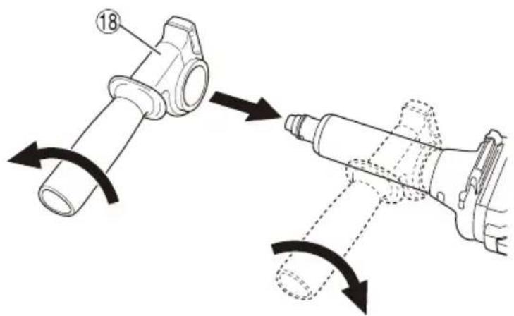
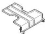
\*2 Using the side handle
Install the side handle after removing the front cover.
Detach the front cover by removing the protrusion on the interior from the hollow in the main unit and pull to remove. If the protrusion is difficult to detach, use a flat-head screwdriver or similar tool.
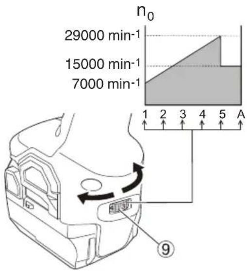
\*3 Dial of variable speed operation
The unit has "Transmission mode" and "Auto mode".
With Transmission mode, the grinder's number of revolutions can be set at one of five stages.
When operating in Transmission mode, the set number of revolutions will be maintained regardless of changes in load.
With Auto mode, you can lower noise and vibration by lowering the maximum number of revolutions while in a no-load state.
While in Auto mode, the number of revolutions will be raised if the load becomes greater during operation.
On the other hand, the number of revolutions will be lowered if the load decreases during operation. (Table 4)
O Set the mode and dial according to work application.
Table 4
| Mode | Status | Number of Revolutions (min-1) | Use | |
| Transmission | Dial Settings | 1 | 7000 | Polishing/finishing |
| 2 | 13800 | Paint removal | ||
| 3 | 16600 | Rust removal | ||
| 4 | 24400 | Burr removal | ||
| 5 | 29000 | Grinding | ||
| Auto | A | 15000 | Work on standby | |
| 29000 | Grinding | |||
Caution when using near welding equipment
When using the grinder in the immediate vicinity of welding equipment, the rotational speed may become unstable. Do not use the grinder near welding equipment.
Precautions on operation
(1) Lightly press the wheel to the material to be ground. When grinding materials, high-speed revolution is necessary. Use a die grinder with high-speed revolution, minimizing the pressing force.
CAUTION
When using the tool at any value except the full speed (Dial scale 5), the motor cannot be sufficiently cooled due to the decreased number of revolution. This could result in the risk of burning and damaging the motor before an overload protective mechanism starts to function.
Make sure that you use the tool by lightly applying it to the surface of material when you use it at any value except the full speed (Dial scale 5).
(2) Dressing the wheel
After attaching a wheel, correct deflection of the wheel center by using a dresser. If the wheel center is eccentric, not only precise fi nishing cannot be achieved but also grinder vibration increases, lowering grinder accuracy and durability.
A clogged or worn wheel will spoil the finishing surface or lower grinding efficiency. Occasionally dress the wheel by applying the dresser.
WHEEL SELECTING METHOD
Types of wheels are varied according to the materials to be ground. Select a wheel appropriate for the material to be ground. The following table is an outline of wheels and materials to be ground.
| Materials to be ground Grain | Grading Bonding | degree Structure Bonding agent | |||
| Mild steel, hard steel, forged steel | WA 60–80 | P | m | V | |
| Cast iron | C | 36 | M-O | m | V |
| Brass, bronze, aluminium | C | 36 | J-K | m | V |
| Ceramic | WA | 60–80 | M | m | V |
| Synthetic resin | C | 36 | K-M | m | V |
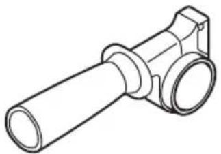
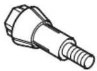
Small-scaled wheels with shaft are prepared for grinding small surfaces. Their dimensions and shapes are shown in "Selecting accessories".
Since wheel shaft diameter is 3 mm, use the collet chuck for 3 mm shaft sold separately by your HiKOKI dealer as an optional accessory.
MAINTENANCE AND INSPECTION
WARNING
Be sure to turned off the switch and remove the battery before maintenance and inspection.
1. Inspecting the wheel
Ensure that the wheel is free of cracks and surface defects.
2. Inspecting the mounting screws
Regularly inspect all mounting screws and ensure that they are properly tightened. Should any of the screws be loose, retighten them immediately. Failure to do so could result in serious hazard.
3. Maintenance of the motor
The motor unit winding is the very “heart” of the power tool. Exercise due care to ensure the winding does not become damaged and/or wet with oil or water.
4. Inspection of terminals (tool and battery)
Check to make sure that swarf and dust have not collected on the terminals.
On occasion check prior, during and after operation.
CAUTION
Remove any swarf or dust which may have collected on the terminals.
Failure to do so may result in malfunction.
5. Cleaning on the outside
When the power tool is stained, wipe with a soft dry cloth or a cloth moistened with soapy water. Do not use chloric solvents, gasoline or paint thinner, for they melt plastics.
6. Cleaning the filter
After use, detach the filter and remove any grime or dust from the screen with an airgun or other tool. (Fig. 10)
NOTE
To clear the unit of grime or dust, periodically run the motor in a no-load state and blow dry air into the ventilation hole with the filter removed.
Accumulation of grime or dust accumulates in the motor can cause damage.
○ After cleaning, make sure to securely attach the filter.
7. Storage
Store the power tool in a place in which the temperature is less than 40^ C and out of reach of children.
NOTE
Storing lithium-ion batteries.
Make sure the lithium-ion batteries have been fully charged before storing them.
Prolonged storage (3 months or more) of batteries with a low charge may result in performance deterioration, significantly reducing battery usage time or rendering the batteries incapable of holding a charge.
However, significantly reduced battery usage time may be recovered by repeatedly charging and using the batteries two to five times.
If the battery usage time is extremely short despite repeated charging and use, consider the batteries dead and purchase new batteries.
English
CAUTION
In the operation and maintenance of power tools, the safety regulations and standards prescribed in each country must be observed.
SELECTING ACCESSORIES
The accessories of this machine are listed on pages 232 and 233.
For details regarding each bit type, please contact the HiKOKI Authorized Service Center.
Important notice on the batteries for the HiKOKI cordless power tools
Please always use one of our designated genuine batteries. We cannot guarantee the safety and performance of our cordless power tool when used with batteries other than these designated by us, or when the battery is disassembled and modified (such as disassembly and replacement of cells or other internal parts).
GUARANTEE
We guarantee HiKOKI Power Tools in accordance with statutory/country specific regulation. This guarantee does not cover defects or damage due to misuse, abuse, or normal wear and tear. In case of complaint, please send the Power Tool, undismantled, with the GUARANTEE CERTIFICATE found at the end of this Handling instruction, to a HiKOKI Authorized Service Center.
Information concerning airborne noise and vibration
The measured values were determined according to EN60745 and declared in accordance with ISO 4871.
Measured A-weighted sound power level: 90 dB (A).
Measured A-weighted sound pressure level: 79 dB (A).
Uncertainty K: 3 dB (A).
Wear hearing protection.
Vibration total values (triax vector sum) determined according to EN60745.
Vibration emission value a_h
depending on the diameter of the artificial wheel
| ≥25 mm and < 50 mm 7.7 | m/s | 2 |
| ≥50 mm 13.9 m/s | 2 |
Uncertainty K = 1.5 m/s ^4
The declared vibration total value has been measured in accordance with a standard test method and may be used for comparing one tool with another.
It may also be used in a preliminary assessment of exposure.
WARNING
☐ The vibration emission during actual use of the power tool can differ from the declared total value depending in the ways in which the tool is used.
- Identify safety measures to protect the operator that are based on an estimation of exposure in the actual conditions of use (taking account of all parts of the operating cycle such as the times when the tool is switched off and when it is running idle in addition to the trigger time).
NOTE
Due to HiKOKI's continuing program of research and development, the specifications herein are subject to change without prior notice.
NAMEN VAN ONDERDELEN (Afb. 1–Afb. 10)
Tabela 3 (onder ℓ = 15 mm)
| d | D | L |
| 3 mm, 3,175 mm (1/8") | 5 mm 10 mm | |
| 6 mm 13 mm | ||
| 8 mm 16 mm | ||
| 10 mm 13 mm | ||
| 6 mm, 6,35 mm (1/4") | 13 mm 40 mm | |
| 16 mm 40 mm | ||
| 20 mm 25 mm | ||
| 25 mm 25 mm | ||
| 32 mm 13 mm | ||
| 38 mm 7 mm | ||
| 8 mm | 25 mm 32 mm | |
| 32 mm 25 mm | ||
| 38 mm 19 mm |
\*2 Usar a pega lateral
BETEGNELSER FOR DELE
(Fig. 1–Fig. 10)
○ Overopphetingsvern
VEDLIKEHOLD OG INSPEKSJON
ADVARSEL
DODATNA VARNOSTNA OPOZORILA
natural_image
Line drawing of a device casing with a highlighted circular component (no text or symbols)IMENA DELOV (SI. 1–SI. 10)
natural_image
Simple line drawing of a mechanical clamp or bracket (no text or symbols)936638
936553
natural_image
Line drawing of a mechanical component with cylindrical shaft and flanged end (no text or symbols)330060
(mm)
KA-1:939100 KA-2:939101 KA-3:939102 KA-4:939103 KA-5:939104 KA-6:939105
KA-7:939106 KA-8:939107 KA-9:939108 KA-10:939109 KA-11:949023 KA-12:949021
KA-13:949022
KA-20:939110 KA-21:939111 KA-22:939112 KA-23:939113 KA-24:939114
KC-20:939115 KC-21:939116 KC-22:939117 KC-23:939118 KC-24:939119
natural_image
Line drawing of a mechanical component with internal slots and housing (no text or symbols)
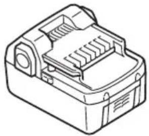
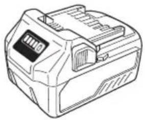
natural_image
Line drawing of a mechanical device with internal components (no text or symbols)BSL18.. BSL36..18
natural_image
Line drawing of a portable electronic device with control panel and buttons (no text or symbols)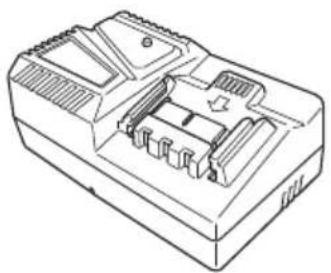
natural_image
Line drawing of a mechanical housing or enclosure with internal components (no text or symbols)UC18YFSL (14,4 V-18 V)
329897
natural_image
Technical line drawing of a mechanical housing component (no text or symbols)377353
natural_image
Line drawing of a quill pen with inkwell, no text or symbols present| English Dansk Slovenščina | |||
| GUARANTEE CERTIFICATE1 Model No.2 Serial No.3 Date of Purchase4 Customer Name and Address5 Dealer Name and Address(Please stamp dealer name and address) | GARANTIBEVIS1 Modelnummer2 Serienummer3 Købsdato4 Kundes navn og adresse5 Forhandlers navn og adresse(Indsæt stempel med forhandlers navn og adresse) | GARANCIJSKO POTRDILO1 Št. modela2 Serijska št.3 Datum nakupa4 Ime in naslov kupca5 Ime in naslov prodajalca(Prosimo vtisnite žig z imenom in naslovom prodajalca) | |
| Deutsch Norsk Slovenčina | |||
| GARANTIESCHEIN1 Modell-Nr.2 Serion-Nr.3 Kaufdatum4 Name und Anschrift des Kunden5 Name und Anschrift des Händlers(Bitte mit Namen und Anschrift des Handlers abstempeln) | GARANTISERTIFIKAT1 Modellnr.2 Serienr.3 Kjøpsdato4 Kundens navn og adresse5 Forhandlerens navn og adresse(Vennligst stemple forhandlerens navn og adresse) | ZÁRUČNÝ LISTA1 Č. modelu2 Sériové č.3 Dátum zakúpenia4 Meno a adresa zákaznika5 Názov a adresa predajcu(Pečiatka s názvom a adresou predajcu) | |
| Français Suomi Български | |||
| CERTIFICAT DE GARANTIE1 No. de modèle2 No de série3 Date d'achat4 Nom et adresse du client5 Nom et adresse du revendeur(Cachet portant le nom et l'adresse du revendeur) | TAKUUTODISTUS1 Malli nro2 Sarja nro3 Ostopäivämäärä4 Asiakkaan nimi ja osoite5 Myyjän nimi ja osoite(Leimaa myyjän nimi ja osoite) | ГАРАНЦИОНЕН СЕРТИФИКАТ1 Модел No2 Сериен No3 Дата за закупуване4 Име и адрес на клиента5 Име и адрес на търговеца(Моля, отпечатайте името и адрес на дилъра) | |
| Italiano Ελληνικά Srpski | |||
| CERTIFICATO DI GARANZIA1 Modello2 N° di serie3 Data di acquisto4 Nome e indirizzo dell'acquirente5 Nome e indirizzo del rivenditore(Si prega di apporre il timbro con questi dati) | ПІЗТОПОІНТИКО ЕГГУНЄНЄ1 Ap. Movтėlou2 Auξων Ap.3 Нμερομηνία αγοράς4 ́Оvoμα και δευθυνση πελάτη5 ́Оvoμα και δευθυνση μεταπωλητή(Παρακαλούμε να χρησιμοποιηθεί σφραγίδα) | GARANTNI SERTIFIKAT1 Br. modela.2 Serijski br.3 Datum kupovine4 Ime i adresa kupca5 Ime i adresa prodavca(Molimo da stavite pečat na ime i adresu trgovca) | |
| Nederlands Polski Hrvatski | |||
| GARANTIEBEWIJS1 Modelnummer2 Serienummer3 Datum van aankoop4 Naam en adres van de gebruiker5 Naam en adres van de handelaar(Stempel a.u.b. naam en adres vande de handelaar) | GWARANCJA1 Model2 Numer seryjny3 Data zakupu4 Nazwa klienta i adres5 Nazwa dealera i adres(Pieczęć punktu sprzedažy) | JAMSTVENI CERTIFIKAT1 Br modela.2 Serijski br.3 Datum kupnje4 Ime i adresa kupca5 Ime i adresa trgovca(Molimo stavite pečat na ime i adresu trgovca) | |
| Español Magyar | |||
| CERTIFICADO DE GARANTÍA1 Número de modelo2 Número de serie3 Fecha de adquisición4 Nombre y dirección del cliente5 Nombre y dirección del distribuidor(Se ruega poner el sello del distribuidor con su nombre y dirección) | GARANCIA BIZONYLAT1 Tipusszám2 Sorozatszám3 A vásárlás dátuma4 A Vásárló nevo és címe5 A Kereskedő neve és címe(Kérjük ide elhelyezni a Kereskedő nevének és címěnek pecsétjét) | ||
| Português Čeština | |||
| CERTIFICADO DE GARANTIA1 Número do modelo2 Número do série3 Data de compra4 Nome e morada do cliente5 Nome e morada do distribuidor(Por favor, carímbe o nome e morada do distribuidor) | ZÁRUČNÍ LIST1 Model č.2 Série č.3 Datum nákupu4 Jméno a adresa zákazníka5 Jméno a adresa prodejce(Prosíme o razitko se jménem a adresou prodejce) | ||
| Svenska Română | |||
| GARANTICERTIFIKAT1 Modellnr2 Serienr3 Inköpsdatum4 Kundens namn och adress5 Försäljarens namn och adress(Stámpla försäljarens namn och adress) | CERTIFICAT DE GARANTIE1 Model nr.2 Nr. de serie3 Data cumpărării4 Numele și adresa clientului5 Numele și adresa distribuitorului(Vá rugăm aplicați štampila cu numele și adresa distribuitorului) | ||
HiKOKI
| 1 | |
| 2 | |
| 3 | |
| 4 | |
| 5 |
Siemensring 34, 47877 willich, Germany
Tel: +49 2154 49930
Fax: +49 2154 499350
URL: http://www.hikoki-powertools.de
Hikoki Power Tools Netherlands B.V.
Brabanthaven 11, 3433 PJ Nieuwegein, The Netherlands
Tel: +31 30 6084040
Fax: +31 30 6067266
URL: http://www.hikoki-powertools.nl
Hikoki Power Tools (U.K.) Ltd.
Precedent Drive, Rooksley, Milton Keynes, MK 13, 8PJ,
United Kingdom
Tel: +44 1908 660663
Fax: +44 1908 606642
URL: http://www.hikoki-powertools.uk
Hikoki Power Tools France S.A.S.
Hikoki Power Tools Belgium N.V./S.A.
Koningin Astridlaan 51, B-1780 Wemmel, Belgium
Tel: +32 2 460 1720
Fax: +32 2 460 2542
URL http://www.hikoki-powertools.be
Hikoki Power Tools Italia S.p.A
Via Piave 35, 36077, Altavilla Vicentina (VI), Italy
Tel: +39 0444 548111
Fax: +39 0444 548110
URL: http://www.hikoki-powertools.it
Hikoki Power Tools Ibérica, S.A.
C/ Puigbarral, 26-28, Pol. Ind. Can Petit, 08227 Terrassa
(Barcelona), Spain
Tel: +34 93 735 6722
Fax: +34 93 735 7442
URL: http://www.hikoki-powertools.es
Kjeller Vest 7, N-2007 Kjeller, Norway
Tel: (+47) 6692 6600
Fax: (+47) 6692 6650
URL: http://www.hikoki-powertools.no
Hikoki Power Tools Sweden AB
Rotebergsvagen 2B SE-192 78 Sollentuna, Sweden
Tel: (+46) 8 598 999 00
Fax: (+46) 8 598 999 40
URL: http://www.hikoki-powertools.se
Hikoki Power Tools Denmark A/S
Lillebaeltsvej 90, 6715 Esbjerg N, Denmark
Tel: (+45) 75 14 32 00
Fax: (+45) 75 14 36 66
URL: http://www.hikoki-powertools.dk
Hikoki Power Tools Finland Oy
Tupalankatu 9, 15680 Lahti, Finland
Tel: (+358) 20 7431 530
Fax: (+358) 20 7431 531
URL: http://www.hikoki-powertools.fi
Hikoki Power Tools Hungary Kft.
Hikoki Power Tools Romania S.R.L.
Ring Road, No. 66, Mustang Traco Warehouses, Warehouse
No.1, Pantelimon City, 077145, Ilfov County, Romania


- GENERAL POWER TOOL SAFETY WARNINGS
- WARNING
- 1) Work area safety
- 2) Electrical safety
- 3) Personal safety
- 4) Power tool use and care
- 5) Battery tool use and care
- English
- PRECAUTION
- SAFETY WARNINGS COMMON FOR GRINDING OPERATIONS
- KICKBACK AND RELATED WARNINGS
- SAFETY WARNINGS SPECIFIC FOR GRINDING AND ABRASIVE CUTTING-OFF OPERATIONS
- GENERAL SAFETY INSTRUCTIONS FOR CORDLESS GRINDER
- ADDITIONAL SAFETY WARNINGS
- PRECAUTIONS FOR BATTERY AND CHARGER
- CAUTION ON LITHIUM-ION BATTERY
- CAUTION
- REGARDING LITHIUM-ION BATTERY TRANSPORTATION
- SYMBOLS
- STANDARD ACCESSORIES
- APPLICATIONS
- NOTE
- Electronic control
- CHARGING
- Disconnect the charger's power cord from the receptacle.
- Hold the charger firmly and pull out the battery. NOTE
- Regarding electric discharge in case of new batteries, etc.
- How to make the batteries perform longer.
- \*1 Installing a wheel (Fig. 5)
- \*2 Using the side handle
- \*3 Dial of variable speed operation
- Caution when using near welding equipment
- Precautions on operation
- Dressing the wheel
- WHEEL SELECTING METHOD
- MAINTENANCE AND INSPECTION
- Inspecting the wheel
- Inspecting the mounting screws
- Maintenance of the motor
- Inspection of terminals (tool and battery)
- Cleaning on the outside
- Cleaning the filter
- Storage
- SELECTING ACCESSORIES
- Important notice on the batteries for the HiKOKI cordless power tools
- GUARANTEE
- Information concerning airborne noise and vibration
- \*2 Usar a pega lateral
- BETEGNELSER FOR DELE
- (Fig. 1–Fig. 10)
- VEDLIKEHOLD OG INSPEKSJON
- ADVARSEL
- DODATNA VARNOSTNA OPOZORILA
- Hikoki Power Tools Netherlands B.V.
- Hikoki Power Tools (U.K.) Ltd.
- Hikoki Power Tools France S.A.S.
- Hikoki Power Tools Belgium N.V./S.A.
- Hikoki Power Tools Italia S.p.A
- Hikoki Power Tools Ibérica, S.A.
- Hikoki Power Tools Sweden AB
- Hikoki Power Tools Denmark A/S
- Hikoki Power Tools Finland Oy
- Hikoki Power Tools Hungary Kft.
- Hikoki Power Tools Romania S.R.L.
Brand : HiKOKI
Model : GP18DB
Category : Sander