
EWAQ-E-XR - Computer cooling system DAIKIN - Free user manual and instructions
Find the device manual for free EWAQ-E-XR DAIKIN in PDF.

| Product type | Computer hardware cooling system (air-cooled chiller) |
| Brand | Daikin |
| Model | EWAQ-E-XR |
| Category | Computer hardware cooling system |
| Condensation type | Air-cooled |
| Refrigerant | R410A |
| Global warming potential (GWP) | 2087,5 |
| Power supply | Three-phase 400V/50Hz (industrial standard) |
| Compressor | Scroll type |
| Evaporator | Integrated anti-freeze protection by electric heater down to -25°C |
| Condenser | Air-cooled, condenser coils |
| Anti-freeze protection | Electric heater with thermostat, supplemented by glycol if necessary |
| Flow switch | Mandatory, calibrated at 50% of nominal flow, IP67 |
| Noise level | Varies by model, indicated in commercial documentation |
| Operating limits | Ambient temperature: -20°C to +42°C; max RH 95% without condensation |
| Installation type | Outdoor (balcony, ground) on solid foundation, respect minimum distances |
| Materials | Metal, plastic and electronic components |
| Maintenance | Weekly, monthly and annual program (see manual table) |
| Safety | Yellow lifting points, main switch, electrical protection, sharp edges |
| Repairability | Authorized technical support, genuine parts available |
| Warranty | 12 months from first commissioning or 18 months after delivery |
| Water treatment | Respect limits: pH 6,8-8,0; conductivity <800 µS/cm; iron <1,0 mg/l |
| Heat recovery function | Optional, minimum water temperature 28°C |
| Provided documentation | Electrical diagrams, nameplate, declaration of conformity |
Frequently Asked Questions - EWAQ-E-XR DAIKIN
User questions about EWAQ-E-XR DAIKIN
0 question about this device. Answer the ones you know or ask your own.
Ask a new question about this device
Download the instructions for your Computer cooling system in PDF format for free! Find your manual EWAQ-E-XR - DAIKIN and take your electronic device back in hand. On this page are published all the documents necessary for the use of your device. EWAQ-E-XR by DAIKIN.
USER MANUAL EWAQ-E-XR DAIKIN
Installation, Operation and Maintenance Manual
D-EIMAC00808-16EU
Air cooled scroll chiller
EWAQ\~E- / EWAQ\~F-
SS (Standard Efficiency - Standard Noise)
SL (Standard Efficiency - Low Noise)
SR (Standard Efficiency - Extra Low Noise)
XS (High Efficiency - Standard Noise)
XL (High Efficiency - Low Noise)
XR (High Efficiency - Extra Low Noise)
Cooling capacity from 171 to 675 kW
Refrigerant: R410A
natural_image
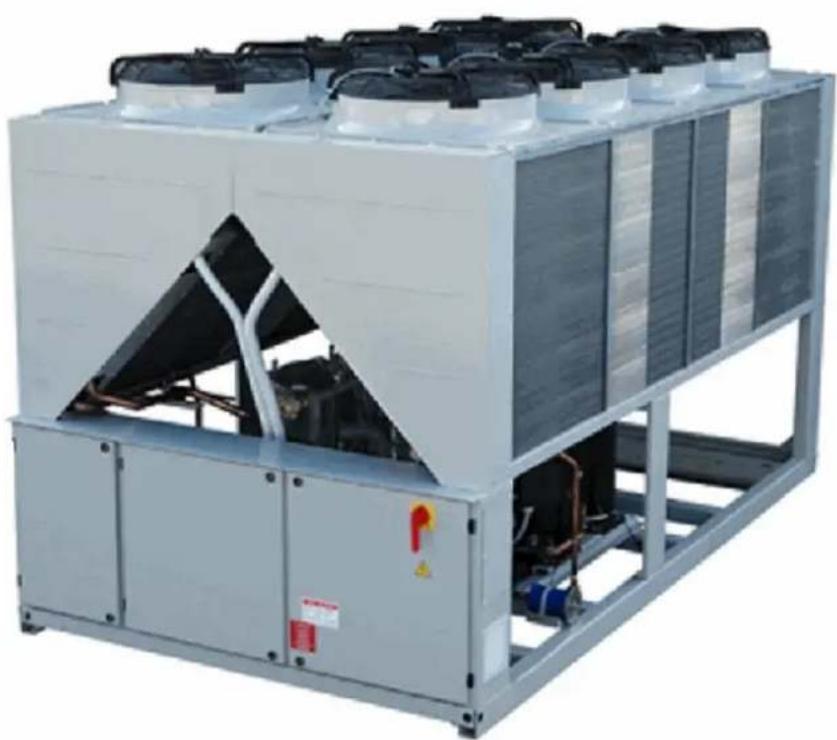
Large industrial cooling unit with multiple cooling units mounted on a metal frame (no visible text or symbols)English language: Original Instructions
All other language: Translation of the Original Instructions

English 9
Deutsch...... 21
Français .... 33
Nederlands..... 45
Español ..... 57
Italiano 69
Ελληνικά ...... 81
Português ..... 93
Русский ..... 105
Svenska ..... 117
Norsk 129
Finnish (Suomi) 14
Polski 153
Čech 165
Hrvat 177
Magyar ..... 189
Română ..... 201
Slovensky..... 213
Български ..... 225
Slovenščina .... 237

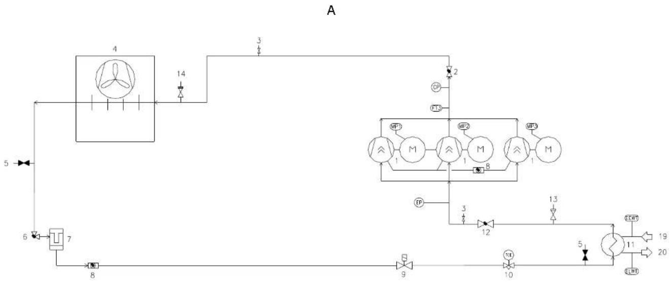
A – Typical refrigerant circuit – The number of compressors and water inlet and outlet are indicative. Please refer to the machine dimensional diagrams for exact water connections.
A – Typischer Kältemittelkreislaufs – Die Anzahl der Verdampfer und Wasserzu- und ablauf haben Beispielcharakter. Für die genauen Wasseranschlüsse bitte in den Zeichnungen zur Maschinebemessung nachsehen.
A – Circuit du réfrigérant typique – Le numéro des compresseurs et des entrées et sorties de l'eau est indicatif. Consulter les schémas de dimensions de la machine pour avoir des indications plus précises sur les connexions de l'eau.
A – Typisch koelcircuit - Het aantal compressors en waterin- en uitlaten is indicatief. Raadpleeg de schema's van de machine voor de exacte wateraansluitingen.
A – Circuito de refrigeración típico – El número de los compresores y de las entradas y salidas de agua es indicativo. Por favor, consulte los diagramas de la máquina para conocer las conexiones hidráulica exactas.
A – Circuito del refrigerante tipico – Il numero dei compressori e degli ingressi e uscite dell'acqua è indicativo. Consultare i disegni dimensionali della macchina per indicazioni più precise sulle connessioni dell'acqua.
Α – Τυπικό ψυκτικό κύκλωμα – Ο αριθμός των συμπιεστών και το νερό εισόδου και εξόδου είναι ενδεικτικά. Παρακαλώ ανατρέξτε στα διαγράμματα διαστάσεων του μηχανήματος για τις ακριβείς συνδέσεις νερού.
A – Circuito do refrigerante típico – O número de compressores e de ingressos e saídas da água é indicativo. Consultar os desenhos dimensionais da máquina para obter indicações mais exatas sobre as conexões da água.
А – Обычный контур хладагента - Количество компрессоров, входов и выходов воды - ориентировочное. Более подробные указания по подключению воды найдёте в чертежах, содержащих размеры машины.
A – Typisk köldmediekretsen - Äntalet kompressorer och vatten inlopp och utlopp är vägledande. Se maskinens dimensionsritningarna för exakta vattenanslutning.
A – Typisk kjølekrets – Antall kompressorer, vanninnløp og vannutløp er veiledende. Vennligst referer til maskinens mådiagrammer for nøyaktige vannkoblinger.
A – Tyypillinen jäähdytysjärjestelmä – Kompressorien ja veden tulojen ja poistojen lukumäärä on osoittava. Viittaa koneen mitoituspiirroksiin vesiliitäntöihin liittyvää yksityiskohtaisempaa tietoa varten.
A – Typowy obwód chłodzenia – Liczba sprężarek oraz wlotu i wylotu wody są wskazujące. Co do dokładnych połączeń wody prosimy odnieść się do schematów wymiarowych urządzenia.
A – Typický chladící okruh - Počet kompresorů a vodních vstupů a výstupů je orientační. Konzultujte rozměrové výkresy stroje pro přesnější informace o vodovodních přípojkách.
A – Tipičan rashladni krug – Broj kompresora i ulaza i izlaza za vodu su samo indikativni. Molimo vas pogledajte dijagrame o dimenzijama stroja radi što točnijeg položaja priključaka za vodu.
A – Tipikus hütőkör – A kompresszorok és a víz bemeneti és kimeneti csatlakozási pontjainak száma meghatározó. A pontos vízcsatlakozási jellemzőkért kérjük, tekintse meg a gép jellemzőit tartalmazó diagramokat.
A – Circuit de răcire caracteristic – Numărul compresoarelor și al punctelor de intrare și ieșire a apei sunt indicative. Vă rugăm consultați diagramele dimensionale ale mașinii pentru determinarea conexiunilor exacte pentru apă.
A – Typický chladiaci okruh – Počet kompresorov a vodných vstupov a výstupov je orientačný. Konzultujte rozmerové výkresy stroja pre presnejšie informácie o vodných prípojkách.
A – Типична схема за охлаждане – Броят на компресорите и водните входове и изходи са примерни. Моля направете справка, с диаграмата с размерите на машината, за точния брой на водните връзки.
A – Značilni krogotok hladilnega sredstva. Število kompresorjev in dovodov ter odvodov za vodo je okvirno. Priključki za vodo so natančneje prikazani na merskih risbah naprave.
flowchart
graph TD
    A["4"] --> B["14"]
    B --> C["3"]
    C --> D["2"]
    D --> E["CP"]
    D --> F["PT3"]
    E --> G["MP1"]
    E --> H["MP2"]
    E --> I["MP3"]
    G --> J["M"]
    H --> K["M"]
    I --> L["M"]
    J --> M["B"]
    K --> N["B"]
    L --> O["B"]
    M --> P["EP"]
    N --> Q["3"]
    O --> R["12"]
    P --> S["13"]
    Q --> T["10"]
    R --> U["5"]
    S --> V["11"]
    T --> W["19"]
    U --> X["20"]
    V --> Y["ELWT"]
    W --> Z["ELWT"]
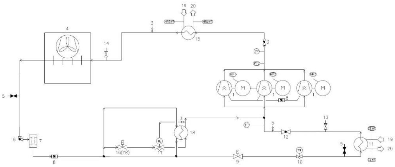
B – Typical refrigerant circuit with heat recovery – The number of compressors and water inlet and outlet are indicative. Please refer to the machine dimensional diagrams for exact water connections.
B – Typischer Kältemittelkreislaufs Wärmerückgewinnung – Die Anzahl der Verdampfer und Wasserzu- und ablauf haben Beispielcharakter. Für die genauen Wasseranschlüsse bitte in den Zeichnungen zur Maschinebemessung nachsehen.
B – Circuit du réfrigérant typique avec dispositif de récupération de la chaleur – Le numéro des compresseurs et des entrées et sorties de l'eau est indicatif. Consulter les schémas de dimensions de la machine pour avoir des indications plus précises sur les connexions de l'eau.
B – Typisch koelcircuit met warmteterugwinning - Het aantal compressors en waterin- en uitlaten is indicatief. Raadpleeg de schema's van de machine voor de exacte wateraansluitingen.
B – Circuito de refrigeración típico con recuperación de calor – El número de los compresores y de las entradas y salidas de agua es indicativo. Por favor, consulte los diagramas de la máquina para conocer las conexiones hidráulica exactas.
B – Circuito del refrigerante tipico con dispositivo di recupero del calore – Il numero dei compressori e degli ingressi e uscite dell'acqua è indicativo. Consultare i disegni dimensionali della macchina per indicazioni più precise sulle connessioni dell'acqua.
Β – Τυπικό ψυκτικό κύκλωμα με ανάκτηση θερμότητας – Ο αριθμός των συμπιεστών και το νερό εισόδου και εξόδου είναι ενδεικτικά. Παρακαλώ ανατρέξτε στα διαγράμματα διαστάσεων του μηχανήματος για τις ακριβείς συνδέσεις νερού.
B – Circuito do refrigerante típico com dispositivo de recuperação do calor - O número dos compressores e dos ingressos e saídas da água é indicativo. Consultar os desenhos dimensionais da máquina para indicações mais exatas sobre as conexões da água.
В – Обычный контур хладагента с устройством для утилизации теплоты - Количество компрессоров, входов и выходов воды - ориентировочное. Более подробные указания по подключению воды найдёте в чертежах, содержащих размеры машины.
B – Typisk köldmediekretsen med värmeåtervinning - Antalet kompressorer och vatten inlopp och utlopp är vägledande. Se maskinens dimensionella diagram för exakta vattenanslutningar.
B – Typisk kjølekrets med varmegjenvinning – Antall kompressorer, vanninnløp og vannutløp er veiledende. Vennligst referer til maskinens måldiagrammer for nøyaktige vannkoblinger.
B – Tyypillinen jäähdytysjärjestelmä lämmön talteenotolla – Kompressorien ja veden tulojen ja poistojen lukumäärä on osoittava. Viittaa koneen mitoituspiirroksiin vesiliitäntöihin liittyvää yksityiskohtaisempaa tietoa varten.
B – Typowy obwód chłodzenia z odzyskiwaniem ciepla – Liczba sprężarek oraz wlotu i wylotu wody są wskazujące. Co do dokładnych połączeń wody prosimy odnieść się do schematów wymiarowych urządzenia.
B – Typický chladící okruhse zařízením na rekuperaci tepla - Počet kompresorů a vodních vstupů a výstupů je orientační. Konzultujte rozměrové výkresy stroje pro přesnější informace o vodovodních připojkách.
B – Tipičan rashladni krug s povratom topline – Broj kompresora i ulaza i izlaza za vodu su samo indikativni. Molimo vas pogledajte dijagrame o dimenzijama stroja radi što točnijeg položaja priključaka za vodu.
B – Tipikus hütőkör hővisszanyerővel– A kompresszorok és a víz bemeneti és kimeneti csatlakozási pontjainak száma meghatározó. A pontos vizcsatlakozási jellemzőkért kérjük, tekintse meg a gép jellemzőit tartalmazó diagramokat.
B – Circuit de răcire cu recuperare de căldură caracteristic – Numărul compresoarelor și al punctelor de intrare și ieșire a apei sunt indicative. Consultați diagramele dimensionale ale mașinii pentru identificarea exactă a conexiunilor de apă.
B – Typický chladiaci okruh so zariadením na rekuperáciu tepla – Počet kompresorov a vodných vstupov a výstupov je orientačný. Konzultujte rozmerové výkresy stroja pre presnejšie informácie o vodných prípojkách.
В – Типична схема за охлаждане с използване на топлина – Броят на компресорите и водните входове и изходи са примерни. Моля направете справка, с диаграмата с размерите на машината, за точния брой на водните връзки.
B – Značilni krogotok hladilnega sredstva z rekuperacijo toplote. Število kompresorjev in dovodov ter odvodov za vodo je okvirno. Priključki za vodo so natančneje prikazani na merskih risbah naprave.
flowchart
graph TD
    A["4"] --> B["14"]
    B --> C["3"]
    C --> D["15"]
    D --> E["2"]
    E --> F["1"]
    F --> G["MP1"]
    F --> H["MP2"]
    F --> I["MP3"]
    G --> J["M"]
    H --> K["M"]
    I --> L["M"]
    J --> M["16(YR)"]
    K --> N["17"]
    L --> O["18"]
    M --> P["12"]
    N --> Q["10"]
    O --> R["9"]
    P --> S["13"]
    Q --> T["11"]
    R --> U["20"]
    S --> V["19"]
    T --> W["20"]
    X["5"] --> Y["6"]
    Z["8"] --> AA["7"]
| ENGLISH | DEUTSCH | FRANÇAIS | NEDERLANDS | ESPAÑOL | ITALIANO | ΕΛΛΗΝΙΚΑ | |
| 1 | Compressor | Verdichter | Compresseur | Compressor | Compressor | Compressore | Συμπιστής |
| 2 | Discharge shut off valve | Absperrventil Druckleitung | Robinet d'évacuation | Alvorderklop | Válvula de cierre de descarga | Rubinetto di scarico | Εκφαρθωση βαλβίδας κλισμίντος |
| 3 | 1⁄4 SAE Flare Valve | 1⁄4 SAE Flare Ventil | Vanne 1⁄4 SAE Flare | 1⁄4 SAE Oprulinklep | Válvula 1⁄4 SAE Flare | Valvola 1⁄4 SAE Flare | 1⁄4 SAE φυτοβολία βαλβίδας |
| 4 | Condenser coil and Axial ventilator | Verflüssigerregister und Axialventilator | Batterie & condensation et ventilateur axial | Condensatorwikkeling en Axiale ventilator | Serpentin del condensador y Ventilador axial | Batteria condensante e ventilatore assiale | Πηγα συμπικωτη και Αξωνικός ανενωτήρας |
| 5 | Service port | Betriebsanschluss | Port de maintenance | Diensport | Abertura de servicio | Portello per assistenza | Υπηρεσία θηρας |
| 6 | Liquid line isolating valve | Selbstschlussventil Flüssigkeitseitling | Vanne disollement de la ligne du liquide | Afsluitklep viceistifijn | Válvula de aislamiento de la línea del líquido | Valvola isolante línea del líquido | Γραμήν υγρού βαλβίδας απομώνοσης |
| 7 | Dehydration filter | Entwässerungsfilter | Filtre déshydrateur | Dehydratatefilter | Filtro deshidrator | Filtro deidratatore | Φίλτρο αφυάστωσης |
| 8 | Liquid and humidity indicator | Flüssigkeits- und Feuigmigkeitsanzeiger | Indicateur de liquide et humidité | Indictar vloeistof en vochtigheid | Indicador de líquido y humedad | Indicatore di líquido e umidità | Υγρό και δείκης υγρασίας |
| 9 | Solenoid valve | Sovenoidventil | Vanne solenolde | Elektromagnetsche kiep | Válvula solenoide | Valvola solenoide | Ηπεκτρουγμντική βαλβίδα |
| 10 | Electronic expansion valve | Elektronisches Expansionsventil | Détendeur électronique | Elektronische expansiekiep | Válvula de expansión electrónica | Valvola di espansione electronica | Ηπεκτρωνική βαλβίδα εκτώνωσης |
| 11 | Evaporator | Verdampler | Evaporator | Verdamper | Evaporador | Evaporatore | Εξεμπιστής |
| 12 | Suction shut off valve | Absperrventil Ansaugleitung | Robinet d'aspiration | Afsluitklep aanziging | Válvula de cierre aspiración | Rubinetto di aspirazione | Αναρρόρηση βαλβίδας κλισμίντος |
| 13 | Low-pressure safety valve | Niederdruck-Sicherheitsventil | Soupape de sécurité à basse pression | Veilighedisklep lage cruk | Válvula de seguridad de baja pression | Valvola di sicurezza a bassa pressione | Χαμηλή-πίεση βαλβίδας ασφαλείας |
| 14 | High-pressure safety valve | Hochdruck-Sicherheitsventil | Soupape de sécurité haute pression | Veilighedisklep hoge druk | Válvula de seguridad de alta pression | Valvola di sicurezza alta pressione | Υψηλή-πίεση βαλβίδας ασφαλείας |
| 15 | Heat recovery (optional) | Wärmerückgewinnung (optional) | Dispositif de récupération de la chaleur (en option) | Inrichting voor warmtelerugwinning (opfle) | Recuperador de calor (optional) | Dispositivo di recupero del calore (opzionale) | Ανάκτηση θερμότητας (προσαρτικό |
| 16 (YR) | Heat recovery solenoid valve (only for total heat recovery version) | Soienoidventil Wärmerückgewinnung (nur für Version mit totaler Wärmerückgewinnung) | Vanne solenolde de récupération de la chaleur (seulement dans la version à récupération totale de la chaleur) | Elektomagnetsche kiep warmieterugwinning (alleen voor versie met totale warmieterugwinning) | Válvula solenoide del recuperador de calor (sólo para versión con recuperador de calor total) | Valvola solenoide recupero del calore (sólo nella versione a recupero totale del calore) | Ανάκτηση θερμότητας πλεκτρουγμντικής βαλβίδας (μένο γιν έκδοση συνολικής ανάκτησης θερμότητας |
| 17 | Heat recovery thermostatic expansion valve (only for total heat recovery version) | Wärmerückgewinnung thermostatische Expansionsvent (nur für Version mit totaler Wärmerückgewinnung) | Détendeur thermostatique du dispositif de récupération de la chaleur (seulement dans la version à récupération totale de la chaleur) | Thermostatische expansieklep warmieterugwinning (alleen voor versie met totale warmieterugwinning) | Válvula de expansión termostática del recuperador de calor (sólo para versión con recuperador de calor total) | Valvola di espansione termostatica dispositivo di recupero del calore (sólo nella versione a recupero totale del calore) | Εφρωστοπική ανάκτηση θερμότητας βαλβίδας εκτώνωσης (μένο γιν έκδοση συνολικής ανάκτησης θερμότητας) |
| 18 | Subcooler (only for total heat recovery version) | Unterkühler (nur für Version mit totaler Wärmerückgewinnung) | Sous-refroidisseur seulement dans la version à récupération totale de la chaleur) | Nakosier (alleen voor versie met totale warmtelerugwinning) | Subenfriador (sólo para versión con recuperador de calor total) | Soltoraffreddalore (sólo nella versione a recupero totale del calore) | Υπομύκης (μένο γιν έκδοση συνολικής ανάκτησης θερμότητας) |
| 19 | Water inlet connection | Wasserzulautanschluss | Connexion entree eau | Aansluitting waterinlaat | Connexion de entrada de agua | Connessione ingresso acqua | Συνέσεη νερου εσόδου |
| 20 | Water outlet connection | Wasserabiatanschluss | Connexion sortie eau | Aansluitting waterinlaat | Connexion de salida de agua | Connessione uscita acqua | Συνέσεη νερου εσόδου |
| EP | Low-pressure transducer | Niederdruckwandler | Transductor basse pression | Transductor lage druk | Transductor de baja presión | Trasduttore bassa pressione | Χαμηλής πίεσης μεταρτοπέας |
| CP | High-pressure transducer | Hopdruckwandler | Transductor hauto pression | Transductor hogo druk | Transductor de alta presión | Trasduttore alta presión | Υψηλής πίεσης μεταρτοπέας |
| F13 | High-pressure switch | Maximum-Druckwächter | Pressostat de haute pression | Hogedrukschakelaar | Interruptor de alta presión | Pressostato di alta | Διακάττης υμηλής πίεσης |
| MP1 | Motor thermistor compressor 1 | Motorthermistor Verdichter 1 | Compresseur thermistance moteur 1 | Motor thermistor compressor 1 | Termistor del motor del compresor 1 | Compressore termistore motore 1 | Κινητήρας θερμοστατή συμπιστή |
| MP2 | Motor thermistor compressor 2 | Motorthermistor Verdichter 2 | Compresseur thermistance moteur 2 | Motor thermistor compressor 2 | Termistor del motor del compresor 2 | Compressore termistore motore 2 | Κινητήρας θερμοστατή συμπιστή 2 |
| MP3 | Motor thermistor compressor 3 | Motorthermistor Verdichter 3 | Compresseur thermistance moteur 3 | Motor thermistor compressor 3 | Termistor del motor del compresor 3 | Compressore termistore motore 3 | Κινητήρας θερμοστατή συμπιστή 2 |
| EEWT | Evaporator Entering Water Temperature probe | Temperaturfühler Wasserzulauf Verdampfer | Sonde de température de l'eau de l'évapourateur en entrée | Temperatuorsonde binnenstromend water verdamper | Sonda temperatura del agua en entrada en el evaporador | Sonda temperatura acqua evaporatore in ingresso | Εξαμπισής Θερχώμενου Νερου Θερμοκροσίας ανέθητρα |
| ELWT | Evaporator Leaving Water Temperature probe | Temperaturfühler Wasserablauf Verdampfer | Sonde de température de l'eau de l'évapourateur en sortie | Temperatuorsonde ulistromend water verdamper | Sonda temperatura del agua en salida del evaporador | Sonda temperatura acqua evaporatore in uscita | Εξαμπισής Θερχώμενου Νερου Θερμοκροσίας ανέθητρα |
| HREWT | Heat Recovery Entering Water Temperature probe (only for total heat recovery version) | Temperaturfühler Wasserzulauf Wärmerückgewinnung (nur für Version mit totaler Wärmerückgewinnung) | Sonde de température de l'entrée d'eau de récupération de chaleur (seulement dans la version à récupération totale de la chaleur) | Temperatuorsonde binnenstromend water warmieterugwinning (alleen voor versie met totale warmieterugwinning) | Sonda temperatura del agua en entrada en el recuperador de calor (sólo para versión con recuperador de calor total) | Sonda temperatura ingresso acqua recupero di calore (sólo nella versione a recupero totale del calore) | Ανάκτηση θερμότητος Εσόδου Νερου Θερμοκροσίας οωνθήρας (μένο γιν έκδοση συνολικής ανάκτησης θερμότητας) |
| HRLWT | Heat Recovery Leaving Water Temperature probe (only for total heat recovery version) | Temperaturfühler Wasserablauf Wärmerückgewinnung (nur für Version mit totaler Wärmerückgewinnung) | Sonde de température de la sortie d'eau de récupération de chaleur (seulement dans la version à récupération totale de la chaleur) | Temperatuorsonde ulistromend water warmieterugwinning (alleen voor versie met totale warmieterugwinning) | Sonda temperatura del agua en salida del recuperador de calor (sólo para versión con recuperador de calor total) | Sonda temperatura uscita acqua recupero di calore (sólo nella versione a recupero totale del calore) | Ανάκτηση θερμότητος Εξαρχώμενου Νερου Θερμοκροσίας οωνθήρας (μένο γιν έκδοση συνολικής ανάκτησης θερμότητας) |
| PORTUGUÊS | ΡΥССКИЙ | SVENSKA | NORSK | SUOMI | POLSKI | ČESKY | |
| 1 | Compressor | Kompressor | Kompressom | Kompressor | Kompressori | Sprzarka | Kompressor |
| 2 | Torneira de descarga | Сливной кран | Urladda avstängningsventil | avstengningsventil utlop | Poiston sulkuventtill | Wypływowy zawór ościnający | Vypoustęci kohout |
| 3 | Válvula 1⁄2 SAE Flare | Кланан 1⁄2 SAE Flare | Vs SAE Uftytning ventil | Vs SAE Fackelventil | Vs SAE Flare-venttill | Zawór stoczkowy 1⁄4 SAE | Ventil 1⁄2 SAE Flare |
| 4 | Bateria condensadora e ventilador axial | Змевник конденсатора и освою вентилятор | Kondensor spole och Axiell fläkt | Kondensatorbatteri og Akslalventilator | LauhoutlTMen klerukka ja akslaalinen puhalin | Węczownica skraplacza i Wentylator osowy | Konderzačni baterie a axialni ventilátor |
| 5 | Portlinhola para assistência | Сервисная дверца | Servicosporten | Servicelsuke | Huolcaukko | Port serwisowy | Słuzebni dvilka |
| 6 | Válvula isolante linha do liquido | Изолирующий клапан контура жидкости | Välskeledningen isolering ventil | Avstengningsventil på llytende linje | Nestelinjan sulkuventtill | Zawór oddzielający linii plynu | Ventil na izolaci kapalni linky |
| 7 | Filtro desidrator | Филър водоотделитель | Dehydratisering fitret | Avfuktningfilter | Kulvatusuodatin | Filtr odwadniecz | Sušići filtr |
| 8 | Indicador de líquido e humidade | Указатель жидкости и влажност | Flytande och tuktighets indikator | Vëske- og tuktighetsindikator | Neste- ja kosteusmittari | Wskaznik plynu i wilgotności | Ukazatei kapaliny a vlhkosti |
| 9 | Válvula solenóide | Solencoidный клапан | Solencoiden ventil | Magnetventil | Solencoidventtill | Zawór elektromagnetyczny | Solencoidi ventil |
| 10 | Válvula de expansão eletrónica | Электронный расширительный клапан | Elektronisk expansionsventil | Elektronisk ekspansjonsventil | Elektroninen paisuntsventtilli | Elektroniczny zawór rozprężny | Elektronický expanzní ventil |
| 11 | Evaporador | Испаритель | Förångaren | Evaporator | Haldhutin | Parownik | Vyparnik |
| 12 | Torneira de aspiração | Всасывающий кран | Supning avstängningsventil | Avstengningsventil innlop | Imun sulkuventtill | Ssawny zawór ościnający | Saci kohout |
| 13 | Válvula de segurança de baixa pressão | Предохранительный клапан низкого давления | Légt trick säkernets ventil | Sikkerhetsventil for lavtrykk | Alhaisen paineen varoventtill | Zawór bezpieczeństwa niskiego ciśnienia | Pojistný ventil nizkého tlaku |
| 14 | Válvula de segurança de alta pressão | Предохранительный клапан высокого давления | Högt tryck säkerhets ventil | Sikkerhetsventil for høytrykk | Korkean paineen varoventtill | Zawór bezpieczeństwa wysokiego ciśnienia | Pojistný ventil vysokého tlaku |
| 15 | Dispositivo de recuperação do calo (optional) | Устройство для утилизации теплоты (по запросу) | Värmeåtervinning (tillval) | Varmegjenvinning (billeggsulstyr) | Lämmön talteenolto (lisävaruste) | Odzyskiwanie ciepla (opcja) | Zaftzení na rekuperaci tepla (voliteiny prvek) |
| 16 (YR) | Válvula solenóide recuperação do calor (somente na versão de recuperação total do calor) | Solencoidный клапан утилизации тепла (только для версии полной утилизации тепла) | Värmeåtervinning magnetventil(endast för total värmeåtervinning version) | Magnetventil varmegjenvinning (kun for utgave total varmegjenvinning) | Lämmön talteenoton solenoidventtill (vain versossa, jossa lampó otetaan kokonaan talleen) | Zawór elektromagnetyczny odzyskiwania ciepla (tyko w wersji całkowitego odzyskania ciepla) | Solenoidni ventil na rekuperaci lepl (pouze u verzis kompletni rekuperaci tepla) |
| 17 | Válvula de expansão termostática dispositivo de recuperação do calor (somente na versão de recuperação total do calor) | Термостатический расширительный клапан устройства для утилизации теп (только для версии полной утилизации тепла) | Värmeåtervinning termostatisk espansionsventil(endast för total värmeåtervinning version) | Termostatisk espansjonsventil varmegjenvinning (kun for utgave total varmegjenvinning) | Lämmön talteenoton termostaattinen paisuntsventtill (vain versossa, jossa lampó otetaan kokonaan talleen) | Termostatyczny zawór rozprężny odzyskiwania ciepla (tyko w wersji całkowitego odzyskania ciepla) | Expanzni termostatický ventil zařizení na rekuperaci tepla (pouze u verzi s kompletni rekuperaci tepla) |
| 18 | Sub arrefecedor (somente na versão de recuperação total do calor) | Первохладитель (только для версии полной утилизации тепла) | Underkylare (endast för total värmeåtervinning version) | Underkjøler (kun for utgave total varmegjenvinning) | Alijäähdytin (vain versossa, jossa lampó otetaan kokonaan talleen) | Dochladzacz (tyko w wersji całkowitego odzyskania ciepla) | Podchłazovać (pouze u verzis kompletni rekuperaci tepla) |
| 19 | Conexão entrada água | Подсоединение входа воды | Vatteninloposansluitning | Forbindelse for vanninnlep | Veden tuliolitntă | Polączenie wlotowe wody | Phipojení vistupu vody |
| 20 | Conexão saída agua | Подсоединение выхода воды | Vatten utloop | Forbindelse for vannutlop | Veden poistolitantă | Polączenie wylotowe wody | Phipojení vystupu vody |
| EP | Transdutor baixa pressão | Преобразователь низкого давли | Lag-tryck-osmandaren | Lavtrykksomformer | Alhaisen paineen anturi | Przetwomik nisklego ciśnienia | Transdutor nizkého tlaku |
| CP | Transdutor alta pressão | Преобразователь высокого давления | Hög-tryck-givare | Høytrykksomformer | Korkeaspaineanturi | Przetwomik wysokiego ciśnienia | Transdutor vysokého tlaku |
| F13 | Pressóstato de alta | Реле высокого давления | Högtryckvakt | Høytrykksbyrter | Korkeapaine kytkin | Presostat wysokiego ciśnienia | Presostat vysokého tlaku |
| MP1 | Compressor temistor motor 1 | Компрессор термистор двигате | Motortermistor kompressor 1 | Motor termistor kompressor 1 | Moortorin termistori kompressor 1 | Temistor silnika spreżarik 1 | Kompressor motoru termistoru 1 |
| MP2 | Compressor temistor motor 2 | Компрессор термистор двигате | Motortermistor kompressor 2 | Motor termistor kompressor 2 | Moortorin termistori kompressor 2 | Temistor silnika spreżarik 2 | Kompressor motoru termistoru 2 |
| MP3 | Compressor temistor motor 3 | Компрессор термистор двигате | Motortermistor kompressor 3 | Motor termistor kompressor 3 | Moortorin termistori kompressor 3 | Temistor silnika spreżarik 3 | Kompressor motoru termistoru 3 |
| EEWT | Sonda de temperatura da água do evaporador em entrada | Датчик температуры воды испирителя на входе | Förångare ingaende valtentemperatur sond | Temperaturfoler Innlepsvann Evaporator | Haldhuttimen släsknmenevän veden lämpółila-anturi | Sonda Wejsciowej Temperature Wody Parownika | Cidlo teploty vody na vistupu vypamiki |
| ELWT | Sonda de temperatura da água do evaporador em salida | Датчик температуры воды испирителя на выходе | Utgäende Köldobrætemperatur sond | Temperaturfoler Utképsvann Evaporator | Haldhuttimen poistuvan veden lämpółila anturi | Sonda Wyjsciowej Temperature Wody Parownika | Cidlo teploty vody na vystupu vypamiki |
| HREWT | Sonda de temperatura de ingresso da água de recuperação do calor (somente na versão de recuperação total do calor) | Датчик температуры воды на вы устройства для утилизации теп (только для версии полной утилизации тепла) | Värme Älverinning Ange Vattenlemperatur sond (endast för total värmeåtervinning version) | Temperaturfoler for Varmegjenvinning Vanninnlep (kun for utgave total varmegjenvinning) | Lämmön talteenotto släsknmenevän veden lämpółila-anturi (vain versossa, jossa lampó otetaan kokonaan talleen) | Sonda Wejsciowej Temperature Wody Odzyskiwania Ciepla (tyko w wersji całkowitego odzyskania ciepla) | Cidlo teploty vody na vistupu zařizes na rekuperaci tepla (pouze u verzis kompletni rekuperaci tepla) |
| HRLWT | Sonda de temperatura de ingresso da água de recuperação do calor (somente na versão de recuperação total do calor) | Датчик температуры воды на выходе устройства для утилизации теплоты (только для версии по утилизации тепла) | Värme Älverinning Lämma Vattenlemperatur sond (endast för total värmeåtervinning version) | Temperaturfoler for Varmegjenvinning Vannutlap (kun for utgave total varmegjenvinning) | Lämmön talteenotto poistuvan veden lämpółila-anturi (vain versossa, jossa lampó otetaan kokonaan talleen) | Sonda Wyjsciowej Temperature Wody Odzyskiwania Ciepla (tyko w wersji całkowitego odzyskania ciepla) | Cidlo teploty vody na vistupu zařizes na rekuperaci tepla (pouze u verzis kompletni rekuperaci tepla) |
| HRVATSKI | MAGYAR | ROMANA | SLOVENSKY | БЪЛГАРСКИ | SLOVENSCINA | |
| 1 | Kompresor | Kompresszor | Compresor | Compressore | Komprecor | Kompresor |
| 2 | Veniliz za pražnjenje | Leereszló elázó szelop | Robinet de evacuare | Vypuláfić kohúlik | Kran za podavane | Zaporni venil izpusta |
| 3 | 1⁄4 SAE Flare Ventil | 1⁄4 SAE Kupos szelop | 1⁄4 SAE Valvá conică | Ventil 1⁄4 SAE Flare | Klapan 1⁄4 SAE Flare | Ventil s priključkom SAE Flare 1⁄4 |
| 4 | Zavojnica kondenzatoria i Aksjalni ventilator | Höceserő lemezelt csökigyó és Axití ventilátor | Balerie de condensare și Ventilator axial | Konderzačná balória a axiálny ventilátor | Kondenzeniarača bateria i ventilatior za inbezekdané | Navije kondenzatorja in osni ventilator |
| 5 | Virata za servisiranje | Szerviz port | Uşa pentru asistența | Služobne dvierka | Obcluyvač maj | Servina odprtina |
| 6 | Izolacijski ventil linije za tekućinu | Folyadék vezeték elázó szelop | Valvá izolare line de lichid | Ventil na izolaciu kvapalnej linky | Isojiruprak klapan linnia na tectnostta | Loblil ventil cevi za tekočine |
| 7 | Dehidratacijski filter | Vizlevaisztó szluró | Filtru deshidrator | Sušlaci filter | Dexkiratriarc filiptr | Filter za osuštev |
| 8 | Indikator vlažnosli i tekućine | Folyadék és páratalialom jelző | Indicalor de lichid și umiditate | Ukazovatel kvaliny a vihkosti | Indickato za tenocst i vajnoost | Kazalnik lekočin in vlage |
| 9 | Elektrčni ventil | Szolenoid szelop | Valvá solenoidă | Solenoidny ventil | Klapan zarejedane | Elektromagneti ventil |
| 10 | Venil za elektronsku ekspanziju | Elektromos laqulasi szelop | Valvá electronică de expansiune | Expanzy elektroniký ventil | Elektronen zasirinitelen klanan | Elektronski ekspanzijski ventil |
| 11 | Ispanvač | Párologátó | Evaporator | Vypsnik | Inapritel | Evaporator |
| 12 | Usani ventil | Szivů oldali elázó szelop | Robinet de aspiratie | Sací kohúlik | Kran za sacumvane | Zaporni ventil za sesanje |
| 13 | Sigumosni ventil niskog tlaka | Biztonsági szelop elégten nyoma elkretileșere | Valvá de siguranța jossa presiune | Poistny ventil nizkeho tlaku | Predlazen klapan za hinsko najlagan | Nizkotlačni vamostni ventil |
| 14 | Sigumosni ventil visokog tlaka | Biztonsági letvátó szelop | Valvá de siguranța inaltă presiune | Poistny ventil vysokého tlaku | Predlazen klapan za hisico najlagane | Visokotlačni vamostni ventil |
| 15 | Povrat topline (optionalno) | Hôvisszanyerő (opcós) | Recuperare de caldură (opcjional) | Zariadenie na rekuperáciu tepla (volletný prvk) | Toplloobmenink (opcion) | Rekuperacija toplote (lodatna možnost) |
| 16 (YR) | Elektromagnetski ventil za povrat topline (isključivo za verziju toalnog povrata topline) | Hôvisszanyerő szolenoid szelop (csak teljes hôvisszanyerő egység esetén) | Valvá solenoidă recuperare de caldură (numai pentru versiunea cu recuperare totală de caldură) | Solenoidny ventil na rekuperáciu tepla (iba vo verzii s kompletnou rekuperáciou tepla) | Toplloobmenink klapan zarejedane (samo pri modulinte s plynha tollinnna regenerația) | Elektromagneti ventil za rekupersiclo toplote (samo pri različici s popolno rekuperacijo toplote) |
| 17 | Termostatički ekspanzioni ventil za povrat topline (isključivo za verziju totalnog povrata topline) | Hôvisszanyerő termosztatikus működésű tegulási szelop (csak teljes hôvisszanyerő egység esetén) | Valvá termostatică de expansiune recuperare de caldură (numai pentru versiunea cu recuperare totală de caldură) | Termostaticky expanzy ventil zariadenia na rekuperácuo tepla (iba vo verzii s kompletnou rekuperáciou tepla) | Termostatianen zasirinitelen klapan inkomink | Termostatski ekspanzijaki ventil za rekupersiclo toplote (samo pri različici s popolno rekuperacijo toplote) |
| 18 | Pothladivač (isključivo za verziju totalnog povrata topline) | Subcooler (csak teljes hôvisszanyerő egység esetén) | Subracitor (numai pentru versiunea cu recuperare totală de caldură) | Podchladzovač (iba vo verzii s kompletnou rekuperáciou tepla) | Modul za svrъхохлаждане | Dodatni hladinik (samo pri različici s popolno rekupersiclo toplote) |
| 19 | Priključak za ulaznu vodu | Bemenő vizssonik | Conexiune intrare apă | Pripojenie vistupu vody | Brýzka вход voda | Dovodni priključek za vodo |
| 20 | Priključak za izlaznu vodu | Kimenő oldali vizssonik | Conexiune ieşire apă | Pripojenie vystupu vody | Brýzka inoxod voda | Odvodni priključek za vodo |
| EP | Pretvomik niskog tlaka | Alacsony nyomás távadó | Traductor jossa presiune | Transduktor nizkeho tlaku | Konvertor nicsko najlagane | Pretvomik nizkega tlaka |
| CP | Pretvomik visokog tlaka | Nagy nyomás távadó | Traductor inaltă presiune | Transduktor vysokého tlaku | Konvertor inosico najlagane | Pretvomik visokega tlaka |
| F13 | Visokotlačna sklopka | Nagy nyomás nyomáskapcosoló | Înterupátor inaltă presiune | Presostat vysokého tlaku | Kontaktor opanrachitel nicsko najlagane | Visokotlačne stikalo |
| MP1 | Motor termistora kompresor 1 | 1. kompresszor motor termisztora | Motor compresor cu protectie termic 1 | Kompresor motora termistoru 1 | Predlaznie termikstorii kompresor 1 | Termistor motorja - kompresor 1 |
| MP2 | Motor termistora kompresor 2 | 2. kompresszor motor termisztora | Motor compresor cu protectie termic 2 | Kompresor motora termistoru 2 | Predlaznie termikstorii kompresor 2 | Termistor motorja - kompresor 2 |
| MP3 | Motor termistora kompresor 3 | 3. kompresszor motor termisztora | Motor compresor cu protectie termic 3 | Kompresor motora termistoru 3 | Predlaznie termikstorii kompresor 3 | Termistor motorja - kompresor 3 |
| EEWT | Ispanivač sonda za Temperaturu Ulazne Vode | A Párologatóba Belépů Viz Hómersekelzékejle | Sondá de temperatură intrare apă evaporator | Sonda teploty vody na vistupe vypamika | Temperaturna sonda вход voda | Sonda za temperaturo vode, ki vstopa v uparjalnik |
| ELWT | Ispanivač sonda za Temperaturu Izizane Vode | A Párologatóból Kilépő Viz Hómersekelzékejle | Sonda temperatură ieşire apă evaporator | Sonda teploty vody na vistupe vypamika | Temperaturna sonda inoxod voda | Sonda za temperaturo vode, ki Izstopa iz uparjalnika |
| HREWT | Povrat Topline Sonda za temperaturu Ulazne vode (isključivo za verziju totalnog povrata topline) | A Hôvisszanyerőbe Belépů Viz Hómersekelzékejle (csak teljes hôvisszanyerő egység esetén) | Sonda temperatură intrare apă recuperare de caldură (numai pentru versiunea cu recuperare totală de caldură) | Sonda teploty vody na vistupe zariadenia na rekuperácuu tepla (iba vo verzii s kompletnou rekuperáciou tepla) | Toplloobmenink Viod Boda Temperaturna sonda (samo pri modulinte s plynha tollinnna regenerația) | Sonda za temperaturo vode, ki vstopa v rekuperator i toplote (samo pri različici s popolno rekuperacijo toplote) |
| HRLWT | Povrat Topline Sonda za temperaturu Ulazne vode (isključivo za verziju totalnog povrata topline) | A Hôvisszanyerőbő Bilépő Viz Hómersekelzékejle (csak teljes hôvisszanyerő egység esetén) | Sonda temperatură ieşire apă recuperare de caldură (numai pentru versiunea cu recuperare totală de caldură) | Sonda teploty vody na vistupe zariadenia na rekuperácuu tepla (iba vo verzii s kompletnou rekuperáciou tepla) | Toplloobmenink Изod Boda Temperaturna sonda (samo pri modulinte s plynha tollinnna regenerația) | Sonda za temperaturo vode, ki Izstopa iz rekuperatorja toplote (samo pri različici s popolno rekuperacijo toplote) |
This manual is an important supporting document for qualified personnel but it is not intended to replace such personnel.
Thank you for purchasing this chiller

READ THIS MANUAL CAREFULLY BEFORE INSTALLING AND STARTING UP THE UNIT. IMPROPER INSTALLATION COULD RESULT IN ELECTRIC SHOCK, SHORT-CIRCUIT, LEAKS, FIRE OR OTHER DAMAGE TO THE EQUIPMENT OR INJURE TO PEOPLE. THE UNIT MUST BE INSTALLED BY A PROFESSIONAL OPERATOR/TECHNICIAN. UNIT STARTUP HAS TO BE PERFORMED BY AUTHORIZED AND TRAINED PROFESSIONAL. ALL ACTIVITIES HAVE TO BE PERFORMED ACCORDING TO LOCAL LAWS AND REGULATION. UNIT INSTALLATION AND START UP IS ABOSOLUTELY FORBIDDEN IF ALL INSTRUCTION CONTAINED IN THIS MANUAL ARE NOT CLEAR. IF CASE OF DOUBT CONTACT THE MANUFACTURER REPRESENTATIVE FOR ADVICE AND INFORMATION.
Description
The unit you bought is an "air cooled chiller", a machine aimed to cool water (or water-glycol mixture) within the limits described in the following. The unit operation is based on vapour compression, condensation and evaporation according to reverse Carnot cycle. The main components are:
- Scroll compressor to rise the refrigerant vapour pressure from evaporation pressure to condensation pressure.
- Evaporator, where the low pressure liquid reqrigerant evaporates so cooling the water.
- Condenser, where high pressure vapour condensate rejecting heat removed from the chilled water in the atmosphere thanks to an air cooled heat exchanger.
- Expansion valve allowing to reduced the pressure of condensed liquid from condensation pressure to evaporation pressure.
General Information

All units are delivered with wiring diagrams, certified drawings, nameplate; and DOC (Declaration Of Conformity); these documents show all technical data for the unit you have bought and they MUST BE
CONSIDERED ESSENTIAL DOCUMENTS OF THIS MANUAL
In case of any discrepancy between this manual and the equipment's documents please refer to on board documents. In case of any doubt contact the manufacturer representative. The purpose of this manual is to allow the installer and the qualified operator to ensure proper installation, commissioning and maintenance of the unit, without any risk to people, animals and/or objects.
Receiving the unit
The unit must be inspected for any possible damage immediately upon reaching final place of installation. All components described in the delivery note must be inspected and checked.
Should the unit be damaged, do not remove the damaged material and immediately report the damage to the transportation company and request they inspect the unit. Immediately report the damage to the manufacturer representative, a set of photographs are helpful in recognizing responsibility
Damage must not be repaired before the inspection of the transportation company representative.
Before installing the unit, check that the model and power supply voltage shown on the nameplate are correct.
Responsibility for any damage after acceptance of the unit cannot be attributed to the manufacturer.
Operating limits
Storing
Environmental conditions must be within the following limits:
Minimum ambient temperature : -20^
Maximum ambient temperature : +42°C
Maximum R.H. : 95% not condensing
Storing below the minimum temperature may cause damage to components. Storing above the maximum temperature causes opening of safety valves. Storing in condensing atmosphere may damage electronic components.
Operation
Operation out of the mentioned limits may damage the unit. In case of doubts contact manufacturer representative.
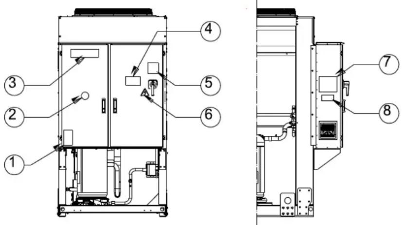
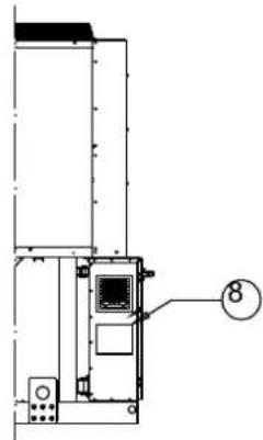
Figure 1 - Description of the labels applied to the electrical panel
Label Identification
| 1 – Non flammable gas symbol | 5 – Cable tightening warning |
| 2 – Gas type | 6 – Electrical hazard symbol |
| 3 – Manufacturer’s logo | 7 – Lifting instructions |
| 4 – Hazardous Voltage warning | 8 – Unit nameplate data |

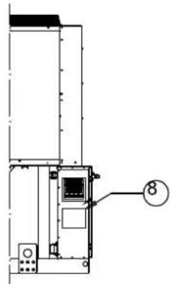
Label Identification
| 1 – Non flammable gas symbol | 5 – Cable tightening warning |
| 2 – Gas type | 6 – Hazardous Voltage warning |
| 3 – Unit nameplate data | 7 – Electrical hazard symbol |
| 4 – Manufacturer’s logo | 8 – Lifting instructions |
Figure 2 - Operating limits
line
| Reference Point | ELWT (°C) | CQT (°C) | | --------------- | --------- | -------- | | Ref. A | -13 | 45 | | Ref. B | 12 | -10 | | Ref. C | 17 | -5 | | Ref. D | -8 | 30 | | Ref. E | -8 | -20 |Note
The above graphic represents a guidelines about the operating limits of the range. Please refer to Chiller Selection Software (CSS) for real operating limits working conditions for each size.
Legend
CIAT = Condenser Inlet Air Temperature (°C)
ELWT = Evaporator Leaving Water Temperature (°C)
A = Operation with Glycol (below 4°C Evap LWT)
B = Fan speed modulation or Speedtroll required (below 10°C Condens. Air Temp.)
C = Fan speed modulation or Speedtroll required (below 10°C and up to -10°C Condens. Air Temp.)*
*Only referred to units with 4-5-6 fans
D = In this area units can work at partial load
E = In this area the unit minimum capacity might be higher than value shown in Technical Specification table
F = Standard Efficiency (standard sound)
G = High Efficiency (standard sound)
Safety
The unit must be firmly secured to the soil.
It is essential to observe the following instructions:
- The unit can only be lifted using the lifting points marked in yellow fixed to its base.
- It is forbidden to access the electrical components without having opened the unit main switch and switched off the power supply.
- It is forbidden to access the electrical components without using an insulating platform. Do not access the electrical components if water and/or moisture are present.
- Sharp edges and the surface of the condenser section could cause injury. Avoid direct contact and use adequate protection device
- Switch off power supply, by opening the main switch, before servicing the cooling fans and/or compressors. Failure to observe this rule could result in serious personal injury.
- Do not introduce solid objects into the water pipes while the unit is connected to the system.
- A mechanical filter must be installed on the water pipe connected to the heat exchanger inlet.
- The unit is supplied with safety valves, that are installed both on the high-pressure and on the low-pressure sides of the refrigerant circuit.
It is absolutely forbidden to remove all protections of moving parts.
In case of sudden stop of the unit, follow the instructions on the Control Panel Operating Manual which is part of the onboard documentation delivered to the end user.
It is strongly recommended to perform installation and maintenance with other people. In case of accidental injury or unease, it is necessary to:
- keep calm
- press the alarm button if present in the installation site
- move the injured person in a warm place far from the unit and in rest position
- contact immediately emergency rescue personnel of the building or the Health Emergency Service
- wait without leaving the injured person alone until the rescue operators come
- give all necessary information to the rescue operators

Avoid installing the chiller in areas that could be dangerous during maintenance operations, such as platforms without parapets or railings or areas not complying with the clearance requirements around the chiller.
Noise
The unit is a source of noise mainly due to rotation of compressors and fans.
The noise level for each model size is listed in sales documentation.
If the unit is correctly installed, operated and manteined the noise emission level do not require any special protection device to operate continuously close to the unit without any risk. In case of installation with special noise requirements it could be necessary to install additional sound attenuation devices.
Moving and lifting
Avoid bumping and/or jolting during loading/unloading unit from the truck and moving it. Do not push or pull the unit from any part other than the base frame. Secure the unit inside the truck to prevent it from moving and causing damages. Do not allow any part of the unit to fall during transportation or loading/unloading.
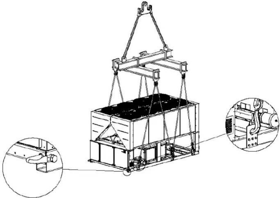
All units are supplied with the lifting points marked in yellow. Only these points may be used for lifting the unit, as shown in the following Figure 3.

Both the lifting ropes and the spacing bars must be strong enough to support the unit safely. Please check the unit's weight on the unit nameplate.
The unit must be lifted with the utmost attention and care following lifting label instructions; lift unit very slowly, keeping it perfectly level.
Positioning and assembly
All units are designed for installation outdoors, either on balconies or on the ground, provided that the installation area is free of obstacles that could reduce air flow to the condensers coil.
The unit must be installed on a robust and perfectly level foundation; should the unit be installed on balconies or roofs, it might be necessary to use weight distribution beams.
Figure 3 - Lifting the unit
5 fans version
natural_image
Technical line drawing of a mechanical lifting device with two inset views showing internal components (no text or symbols)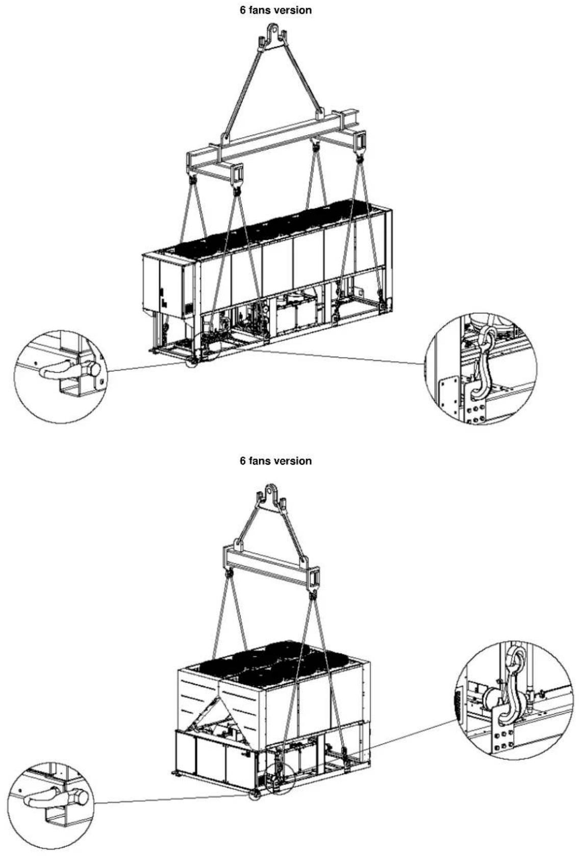
10-12 fans version
(The drawing shows only the 8 fans version. For the 10-12 fans version the lifting mode is the same)
natural_image
Technical line drawing of a mechanical lifting device with two inset views showing internal components (no text or symbols)For installation on the ground, a strong concrete base, at least 250 mm thickness and wider than the unit must be provided.
This base must be able to support the weight of the unit.
If the unit is installed in places that are easily accessible to people and animals, it is advisable to install protection grids for the condenser and compressor sections.
To ensure best performance on the installation site, the following precautions and instructions must be followed:
- Avoid air flow recirculation.
- Make sure that there are no obstacles to hamper air flow.
- Make sure to provide a strong and solid foundation to reduce noise and vibrations.
- Avoid installation in particularly dusty environments, in order to reduce soiling of condensers coils.
- The water in the system must be particularly clean and all traces of oil and rust must be removed. A mechanical water filter must be installed on the unit's inlet piping.
Minimum space requirements
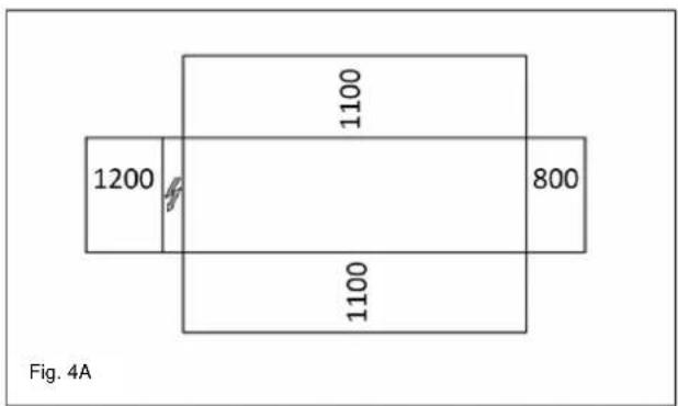
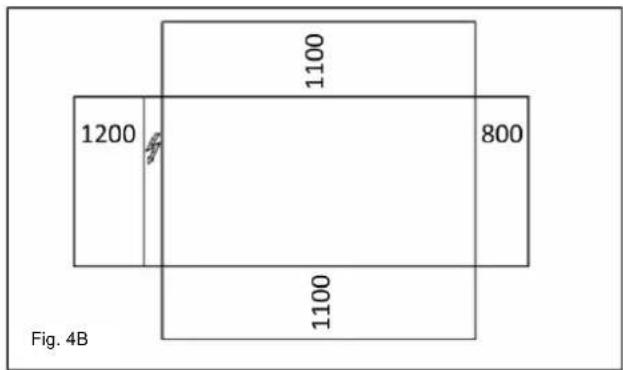
It is fundamental to respect minimum distances on all units in order to ensure optimum ventilation to the condenser coils.
When deciding where to position the unit and to ensure a proper air flow, the following factors must be taken into consideration:
- avoid any warm air recirculation
- avoid insufficient air supply to the air-cooled condenser.
Both these conditions can cause an increase of condensing pressure, which leads to a reduction in energy efficiency and refrigerating capacity.
Any side of the unit must be accessible for post-installation maintenance operations. Figure 4 shows the minimum space required.
Vertical air discharge must not be obstructed.
If the unit is surrounded by walls or obstacles of the same height as the unit, this must be installed at a distance no lower than (see Figure 4C or 4D). If these obstacles are higher, the unit must be installed at a distance no lower (see Figure 4E or 4F).
Should the unit be installed without observing the recommended minimum distances from walls and/or vertical obstacles, there could be a combination of warm air
recirculation and/or insufficient supply to the air-cooled condenser which could cause a reduction of capacity and efficiency.
In any case, the microprocessor will allow the unit to adapt itself to new operating conditions and deliver the maximum available capacity under any given circumstances, even if the lateral distance is lower than recommended, unless the operating conditions should affect personnel safety or unit reliability.
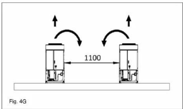
When two or more units are positioned side by side, a distance of at least (see Figure 4G or 4H) between condenser banks is recommended.
For further solutions, please consult manufacturer representative.
Sound protection
When sound levels require special control, great care must be exercised to isolate the unit from its base by appropriately applying anti-vibration elements (supplied as an option).
Flexible joints must be installed on the water connections, as well.
Water piping
Piping must be designed with the lowest number of elbows and the lowest number of vertical changes of direction. In this way, installation costs are reduced considerably and system performance is improved.
The water system must have:
- Anti-vibration mountings in order to reduce transmission of vibrations to the structures.
- Isolating valves to isolate the unit from the water system during service.
- Manual or automatic air venting device at the system's highest point.; drain device at the system's lowest point.
- Neither the evaporator nor the heat recovery device must be positioned at the system's highest point.
- A suitable device that can maintain the water system under pressure (expansion tank, etc.).
- Water temperature and pressure indicators to assist the operator during service and maintenance.
Figure 4 - Minimum clearance requirements

- A filter or device that can remove particles from the fluid. The use of a filter extends the life of the evaporator and pump and helps to keep the water system in a better condition.
- Evaporator has an electrical resistance with a thermostat that ensures protection against water freezing at ambient temperatures as low as -25^ C. All the other water piping/devices outside the unit must therefore be protected against freezing.
-
The heat recovery device must be emptied of water during the winter season, unless an ethylene glycol mixture in appropriate percentage is added to the water circuit.
-
If case of unit substitution, the entire water system must be emptied and cleaned before the new unit is installed. Regular tests and proper chemical treatment of water are recommended before starting up the new unit.
- In the event that glycol is added to the water system as anti-freeze protection, pay attention to the fact that suction pressure will be lower, the unit's performance will be lower and water pressure drops will be greater. All unit-protection systems, such as anti-freeze, and low-pressure protection will need to be readjusted.
- Before insulating water piping, check that there are no leaks.
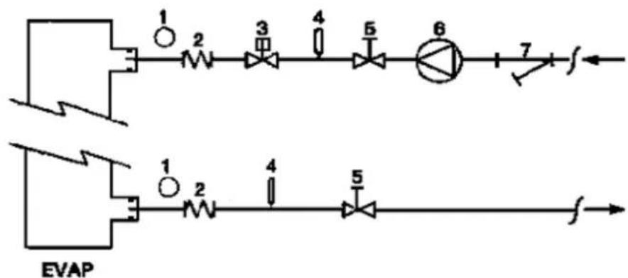
Figure 5 - Water piping connection for evaporator
flowchart
graph TD
    A["Component 1"] --> B["Component 2"]
    B --> C["Component 3"]
    C --> D["Component 4"]
    D --> E["Component 5"]
    E --> F["Component 6"]
    F --> G["Component 7"]
    G --> H["Output f"]
    I["Component 1"] --> J["Component 2"]
    J --> K["Component 3"]
    K --> L["Component 4"]
    L --> M["Component 5"]
    M --> N["Component 6"]
    N --> O["Output f"]
    P["External Component"] --> Q["External Component"]
- Pressure Gauge
- Flexible connector
- Flow switch
-
Temperature probe
-
Isolation Valve
- Pump
- Filter
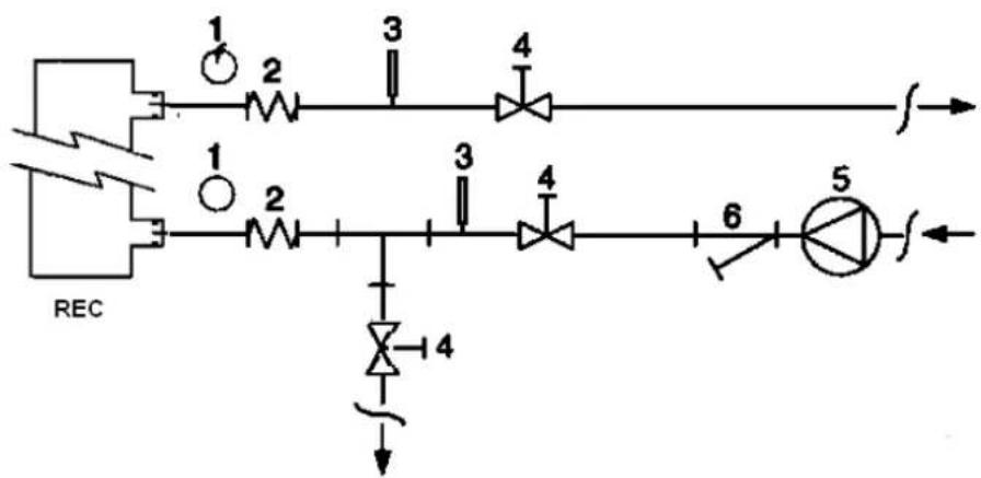
Figure 6 - Water piping connection for heat recovery exchangers
flowchart
graph TD
    A["REC"] --> B["1"]
    A --> C["2"]
    B --> D["3"]
    C --> E["4"]
    D --> F["5"]
    E --> G["6"]
    G --> H["7"]
    H --> I["8"]
    I --> J["9"]
    J --> K["10"]
    K --> L["11"]
    L --> M["12"]
    M --> N["13"]
    N --> O["14"]
    O --> P["15"]
    P --> Q["16"]
    Q --> R["17"]
    R --> S["18"]
    S --> T["19"]
    T --> U["20"]
- Pressure Gauge
- Flexible connector
-
Temperature probe
-
Isolation Valve
- Pump
- Filter
Water treatment
Before putting the unit into operation, clean the water circuit. Dirt, scales, corrosion debris and other material can accumulate inside the heat exchanger and reduce its heat exchanging capacity. Pressure drop can increase as well, thus reducing water flow. Proper water treatment therefore reduces
the risk of corrosion, erosion, scaling, etc. The most appropriate water treatment must be determined locally, according to the type of system and water characteristics. The manufacturer is not responsible for damage to or malfunctioning of equipment caused by failure to treat water or by improperly treated water.
Table 1 - Acceptable water quality limits
| pH (25°C) | 6,8÷8,0 | Total Hardness (mg CaCO_3 /l) | < 200 | |
| Electrical conductivity μS/cm (25°C) | <800 | Iron (mg Fe / l) | < 1.0 | |
| Chloride ion (mg Cl^- /l) | <200 | Sulphide ion (mg S^2^- /l) | None | |
| Sulphate ion (mg SO_4^2- /l) | <200 | Ammonium ion (mg NH_4^+ /l) | < 1.0 | |
| Alkalinity (mg CaCO_3 /l) | <100 | Silica (mg SiO_2 /l) | < 50 |
Evaporator and recovery exchangers anti-freeze protection
All evaporators are supplied with a thermostatically controlled anti-freeze electrical resistance, which provides adequate anti-freeze protection at temperatures as low as -25^ . However, unless the heat exchangers are completely empty and cleaned with anti-freeze solution, additional methods should also be used against freezing.
Two or more of below protection methods should be considered when designing the system as a whole:
- Continuous water flow circulation inside piping and exchangers
– Addition of an appropriate amount of glycol inside the water circuit
– Additional heat insulation and heating of exposed piping - Emptying and cleaning of the heat exchanger during the winter season
It is the responsibility of the installer and/or of local maintenance personnel to ensure that described anti-freeze methods are used. Make sure that appropriate anti-freeze protection is maintained at all times. Failing to follow the instructions above could result in unit damage. Damage caused by freezing is not covered by the warranty.
Installing the flow switch
To ensure sufficient water flow through the evaporator, it is essential that a flow switch be installed on the water circuit. The flow switch can be installed either on the inlet or outlet water piping. The purpose of the flow switch is to stop the unit in the event of interrupted water flow, thus protecting the evaporator from freezing.
The manufacturer offers, as optional, a flow switch that has been selected for this purpose.
This paddle-type flow switch is suitable for heavy-duty outdoor applications (IP67) and pipe diameters in the range of 1" to 6". The flow switch is provided with a clean contact which must be electrically connected to terminals shown in the wiring diagram.
Flow switch has to be tune to intervene when the evaporator water flow is lower than 50% of nominal flow rate.
Heat recovery
Units may be optionally equipped with heat recovery system. This system in made by a water cooled heat exchanger located on the compressors discharge pipe and a dedicated management of condensing pressure.
To guarantee compressor operation within its envelope, units with heat recovery cannot operate with water temperature of the heat recovery water lower than 28^ C.
It is a responsibility of plant designer and chiller installer to guarantee the respect of this value (e.g. using recirculating bypass valve)
Electrical Installation
General specifications

All electrical connections to the unit must be carried out in compliance with laws and regulations in force.
All installation, management and maintenance activities must be carried out by qualified personnel. Refer to the specific wiring diagram for the unit you have bought. Should the wiring diagram not be on the unit or should it have been lost, please contact your manufacturer representative, who will send you a copy. In case of discrepancy between wiring diagram and electrical panel/cables, please contact the manufacturer representative.
Only use copper conductors. Failure to use copper conductors could result in overheating or corrosion at connection points and could damage the unit.
To avoid interference, all control wires must be connected separately from the power cables. Use different electrical passage ducts for this purpose.
Before servicing the unit in any way, open the general disconnecting switch on the unit's main power supply.
When the unit is off but the disconnecting switch is in the closed position, unused circuits are live, as well.
Never open the terminal board box of the compressors before having opened the unit's general disconnecting switch.
Contemporaneity of single-phase and three-phase loads and unbalance between phases could cause leakages towards ground up to 150mA, during the normal operation of the units of the series.
If the unit includes devices that cause superior harmonics (like VFD and phase cut), the leakage towards ground could increase to very higher values (about 2 Ampere).
The protections for the power supply system have to be designed according to the above mentioned values.
Operation
Operator's responsibilities
It is essential that the operator is appropriately trained and becomes familiar with the system before operating the unit. In addition to reading this manual, the operator must study the microprocessor operating manual and the wiring diagram in order to understand start-up sequence, operation, shutdown sequence and operation of all the safety devices.
During the unit's initial start-up phase, a technician authorized by the manufacturer is available to answer any questions and to give instructions as to the correct operating procedures.
The operator must keep a record of operating data for every installed unit. Another record should also be kept of all the periodical maintenance and servicing activities.
If the operator notes abnormal or unusual operating conditions, he is advised to consult the technical service authorized by the manufacturer.

If all power to the unit is turned off, the compressors will become inoperable. Once power is resumed to the he compressor and oil separator heaters must beized a minimum of 12 hours before attempting to start the
Failure to do so can damage the compressors due to excessive accumulation of liquid in the compressor.
Routine maintenance
Minimum maintenance activities are listed in Table 2
Service and limited warranty
All units are factory-tested and guaranteed for 12 months as of the first start-up or 18 months as of delivery.
These units have been developed and constructed according to high quality standards ensuring years of failure-free operation. It is important, however, to ensure proper and periodical maintenance in accordance with all the procedures listed in this manual and with good practice of machines maintenance.
We strongly advise stipulating a maintenance contract with a service authorized by the manufacturer in order to ensure efficient and problem-free service, thanks to the expertise and experience of our personnel.
It must also be taken into consideration that the unit requires maintenance also during the warranty period.
It must be borne in mind that operating the unit in an inappropriate manner, beyond its operating limits or not performing proper maintenance according to this manual can void the warranty.
Observe the following points in particular, in order to conform to warranty limits:
- The unit cannot function beyond the specified limits
- The electrical power supply must be within the voltage limits and without voltage harmonics or sudden changes.
- The three-phase power supply must not have un balance between phases exceeding 3%. The unit must stay turned off until the electrical problem has been solved.
- No safety device, either mechanical, electrical or electronic must be disabled or overridden.
-
The water used for filling the water circuit must be clean and suitably treated. A mechanical filter must be installed at the point closest to the evaporator inlet.
-
Unless there is a specific agreement at the time of ordering, the evaporator water flow rate must never be above 120% and below 80% of the nominal flow rate.
For chillers belonging to this category, some local regulations require a periodic inspection by an authorized agency. Please check with your local requirements.
Periodic obligatory checks and starting up of appliances under pressure
The units are included in category III of the classification established by the European Directive PED 2014/68/EU.
Table 2 - Routine maintenance programme
| List of Activities | Weekly | Monthly (Note 1) | Yearly/Seasonal (Note 2) |
| General: | |||
| Reading of operating data (Note 3) | X | ||
| Visual inspection of unit for any damage and/or loosening | X | ||
| Verification of thermal insulation integrity | X | ||
| Clean and paint where necessary | X | ||
| Analysis of water (5) | X | ||
| Check of flow switch operation | X | ||
| Electrical: | |||
| Verification of control sequence | X | ||
| Verify contactor wear – Replace if necessary | X | ||
| Verify that all electrical terminals are tight – Tighten if necessary | X | ||
| Clean inside the electrical control board | X | ||
| Visual inspection of components for any signs of overheating | X | ||
| Verify operation of compressor and electrical resistance | X | ||
| Measure compressor motor insulation using the Megger | X | ||
| Refrigeration circuit: | |||
| Check for any refrigerant leakage | X | ||
| Verify refrigerant flow using the liquid sight glass – Sight glass full | X | ||
| Verify filter dryer pressure drop | X | ||
| Analyse compressor vibrations | X | ||
| Analyse compressor oil acidity (Note 6) | X | ||
| Condenser section: | |||
| Clean condenser banks (Note 4) | X | ||
| Verify that fans are well tightened | X | ||
| Verify condenser bank fins – Comb if necessary | X |
Notes:
1. Monthly activities include all the weekly ones.
2. The annual (or early season) activities include all weekly and monthly activities.
3. Unit operating values should be read on a daily basis thus keeping high observation standards.
4. In environments with a high concentration of air-borne particles, it might be necessary to clean the condenser bank more often.
5. Check for any dissolved metals.
6. TAN (Total Acid Number) : ≤ 0,10 : No action
Between 0.10 and 0.19 : Replace anti-acid filters and re-check after 1000 running hours. Continue to replace filters
until the TAN is lower than 0.10.
0,19 : Replace oil, oil filter and filter dryer. Verify at regular intervals.
Important information regarding the refrigerant used
This product contains fluorinated greenhouse gases. Do not vent gases into the atmosphere.
Refrigerant type: R410A
GWP(1) value: 2087,5
(1)GWP = Global Warming Potential
The refrigerant quantity necessary for standard operation is indicated on the unit name plate.
Real refrigerant quantity charged in the unit is listed on a silver sticker inside the electrical panel.
Periodical inspections for refrigerant leaks may be required depending on European or local legislation.
Please contact your local dealer for more information.
Factory and Field charged units instructions
(Important information regarding the refrigerant used)
The refrigerant system will be charged with fluorinated greenhouse gases.
Do not vent gases into the atmosphere.
1 Fill in with indelible ink the refrigerant charge label supplied with the product as following instructions:
- the refrigerant charge for each circuit (1; 2; 3)
- the total refrigerant charge (1 + 2 + 3)
- calculate the greenhouse gas emission with the following formula:
GWP value of the refrigerant x Total refrigerant charge (in kg) / 1000
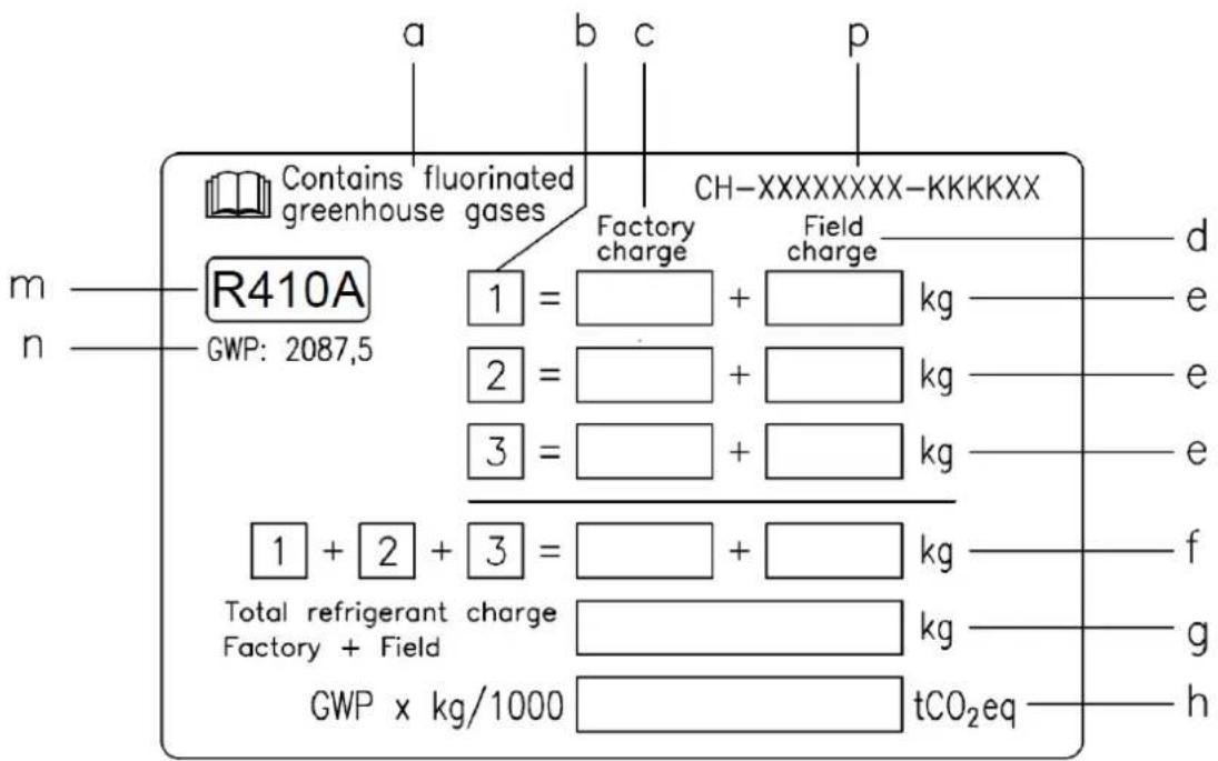
a Contains fluorinated greenhouse gases
b Circuit number
c Factory charge
d Field charge
e Refrigerant charge for each circuit (according to the number of circuits)
f Total refrigerant charge
g Total refrigerant charge (Factory + Field)
h Greenhouse gas emission of the total refrigerant charge expressed as tonnes of CO2 equivalent
m Refrigerant type
n GWP = Global Warming Potential
p Unit serial number
2 The filled out label must be adhered inside the electrical panel.
Periodical inspections for refrigerant leaks may be required depending on European or local legislation. Please contact your local dealer for more information.
NOTICE
In Europe, the greenhouse gas emission of the total refrigerant charge in the system (expressed as tonnes CO _2 equivalent) is used to determine the maintenance intervals.
Follow the applicable legislation.
Formula to calculate the greenhouse gas emission:
GWP value of the refrigerant x Total refrigerant charge (in kg) / 1000
Use the GWP value mentioned on the greenhouse gases label. This GWP value is
based on the 4th IPCC Assessment Report. The GWP value mentioned in the manual might be outdated (i.e. based on the 3rd IPCC Assessment Report)
Disposal
The unit is made of metal, plastic and electronic parts. All these parts must be disposed of in accordance with the local regulations in terms of disposal.
Lead batteries must be collected and sent to specific refuse collection centres.
Oil must be collected and sent to specific refuse collection centres.
This manual is a technical aid and does not represent a binding offer. The content cannot be held as explicitly or implicitly guaranteed as complete, precise or reliable. All data and specifications contained herein may be modified without notice. The data communicated at the moment of the order shall hold firm. The manufacturer shall assume no liability whatsoever for any direct or indirect damage, in the widest sense of the term, ensuing from or connected with the use and/or interpretation of this manual.
We reserve the right to make changes in design and construction at any time without notice, thus the cover picture is not binding.

Schilder-Anordnung
Schilder-Anordnung
line
| Reference | Minimum ELWT (°C) | | --------- | ----------------- | | Ref. A | -13 | | Ref. B | 12 | | Ref. C | 17 | | Ref. D | -8 |natural_image
Technical line drawing of a mechanical lifting device with two inset views showing internal components (no text or symbols)(1)GWP = Global Warming Potential
n GWP = Global warming potential (Treibhauspotential)
line
| Reference | Minimum ELWT (°C) | | --------- | ----------------- | | Ref. A | -13 | | Ref. B | 12 | | Ref. C | 16 | | Ref. D | -13 | | Ref. E | -8 |Remarque
natural_image
Technical line drawing of a mechanical device suspended by crane, with two inset views showing internal components (no text or symbols)natural_image
Technical line drawing of a mechanical lifting device with two circular insets showing close-ups of components (no text or symbols)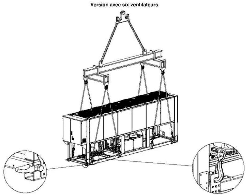
natural_image
Technical line drawing of a mechanical lifting device with three circular insets showing close-ups of components (no text or symbols)Identificatie Etiket

Identificatie Etiket
line
| Reference | ELWT (°C) | QAT (°C) | | --------- | --------- | -------- | | Ref. A | -13 | 30 | | Ref. B | 12 | 45 | | Ref. C | 17 | 40 | | Ref. D | -13 | 30 | | Ref. E | -8 | -20 |natural_image
Technical line drawing of a mechanical lifting device with two circular insets showing close-ups of components (no text or symbols)(1)GWP = Global Warming Potential

line
| Reference | QAT (°C) | ELWT (°C) | | --------- | -------- | --------- | | Ref. A | 45 | -13 | | Ref. B | -10 | 12 | | Ref. C | -5 | 17 | | Ref. D | 30 | -13 | | Ref. E | -20 | -8 |natural_image
Technical line drawing of a mechanical device suspended by crane, with two inset views showing internal components (no text or symbols)natural_image
Technical line drawing of a mechanical lifting device with two inset views showing internal components (no text or symbols)
natural_image
Technical line drawing of a mechanical lifting device with two inset views showing internal components (no text or symbols)(1)GWP = Global Warming Potential

line
| Reference | ELWT (°C) | CLAT (°C) | | --------- | --------- | --------- | | Ref. A | -13 | 30 | | Ref. A | -8 | 35 | | Ref. A | -3 | 40 | | Ref. A | 2 | 45 | | Ref. B | 12 | -10 | | Ref. B | 17 | -15 | | Ref. C | 17 | 40 | | Ref. D | -13 | 50 | | Ref. E | -13 | -20 |natural_image
Technical line drawing of a mechanical device suspended by crane, with two inset views showing internal components (no text or symbols)natural_image
Technical line drawing of a mechanical lifting device with two inset views showing internal components (no text or symbols)
natural_image
Technical line drawing of a mechanical lifting device with two inset views showing internal components (no text or symbols)

line
| Label | ELWT (°C) | CIAT (°C) | | :--- | :--- | :--- | | Ref. D | -13 | 30 | | Ref. A | -8 | 35 | | Ref. E | -8 | -5 | | Ref. B | 12 | -15 | | Ref. C | 17 | 40 | -13°C minimum ELWT with Ethyleneglycol -10°C minimum ELWT with Propylene glycolnatural_image
Technical line drawing of a mechanical lifting device with two inset views showing internal components (no text or symbols)other
| Dimension | Value | |---|---| | Top Section | 1200 | | Bottom Section | 800 | | Middle Section | 1100 | | Top Section (labeled) | 1100 | | Bottom Section (labeled) | 1100 | | Intersection Point | g (small symbol) |

line
| Reference | Minimum ELWT (°C) | Minimum OAT (°C) | | --------- | ----------------- | ---------------- | | Ref. A | -13 | 45 | | Ref. B | 12 | -15 | | Ref. C | 17 | -10 | | Ref. D | -8 | 50 | | Ref. E | -13 | -20 |natural_image
Technical line drawing of a mechanical lifting device with two inset views showing internal components (no text or symbols)Определение ярлыков
Определение ярлыков
line
| Reference Line | ELWT (°C) | QAT (°C) | | -------------- | --------- | -------- | | Ref. A | -13 | 30 | | Ref. A | -6 | 35 | | Ref. A | 2 | 45 | | Ref. B | 12 | -10 | | Ref. C | 17 | -10 |natural_image
Technical line drawing of a mechanical lifting device with two inset views showing internal components (no text or symbols)Skyldkod
| 1 – Ej brandfarlig gas symbolen | 5 – Kabeln åtdragning varning |
| 2 – Gastyp | 6 – Elektrisk farosymbol |
| 3 – Tillverkarens logotyp | 7 – Lyftinstruktioner |
| 4 – Livsfarlig spänning varning | 8 - Enhet märkskylten |


Skyldkod
line
| Reference | Minimum ELWT (°C) | | --------- | ----------------- | | Ref. A | -13 | | Ref. A | -10 | | Ref. B | 12 | | Ref. C | 16 |natural_image
Technical line drawing of a mechanical lifting device with two circular insets showing close-ups of components (no text or symbols)
line
| Reference | Minimum ELWT (°C) | | --------- | ----------------- | | Ref. A | -13 | | Ref. B | 12 | | Ref. C | 17 | | Ref. D | -8 |natural_image
Technical line drawing of a mechanical device suspended by crane, with two inset views showing internal components (no text or symbols)Modell med 5 vifter

natural_image
Technical line drawing of a mechanical lifting device with two inset views showing internal components (no text or symbols)
natural_image
Technical line drawing of a mechanical lifting device with two inset views showing internal components (no text or symbols)(1)GWP = Global Warming Potential
(Global potensiell oppvarming)
a Inneholder fluorholdige klimagasser
b Kretsnummer
c Fabrikkfylt
d Feltfylt

line
| Reference | ELWT (°C) | QAT (°C) | | --------- | --------- | -------- | | Ref. A | -13 | 45 | | Ref. B | 12 | -10 | | Ref. C | 17 | 40 | | Ref. D | -13 | 30 | | Ref. E | -8 | -10 |natural_image
Technical line drawing of a mechanical device suspended by crane, with two inset views showing internal components (no text or symbols)natural_image
Technical line drawing of a mechanical lifting device with two inset views showing internal components (no text or symbols)
natural_image
Technical line drawing of a mechanical lifting device with two inset views showing internal components (no text or symbols)other
| Dimension | Value | |---|---| | Top Section | 1200 | | Bottom Section | 800 | | Left Section | 1100 | | Right Section | 1100 | Kuva 4A
(1)GWP = Global Warming Potential

line
| Reference | Minimum ELWT (°C) | Minimum OAT (°C) | | --------- | ------------------ | ----------------- | | Ref. A | -13 | 45 | | Ref. B | 12 | 45 | | Ref. C | 17 | 40 | | Ref. D | -8 | 30 | | Ref. E | -8 | -20 |natural_image
Technical line drawing of a mechanical device suspended by crane, with two inset views showing internal components (no text or symbols)natural_image
Technical line drawing of a mechanical lifting device with two inset views showing internal components (no text or symbols)
natural_image
Technical line drawing of a mechanical lifting device with two circular insets showing close-ups of components (no text or symbols)Identifikace štítku
Identifikace štítku
line
| Reference | Minimum ELWT (°C) | | --------- | ----------------- | | Ref. A | -13 | | Ref. B | 12 | | Ref. C | 17 | | Ref. D | -8 |natural_image
Technical line drawing of a crane lifting a rectangular container, with two circular insets showing close-ups of mechanical components (no text or symbols)
natural_image
Technical line drawing of an electrical enclosure or enclosure with a labeled component (no text or symbols present)line
| Reference Line | Minimum ELWT (°C) | | -------------- | ----------------- | | Ref. A | -13 | | Ref. B | 12 | | Ref. C | 17 | | Ref. D | -8 |Napomena
Gore prikazani grafikon predstavlja vodič o operativnim ograničenjima. Molimo Vas konzultirajte Software za izbor Rashladnog Uređaja (CSS) da biste vidjeli koja su ograničenja za svaku veličinu.
Tumač
CIAT = Kondenzator Ulazna Temperatura Zraka (°C)
ELWT = Isparivač Izlazna Temperatura Vode (°C)
A = Operacije s Glikolom (ispod 4°C Ispar LWT)
B = Brzina ventilacije moduliranja ili potrebni Speedtroll (ispod 10°C Kondenz. Temp.Zraka)
C = Brzina ventilacije moduliranja ili potrebni Speedtroll (ispod 10°C Kondenz. Temp.Zraka)*
*Odnosi se samo na uređaje s 4-5-6 ventilatora
natural_image
Technical line drawing of a mechanical lifting device with two inset views showing internal components (no text or symbols)Kada se radi o instalaciji na tlu, jakoj betonskoj podlozi, najmanje 250 mm debljine i širine treba ostaviti oko uređaja.
(1)GWP = Global Warming
Potential (Potencijal Globalnog
Zatopljenja)
Količina potrebnog rashladnog sredstva potrebnog za standardne operacije se navodi na natpisnoj pločici uređaja.
Stvarna količina unesenog rashladnog sredstva u uređaj se navodi na srebrenoj naljepnici u unutrašnjosti električne ploče.
Periodična inspekcija curenja rashladnog sredstva može biti potrebna s obzirom na Europske ili lokalne propise.
Molimo Vas da kontaktirate vašeg lokalnog zastupnika radi dodatnih informacija.
Upute o tvorničkom punjenju jedinica i punjenju na terenu
a Sadrži fluorirane stakleničke plinove
b Broj kruga
c Tvorničko punjenje
d Punjenje na terenu

line
| Reference Line | ElWT (°C) Range | Clat (°C) Range | | -------------- | ---------------- | ---------------- | | Ref. A | -13 | 20 | | Ref. B | 12 | -10 | | Ref. C | 17 | -10 | | Ref. D | -13 | 30 | | Ref. E | -8 | -20 |Megjegyzés
natural_image
Technical line drawing of a mechanical lifting device with two inset views showing internal components (no text or symbols)
line
| Reference | Minimum ELWT (°C) | Minimum ILWT (°C) | | --------- | ----------------- | ----------------- | | Ref. A | -13 | -3 | | Ref. B | 12 | 12 | | Ref. C | 17 | 17 | | Ref. D | -13 | -13 | | Ref. E | -3 | -3 |natural_image
Technical line drawing of a mechanical device suspended by crane, with two circular insets showing close-ups of internal components (no text or symbols)natural_image
Technical line drawing of a mechanical lifting device with two inset views showing internal components (no text or symbols)
natural_image
Technical line drawing of a mechanical lifting device with two circular insets showing close-ups of components (no text or symbols)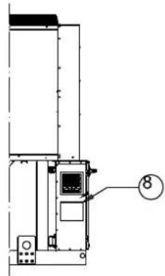
line
| Point | ELWT (°C) | QAT (°C) | |-------|-----------|----------| | Ref. A | -8 | 20 | | Ref. B | 12 | -15 | | Ref. C | 17 | -10 | | Ref. D | -13 | 30 | | Ref. E | -8 | -5 |natural_image
Technical line drawing of a mechanical lifting device with two inset views showing internal components (no text or symbols)a Vsebuje fluorirane toplogredne pline
b Številka kroga


natural_image
Technical line drawing of an electrical enclosure or enclosure with a labeled component (no text or symbols present)line
| Reference | Minimum ELWT (°C) | | --------- | ----------------- | | Ref. A | -13 | | Ref. A | -10 | | Ref. B | 12 | | Ref. C | 17 |natural_image
Technical line drawing of a mechanical device suspended by crane, with two inset views showing internal components (no text or symbols)natural_image
Technical line drawing of a mechanical lifting device with two circular insets showing close-ups of components (no text or symbols)natural_image
Technical line drawing of a mechanical lifting device with two inset views showing internal components (no text or symbols)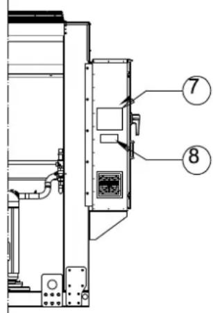
Opis oznak

Opis oznak
line
| Reference | ELWT (°C) | COT (°C) | | --------- | --------- | -------- | | Ref. A | -13 | 45 | | Ref. B | 12 | -15 | | Ref. C | 17 | -15 | | Ref. D | -13 | 30 | | Ref. E | -8 | -20 |natural_image
Technical line drawing of a mechanical lifting device with crane and internal components, shown in two circular insets (no text or symbols)other
| Section | Value | |---|---| | Top Section | 1200 | | Bottom Section | 800 | | Middle Section | 1100 | | Top Section (Left) | 1100 | | Bottom Section (Right) | 1100 | Slika 4A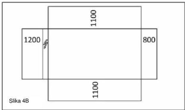
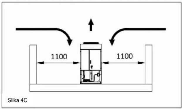
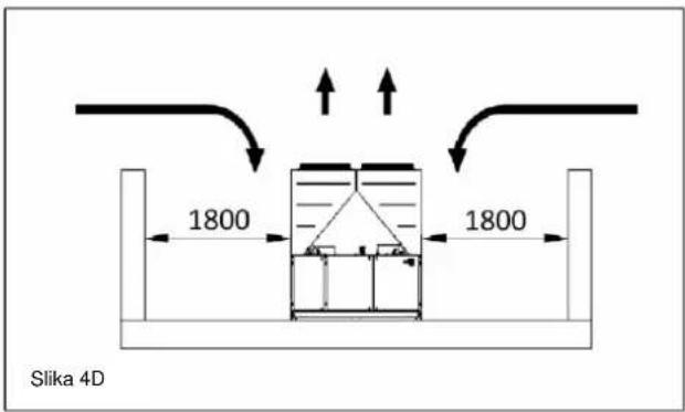
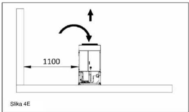

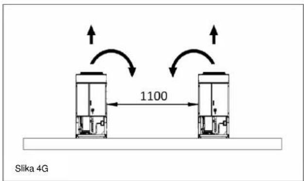
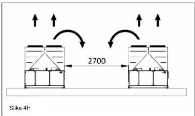
(1)GWP = Global Warming Potential
(potencial segrevanja ozračja)
The present publication is drawn up by of information only and does not constitute an offer binding upon Daikin Applied Europe S.p.A.. Daikin Applied Europe S.p.A. has compiled the content of this publication to the best of its knowledge. No express or implied warranty is given for the completeness, accuracy, reliability or fitness for particular purpose of its content, and the products and services presented therein. Specification are subject to change without prior notice. Refer to the data communicated at the time of the order. Daikin Applied Europe S.p.A. explicitly rejects any liability for any direct or indirect damage, in the broadest sense, arising from or related to the use and/or interpretation of this publication. All content is copyrighted by Daikin Applied Europe S.p.A..
DAIKIN APPLIED EUROPE S.p.A.
- Installation, Operation and Maintenance Manual
- D-EIMAC00808-16EU
- Air cooled scroll chiller
- EWAQ\~E- / EWAQ\~F-
- Description
- General Information
- CONSIDERED ESSENTIAL DOCUMENTS OF THIS MANUAL
- Receiving the unit
- Operating limits
- Storing
- Operation
- Legend
- Safety
- It is absolutely forbidden to remove all protections of moving parts.
- Noise
- Moving and lifting
- Positioning and assembly
- Minimum space requirements
- Sound protection
- Water piping
- Water treatment
- Evaporator and recovery exchangers anti-freeze protection
- Installing the flow switch
- Heat recovery
- Electrical Installation
- General specifications
- Operator's responsibilities
- Routine maintenance
- Service and limited warranty
- Periodic obligatory checks and starting up of appliances under pressure
- Important information regarding the refrigerant used
- Factory and Field charged units instructions
- NOTICE
- Formula to calculate the greenhouse gas emission:
- Disposal
- Remarque
- Upute o tvorničkom punjenju jedinica i punjenju na terenu
- Megjegyzés
Brand : DAIKIN
Model : EWAQ-E-XR
Category : Computer cooling system