
IS 3180 KNX - Alarm system STEINEL - Free user manual and instructions
Find the device manual for free IS 3180 KNX STEINEL in PDF.

User questions about IS 3180 KNX STEINEL
0 question about this device. Answer the ones you know or ask your own.
Ask a new question about this device
Download the instructions for your Alarm system in PDF format for free! Find your manual IS 3180 KNX - STEINEL and take your electronic device back in hand. On this page are published all the documents necessary for the use of your device. IS 3180 KNX by STEINEL.
USER MANUAL IS 3180 KNX STEINEL
natural_image
World map silhouette in grayscale, showing continents and oceans without any text or labelsContact
www.steinel.de/contact

110061114 12/2019_A Technische Änderungen vorbehalten. / Subject to technical modification without notice.

GB ..... 22 Follow written instructions!
natural_image
Three technical line drawings of mechanical components or parts, no text or symbols present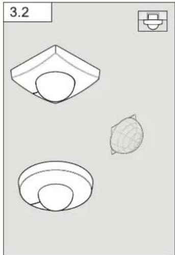
natural_image
Three technical line drawings of a mechanical component or housing, showing front, top, and side views (no text or symbols)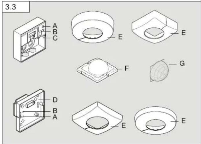
6
7
8
9
DE
- Please read carefully and keep in a safe place.
- Undercopyright.
Reproduction either in whole or in part only with our consent. - Subject to change in the interest of technical progress.
Symbols

Hazard warning!

Reference to other information in the document.
2. General safety precautions

Disconnect the power supply before attempting any work on the sensor.
- This product must only be installed by a qualified electrician in accordance with national wiring regulations as defined in VDE 08 29 (DIN EN 5000 90).
- Installed improperly, low-voltage products can cause extremely serious personal injury or damage to property.
- This product must never be connected to a 230 V AC power supply as it is intended for connection to an extra-low voltage power supply.
- Only use genuine replacement parts.
• Repairs may only be made by specialist workshops.
3. IS 3360, IS 3360 MX, IS 345, IS 345 MX, IS 3180 KNX
Proper use
- IS 3360 MX KNX and IS 345 MX KNX are suitable for indoor ceiling mounting.
- IS 3360 KNX and IS 345 KNX are suitable for indoor- and outdoor ceiling mounting.
– IS 3180 KNX is suitable for wall mounting indoors and outdoors. - The concealed versions are only suitable for installing indoors.
The infrared sensor can be used for switching light ON and OFF automatically. The unit is not suitable for burglar alarm systems as it is not tamperproof in the manner prescribed for such systems. The motion detector is equipped with pyro sensors that detect the invisible heat emitted from moving objects (people, animals etc.). The heat detected in this way is converted electronically into a signal that switches a connected load ON (e.g. a light). The built-in red LED also lights up. The sensor does not detect
heat radiated from behind obstacles, such as walls or panes of glass. Heat radiation of this type will therefore not activate a light.
Optionally, all function settings can be made via the RC6, RC7 remote controls as well as the Smart Remote. (→7. Accessories")
Package contents for surface-mounted installation (Fig. 3.1) Package contents for concealed installation (Fig. 3.2)
Product components (Fig. 3.3)
A Status LED
B Programming button
C Load module, power supply lead, surface-mounted
D Load module, power supply lead, concealed
E Designer trim, round or square
F Sensor module
G Shroud
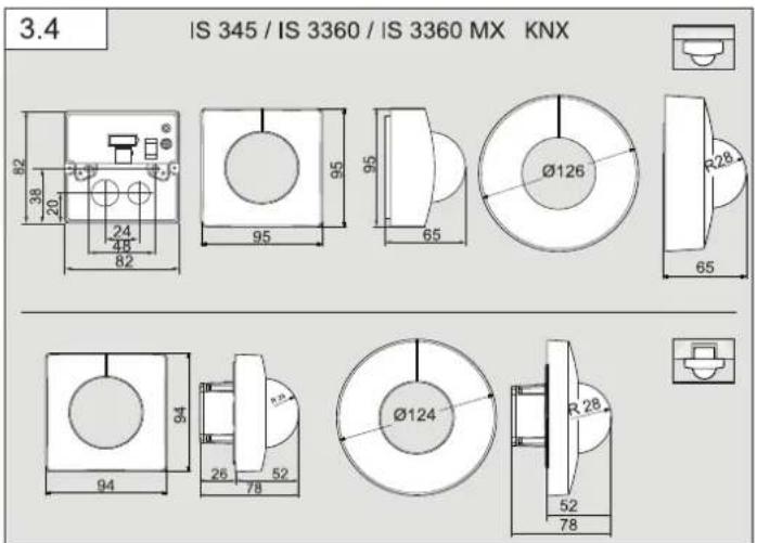
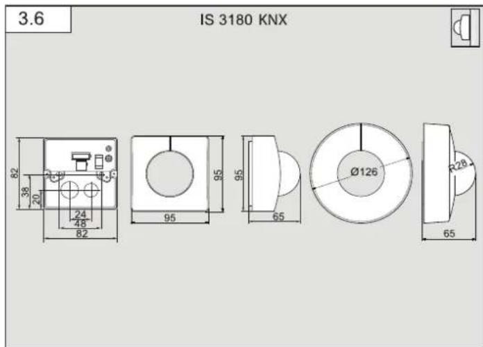
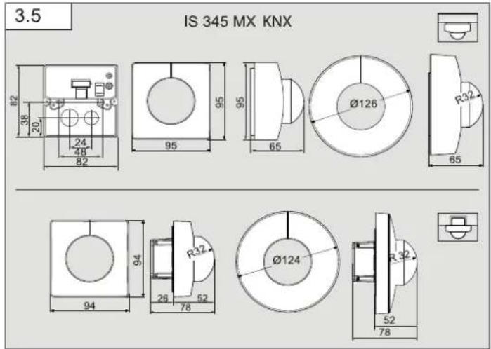
Product dimensions
Surface-mounted / concealed (Fig. 3.4)
IS 3360 KNX, IS 3360 MX KNX, IS 345 KNX
Surface-mounted / concealed (Fig. 3.5)
IS 345 MX KNX
Surface-mounted / wall-mounted (Fig. 3.6)
IS 3180 KNX
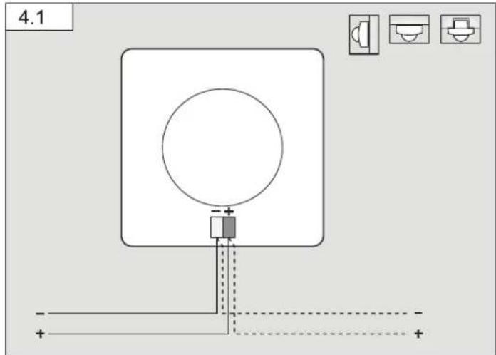
4. Installation
Wiring diagram (Fig. 4.1)
An optional corner wall mount is available for mounting the IS 3180 KNX (Prod. no. 035174 white).
– Surface-mounted installation
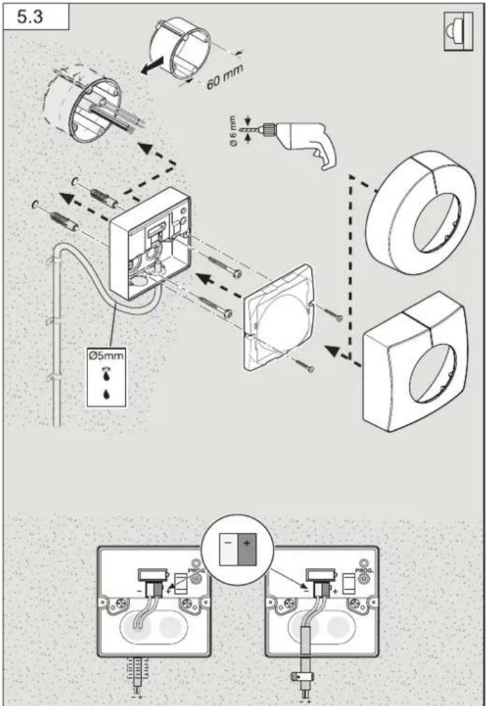
If the rubber seal is damaged, the cable entry openings must be sealed with an M16 or M20 (at least IP54) double seal cable gland.
For mounting on the wall, a condensation water drainage hole ( 5 mm drill bit) is marked next to the rubber seal. This must be opened if necessary. (Fig. 5.3)
5. Mounting
- Check all components for damage.
- Do not use the product if it is damaged.
- Select an appropriate mounting location, taking the reach and motion detection into consideration.
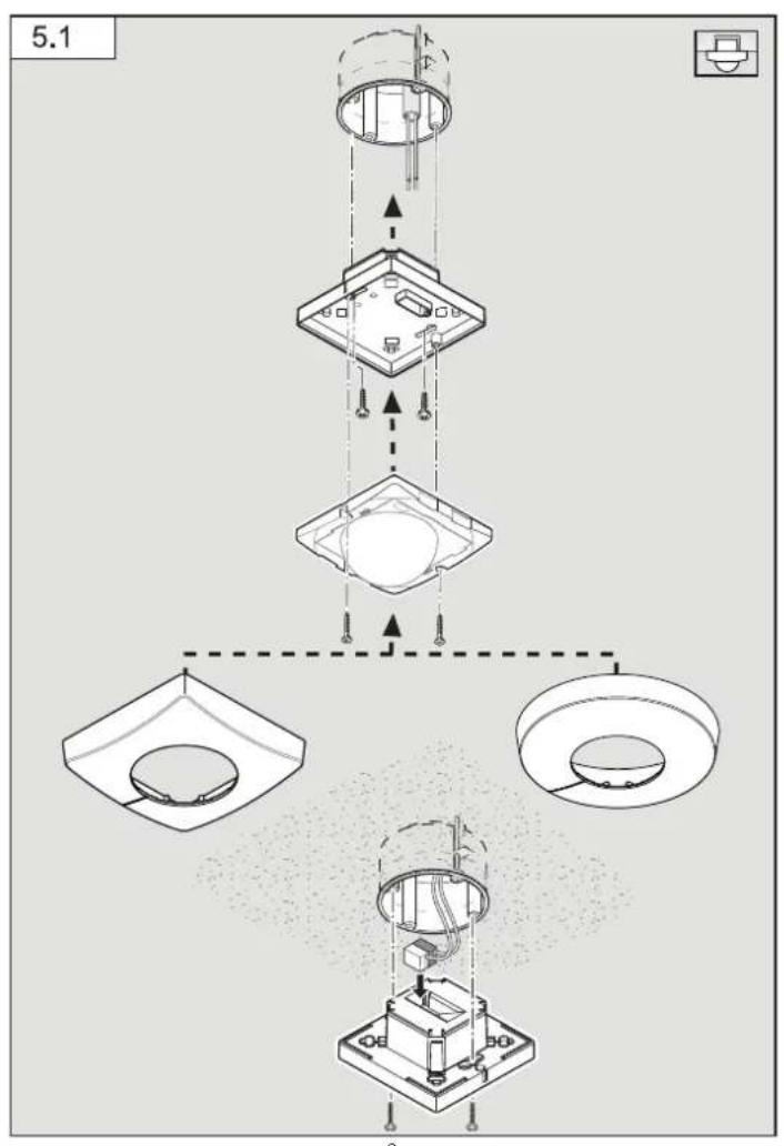
Procedure for installing concealed power supply lead (Fig. 5.1)
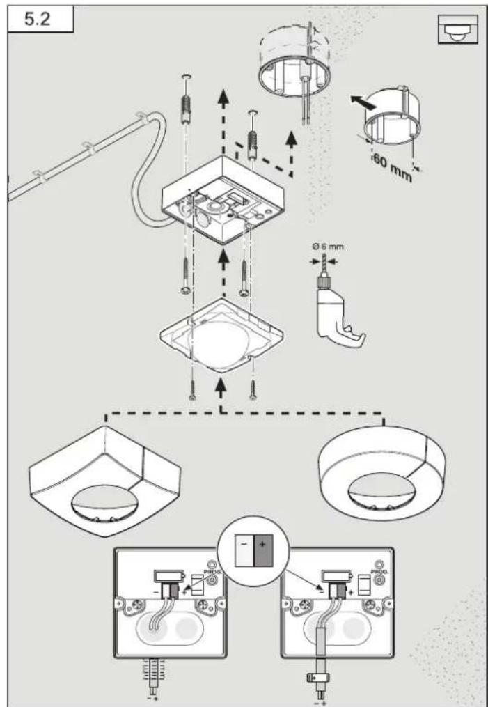
Procedure for installing surface-mounted power supply lead (Fig. 5.2)
IS 3360 KNX, IS 3360 MX Highbay KNX, IS 345 KNX, IS 345 MX Highbay KNX
Procedure for installing surface-mounted power supply lead (wall mounting) IS 3180 KNX (Fig. 5.3)
- Detach designer trim from sensor module.
- Disconnect sensor module from the load module.
Concealed mounting (Fig. 5.1)
• Make plug connection
- Press the programming button (B).
- Insert fastening screws and mount load module.
- Make settings. (→ "6. Functions and settings")
Surface mounting (Fig. 5.2 / 5.3)
- Insert fastening screws and mount load module.
- Make plug connection.
- Press the programming button (B).
- Make settings. (→6. Functions and settings")
- Fit sensor and load module together and screw into place.
- Fit designer trim.
Limiting reach
The detection zone can be optimised to suit requirements.
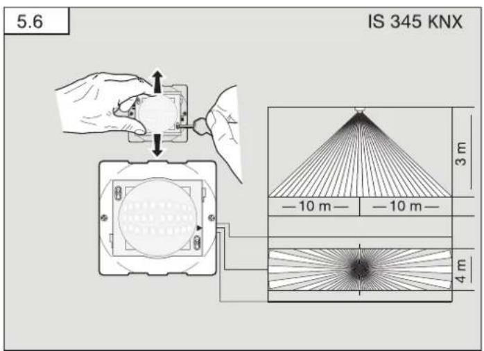
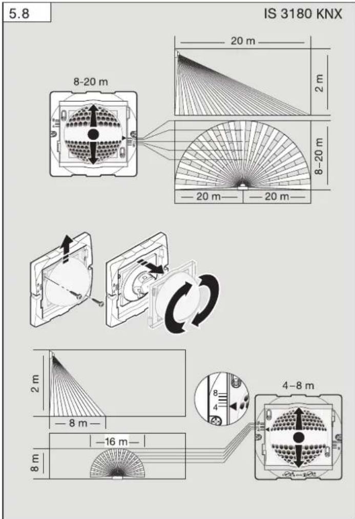
- By adjusting the lens. (Fig. 5.6 / 5.8)
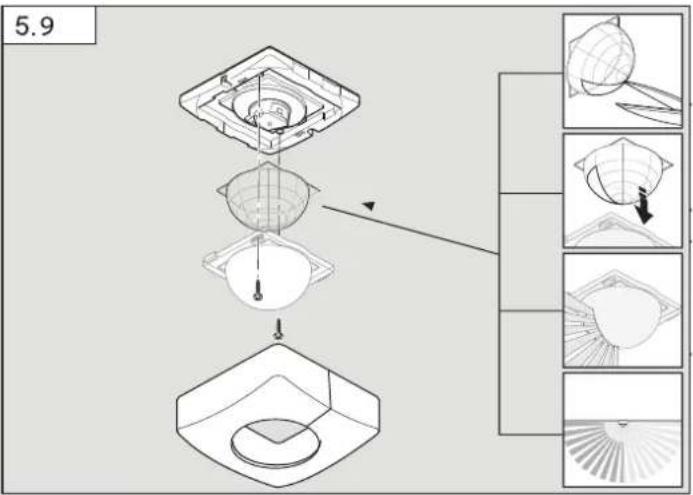
- By using the half-round clip-on shroud. (Fig. 5.9)
• To set the required reach, undo the screws or completely remove them.
- Move lens into required zone.
- The shroud provided can be used for masking out any number of lens segments to shorten reach as required.
• Afterwards, fix the lens in place with the screws.
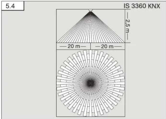
Detection zone / reach
IS 3360 KNX (Fig. 5.4)
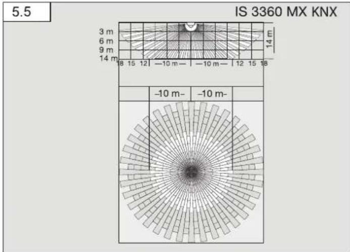
IS 3360 MX KNX (Fig. 5.5)
| Mounting height Reach | |
| 14 m 10 m | |
| 9 m 14 m | |
| 6 m 16 m | |
| 2.8 m 18 m | |
IS 3360 KNX (Fig. 5.6)
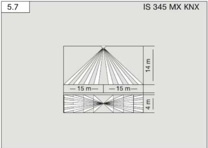
IS 345 MX KNX (Fig. 5.7)
| Mounting height Reach | |
| 14 m 30 m × 4 | |
| 10 m 25 m × 4 | |
| 8 m 20 m × 4 | |
| 6 m 15 m × 4 | |
| 4 m 10 m × 4 | |
IS 3180 KNX (Fig. 5.8)
| Mounting height | 20 m lens 8 m lens | |||||
| Setting level | tangential radial Setting level | tangential radial | ||||
| 1.5 m | 8 | 5 m | 2.5 m | 4 | 3 m | 2.0 m |
| - | 6 m | 2.5 m | - | 5 m | 2.5 m | |
| - | 7 m | 3.0 m | - | 6 m | 3.0 m | |
| - | 8 m | 3.0 m | - | 7 m | 3.0 m | |
| 20 | 12 m | 4.5 m | 8 | 9 m | 3.5 m | |
| 2.0 m | 8 | 5 m | 2.5 m | 4 | 4 m | 3.0 m |
| - | 6 m | 3.0 m | - | 5 m | 3.0 m | |
| - | 7 m | 3.5 m | - | 6 m | 3.0 m | |
| - | 10 m | 4.0 m | - | 8 m | 3.0 m | |
| 20 | max. 20 m 4.5 m 8 | 8 m | 3.5 m | |||
| 2.5 m | 8 | 6 m | 3.0 m | 4 | 5 m | 3.0 m |
| - | 8 m | 4.0 m | - | 7 m | 3.5 m | |
| - | 10 m | 5.0 m | - | 8 m | 3.5 m | |
| - | 13 m | 5.0 m | - | 9 m | 4.0 m | |
| 20 | max. 20 m 4.0 m 8 | 10 m | 3.5 m | |||
| 3.0 m | 8 | 8 m | 4.0 m | 4 | 5 m | 3.0 m |
| - | 9 m | 4.5 m | - | 6 m | 3.0 m | |
| - | 12 m | 5.0 m | - | 8 m | 4.0 m | |
| - | 17 m | 4.0 m | - | 10 m | 4.5 m | |
| 20 | max. 20 m 4.0 m 8 | 13 m | 5.5 m | |||
Note: 20 metres is preset at the factory.
- Insert fastening screws and mount load module.
- Fit sensor and load module together and screw into place.
- Set functions. (→6. Funtion")
- Fit designer trim.
6. Function
You will find an application description at knx.stinel.de
Functions to be used are selected from the "General Settings" parameter window using the Engineering Tool Software (ETS) from version ETS4.0.
-
Issue physical address and generate application program in the ETS.
-
Load the physical address and application program into the motion detector. When you are prompted, press programming button (B)
-
The red LED goes out once programming has been successfully completed.
Functions, RC6
- Servicemode
- Reach, sensor sensitivity HF
– Light level, brightness setting, teach-in - Lighting control stay-ON time
- HVAC switch-ON delay, room surveillance, HVAC stay-ON time
- Basic lighting stay-ON time, brightness setting, teach-in
- Presence- and lighting test mode
Functions, RC7
- Dimming function
- Light ON/OFF 4 h
– Saving, activating scene - Reset
Smart Remote
- Replaces remote controls RC6 and RC7
- Control via smartphone or tablet
- Load appropriate app and connect via Bluetooth
Additional functions, Smart Remote
- Programme mode
LED function
- Programming mode: LED ON
- Normal mode: LED stays OFF
- Test mode: LED lights up on detecting movement
- Remote control: LED flashes approx. 10 times per second
Detailed descriptions are provided in the operating instructions for the particular remote control.
7. Accessories
- User remote control RC6 EAN 4007841 593018
- Service remote control RC7 EAN 4007841 592912
- Smart Remote EAN 4007841 009151
8. Operation/maintenance
Weather conditions may affect the way the motion detector works. Strong gusts of wind, snow, rain or hail may cause the light to come ON when it is not wanted because the sensor is unable to distinguish between sudden changes of temperature and sources of heat. The detector lens may be cleaned with a damp cloth if it becomes dirty (do not use cleaning agents).
9. Declaration of Warranty
As purchaser, you are entitled to your statutory rights against the vendor. If these rights exist in your country, they are neither curtailed nor restricted by our Warranty Declaration. We guarantee that your STEINEL Professional sensor product will remain in perfect condition and proper working order for a period of 5 years. We guarantee that this product is free from material-, manufacturing- and design flaws. In addition, we guarantee that all electronic components and cables function in the proper manner and that all materials used and their surfaces are without defects.
Making Claims
If you wish to make a claim, please send your product complete and carriage paid with the original receipt of purchase, which must show the date of purchase and product designation, either to your retailer or contact us at STEINEL (UK) Limited, 25 Manasty Road, Axis Park, Orton Southgate, Peterborough, PE2 6UP, for a returns number. For this reason, we recommend that you keep your receipt of purchase in a safe place until the warranty period expires. STEINEL shall assume no liability for the costs or risks involved in returning a product.
For information on making claims under the terms of the warranty, please go to www.steinel-professional.de/garantie
If you have a warranty claim or would like to ask any question regarding your product, you are welcome to call us at any time on our Service Hotline 01733 366700.

- Technical specifications
| IS 3180 KNX | IS 3360 KNXIS 3360 MX KNX | IS 345 KNX IS | 345 MX KNX | |
| Dimensions(L × W × H) | Surface-mounted installation, round ∅ | 126 × 65 mm | ||
| Surface-mounted installation, square | 95 × 95 × 65 mm | |||
| Concealed installation, round ∅ | 124 × 78 mm | |||
| Concealed installation, square | 94 × 94 × 78 mm | |||
| Power supply KNX bus voltage, 21 V - 30 V —— (SELV) | ||||
| Settings via ETS software, remote control or BUS | ||||
| Sensor system Passive infrared | ||||
| Angle of coverage | 180° with 90° angle of aperture | 360° with 180° angle of aperture | 180° with 45° angle of aperture | 180° with 45° angle of aperture |
| Reaches Basic setting 1:max. 8-20 m tangential; temperature stabilisedBasic setting 2:max. 4-8 m; temperature stabilised+ precision adjustment by re-positioning the lens and using shrouds | IS 3360 KNX max. 20 m tangential; temperature-stabilisedIS 3360 MX KNX max. 18 m; temperature-stabilised+ precision adjustment using shrouds | max. 20 × 4 m (tangential), max. 12 × 4 m (radial); temperature-stabilised+ precision adjustment using shrouds | max. 30 × 4 m (radial) mounted at a height of 14 m; temperature-stabilised+ precision adjustment using shrouds | |
| Switching zones | 448 1416 | 280 120 | ||
| Twilight setting 2-1000 lux, teach | ||||
| IS 3180 KNX IS 3360 KNXIS 3360 MX KNX | IS 345 KNX IS | 345 MX KNX | ||
| Twilight setting, basic brightness | 2 - 1000 lux, teach | |||
| IP rating Surface-mounted: IP54 Concealed: IP20 | ||||
| Temperature zone | -20°C to +50°C | |||
| Light outputLight 1 – Light 2 | Switching, dimming, basic brightness | |||
| Further outputs | In-operation telegram | |||
11. Disposal
Electrical and electronic equipment, accessories and packaging must be recycled in an environmentally compatible manner.

Do not dispose of electrical and electronic equipment as domestic waste.
EU countries only:
Under the current European Directive on Waste Electrical and Electronic Equipment and its implementation in national law, electrical and electronic equipment no longer suitable for use must be collected separately and recycled in an environmentally compatible manner.
- Troubleshooting
| Malfunction Cause | Remedy | |
| No power at the sensor | ■ Break in wiring■ Fuse faulty; not switched ON; break in wiring■ Short-circuit | ■Check KNX power supply■New fuse, turn ON power switch, check wiring with voltage tester■Check connections |
| Sensor will not switch ON | ■ Twilight setting in night-time mode during daytime operation■ Lamp faulty■ Mains switch OFF■ Fuse faulty■ Detection zone not correctly adjusted | ■Reset■Replace lamp■Switch ON■Replace fuse, check connection if necessary■Readjust |
Malfunction Cause Remedy
| Sensor will not switch OFF | ■ Continued movement within the detection zone■ Light being operated is located in the detection zone and keeps switching ON as a result of temperature changes■ Light being operated is in the manual override mode (LED ON) | ■ Check zone and readjust if necessary or fit shrouds■ Adjust detection zone or fit shrouds■ Deactivate manual override |
| Sensor keeps switching ON/OFF | ■ Light being operated is located in the detection zone■ Animals moving in detection zone | ■ Adjust detection zone or fit shrouds, increase distance■ Adjust zone, or fit hrouds |
| Sensor reach change | ■ Change in ambient temperatures | ■ Use shrouds to define detection zone precisely |
| Sensor responds when it should not | ■ Wind is moving trees and bushes in the detection zone■ Cars in the street are being detected■ Sunlight is shining on the lens■ Sudden temperature changes due to weather (wind, rain, snow) or air expelled from fans, open windows■ Dazzle guard active | ■ Change detection zone■ Change detection zone■ Mount sensor in a protected place or change zone■ Adjust detection zone or install in a different place■ Operate manually at pushbutton/switch■ No movement detected within the selected stay-ON time + 60 sec. (dazzle guard)■ install at least 2 m away from the wireless communication source |
| ■ Sensor near Wi-Fi or other wireless communication sources |
CZ
| Înălțime de montaj | Treaptă de reglaj | 20 m Lentilă | Treaptă de reglaj | 8 m Lentilă | ||
| tangentțial | radial | tangentțial | radial | |||
| 1,5 m | 8 | 5 m | 2,5 m | 4 | 3 m | 2,0 m |
| -6 m | 2,5 m | -5 m | 2,5 m | |||
| -7 m | 3,0 m | -6 m | 3,0 m | |||
| -8 m | 3,0 m | -7 m | 3,0 m | |||
| 20 | 12 m | 4,5 m | 6 | 9 m | 3,5 m | |
| 2,0 m | 8 | 5 m | 2,5 m | 4 | 4 m | 3,0 m |
| -6 m | 3,0 m | -5 m | 3,0 m | |||
| -7 m | 3,5 m | -6 m | 3,0 m | |||
| -10 m | 4,0 m | -8 m | 3,0 m | |||
| 20 | 20 m | 4,5 m | 6 | 6 m | 3,5 m | |
| 2,5 m | 8 | 6 m | 3,0 m | 4 | 5 m | 3,0 m |
| -8 m | 4,0 m | -7 m | 3,5 m | |||
| -10 m | 5,0 m | -8 m | 3,5 m | |||
| -13 m | 5,0 m | -9 m | 4,0 m | |||
| 20 | 20 m | 4,0 m | 6 | 10 m | 3,5 m | |
| 3,0 m | 8 | 8 m | 4,0 m | 4 | 5 m | 3,0 m |
| -9 m | 4,5 m | -6 m | 3,0 m | |||
| -12 m | 5,0 m | -8 m | 4,0 m | |||
| -17 m | 4,0 m | -10 m | 4,5 m | |||
| 20 | 20 m | 4,0 m | 6 | 13 m | 5,5 m | |
5 ANI GARANT PRODUCATORLIT
- Date tehnice