WOOB-4004000 - Planer thicknesser MSW - Free user manual and instructions
Find the device manual for free WOOB-4004000 MSW in PDF.

User questions about WOOB-4004000 MSW
0 question about this device. Answer the ones you know or ask your own.
Ask a new question about this device
Download the instructions for your Planer thicknesser in PDF format for free! Find your manual WOOB-4004000 - MSW and take your electronic device back in hand. On this page are published all the documents necessary for the use of your device. WOOB-4004000 by MSW.
USER MANUAL WOOB-4004000 MSW
natural_image
Line drawing of a manual machine with handle and workpiece (no text or symbols)Abbildung 1
text_image
Technical diagram of a machine with labeled parts A, B, C, D and directional arrows indicating assembly or operation.Abbildung 2
text_image
Labeled diagram of a scientific instrument with components A through H, showing internal structure and directional arrows.Abbildung 3
natural_image
Close-up of a mechanical device with labeled parts A and B, showing internal components (no readable text or symbols beyond labels)Abbildung 4
text_image
A H J W G B C D E FAbbildung 7
Siehe Abbildung 7:
text_image
D E H F B A G CAbbildung 8

natural_image
Close-up of a metallic mechanical assembly with diagonal metal panels and a lever mechanism (no visible text or symbols)Abbildung 9
text_image
J H D F C B D E A GAbbildung 11

text_image
Technical diagram of a mechanical assembly with labeled components from A to P, showing internal components and assembly lines.Abbildung 13

natural_image
Diagram of a mechanical assembly with labeled component A, showing various parts arranged in a circular layout (no text or symbols beyond label)Abbildung 14
text_image
Technical diagram of a mechanical device with labeled components and an inset view of a rotary knob.Abbildung 15
Siehe Abbildung 15:
natural_image
Pure mechanical assembly diagram without any text, numbers, or symbolsAbbildung 16
Siehe Abbildung 16:
natural_image
Technical line drawing of a mechanical assembly with no visible text or symbolsAbbildung 17
natural_image
Technical line drawing of a wooden cutting tool with directional arrows indicating movement (no text or symbols)Abbildung 20
text_image
Technical diagram of a mechanical device with labeled parts A through L, showing cross-sectional and top views.text_image
Technical schematic diagram with numbered components, likely a mechanical or electrical assembly, showing various connection points and parts.text_image
Technical schematic diagram of a mechanical assembly with numbered components and labeled partstext_image
Technical schematic diagram of a mechanical assembly with numbered components and labeled partstext_image
Technical schematic diagram with numbered components and labeled parts, likely from an engineering or mechanical drawing.text_image
Technical diagram of a mechanical assembly with numbered components and labeled partstext_image
Technical diagram of a mechanical assembly with labeled parts in Chinese, showing exploded and assembled views.text_image
Technical schematic diagram with numbered components and labeled parts, likely from an engineering or mechanical drawing.This User Manual has been translated using machine translation. We have made every effort to ensure the translation is accurate, but please note that automated translations are not perfect and are not meant to replace human translators. The official version of the User Manual is in English. Any differences between the translated version and the original English are not legally binding. If you have any questions about the accuracy of the translation, please refer to the English version, which is the official reference. More language versions are available upon request via info@expondo.com.
Technical data
| Parameter description Parameter value | |
| Product name Planer & thicknesser | |
| Model | MSW-WOOB-4004000 |
| Rated voltage [V~, N] / frequency [Hz] 400, 3 / 50 | |
| Rated power [W] 4000 | |
| IP | 20 |
| Cutter block speed [/min] 5500 | |
| Knife size [mm] 410*25*3 | |
| Planer - Cutting capacity [mm] 3 | |
| Planer - Table size [mm] 1640*410 | |
| Thicknesser - Cutting capacity [mm] 4 | |
| Thicknesser - Table size [mm] 600*408 | |
| Thicknesser - Max height [mm] 225 | |
| Thicknesser - Feed speed [m/min] 7 | |
| Dimensions [width * length * height; mm] | 1650*940*965 |
| Weight [kg] | 260 |
Description
natural_image
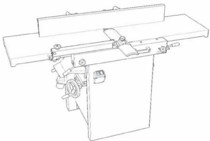
Line drawing of a manual machine with handle and workpiece (no text or symbols)Figure 1
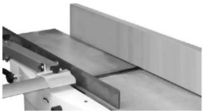
The product is a combined planer and thicknesser machine designed for use in joinery workshops. It is intended for longitudinal processing of wood and similar materials, with a maximum workpiece width of 310 mm.
The machine is designed for operations performed by one user only.
The user is liable for any damage resulting from unintended use of the device.
Specifications concerning the noise of the device
| Level of noise A in place of operation (LpAeq) | No-load | LpAeq =81.7 dB(A) |
| Load | LpAeq =89.5 dB(A) | |
| Level of acoustic power A (LWA) | No-load | L_WA = 94.5 dB(A) |
| Load | L_WA = 103 dB(A) |
Operating conditions for noise measurement comply with annex B of ISO 7960. The values given are those of emissions and do not necessarily mean any safe working values. Although there is a correlation between the value of emissions and the levels of exposure, these values cannot be used for reliable determination whether additional measures are necessary. The factors influencing actual levels of workers' exposure include the properties of the working area, other sources of noise, etc., e.g. the number of machines and the other neighboring procedures. Also, the highest permissible levels of exposure may vary in different countries. This information should help the machine user to evaluate the risk and the risk rate in a better manner.
Preparation and operating controls
Receiving
Carefully unpack the machine and any loose items from the wood crate and inspect them for damage. Any damage should be reported immediately to your distributor and shipping agent. Before proceeding further, read your manual thoroughly to familiarize yourself with proper assembly, maintenance and safety procedures.
Remove the screws that hold the machine to the shipping skid. Remove the protective coating from the table, bed rolls, feed rolls, cutterhead and loose items packed with the machine. This coating may be removed with a soft cloth moistened with kerosene. Do not use acetone, gasoline or lacquer thinner for this purpose. Do not use solvents on plastic parts.
Unpacking
-
Remove all contents from the shipping carton. Do not discard the carton or packing material until the machine is set up and running satisfactorily.
-
Inspect the contents for shipping damage. Report damage, if any, to your distributor.
-
Tools Required for Assembly:
• 1*Cross-point Screwdriver
- 1*4 mm Hex Wrench
- 1*5 mm Hex Wrench
- 1*6 mm Hex Wrench
- 1*10 mm Box Wrench
• 1*13 mm Box Wrench
Note: Use of sockets and ratchets will speed assembly time but are not required.
Work qualifications
Only an expert skilled in the field of wood-machining or a worker instructed and trained by such expert may operate the machine, regardless of the gender. While working on the machine the operator must get familiar with these instructions and comply with any safety rules, regulations and provisions in force in the respective country.
Work environment
The machine must be operated in a workshop environment, the temperature of which does not exceed +40°C and does not drop below +5°C. The relative humidity of ambient is from 30% to 95%, non-condensing. The height above the sea level is up to 1000m.
Storage and transportation temperature: -25\~+55°C
The environment classification - danger of inflammable dust fire.
Electrical connection

CAUTION! All electrical connections must be made by a qualified electrician. All adjustments or repairs must be made with the machine disconnected from the power source and unplugged. Failure to comply may result in serious injury!
This machine is not supplied with a plug. Use a plug and outlet rated at least 20amps. The circuit for the machine should also be protected by at least a 20-amp circuit breaker or fuse.
Make sure that the cutterhead moves in the correct direction. If it does not, simply reverse two of the
phase wires on the supply input.
Operating controls

CAUTION!
- Disconnect the machine from the power source before making any adjustments. Failure to comply may cause serious injury.
- Cutterhead knives are dangerously sharp. Use extreme caution when working around them. Failure to comply may cause serious injury.
Jointer to planer setup
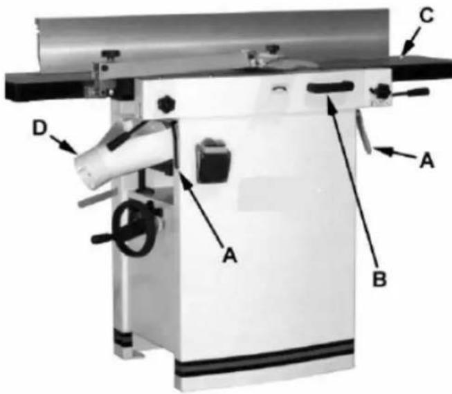
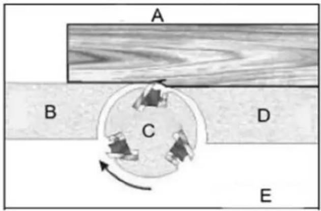
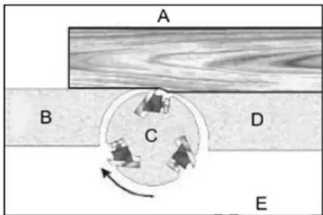
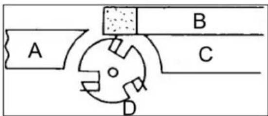
To change the machine configuration jointer to planer (refer to Figure 2):
- Release both cabinet table locks (A) by rotating the handles toward the operator, then pulling away from the machine.
- Raise the table (C) using the handle (B).
text_image
Technical diagram of a machine with labeled parts A, B, C, D and directional arrows indicating assembly or operation.Figure 2
The table is heavy. Use care when raising. Failure to comply may cause serious injury.
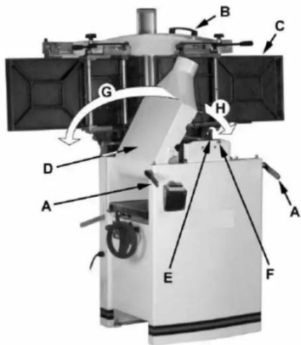
When raised, the table should be in the vertical position as shown in C, Fig. 3. The latch (E, Fig. 3) should be engaged, preventing the table from an accidental forward fall.
- Position the dust chute (D, H Fig. 3) to the right. Use extreme care to avoid contact with cutterhead knives.
Note: The planer table may need to be lowered to allow clearance needed to position the dust chute.
Planer to jointer setup
Referring to Figure 3: To change the machine configuration from planer to jointer:
- Pull the release knob (F) and reposition the dust chute (D, G) to the left. It should be positioned as shown in D, Fig. 2.
The table is heavy. Use care when lowering. Failure to comply may cause serious injury.
-
Release the latch (E) and bring the table forward using the tilt handle (B). It should be positioned as shown in C, Fig. 2.
-
Lock the table (C) by pushing the lock handles (A) in toward the machine and rotating down (away from the operator).
text_image
Labeled diagram of a satellite or spacecraft system with components A through H, showing directional arrows and structural components.Figure 3
Power
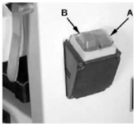
Once a properly rated plug is connected, plug the power cord into the outlet. Press the green button (A, Fig. 4) to start. Press the red off button (B, Fig. 4) to stop.
natural_image
Close-up of a mechanical component with labeled parts A and B, shown from an angle (no text or symbols beyond labels)Figure 4
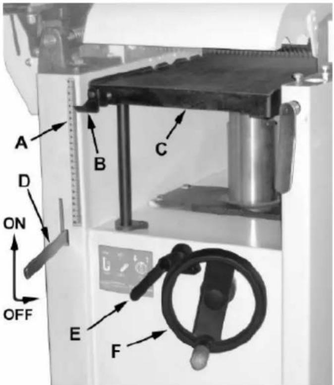
Planer controls and adjustments
text_image
A D ON OFF B C E FFigure 5
Referring to Figure 5:
Power feed
Placing the planer power feed handle (D) in the up position turns the planer power feed on (see arrow).
Placing the handle in the down position turns the power feed off.
Table lock
Turn the table lock (E) clockwise to lock the height adjustment handwheel (F) and secure the planer table (C) in its selected position. Turn the table lock (E) counterclockwise to release and permit table adjustment.
Table height adjustment
The planer table height is set as follows:
- Unlock the table lock (E).
- Rotate the height adjustment handwheel (F) clockwise to raise the planer table (C), counterclockwise to lower.
- Lock the table lock (E). Each revolution of the handwheel (F) results in a 4 mm up or down movement of the table (C). A scale on the handwheel column indicates the amount of handwheel rotation. A pointer (B) indicates the table position relative to the cutterhead on the scale (A) located on the side of the cabinet.
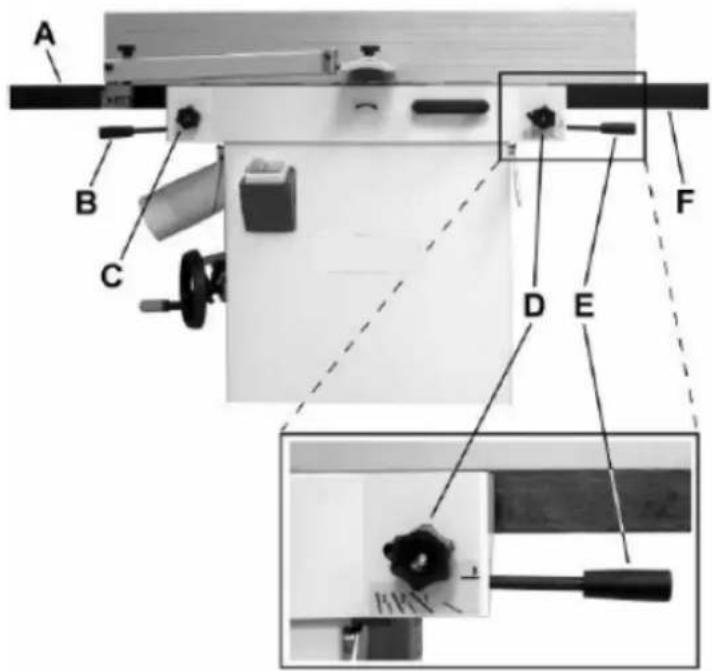
Jointer controls and adjustments
text_image
A B C D E FFigure 6
Referring to Figure 6:
Outfeed table height adjustment
Lock knob (C) and lifting handle (B) control the height adjustment of the outfeed table (A). The outfeed table is initially adjusted at the factory and should not be repositioned except during certain adjustments.
Infeed table height adjustment
Lock knob (D) and lifting handle (E) control the height adjustment of the infeed table (F). To adjust:
- Loosen lock knob (D).
- Raise the lifting handle (E) to raise the infeed table for a shallow depth of cut. Lower the handle for a deeper cut.
- Tighten the lock knob (D).
Note: A depth of cut of 1.5 mm or less is recommended.
Cutterhead guard
Properly positioned, the cutterhead guard (H) should rest against the fence (A).
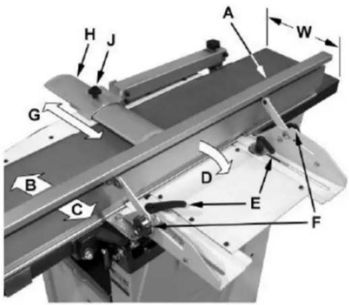
Fence movement
text_image
A H J W G B C D E FFigure 7
Referring to Figure 7:
The fence (A) can be moved forward (B) or backward (C) across the width (W) of the table. It also tilts up to 45 degrees backwards (D).
Loosen the lock knob (J), slide the guard into position, then tighten the lock knob. To slide the fence forward or backward: When edge jointing, the fence assembly should periodically be moved to different positions to distribute wear on the cutterhead knives. This is done as follows:
- If necessary, loosen the cutterhead guard (H) to permit the fence assembly to move freely without
being constrained by the guard.
- Loosen two fence assembly locking handles (E).
- Move the entire fence assembly to the desired position; then re-tighten the handles (E).
- Readjust and secure the cutterhead guard. To tilt the fence backward:
The fence (A) can be tilted backward (D) up to 45^ (that is, for a total included angle of 135^ from the table surface) as follows:
- Loosen locking handles (F).
- Tilt the fence back (A, C) to the desired angle up to 135 degrees. Or you can place your beveled reference piece on the table and against the fence, adjusting the fence until the angle of the fence matches the bevel of your gauge piece.
- Tighten the locking handles (F).
- Readjust and secure the cutterhead guard.
Adjustments
Table and knife adjustments
For accurate jointing, at least three things must be true:
- Infeed and outfeed tables must be coplanar.
- Knives or knife inserts must be set in the cutterhead so that the highest point of their arc is level with the outfeed table.
- On the standard cutterhead, knives must be parallel with the outfeed table across the entire length of the knives.
These alignments are explained below.

CAUTION! Disconnect the machine from the power source before making any adjustments.
Failure to comply may cause serious injury.
Coplanar alignment
Definition of coplanar
When the infeed table is set to the same level as the outfeed table and together both tables form a "perfect" flat surface, the tables are said to be coplanar.
For optimum performance of the jointer, the infeed and outfeed tables must be coplanar. If they are
not, the finished workpiece may have a slight taper or twist across jointed its width or length.
Determining if tables are coplanar
The tables have been set coplanar at the factory, but they should be double-checked by the operator. Also, as the machine undergoes use, the tables should be checked occasionally and adjusted if necessary.
The procedure described below uses a steel straight edge to set the tables, which should be accurate enough for most purposes.

IMPORTANT! The tables must be locked in position when performing the following test.
text_image
D H F B G A CFigure 8
natural_image
Close-up of a metallic mechanical assembly with slanted panels and metal brackets (no visible text or symbols)Figure 9
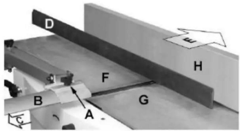
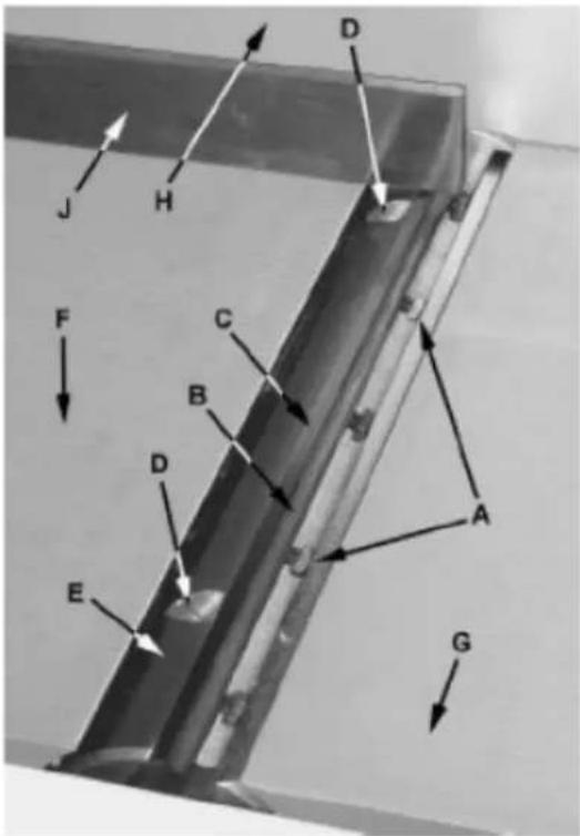
Referring to Figures 8 and 9:
- Disconnect jointer from power source.
-
Loosen the lock knob (A) and slide the cutterhead guard (B, C) to clear the table.
-
Slide the fence assembly back (H, E) as far as it will go, or remove it from the machine entirely.
- Rotate the cutterhead to avoid knife interference.
- Place a straight edge (D) across the front of the outfeed table (F) and extending over the infeed table (G). Note the position of the infeed table (G). Note the position of the straight edge in Figure 6 with respect to the fence (H).
- Raise the infeed table (G) until it contacts the straight edge (D). The straight edge should lie level across both tables. Move the straight edge to the back of the outfeed table as shown in Figure 7 and perform the same test. If the straight edge does not lie level, the front or back of one of the tables must be adjusted to make the tables coplanar.
Performing the coplanar alignment

text_image
C C1 C2 D A A1 A2 B2 B2 B B1Figure 10
If alignment is required as determined in the previous section, proceed as follows:
Disconnect the machine from the power source before making any adjustments. Failure to comply may
cause serious injury.
- Disconnect power from machine.
- Unlock both cabinet lock handles (A2).
- Raise the table (D) fully upright. Adjustment is performed by means of four setscrews (B2) that adjust the table pitch and tilt at the back (towards the fence) and two hex cap screws (A1) that adjust the table toward the front. Adjustment can consist of a front adjustment, rear adjustment or (more probable) a combination of both.
Rear adjustment
Tools required - 13 mm wrench, 4 mm hex wrench
- With a 13 mm wrench, loosen three hex cap screws (B1).
- Using a 4 mm hex wrench, make very slight adjustments of 1/8 to 1/4 turns to four setscrews (B2) as required. A clockwise turn will raise the table; a counterclockwise turn will lower the table. Adjusting the two right setscrews will have the greatest adjustment impact on the table's right side; adjusting the two left setscrews will have the greatest adjustment impact on the table's left side.
- When adjustment is complete, tighten the hex cap screws (B1)
Front adjustment
Tools required – two 13 mm wrenches
- Hold the hex cap screws (A1) in place with one wrench while using the other to loosen the locking hex nuts.
- Adjust the screws (A1) slightly from 1/8 to 1/4 turn. A counterclockwise turn will raise the table; a clockwise turn will lower the table. Adjusting the right screw will have greatest adjustment impact to the table's right side; adjusting the left screws will have greatest adjustment impact to the table's left side.
- When adjustment is complete, secure by tightening the hex nut while maintaining the position of the screw with the second wrench. It may be necessary to repeat the exercise in this section more than once to achieve co-planar alignment.
Note: If the tables do not lock properly after the adjustment, see the section "Jointer Table Lock Handle Adjustment" below.
Setng cuΣerhead knives
text_image
J H D F C B D E A GFigure 11

IMPORTANT! Before making any adjustments in this section, the infeed and outfeed tables coplanar.

CAUTION! Cutterhead knives are dangerously sharp! Use extreme caution when inspecting, ing, sharpening or replacing knives into the cutterhead. Failure to comply may cause serious injury.
- Disconnect machine from the power source.
- Remove the cutterhead guard (B, Fig. 8). Referring to Figures 11 and 12.
- Carefully number each knife blade (C) with a magic marker to differentiate each.
Note: To rotate the cutterhead the cutterhead pulley must be turned. This requires removing the panel on the back of the cabinet for access.
- Rotate the cutterhead (E) and determine the 12 o'clock position of knife number one. The 12 o'clock position is the highest point a blade will reach in the cutting arc (C, Fig. 12).
- Set a straightedge (J) on the outfeed table (F) near the fence (H). One end of the straightedge should be positioned over the cutting knife (C) near the end of the blade as shown in Fig. 9.
text_image
A B C D EFigure 12
Use care when handling the straightedge near the blades to prevent damage.
Note the position of the knife blade concerning the straight edge, then move the straightedge to the other side of the table and again note the position of the knife blade concerning the straight-edge. Blade number one must be at the same height at each end and must also be at the same height as the outfeed table (bottom of straightedge). If this is not the case, adjustment is required as follows:
- Slightly loosen five gib lock screws (A) by turning into the lock bar (B), clockwise as viewed from the infeed table (G).
- Adjust the blade height by turning the jack screws (D) upon which the blades rest. To lower the blade, turn the screw clockwise. To raise, turn the screw counter-clockwise.
- When the blade is at the proper height, alternately tighten the five gib lock screws(A).
Repeat steps 4 - 8 for blades two and three.
Replacing cutter knives

CAUTION! Disconnect machine from power source before making any adjustments. Failure to comply may cause serious injury.
- Disconnect the machine from the power source.
- Remove the cutterhead guard (B, Fig. 6).

CAUTION! Cutterhead knives are dangerously sharp. Use extreme caution when inspecting, removing, sharpening, or replacing knives into the cutterhead. Failure to comply may cause serious injury.
- Turn all five screws (A) into the lock bar (B) by turning in a clockwise direction as viewed from the infeed table (G).
- Carefully remove the cutter knife (C) and lock bar (B).
- Repeat for remaining two knives.
- Thoroughly clean all surfaces of the cutterhead, knife slots and lock bars of any dust or debris.
- Insert replacement knife (C) into the knife slot, making sure it faces the proper direction.
- Insert lock bar (B) and tighten just enough to hold in place.
- Repeat for other two blades.
Jointer table lock handle adjustment
For best performance, the jointer table lock handles (A2) should be approximately in the fully down position when in the locked position. If adjustment is required:
-
Disconnect the machine from the power source.
-
Unlock the lock handle (A2) and raise the table to the upright position.
-
Loosen the locking nut (C2) with an 18 mm wrench.
-
Adjust the table locking shaft (C1) in increments of 1/4 turns or less. Turn clockwise to tighten the lock handle performance and counterclockwise to loosen it.
-
Tighten the locking nut (C2).
-
Test the locking function and repeat if necessary.
Belt replacement
text_image
Technical diagram of a mechanical assembly with labeled components from A to P, showing internal components and assembly lines.Figure 13

CAUTION! Disconnect machine from power source before making any adjustments. Failure to
comply may cause serious injury.
Preparation
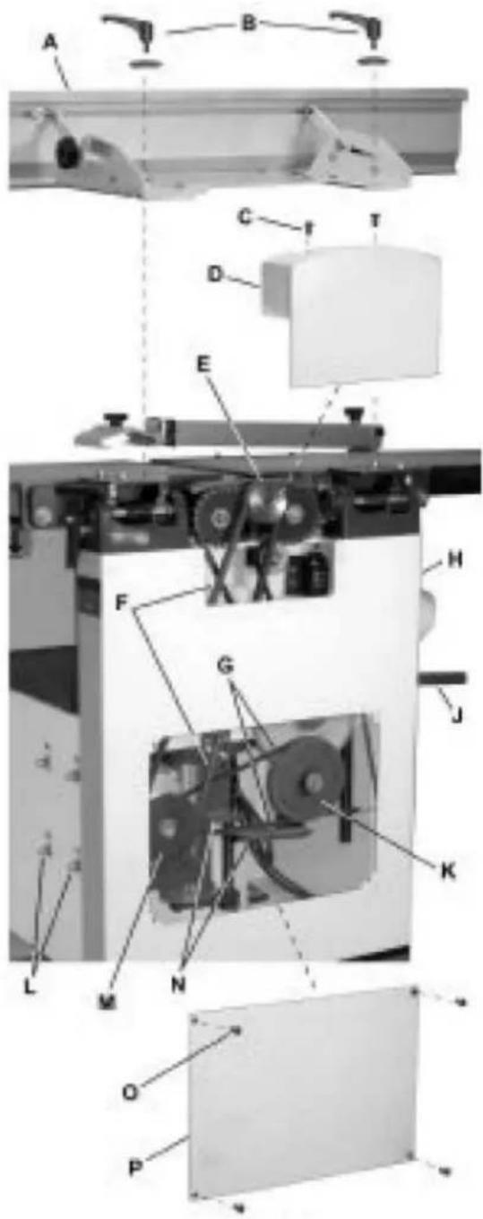
To replace the cutterhead drive belt and/or the planer feed-roller belt, the jointer fence assembly and
two back panels must first be removed as described below. A 4 mm hex wrench and two 13 mm wrenches are required.
- Remove the jointer fence assembly (A) by first loosening and removing two lock handle assemblies (B). A 4 mm hex wrench is helpful, but not necessary.
- Remove two button head socket screws (C) and upper back panel (D).
- Remove four button head socket screws (O) and lower back panel (P).
Cutterhead drive belt replacement
- Loosen four motor mount screws (L). Lift the motor and rest it on the horizontal slot side of the motor mount opening. This will create a slack in the cutterhead drive belt (F).
- Remove the cutterhead drive belt (F) from around the cutterhead pulley (E) and motor pulley (M).
- If the feed-roller belt (K) is to be replaced, continue. Otherwise proceed to step 10.
Feed-roller belt replacement
Note: If the feed-roller belt is to be replaced, steps 1–5 must be performed to remove the cutterhead drive belt before the feed-roller belt can be replaced.
- Place the power feed handle (J) in the down (off/disengaged) position, which provides belt slack for the next step.
- Remove the feed-roller belt (G) from around the feed-roller pulley (K) and motor pulley (M).
- Loop the new belt around the smaller (inner) motor pulley (M) and feed-roller pulley (K).
Note: The lower stretch of the feed-roller pulley must be positioned between the belt brake plates (N).
Concluding steps
- Replace the cutterhead drive belt (F) by looping it around the cutterhead pulley (E), then the larger (outside) motor pulley (M).
- Slide the motor so the mounting screws (L) rest back in the vertical slot openings, then tighten the mounting screws.
- Replace the lower back panel (P) and secure with four button head socket screws (O).
- Replace the upper back panel (D) and secure with two button head socket screws (C).
- Replace the jointer fence assembly (A) and secure with two lock handle assemblies (B).
Planer table adjustment

CAUTION! Disconnect machine from power source before making any adjustments. Failure to comply may cause serious injury.
Checking planer table parallel to cutterhead
The planer table is set parallel to the cutterhead at the factory and no further adjustment should be needed. If your machine is planing a taper, first check to see if the knives are properly adjusted in the cutterhead (see the section "Setting Cutterhead Knives") and make adjustments if necessary.
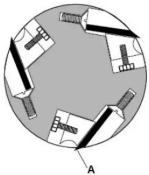
natural_image
Diagram of a circular layout with mechanical components and labeled point A (no text or symbols beyond label)Figure 14
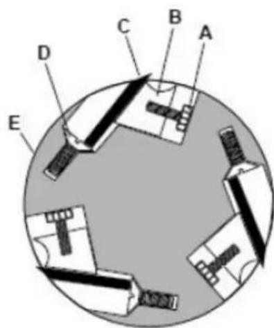
After the knives are confirmed to be properly set, check to see if the work table is set parallel to the cutterhead as follows:
- Disconnect machine from power source.
- Rotate the cutterhead such that one of the knife blades (A, Fig. 14) is at the 6 o'clock position.
text_image
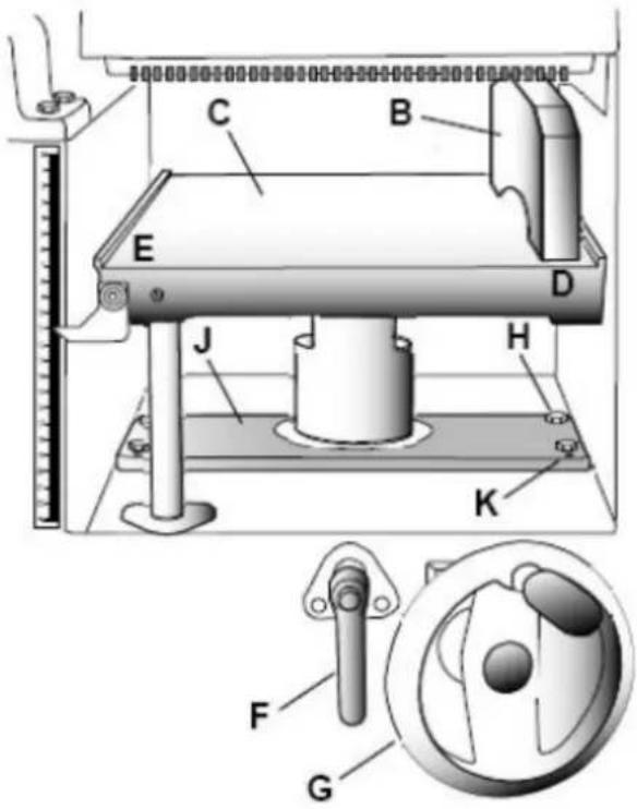
Technical diagram of a mechanical device with labeled components and a close-up inset showing a dial indicator mechanism.Figure 15
Referring to Figure 15:
- Place a gauge block (B) or another measuring device on the work table (C) at one edge (D) directly under the cutterhead.
- Unlock the table lock handle (F).
- With the handwheel (G), gently raise the table (C) until the gauge block (B) makes slight contact with the tip of the knife blade, then lock the table.
- Move the gauge block (B) to the opposite end of table (E).
If the distance from the table to tip of the knife blade is the same at both ends, the table is parallel to the cutterhead.
Adjusting worktable parallel to cutterhead
If the worktable is not parallel to the cutterhead, perform the adjustment procedure as follows:
- With a 13 mm wrench, loosen four hex cap screws (H) located at each corner of the column support (J).
- Bring the table parallel to the cutterhead by adjusting four setscrews (K) located at each corner of the column support (J) next to the hex cap screws (H).
-
Repeat steps 3 – 6, and if further adjustment is necessary, repeat steps 8, 9.
-
When the table is determined to be parallel to the cutterhead, tighten the hex cap screws (H).
Basic Operations
Dust collection
Before the initial operation, the machine must be connected to a dust collector.
Initial startup
After the assembly and adjustments are complete the planer is ready to be tested. Turn on the power supply at the main panel. Press the Start button. Keep your finger on the Stop button in case of a problem. The planer should run smoothly with little or no vibration or rubbing noises. Investigate and correct the source of any problems before further operation.
DO NOT attempt to investigate or adjust the planer while it is running.
Wait until the planer is turned off, unplugged and all working parts have come to a complete standstill.
Changing mode of operation
When changing the operating mode (planer to jointer and back) the machine must be turned off and at a complete standstill. To change the mode of operation, see sections "Jointer to Planer Setup" and "Planer to Jointer Setup".
Jointer operations
Correct operating position
The operator must be positioned offset to the infeed table.
natural_image
Pure mechanical assembly diagram without any text, numbers, or symbolsFigure 16
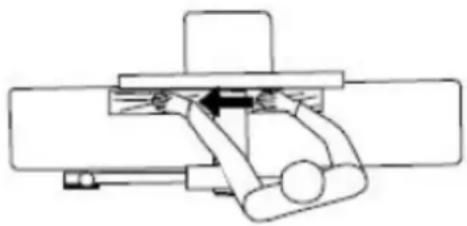
Referring to Figure 16:
At the start of the cut, the left hand holds the workpiece firmly against the infeed table and fence while the right hand pushes the workpiece in a smooth, even motion toward the cutterhead. After the cut is under way, the new surface rests firmly on the outfeed table. The left hand is transferred to the outfeed side (Figure 16) and presses down on this part of the workpiece, at the same time maintaining flat
contact with the fence. The right hand presses the workpiece forward and before the right hand reaches the cutterhead it should be moved to the work on the outfeed table.
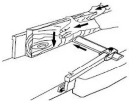
Surfacing
natural_image
Technical line drawing of a mechanical component with arrows indicating motion or force direction (no text or symbols)Figure 17
The purpose of planing on a jointer is to produce one flat surface (Figure 17). The other side can then be milled to precise, final dimensions on a thickness planer resulting in a board that is smooth and flat on both sides and each side parallel to the other.
If the wood to be jointed is cupped or bowed, place the concave side down, and take light cuts until the surface is flat.
Never surface pieces shorter than 12 inches or thinner than 3/8 inch without the use of a special work-holding fixture.
Never surface pieces thinner than 3 inches without the use of a push block.
Cuts of approximately 1/16" at a time are recommended, which provides for better control over the material being surfaced. More passes can then be made to reach the desired depth.
Direction of grain
Avoid feeding work into the jointer against the grain (Figure 18).
text_image
A B C D EFigure 18
A- Against the grain
B- Outfeed table
C- Cutterhead
D- Infeed table
E- Wrong
This may result in chipped and splintered edges. Feed with the grain to obtain a smooth surface, as shown in Figure 19.
text_image
A B C D EFigure 19
A- With the grain
B- Outfeed table
C- Cutterhead
D- Infeed table
E- Correct
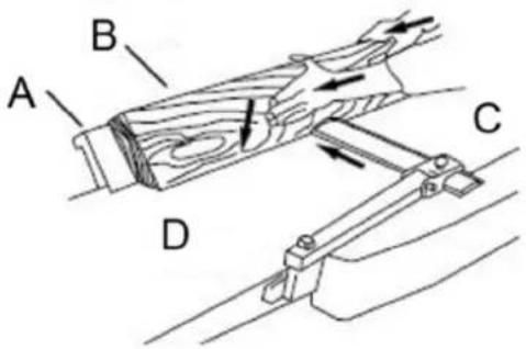
natural_image
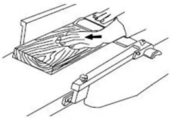
Technical line drawing of a wooden mechanical assembly with directional arrows indicating movement (no text or symbols)Figure 20
Jointing (or edging) is the process of creating a finished, flat edge surface that is suitable for joinery or finishing (Figure 20). It is also a necessary step before ripping stock to width on a table saw.
Never edge a board that is less than 3 inches wide, less than 1/4 inch thick, or 12 inches long, without using a push block.
When edging wood wider than 3 inches lap the fingers over the top of the wood, extending them back over the fence such that they will act as a stop for the hands in the event of a kickback.
Position the fence (move forward) to expose only the amount of cutterhead required.
When the workpiece is twice the length of the jointer infeed or outfeed table use an infeed or outfeed support.
To edge:
- Make sure the fence is set to 90^ . Double check it with a square.
- Inspect stock for soundness and grain direction (refer to Direction of Grain on previous page).
- If the board is bowed (curved), place the concave edge down on the infeed table.
- Set the infeed table for a cut of approximately 1.5 mm.
- Hold the stock firmly against the fence and table, feed the stock slowly and evenly over the cutterhead.
Beveling
Beveling an edge is the same operation as edge jointing, except that the fence is tilted to a specified angle.
Make certain material being beveled is over 12 inches long, more than 1/4 inch thick and 1 inch wide.
To bevel:
- Use a bevel gauge to determine the desired angle. Then set the fence to the same angle.
- Inspect stock for soundness and grain direction (refer to Direction of Grain on previous page).
- Set the infeed table for a cut of approximately 1.5 mm.
- If the board is bowed (curved), place the concave edge down on the infeed table.
- Feed the stock through the cutterhead, making sure the face of the stock is completely flat against the fence and the edge is making solid contact on the infeed and outfeed tables (Figure 21).
For wood wider than 3 inches – hold with fingers close together near the top of the stock, lapping over the board and extending over the fence. For wood less than 3 inches wide – use beveled push blocks and apply pressure toward the fence. Keep fingers near top of push block. Several passes may be required to achieve the full bevel will probably take several passes.
text_image
A B C DFigure 21
A- Fence
B- Stock
C- Infeed table
D- Outfeed table
Planer Operations
Depth of cut
Thickness planing refers to the sizing of lumber to a desired thickness while creating a level surface parallel to the opposite side of the board. Board thickness that the planer will produce is indicated by the scale and the depth of-cut gauge. Preset the planer to the desired thickness of the finished workpiece using the gauge. The depth-of-cut is adjusted by raising or lowering the planer table (C, Fig. 5) using the handwheel (F, Fig. 5).
The quality of thickness planning depends on the operator's judgment about the depth of cut.
The depth of cut depends on the width, hardness, dampness, grain direction and grain structure of the wood.
The maximum thickness of wood that can be removed in one pass is 1/8" for planning operations on workpieces up to 5-1/2" wide.
The workpiece must be positioned away from the center tab on the roller case to cut 1/8".
The maximum thickness of wood that can be removed in one pass is 1/16" for planning operations on workpieces from 5-1/2" up to 12" wide.
For optimum planning performance, the depth of cut should be less than 1/16".
The board should be planed with shallow cuts until the work has a level side. Once a level surface has been created, flip the lumber and create parallel sides.
Plane alternate sides until the desired thickness is obtained. When half of the total cut has been taken from each side, the board will have a uniform, moisture content and additional drying will not cause it to warp.
The depth of cut should be shallower when the workpiece is wider.
When planning hardwood, take light cuts or plane the wood in thin widths. Make a test cut with a test piece and verify the thickness produced.
Check the accuracy of the test cut before working on the finished product.
Precautions
A thickness planer is a precision woodworking machine and should be used on quality lumber only.
Do not plane dirty boards; dirt and small stones are abrasive and will wear out the blade.
Remove nails and staples. Use the planer to cut wood only.
Avoid knots. Heavily cross-grained wood makes knots hard. Knots can come lose and jam the blade. Any article that encounters planer blades may be forcibly ejected from the planer creating a risk of injury.
Preparing the work
A thickness planer works best when the lumber has at least one flat surface. Use a jointer to create a flat surface.
Twisted or severely warped boards can jam the planer. Rip the lumber in half to reduce the magnitude of the warp.
The work should be fed into the planer in the same direction as the grain of the wood. Sometimes the wood will change directions in the middle of the board. In such cases, if possible, cut the board in the middle so the grain direction is correct.
Do not plane a board that is less than 6" long. It is recommended that when planning short boards you
butt them end to end to avoid kickback and reduce snipe.
Feeding the work
The planer is supplied with planer blades mounted in the cutterhead and infeed and outfeed rollers adjusted to the correct height. The planer feed is automatic; it will vary slightly depending on the type of wood.
Preparation:
Feed rate refers to the rate at which the lumber travels through the planer. The operator is responsible for aligning the work so it will feed properly.
Raise or lower the roller case to get the depth of cut desired.
The surface that the planer produces will be smoother if a shallower depth of cut is used.
Stand on the side that the handle is attached.
Boards longer than 24" should have additional support from free standing material stands.
Planing:
- Position the workpiece with the face to be planed on top.
- Turn the planer on.
- Turn the power feed on.
- Rest the board end on the infeed roller plate and direct the board into the planer.
- Slide the workpiece into the infeed side of the planer until the infeed roller begins to advance the workpiece.
- Let go of the workpiece and allow the automatic feed to advance the workpiece.
- Do not push or pull on the workpiece. Move to the rear and receive the planed lumber by grasping it in the same manner that it was fed.
To avoid the risk of injury due to kickbacks, do not stand directly in line with the front or rear of the planer.
-
Do not grasp any portion of the board that has not gone past the outfeed roller.
-
Repeat this operation on all of the boards that need to be the same thickness.
Avoiding snipe
Snipe refers to a depression at either end of the board caused by an uneven force on the cutterhead when the work is entering or leaving the planer.
Snipe will occur when the boards are not supported properly or when only one feed roller is in contact with the work at the beginning or end of the cut.
Precautions for avoiding snipe:
Push the board up while feeding the work until the outfeed roller starts advancing it.
Move to the rear and receive the planed board by pushing it up when the infeed roller looses contact with the board.
When planning more than one board of the same thickness, butt the boards together to avoid snipe.
Make shallow cuts. Snipe is more apparent when deeper cuts are taken.
Feed the work in the direction of the grain. Work fed against the grain will have chipped, splintered edges.
Maintenance
Blade care

CAUTION! Blades are extremely sharp! Use caution when cleaning or changing. Failure to
comply may cause serious injury!
The condition of the blades will affect the precision of the cut. Observe the quality of the cut that the planer produces to check the condition of the blades.
Dull blades will tear, rather than cut the wood fibers and produce a fuzzy appearance.
Raised grain will occur when dull blades pound on wood that has varying density. A raised edge will also be produced where the blades have been nicked. When gum and pitch collect on the blades, carefully remove with a strong solvent. Failure to remove gum and pitch build up may result in excessive friction, blade wear and overheating. When blades become dull, touch up blades. See the section “Sharpening the Knives”.
Sharpening the knives

CAUTION! Blades are extremely sharp! Use caution when handling. Failure to comply may
cause serious injury!
text_image
A B C DFigure 22
A- Outfeed table
B- Oilstone partly covered with paper
C- Infeed table
D- Cutter
- Disconnect the machine from the power source.
- Remove the blade guard and belt cover.
- To protect the infeed table from scratches, partially cover the sharpening stone with paper (Figure 22).
- Lay the stone on the infeed table.
- Lower the infeed table and turn the cutterhead by turning the cutterhead pulley. The infeed table height is set properly when the stone's surface is flush with the knife bevel.
- Keep the cutterhead from rotating by grasping the cutterhead pulley while sliding the stone back and forth across the table.
- Take the same amount of passes for all three blades.
When the blades have been sharpened and still are not cutting efficiently, trying to touch up the blades further will only cause the formation of a second beveled edge. When this starts to happen, it is time to replace blades with another set. It is recommended to keep a second set of blades on hand so that they may be installed while the first set is being professionally sharpened.
Lubrication
Use a good grade of light grease on the steel adjusting screws located in the raising and lowering mechanisms of the worktables.
The cutterhead ball bearings are lifetime lubricated and need no further care.
Transportation and storage
- While transporting or handling the machine, be most careful and let this activity be done by qualified personnel especially trained for this kind of activity.
- While the machine is being loaded or unloaded, make sure that no person or subject gets pressed by the machine.
- Do not enter the area under the machine lifted by a crane or a high-lift trolley.
- During transporting or storing the machine, means must be taken to protect the machine against excessive vibrations and humidity.
• It should be stored in a shelter at temperatures ranging from -25^ to 55^ . - As standard, the machine is wrapped up in a plastic tray and is transported this way. Upon request, the machine may also be packed in a robust wooden box.
Disposing of used devices
Do not dispose of this device in municipal waste systems. Hand it over to an electric and electrical device recycling and collection point. Check the symbol on the product, instruction manual, and packaging. The plastics used to construct the device can be recycled following their markings. By choosing to recycle you are making a significant contribution to the protection of our environment.
Contact local authorities for information on your local recycling facility.
Troubleshooting
Performance troubleshooting – jointer
| Problem | Possible | cause |
| The finished stock is concave on the back end | The knife is higher than the outfeed table | Align cutterhead knives with the outfeed table. See the section “Setting Cutterhead Knives” |
| Finished stock is concave on the front end | The outfeed table is higher than a knife | Align cutterhead knives with the outfeed table, See the section “Setting Cutterhead Knives” |
| Chip cut | Cutting against the grain | Cut with the grain whenever possible |
| Dull knives Sharpen or replace knives | ||
| Feeding workpiece too fast Use a slower rate of feed | ||
| Cutting too deeply Make shallower cuts | ||
| Knots. imperfections in wood | Inspect wood closely for imperfections: use different stock if necessary | |
| Fuzzy grain | Wood has a high moisture content | Allow the wood to dry or use different stock |
| Dull knives Sharpen or replace knives/inserts | ||
| Cutterhead slows while operating | Feeding workpiece too quickly. Or applying too much pressure to the workpiece | Feed more slowly. or apply less pressure to the workpiece |
| “Chatter” marks on the workpiece | Knives incorrectly set | Set knives properly as described in the section “Setting Cutterhead Knives”. Check that knife slots are clean and free of dust or debris |
| Feeding workpiece too fast | Feed the workpiece slowly and consistently | |
| Uneven knife marks on the workpiece | Knives are nicked, or out of alignment | Align knives per the section “Setting Cutterhead Knives”. Replace nicked knives. |
Performance troubleshooting – planer
| Problem | Possible | cause |
| SnipeNote: Snipe can be minimized but not eliminated | Table rollers are not set properly. | Adjust rollers to the proper height. |
| Inadequate support of longboards. | Support longboards with extension rollers. | |
| Uneven feed roller pressure front to back. | Adjust feed roller tension. | |
| Dull knives. | Sharpen knives. | |
| The lumber is not butted properly. | Butt end to end each piece of stock as they pass through. | |
| Fuzzy Grain | Planing wood with high moisture content. | Remove high moisture content from wood by drying. |
| Dull knives. | Sharpen or replace. | |
| Torn Grain | Too heavy a cut. | Adjust the proper depth of cut. |
| Knives cutting against the grain. | Cut along the grain. | |
| Dull knives. | Sharpen knives. | |
| Rough/Raised Grain | Dull knives. | Sharpen knives. |
| Too heavy a cut. | Adjust proper depth. | |
| Moisture content is too high. | Remove high moisture content from wood by drying. | |
| Rounded, glossy surface | Dull knives. | Sharpen or replace knives. |
| The feed speed is too slow. | Increase speed. | |
| Cutting depth too shallow. | Increase depth. |
Solution
| Poor feeding of lumber | Inadequate feed roller pressure. | Adjust feed roller tension. If proper tension cannot be achieved, replace feed rollers. |
| Planer bed rough or dirty. | Clean pitch and residue, and wax planer table. | |
| Transmission v-belt slipping. | Tighten transmission v-belt. | |
| The surface of the feed rollers is clogged. | Clean pitch and residue out of teeth. | |
| Uneven depth of cut side-to-side | Knife projection. | Adjust knife projection. |
| The cutterhead is not level with the bed. | Level bed. | |
| The board thickness does not match the depth of the cut scale | The depth of the cut scale is incorrect. | Adjust the depth of the cut scale. |
Mechanical troubleshooting – planer/jointer
| Problem | Possible | cause |
| Chain jumping | Inadequate tension. | Adjust chain tension. |
| Sprockets misaligned. | Align sprockets. | |
| Sprockets worn. | Replace sprockets. | |
| The machine will not start/restart or repeatedly trip the circuit breaker or blow fuses. | No incoming power. | Verify unit is connected to power, the on-button is pushed in completely, and the stop-button is disengaged. |
| Overload automatic reset has not reset. | When the planer overloads on the circuit breaker built into the motor starter, it takes time for the machine to cool down before restarting. Allow the unit to adequately cool before attempting to restart. If the problem persists, check the amp setting on the motor starter inside the electrical box. | |
| Planer frequently trips. | One cause of overloading trips, which are not electrical in nature, is too heavy a cut. The solution is to take a lighter cut. If too deep a cut is not the problem, then check the amp setting on the overload relay. Match the full load amps on the motor as noted on the motor plate. If the amp setting is correct |
Solution
| then there is probably a loose electrical lead. Check the amp setting on the motor starter. | ||
| Building circuit breaker trips or fuse blows. | Verify that the planer is on a circuit of the correct size. If the circuit size is correct, there is probably a loose electrical lead. Check the amp setting on the motor starter. | |
| Loose electrical connections. | Go through all the electrical on the planer including motor connections, verifying the tightness of each. Look for any signs of electrical arcing which is a sure indicator of loose connections or circuit overload. | |
| Motor starter failure. | Examine motor starter for burned or failed components. If damage is found, replace the motor starter. If the motor starter looks okay but is still suspect, you have two options: have a qualified electrician test the motor starter for function, or purchase a new starter and establish if that was the problem on changeout. | |
| Switch or Motor failure – how to distinguish | If you have access to a voltmeter, you can separate a starter failure from a motor failure by first verifying incoming voltage at 220+/-20 and second, checking the voltage between the starter and motor at 220+/-20. If the incoming voltage is incorrect, you have a power supply problem. If the voltage between the starter and motor is incorrect, you have a starter problem. If the voltage between the starter and motor is correct, you have a motor problem. | |
| Motor failure. | If an electric motor is suspect, you have two options: Have a qualified electrician test the motor forfunction or remove the motor and take it to a quality electric motor repair shop and have it tested. | |
| Miswiring of the unit. | Double-check to confirm all electrical connections are correct and properly tight. The electrical connections other than the motor are pre-assembled and tested at the factory. Therefore, the motor connections should be double-checked as the highest probability of error. If problems persist, double-check the factory wiring. |
Parts diagram
Features
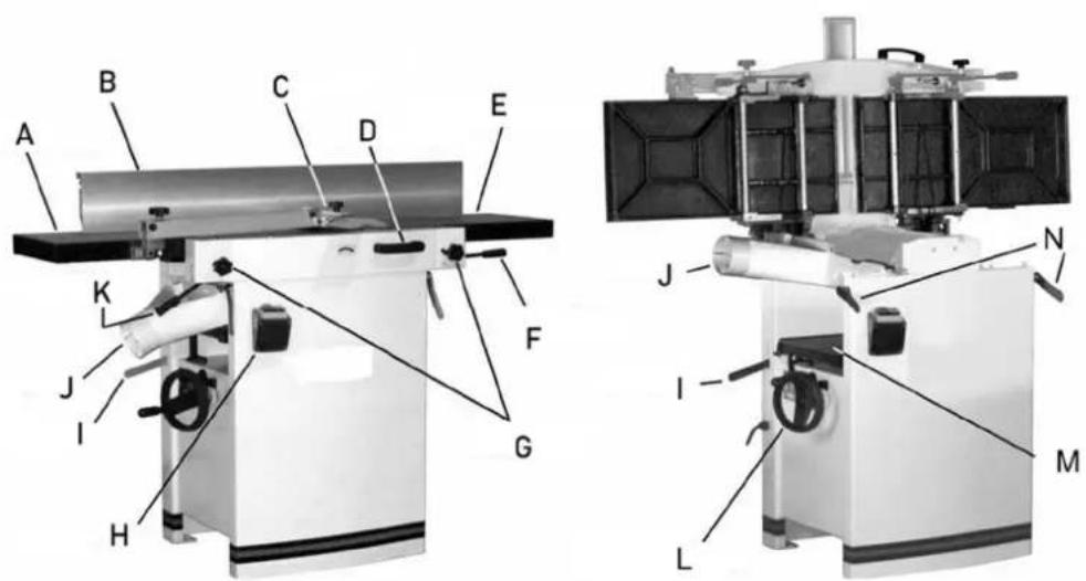
text_image
Technical diagram of a mechanical device with labeled parts A through L, showing cross-sectional and top views.| Part number Description | |
| A Jointer outfeed table | |
| B | Jointer |
| C | Cutterblock |
| D Table tilt handle | |
| E | Jointer |
| F Infeed table lifting handle | |
| G Jointer table lock knob | |
| H | On/off |
| I Power feed on/off handle | |
| J | Dust |
fence
guard
infeed
switch
hood
| K Outfeed table lifting handle | |
| L Planer table height adjustment | |
| M | Planer |
| N | Table |
table
lock
Cutter block guard and outfeed assembly
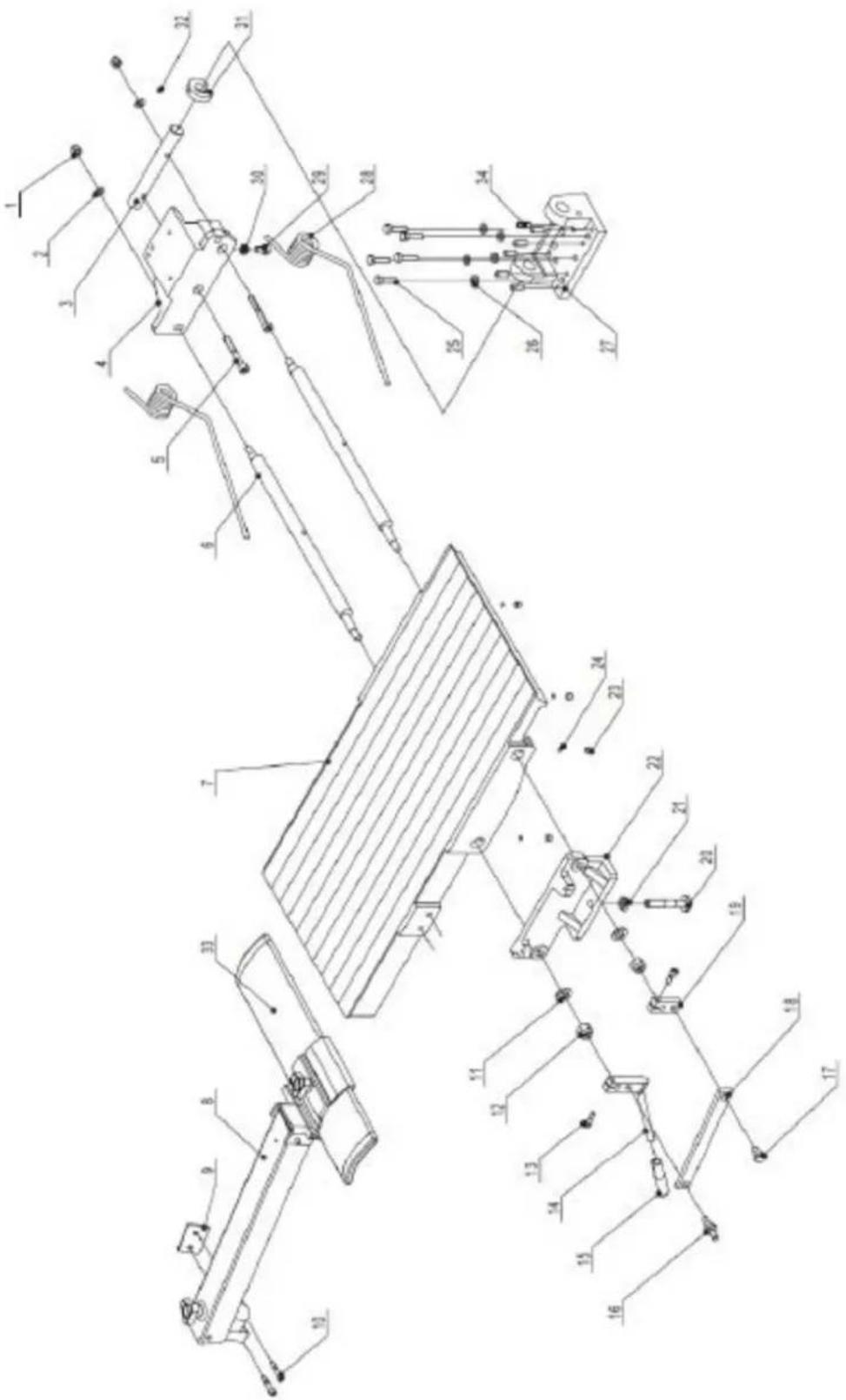
text_image
Technical schematic diagram with numbered components, likely a mechanical or electrical assembly, showing various connection points and parts.| Part number | Description Size Quantity | ||
| 1 | Lock | nut. | M8 |
| 2 | Washer. | ||
| 3 Outfeed | table bracket shaft. 1 | ||
| 4 Outfeed | table bracket right. 1 | ||
| 5 Hex. Socket cap screw M8X60 4 | |||
| 6 | Eccentric shaft. | 4 | |
| 7 | Outfeed Table. | 1 | |
| 8 | Cutterblock guard assembly. | 1 | |
| 9 | Cutterblock guard bracket. | 1 | |
| 10 Hex. Socket cap screw M6X30 2 | |||
| 11 | Washer. | H12 | 4 |
| 12 | Lock nut. | M12 | 4 |
| 13 Hex. Socket cap screw M8X20 4 | |||
| 14 | Adjusting handle. | 2 | |
| 15 | Knob. | 2 | |
| 16 | Special screw. | 2 | |
| 17 | Special screw. | 2 | |
| 18 | Eccentric shaft bracket. | 2 | |
| 19 | Eccentric shaft clamp. | 2 | |
| 20 | Table locking shaft. | 2 | |
| 21 | Hex. Nut. | M12 | 2 |
| 22 Outfeed | table bracket left. 1 | ||
| 23 | Hex. Socket set screw | M8X10 8 | |
| 24 | Plastic disc. | D6 | 8 |
| 25 | Hex. Bolt. | M8X30 | 10 |
| 26 | Washer. | H8 | 10 |
| 27 | Outfeed table support. | 2 | |
| 28 | Spring (dia 6.5 mm). | 4 | |
| 29 | Hex. bolt. | M8X16 | 2 |
| 30 | Hex. nut. | M8 | 3 |
| 31 | Big cam wheel for safety switch. | 1 | |
| 32 | Hex. Socket set | M5X10 1 | |
| 33 | Cutterblock guard profile w/cap 1 | ||
| 34 | Grub screw | M8 | 12 |
Cutter block assembly
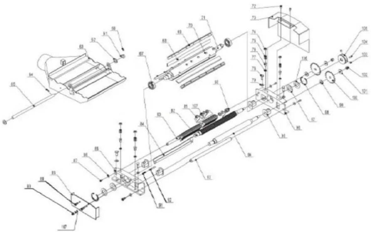
text_image
Technical schematic diagram of a mechanical assembly with numbered components and labeled parts| Part number | Description Size Quantity | ||
| 60 | Hex. Socket set screw M5X10 1 | ||
| 61 | Small cam wheel for safety switch 1 | ||
| 62 | Washer | H16 | |
| 63 | Dust collector assembly 1 | ||
| 64 | Pin | roll | N5X18 |
| 65 | Shaft | 1 | |
| 66 | Washer | H16 | |
| 67 | Bearing BRG6205-ZZCM | 2 | |
| 68 | Knife | 3 | |
| 69 | Knife locking bar 3 | ||
| 70 | Special screw for locking bar | 18 | |
| 71 | Cutter block | 1 | |
| 72 | Pan head screw | M6X12 4 | |
| 73 | Belt cover | 1 | |
| 74 | Screw | 4 | |
| 75 | Spring | 4 | |
| 76 | Hex. bolt | M8X16 | 4 |
| 77 | Hex. nut | M8 | 4 |
| 78 | Hex. bolt | M10X25 | 4 |
| 79 | Washer | H10 | |
| 80 | Adjusting | washer | |
| 81 | Anti-kickback | finger | |
| 82 | Infeed | roller | |
| 83 | Anti-kickback | shaft | |
| 84 | Cutterblock | cover | |
| 85 | Cutterblock | bracket-right | |
| 86 | Washer | M6 | |
| 87 | Hex. Socket cap screw | M6X12 | 4 |
| 88 | Cutterblock bracket cover | ||
| 89 | Pan head screw | M6X12 | 2 |
| 90 | Cap nut | M6 | |
| 91 | Spring | ||
| 92 | Pin stop for Dust collector | 1 | |
| 93 | Support rod | ||
| 94 | Outfeed roller | ||
| 95 | Tube (Powder Metal Bushing) | 4 | |
| 96 | Cutterblock bracket-left | ||
| 97 | Wave washer | D52 | |
| 98 | Retaining ring | CLP52 | 2 |
| 99 | Washer | ||
| 100 | Drive chain sprocket | 2 | |
| 101 | Washer | WSH10 | 2 |
| 102 | Lock nut | M10 | |
| 103 | Hex. Socket set screw | M8X6 | 2 |
| 104 | Key | PLN6X16 | 1 |
| 105 | Spindle pulley | 1 | |
| 106 | Washer | D52 | 2 |
| 107 | Spacer | 1 |
Base assembly
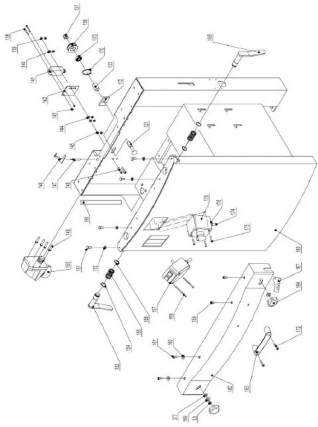
text_image
Technical schematic diagram of a mechanical assembly with numbered components and labeled parts| Part number | Description Size Quantity | ||
| 131 | Carriage | bolt | |
| 132 | Square | washer | |
| 133 | Tube | ||
| 135 | Bearing | BRG80101 | |
| 136 | Chain | wheel | |
| 136A | Chain tension wheel assembly (131-137, 170, 171) | 1 | |
| 137 | Lock | nut | |
| 138 Pan head screw M4X35 2 | |||
| 139 | Lock | nut | |
| 140 | Washer | H6 | |
| 141 | Safety | switch | |
| 142 | Safety switch bracket | 1 | |
| 143 | Lock | nut | |
| 144 | Washer | H6 | 4 |
| 145 | Hex. Nut | M6 | 2 |
| 146 | Safety switch rocker | 1 | |
| 147 | Safety switch rocker shaft | 1 | |
| 148 | Hex. Socket cap screw | M6X25 2 | |
| 149 Pan head screw M4X16 4 | |||
| 150 | Plug 230/50/1 | 1 | |
| 150A | Plug 400/50/1 | 1 | |
| 151 | Special bolt | 4 | |
| 152 | Hex. Nut | M8 | 4 |
| 153 | Lock handle for outfeed table | 1 | |
| 154 | Retaining ring | CLP20 | 4 |
| 155 | Spring | 2 | |
| 156 | Direction label | 1 | |
| 157 | Switch 230/50/60/1 | 1 | |
| 157A | Switch 400/50/1 | 1 | |
| 158 Pan head screw N4X60 | 2 | ||
| 159 Pan head screw M6X16 2 | |||
| 160 Pan head screw M6X12 2 | |||
| 161 | Washer | H6 | 7 |
| 162 | Front cover | 1 | |
| 163 | Handle | 1 | |
| 164 | Lock knob | 4 | |
| 165 | Cabinet | 1 | |
| 165A | Cabinet Cover (rear cabinet cover, not shown) | 1 | |
| 166 | Lock handle for infeed table | 1 | |
| 167 | Infeed scale | 1 | |
| 168 | Thickness scale | 1 | |
| 169 | Washer | H8 | 2 |
| 170 | Retaining ring | 1 | |
| 171 | Washer | H12 | |
| 172 | Hex socket head screw | M8X20 2 | |
| 173 | Screw | M4X10 | |
| 174 Cable for safety switch 1 | |||
| 175 | Strain | relief | |
| 176 | E-stop | button | |
Infeed table assembly
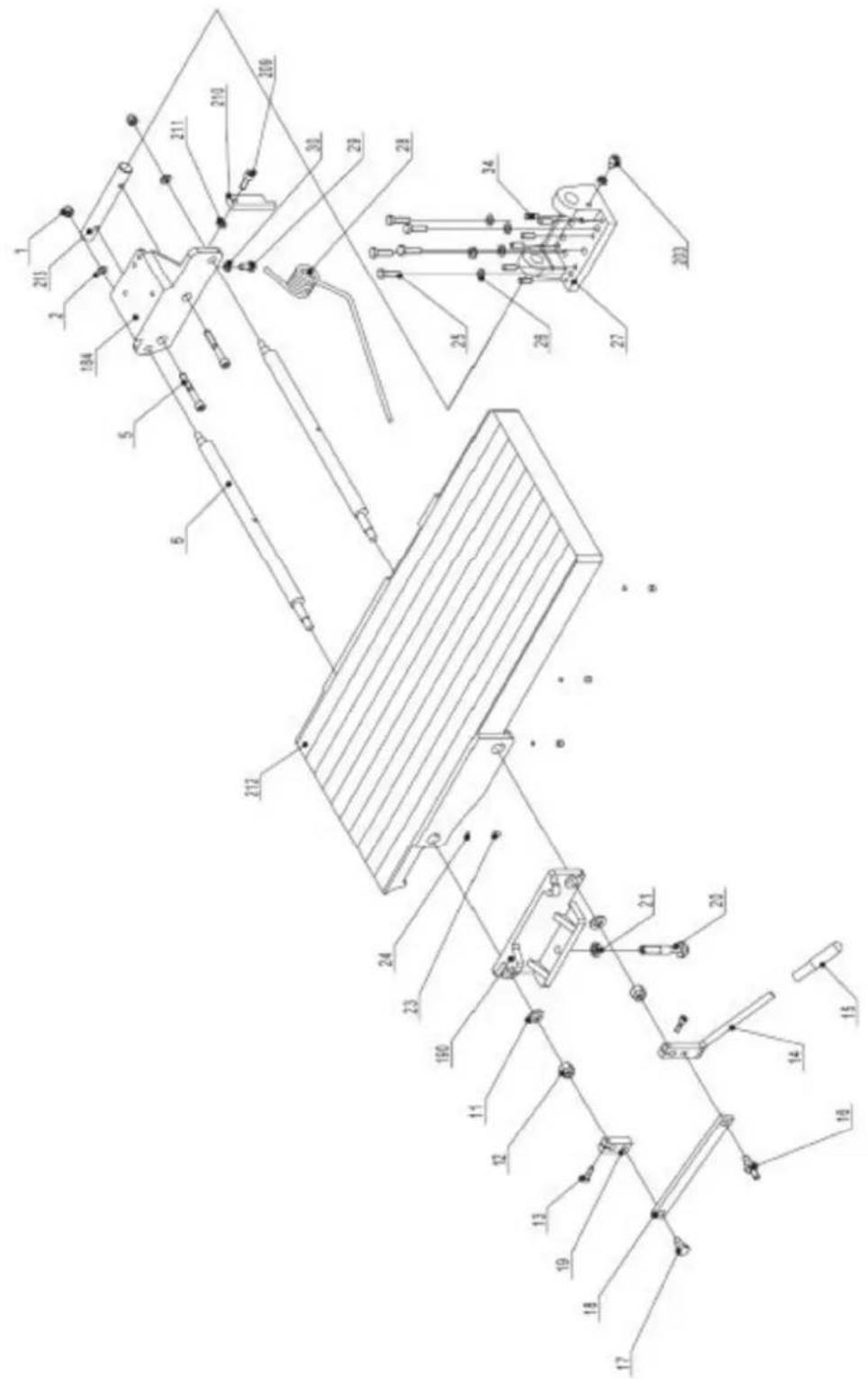
text_image
Technical schematic diagram with numbered components and labeled parts, likely from an engineering or mechanical drawing.| Part number | Description Size Quantity | ||
| 184 Infeed | table bracket right M8X60 2 | ||
| 190 Infeed | table bracket left 1 |
| 203 Hex. Socket cap screw M8X16 1 | ||
| 209 Hex. Socket cap screw M8X40 1 | ||
| 210 Table stopper | ||
| 211 Hex. | Nut | |
| 212 Infeed | table | |
| 213 Infeed table bracket shaft 1 |
Drive and motor assembly
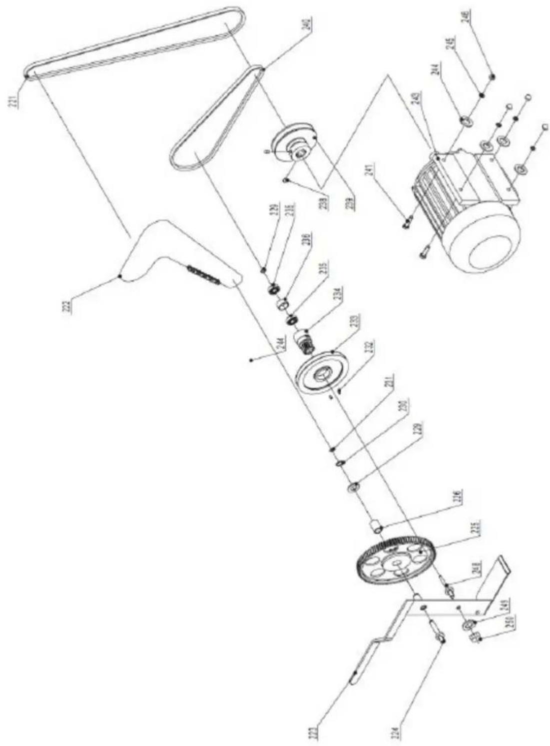
text_image
Technical diagram of a mechanical assembly with numbered components and labeled parts| Part number | Description Size Quantity | ||
| 221 | V-belt for outblock 50Hz XPA1250 1 | ||
| 222 | Drive | chain | |
| 223 | Cam wheel bracket 1 |
| 224 Cam wheel shaft 1 | ||
| 225 | Plastic Gear wheel assembly | |
| 226 | Tube (Bushing) | |
| 229 | Washer | |
| 230 | Retaining | ring |
| 231 | Retaining | ring |
| 232 Hex. Socket set screw M5x10 2 | ||
| 233 | V-belt pulley for feed roller | |
| 234 | Cam | wheel |
| 235 | Bearing | BRG80100 |
| 236 | Spacer | bearing |
| 238 Hex. Socket set screw M8x12 2 | ||
| 239 | Motor pulley 50Hz | 1 |
| 240 | V-belt for feed roller | A770 |
| 241 | Hex. Bolt | M8x25 |
| 242 | Washer | H8 |
| 243 | Motor 230/50/1 | |
| 243A | Motor 400/50/3 | |
| 243B | Motor Brake replacement parts assembly (not shown) | |
| 244 | Washer | H8 |
| 245 | Spring washer | H8 |
| 246 | Cap hex. Nut | M8 |
| 247 | Capacitor 230/50/1 (not shown) | |
| 248 | Shaft | |
| 249 | Spring washer | H10 |
| 250 | Hex nut | M10 |
Thickness table assembly
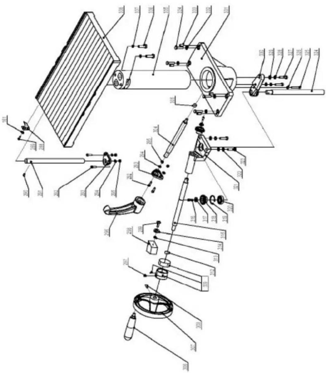
text_image
Technical diagram of a mechanical assembly with labeled parts in Chinese, showing exploded and assembled views.| Part number | Description Size Quantity | ||
| 288 | Indicator | ||
| 289 | Screw | M6x12 | 1 |
| 290 | Hex. Socket set screw M8x12 1 | ||
| 291 | Thickness table guide bar 1 | ||
| 292 | Hex. Socket cap screw M6x20 2 | ||
| 293 | Guide bar bracket 1 | ||
| 294 | Washer | H6 | 2 |
| 295 | Hex. Nut | M6 | 2 |
| 296 | Lock handle | ||
| 297 Hex socket set screw M8x12 1 | |||
| 298 | Indicator | seat | |
| 299 | Screw | M6x20 | 2 |
| 304 | Locking | bar | |
| 305 | Locking | shoe | |
| 306 | Crank | handle | |
| 307 | Crank handwheel | ||
| 308 Hex. Socket cap screw M8x10 1 | |||
| 312 | Retaining ring | CLP20 | 1 |
| 313 | Retaining ring | CLP35 | 1 |
| 314 | Washer | ||
| 315 | Crank bar | ||
| 316 | Pan head screw | M6x12 2 | |
| 317 | Washer | M6 | 2 |
| 318 | Bevel gear | ||
| 319 | Retaining ring | CLP35 | 1 |
| 320 | Bearing | BRG80202 | 1 |
| 321 | Bevel gear bracket | ||
| 322 | Washer | H8 | 8 |
| 323 | Hex. bolt | M8x35 | 8 |
| 324 | Thread rod | ||
| 325 | Hex. bolt | M6x40 | 1 |
| 326 | Hex. nut | M6 | 1 |
| 327 | Hex. bolt | M8x35 | 2 |
| 329 | Washer | H8 | 2 |
| 330 | Thread rob bracket | 1 | |
| 331 | Column support | ||
| 333 | Hex. Socket set screw | M8x20 5 | |
| 335 | Column | ||
| 336 | Hex. bolt | M10x35 | 2 |
| 337 | Spring washer | H10 | 2 |
| 338 | Thickness table | ||
| 339 | Scale ring assembly | 1 | |
Working fence assembly
Part number Description Size Quantity
368 Pin for hinge 1
369 Square nut
370 Lock nut
371 Fence mounting bracket 2
372 Hex. bolt
374 Hex. Socket cap screw M6x16 2
| 376 | Fence support-right | ||
| 377 | Nylon | washer | |
| 378 | Carriage | bolt | |
| 379 Pan head screw M6x12 6 | |||
| 380 | Washer | H6 | |
| 381 | Cutterblook | cover | |
| 382 | Lock | nut | M6 |
| 383 | Hex. Socket cap screw | M6x12 4 | |
| 384 | Fence bracket-left | ||
| 385 | Lock handle | ||
| 386 | Special washer | ||
| 387 | Fence | ||
| 388 | Fence support-left | ||
| 389 | Fence bracket-right | ||
| 390 | Fence scale | M | 1 |
| 392 | Locking tube | ||
| 393 | Screw | M8x50 | |
| 394 | Nut | M8 | 2 |
| 394A | Complete fence assembly (368-394) | 1 | |
M:
2
2
1
1
1
2

natural_image
Line drawing of a manual machine with handle and workpiece (no text or symbols)Rysunek 1
text_image
Technical diagram of a machine with labeled parts A, B, C, D and directional arrows indicating assembly or inspection.Rysunek 2
text_image
Labeled diagram of a scientific instrument with components A through H, showing internal structure and directional arrows.Rysunek 3
natural_image
Close-up of a mechanical device with labeled parts A and B, showing internal components (no readable text or symbols beyond labels)Rysunek 4
text_image
A H J W G B C D E FRysunek 7
natural_image
Industrial machine component with metal sheets and a lever mechanism (no visible text or symbols)Rysunek 9
text_image
J H D F C B D E A GRysunek 11

text_image
Technical diagram of a mechanical assembly with labeled components from A to P, showing internal components and assembly lines.Rysunek 13

natural_image
Diagram of a mechanical assembly with labeled component A, showing four components arranged around a central circular area (no text or symbols beyond label)Rysunek 14
text_image
Technical diagram of a mechanical device with labeled components and a close-up inset showing a dial indicator mechanism.Rysunek 15
natural_image
Pure mechanical assembly diagram without any text, numbers, or symbolsRysunek 16
natural_image
Technical line drawing of a mechanical assembly with a hand operating a workpiece (no text or symbols)Rysunek 17
natural_image
Technical line drawing of a wooden mechanical assembly with directional arrows indicating movement (no text or symbols)Rysunek 20
text_image
Technical diagram of a mechanical device with labeled parts A through L, showing cross-sectional and top views.text_image
Technical schematic diagram with numbered components, likely a mechanical or electrical assembly, showing various connection points and parts.text_image
Technical schematic diagram of a mechanical assembly with numbered components and labeled partstext_image
Technical schematic diagram of a mechanical assembly with numbered components and labeled partstext_image
Technical schematic diagram with numbered components and labeled parts, likely from an engineering or mechanical drawing.text_image
Technical diagram of a mechanical assembly with numbered components and labeled partstext_image
Technical diagram of a mechanical assembly with labeled parts in Chinese, showing exploded and assembled views.text_image
Technical schematic diagram with numbered components and labeled parts, likely from an engineering or mechanical drawing.natural_image
Line drawing of a manual machine with handle and workpiece (no text or symbols)Obrázek 1
text_image
Labeled diagram of a machine tool with components A, B, C, D and directional arrows indicating assembly or movement.Obrázek 2
text_image
Labeled diagram of a satellite or spacecraft system with components A through H, showing directional arrows and structural components.Obrázek 3
Napájení zařízení
natural_image
Close-up of a mechanical component with labeled parts A and B, shown from an angle (no text or symbols beyond labels)Obrázek 4
text_image
A H J W G B C D E FObrázek 7
natural_image
Industrial machine component with metal sheets and mounting bracket (no visible text or symbols)Obrázek 9
text_image
J H D F C B D E A GObrázek 11

text_image
Technical diagram of a mechanical assembly with labeled components from A to P, showing internal components and assembly lines.Obrázek 13

natural_image
Diagram of a mechanical assembly with labeled component A, showing various parts arranged in a circular layout (no text or symbols beyond label)Obrázek 14
text_image
Technical diagram of a mechanical device with labeled components and an inset view showing a dial indicator mechanism.Obrázek 15
natural_image
Pure mechanical assembly diagram without any text, numbers, or symbolsObrázek 16
natural_image
Technical line drawing of a mechanical assembly with a hand operating a component (no text or symbols)Obrázek 17
natural_image
Technical line drawing of a wooden beam being lifted by a mechanical lever (no text or symbols)Obrázek 20
text_image
Technical diagram of a satellite or radar system with labeled components from A to N, showing cross-sectional views and mechanical parts.text_image
Technical schematic diagram with numbered components, likely a mechanical or electrical assembly, showing various connection points and parts.text_image
Technical schematic diagram of a mechanical assembly with numbered components and labeled partstext_image
Technical schematic diagram of a mechanical assembly with numbered components and dimension annotationstext_image
Technical schematic diagram with numbered components and labeled parts, likely from an engineering or mechanical drawing.text_image
Technical diagram of a mechanical assembly with numbered components and labeled partstext_image
Technical diagram of a mechanical assembly with labeled parts in Chinese, showing exploded and assembled views.text_image
Technical schematic diagram with numbered components and labeled parts, likely from an engineering or mechanical drawing.natural_image
Line drawing of a manual machine with handle and workpiece (no text or symbols)Figure 1
text_image
Technical diagram of a machine with labeled parts A, B, C, D and directional arrows indicating assembly or operation.Figure 2
text_image
Labeled diagram of a scientific instrument with components A through H, showing internal structure and directional arrows.Figure 3
natural_image
Close-up of a mechanical device with labeled parts A and B, showing internal components (no readable text or symbols beyond labels)Figure 4
text_image
A H J W G B C D E FFigure 7
natural_image
Industrial machine component with metal sheets and mounting bracket (no visible text or symbols)Figure 9
text_image
J H D F C B D E A GFigure 11

text_image
Technical diagram of a mechanical assembly with labeled components from A to P, showing internal components and assembly lines.Figure 13

natural_image
Diagram of a mechanical assembly or assembly with four components arranged in a circular layout, labeled 'A' at the bottom (no text or symbols within the diagram itself)Figure 14
text_image
Technical diagram of a mechanical device with labeled components and a close-up inset showing a dial indicator mechanism.Figure 15
natural_image
Pure mechanical assembly diagram without any text, numbers, or symbolsFigure 16
natural_image
Technical line drawing of a mechanical assembly with no visible text or symbolsFigure 17
natural_image
Technical line drawing of a wooden mechanical assembly with directional arrows indicating movement (no text or symbols)Figure 20
text_image
Technical diagram of a mechanical device with labeled parts A through L, showing cross-sectional and top views.text_image
Technical schematic diagram with numbered components, likely a mechanical or electrical assembly, showing various connection points and parts.text_image
Technical schematic diagram of a mechanical assembly with numbered components and labeled partstext_image
Technical schematic diagram of a mechanical assembly with numbered components and labeled partstext_image
Technical schematic diagram with numbered components and labeled parts, likely from an engineering or mechanical drawing.text_image
Technical diagram of a mechanical assembly with numbered components and labeled partstext_image
Technical diagram of a mechanical assembly with labeled parts in Chinese, showing exploded and assembled views.text_image
Technical schematic diagram with numbered components and labeled parts, likely from an engineering or mechanical drawing.natural_image
Line drawing of a manual machine with handle and workpiece (no text or symbols)Figura 1
text_image
Technical diagram of a machine with labeled parts A, B, C, D and directional arrows indicating assembly or operation.Figura 2
text_image
Labeled diagram of a scientific instrument with components A through H, showing directional arrows and components.Figura 3
natural_image
Close-up of a mechanical device with labeled parts A and B, showing internal components (no readable text or symbols beyond labels)Figura 4
text_image
A H J W G B C D E FFigura 7
natural_image
Close-up of a metallic mechanical assembly with no visible text or symbolsFigura 9
text_image
J H D F C B D E A GFigura 11

text_image
Technical diagram of a mechanical assembly with labeled components from A to P, showing internal components and assembly lines.Figura 13

natural_image
Diagram of a mechanical assembly or assembly with labeled component A, showing multiple components arranged in a circular layout (no text or symbols beyond label)Figura 14
text_image
Technical diagram of a mechanical device with labeled components and a close-up inset showing a circular component.Figura 15
natural_image
Pure mechanical assembly diagram without any text, numbers, or symbolsFigura 16
natural_image
Technical line drawing of a mechanical assembly with a hand operating a workpiece (no text or symbols)Figura 17
natural_image
Technical line drawing of a wooden mechanical assembly with directional arrows indicating movement (no text or symbols)Figura 20