WOOB-4002000 - Woodworking machine MSW - Free user manual and instructions
Find the device manual for free WOOB-4002000 MSW in PDF.

User questions about WOOB-4002000 MSW
0 question about this device. Answer the ones you know or ask your own.
Ask a new question about this device
Download the instructions for your Woodworking machine in PDF format for free! Find your manual WOOB-4002000 - MSW and take your electronic device back in hand. On this page are published all the documents necessary for the use of your device. WOOB-4002000 by MSW.
USER MANUAL WOOB-4002000 MSW
COMBINED WOOD WORKING MACHINE
| DE | Produktname | Kombimaschine |
| EN | Product name | Combined wood working machine |
| PL | Nazwa produktu | Maszyna wielofunkcyjna do obróbki drewna |
| CZ | Název výrobku | Kombinovaný dřevoobráběcí stroj |
| FR | Nom du produit | Machine combinée pour le travail du bois |
| IT | Nome del prodotto | Macchina combinata per la lavorazione del legno |
| ES | Nombre del producto | Máquina combinada para trabajar la madera |
| HU | Termék neve | Kombinált famegmunkáló gép |
| DA | Produktnavn | Kombineret træbearbejdningsmaskine |
| FI | Tuotteen nimi | Yhdistetty puuntyöstökone |
| NL | Productnaam | Gecombineerde houtbewerkingsmachine |
| NO | Produktnavn | Kombinert trebearbeidingsmaskin |
| SE | Produktnamn | Kombinerad träbearbetningsmaskin |
| PT | Nome do produto | Máquina combinada para trabalhar madeira |
| SK | Názov produktu | Kombinovaný drevoobrábací stroj |
| BG | Име на продукта | Комбинирана дървообработваща машина |
| EL | Όνομα προϊόντος | Συνδυασμένη μηχανή επεξεργασίας ξύλου |
| HR | Naziv proizvoda | Kombinirani stroj za obradu drva |
| LT | Produkto pavadinimas | Kombinuota medienos apdirbimo mašina |
| RO | Numele produsului | Maşină combinată pentru prelucrarea lemnului |
| SL | Ime izdelka | Kombinirani stroj za obdelavo lesa |
| DE Modell | EN Product model | PL Model produktu | CZ Model výrobku | FR Modèle | IT Modello | ES Modelo | HU Modell | DA Model | FI Tuotteen malli | NL Productmodel | NO Produktmodell | SE Produktmodell | PT Modelo do produto | SK Model | BG Модел на продукт | EL Movtéλo προϊόντος | HR Model proizvoda | LT: Gaminio modelis | RO: Model de produs | SL: Model izdelka | MSW-WOOB-4002000 | |
| DE Hersteller | EN Manufacturer | PL Producent | CZ Výrobce | FR Fabricant | IT Produttore | ES Fabricante | HU Termelő | DA Producent | FI Valmistaja | NL Producent | NO Produsent | SE Tillverkare | PT Fabricante | SK Výrobca | BG Производител | EL Κατασκευαστής | HR Proizvođač | LT Gamintojas | RO Producător | SL Proizvajalec | expondo Polska sp. z o.o. sp. k. | |
| DE Anschrift des Herstellers | EN Manufacturer Address | PL Adres producenta | CZ Adresa výrobce | FR Adresse du fabricant | IT Indirizzo del produttore | ES Dirección del fabricante | HU A gyártó címe | DA Producentens adresse | FI Valmistajan osoite | NL Adres producent | NO Produsentens adresse | SE Tillverkarens adress | PT Endereço do fabricante | SK Adresa výrobcu | BG Адрес на производителя | EL: Διεύθυνση κατασκευαστή | HR Adresa proizvođača | LT Gamintojo adresas | RO Adresa producătorului | SL Naslov proizvajalca | ul. Nowy Kisielin – Innowacyjna 7, 66-002 Zielona Góra | Poland, EU | |

natural_image
Technical line drawing of a mechanical machine with no visible text or symbolsnatural_image
Technical line drawing of a mechanical assembly with gears and shafts (no text or symbols)natural_image
Technical line drawing of a mechanical device with rollers and mounting brackets (no text or symbols)1- 13er-Schlüssel
2- Spezial-Schlüssel
natural_image
Line drawing of hands using a tool to cut or mark a piece of material on a workbench (no text or symbols)natural_image
Close-up of a white mechanical device on a perforated metal tray, with a hand partially visible (no text or symbols)Querschneiden
natural_image
Close-up of a mechanical assembly with a white panel and metal frame (no visible text or symbols)Abgeschrägte Kante
natural_image
Industrial robotic arm operating a metal frame with a curved handle (no visible text or symbols)Diagonalanschlag
natural_image
Two technical diagrams showing mechanical assembly with arrows indicating direction, no text or symbols presentnatural_image
Technical line drawing of a mechanical assembly with labeled components A and B (no text or symbols beyond labels)
natural_image
Line drawing of a hand operating a mechanical tool or device (no text or symbols present)Abbildung 2
1- Kutter
2- Schnittkreis
3- Hinterer Zaun
4- Vorderer Zaun
Abbildung 4
1- Kragen
2- Kutter
natural_image
Illustration of hands using a tool on a wooden surface, with arrows indicating motion direction (no text or symbols)natural_image
Illustration of a hand using a wooden plank to cut a saw, with an inset showing mechanical components (no text or symbols)natural_image
Illustration of hands using a tool to work on a grid-patterned object, no text or symbols presentnatural_image
Line drawing of hands using a tool to cut or install a metal bracket (no text or symbols)Abbildung 11
Abbildung 14
natural_image
Pure mechanical diagram showing a lever mechanism without any text, numbers, or symbolsnatural_image
Technical line drawing of a hand operating a wooden plank with a tool, no text or symbols presentAbbildung 16
natural_image
Technical line drawing of a wooden cutting tool with directional arrows indicating movement (no text or symbols)natural_image
Technical line drawing of a mechanical assembly with hands operating a tool (no text or symbols present)natural_image
Close-up of a cylindrical mechanical component with a red arrow pointing to a hole (no visible text or symbols)natural_image
Close-up of a mechanical component with a cylindrical shaft and circular base, featuring a red arrow pointing to a specific part (no text or symbols visible)natural_image
Close-up of a mechanical component with a bolted head and flange, showing no visible text or symbols.natural_image
Close-up of a mechanical component with red arrows pointing to features, no visible text or symbolsnatural_image
Close-up of a metallic mechanical component mounted on a circular base, with no visible text or symbols.Abbildung 21

This User Manual has been translated using machine translation. We have made every effort to ensure the translation is accurate, but please note that automated translations are not perfect and are not meant to replace human translators. The official version of the User Manual is in English. Any differences between the translated version and the original English are not legally binding. If you have any questions about the accuracy of the translation, please refer to the English version, which is the official reference. More language versions are available upon request via info@expondo.com.
Technical data
| Parameter description Parameter value | |
| Product name Combined wood working machine | |
| Model | MSW-WOOB-4002000 |
| Rated voltage [V~, N] / frequency [Hz] 400, 3 / 50 | |
| IP | 20 |
| Dimensions [width * length * height; mm] 1520*2260*1090 | |
| Weight [kg] 395 | |
| Panel saw | |
| Rated power [W] 2200 | |
| Rotation speed [/min] 4000 | |
| Blade dia. [mm] 254 | |
| Blade bore [mm] 30 | |
| Table size [mm] 680*530 | |
| Sliding table size [mm] 1320*238 | |
| Cutting capacity [mm@°] 78@90, 63@45 | |
| Planer & thicknesser | |
| Rated power [W] 2200 | |
| Cutter block speed [/min] 5500 | |
| Knife size [mm] | 260*25*3 |
| Planer | |
| Cutting capacity [mm] | 3 |
| Table size [mm] | 1090*260 |
| Thicknesser | |
| Cutting capacity [mm] | 4 |
| Table size [mm] 545*258 | |
| Max height [mm] | 225 |
| Feed speed [m/min] | 7 |
| Spindle moulder | |
| Rated power [W] 1500 | |
| Milling speed [/min] | 1400/4000/6000/9000 |
| Spindle [mm] | 30 |
| Max cutter [mm] | 160 |
| Milling travel [mm] | 0-105 |
Description
natural_image
Technical line drawing of a mechanical machine assembly (no text or symbols visible)The product enables lengthwise as well as crosswise cutting and moulding with a vertical spindle of semi-finished products made of wood or of materials based on wood or the combined five-operation woodworking machine enabling lengthwise and crosswise cutting and moulding with a vertical spindle, planing and thicknessing of semi-finished products made of wood or of materials based on wood.
The machine is designed for operation performed by one worker only.
The user is liable for any damage resulting from unintended use of the device.
Specifications concerning the noise of the device
| Level of noise A in place of operation (LpAeq) | No-load | Laiq =81.7 dB(A) |
| Load | LpAeq =89.5 dB(A) | |
| Level of acoustic power A (LWA) | No-load | L_WA = 94.5 dB(A) |
| Load | L_WA = 103 dB(A) |
Operating conditions for noise measurement comply with annex B of ISO 7960. The values given are those of emissions and do not necessarily mean any safe working values. Although there is a correlation between the value of emissions and the levels of exposure, these values cannot be used for a reliable determination whether additional measures are necessary. The factors influencing actual levels of workers' exposure include the properties of the working area, other sources of noise, etc., e.g. the number of machines and the other neighboring procedures. Also, the highest permissible levels of exposure may vary in different countries. This information should help the machine user to evaluate the risk and the risk rate in a better manner.
Installation
Connection of the exhaustion system
Work on the machine only with the exhaustion system connected and running! For the proper functioning of the machine, exhaustion equipment with minimum exhaustion capacity of 570m^3/ hour and minimum speed of
air in the pipes equal to 20m/s for dry particles and 790 m ^3 /hour and minimum speed of air in the pipes equal to 28m/s for wet particles is necessary.
Switch on the machine drive and exhaustion system at the same time!
Use flexible exhausting hoses with diameters equal to 100 mm and 32 mm. The exhausting hoses are connected to exhausting outlet whose location on individual machines is as follows:
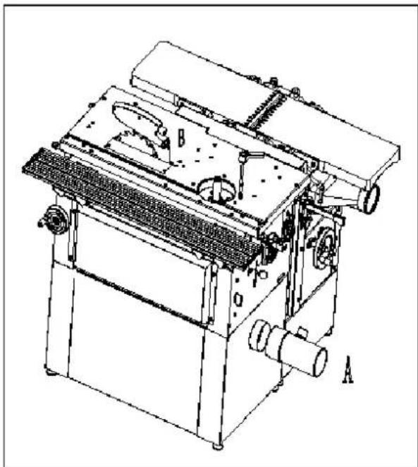
Circular saw
natural_image
Technical line drawing of a mechanical machine with labeled parts A and B (no text or symbols beyond labels)The upper exhaustion unit from the circular saw is connected to the outlet located on the disc cover.
The diameter of outlet (B) is 32 mm.
The bottom exhausting unit is led out on the lower rear part of the machine (A).
The exhausting hose diameter is 100 mm.
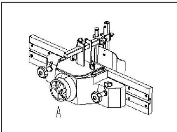
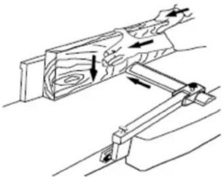
Vertical moulding machine
natural_image
Technical line drawing of a mechanical assembly with gears and shafts (no text or symbols)For the moulding machine the exhausting hose is fitted onto the outlet from the moulding tool cover which also forms the exhausting connector (A). The hose diameter is 100 mm.
Planing machine
The planing machine has the exhaustion outlet in the space of the thicknessing machine under the planing table.
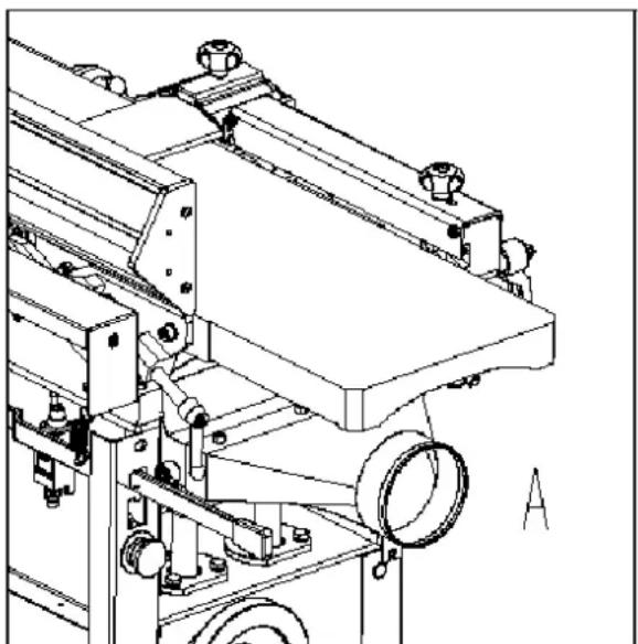
Thicknessing machine
natural_image
Technical line drawing of a mechanical device with rollers and mounting brackets (no text or symbols)The thicknessing machine uses the same exhausting outlet as that for planing, but turned to the upper position.
The diameter of the outlet for connection of exhaustion hose (A) is 100 mm.
Connection to the mains
- Damaged power supply cables must be replaced by a competent specialist immediately. Operation with damaged cables is dangerous to life and is therefore forbidden!
- Before putting the machine into operation make sure that the voltage and frequency specified on the machine type plate comply with the values of the mains to which it is connected.
• Over voltage protection shall be provided by the end user. - Before adjustment and replacement of tools and before any adjustment work, alterations and maintenance work, always turn off the switch and disconnect the plug from supply socket.
- This machine must be connected to the protection earth. Inspect and be sure that the socket is reliably earthed.
Direction of rotation
If you are standing on the side of the machine at the sliding table, the saw disc must rotate anti-clockwise. Cutter block of the planing and thickening machine rotates anti-clockwise too. The moulder spindle rotates anticlockwise if you look down.
Operation
Preparation
Remove the protective coating from the working tables and other parts of the machine either with paraffin oil or any similar solvent, do not use petrol or similar solvents for this activity –they might cause reduced corrosion resistance of certain parts of the machine.
The working area size depends on the type of the machine, assumed working operations and size of material machined.
Do not forget about the space for location of a sufficiently effective exhausting system or connecting hoses for the central exhaustion.
Workers' qualifications
Only an expert skilled in the field of wood-machining or a worker instructed and trained by such expert may operate the machine, regardless of the gender. While working on the machine the operator must get familiar with these instructions and comply with any safety rules, regulations and provisions in force in the respective country.
Working environment
The machine must be operated in a workshop environment the temperature of which does not exceed +40°C and does not drop below +5°C. The relative humidity of ambient is from 30% to 95%, non-condensing. The height above the sea level is up to 1000 m.
Storage and transportation temperature: -25\~+55°C
The environment classification - danger of inflammable dust fire.
Working area
It is important to maintain free area of 0.8 m around the machine, which is required for the working place. If any long material is machined, it is necessary to have a sufficient room in front of the machine as well behind it in the places of material input and output.
Operation and adjustment of the machine
Adjustment should be only made when the saw is in standstill.
Remove the table insert
Block the spindle with current sawing tool; remove the flange (thoroughly clean when reassembling).
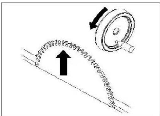
Note the direction of the teeth when replacing the saw blade. Replace the various connection elements
1- 13-wrench
2- Special spanner
Loosen the flange base with a 13 mm wrench and insert the splitting wedge. Adjust the splitting wedge and be sure to maintain a distance of approx. 3mm to the saw blade. Securely fasten the splitting wedge with screw. Check that the splitting wedge is parallel to the saw blade by means of the table insert.
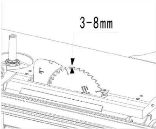
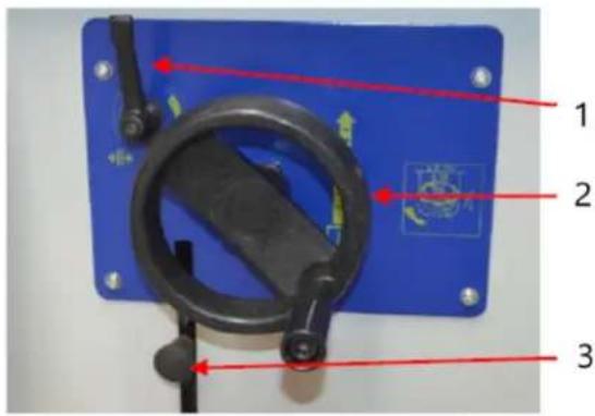
Height setting
The height of the main saw disc is adjusted by turning the hand wheel. The screw is self-locking and does not require any securing.
Rotation to the right = height -
Rotation to the left = height +
The cutting height is always adjusted "from below" so that possible clearance may be eliminated. The cutting height is usually selected so that the saw disc teeth project from the workpiece.
Saw disc tilting
The saw disc may be tilted to the side by up to 45^ by turning the hand wheel.
Turning to the right = 0° to 45°
Turning to the left =45° to 0°
At the same time, the scale indicator upon the height adjusting wheel is decisive. After the tilting is adjusted, tighten the fixing lever again.
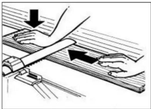
natural_image
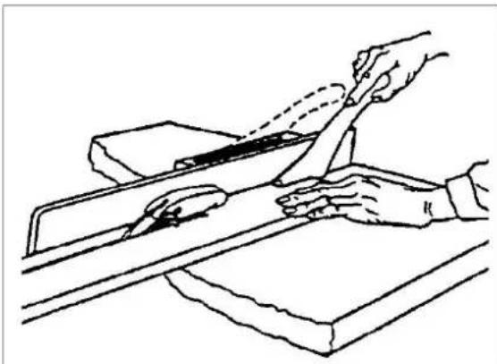
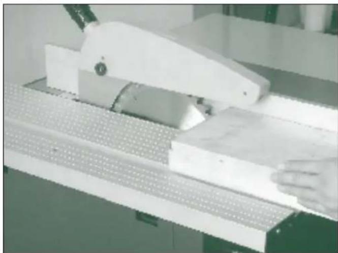
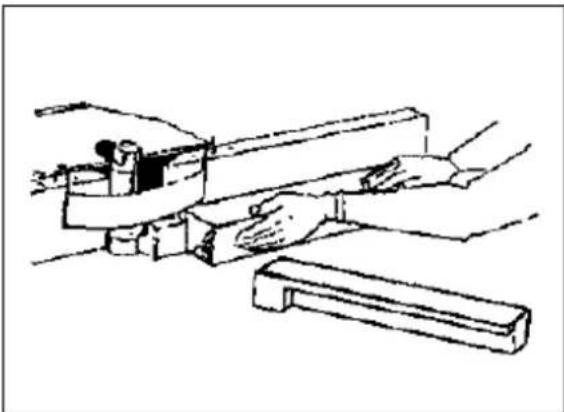
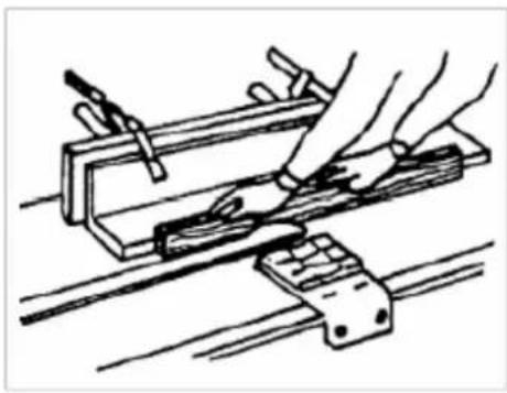
Line drawing of hands using a tool to cut or mark a piece of material on a workbench (no text or symbols)While a workpiece wide less than 120 mm is being cut lengthwise, a pusher (included in the machine accessories) must be used to shift the workpiece.
Basic applications
Ripping
When the timber is cut with the grain, use the rip fence for this application
natural_image
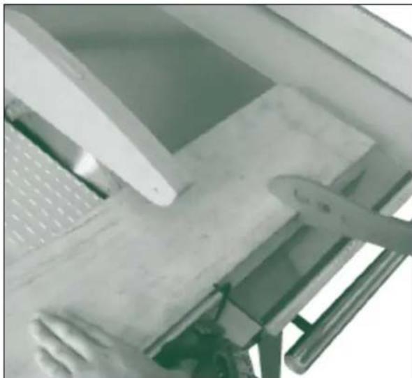
Close-up of a white mechanical device with a wooden base and perforated panel, no visible text or symbolsCross cutting
When the timber is cut across the grain, use either mitre fence or sliding carriage for this application.
natural_image
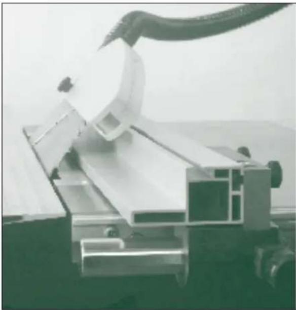
Close-up of a white computer monitor with a keyboard and mouse, no visible text or symbolsBevelled edge
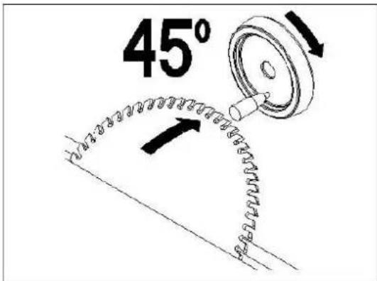
When a bevelled (angled) edge is required to the workpiece tilt the blade and pass the timber though. If the rip fence is being used with the blade is tilted the auxiliary fence should be used in the low position to prevent it fouling on the blade when tilted.
natural_image
Industrial robotic arm handling metal components (no visible text or symbols)Diagonal limit stop
The diagonal limit stop can be mounted on the left or right hand side of the saw blade in the T-groove.
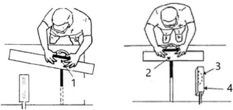
1- Lock mitre gauge and hold work firmly
2- Workpiece held firmly
3- Blade set at angle less than so degrees for bevel cut
4- Guard
Blade selection
Before undertaking any application on a table saw is important to consider blade selection. There are many blade types available, and it is important to select the right blade for the job. The machine is supplied with a good multi-purpose blade, but for specialist applications a blade with a different tooth pattern may be required.
A table saw can be fitted with two different styles of blade: An alternative bevel blade or a triple chip tooth blade. See table 2 for applications.
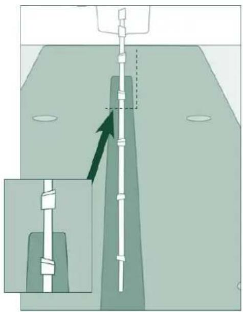
natural_image
Diagram showing a vertical pipe or tube inserted into a container with an inset magnified view (no text or symbols)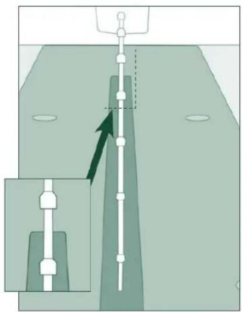
natural_image
Diagram showing a mechanical assembly with a vertical rod and a magnified inset view (no text or symbols)Operation and adjustment of the Mill
Set the height of the moulding spindle by means of the hand wheel located on the rear right side of the stand and secure it with the arresting screw. Select the suitable filler of the table (table ring) according to the tool used.
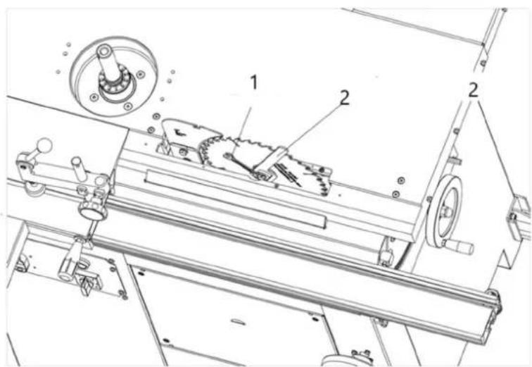
Speed change
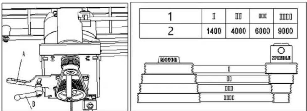
1- Speed step
2- Speed (RPM)
This moulder is equipped with pulleys that allow you to change the spindle speed. The belt placed on the upper pulleys as shown in position I provides a 1400 RPM spindle speed. To change the spindle speed, loosen the lock handle (A) and pivot the motor assembly toward the spindle. Reposition the belt to the desired speed and tension the knob(B).
Lengthwise moulding
1- Infeed fence
2- Locking knob
3- Pressure pad
4- Outfeed fence
5- Fine adjusting handle
Tool: use suitable tools with a defined thickness of the chip for manual feeding.
Working cycle: while test moulding is being performed, start working with a workpiece with sufficient length, width and height. It is necessary to prevent blocking of the machine, or to use a security against kick-back adapted to the workpiece dimensions. In order to prevent kickback, it is necessary to use back and/or front end stops fixed to the fence, table or fixed to and extension table.
Never set the rulers while the machine is being operated!
While working, perform the lateral adjustment of the fence plates, keep the opening for the tool to be reduced
to a minimum, lock the fence plates and adjust the fine adjusting handle to set the required chip (wood removal) and lock the station by the locking knob.
Keep the pressure pads in contact with the table and the fence plates firmly
and evenly along the guide ruler.
The cutting speed shall exceed 40 m s^-1 to lessen the risk of kickback but shall not exceed 70 m s^-1 in order to lessen the risk of tool damage.
Adequate general or localized lighting shall be provided.
Moulding of workpieces with small cross-section
Tool: Choose the tool suitable for manual feeding.
natural_image
Line drawing of a hand operating a mechanical tool or device (no text or symbols present)Working cycle: Adjust the moulding machine and put both halves of the ruler close to the tool. Machine the material only by means of a pusher! Choose the size of the pusher so that the hand may be put on it comfortably.
Protective aids
For work on the machine eye protection are prescribed. It is advisable to use appropriate ear protection and commended working shoes. Working overall coats are not allowed to use.
Handlings NOT allowed
On the machine, it is NOT allowed to:
• perform any alteration of the machine safety items without the manufacturer's permission.
• perform any manipulation inconsistent with safety instructions in this handbook.
- touch the tool or its close surrounding places and other moving parts.
• machine any materials other than wood or those based on wood.
• overload the machine while machining large semi-finished products.
- remove chips from the place near the tools by hand or with any object while the machine is being operated.
• use other tools than those delivered or recommended by the machine manufacturer.
Using the Fence as a Guide
Shaping with the fence is the safest and most satisfactory method of working. This method should always be used when work permits. Almost all-straight work can be used with the fence.
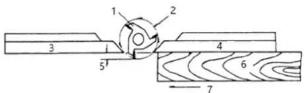
Figure 1
1- Cutter
2- Cutting circle
3- Rear fence
4- Front fence
5- Depth of cut
6- Work
7- Feed
- For most work, where a portion of the edge of the work is not touched by the cutter, both the front and rear fences are in a straight line, as shown in figure 1.
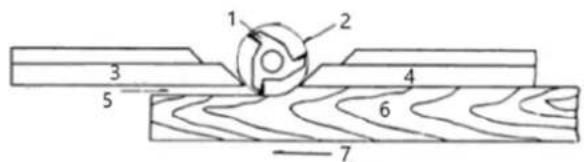
Figure 2
1- Cutter
2- Cutting circle
3- Rear fence
4- Front fence
5- No support
6- Work
7- Feed
- When the shaping operation removes the entire edge of the work (i.e. jointing or making a full bead), the shaped edge will not be supported by the rear fence when both fences are in line as shown in figure 2. In this case, the workpiece should be advanced to the position shown in figure 2 and stopped.
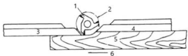
Figure 3
1- Cutter
2- Cutting circle
3- Rear fence
4- Front fence
5- Work
6- Feed
- The front fence should be advanced to contact the work as shown in figure 3. The rear fence will then be in line with the cutting circle.
Shaping with Collars
Follow these rules when shaping with collars for the safest operation and best results:
-
Collars must be smooth and free from all gum or other substances.
-
The edge of the work must be smooth. Any irregularity in the surface, which rides against the collar, will be duplicated on the shaped surface.
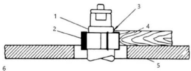
Figure 4
1- Collar
2- Cutter
3- Not sufficient bearing surface
4- Work
5- Table
6- Wrong
- A portion of the work's edge must remain untouched by the cutter so that the collar will have sufficient bearing surface. See figure 4 for an example of insufficient bearing surface.
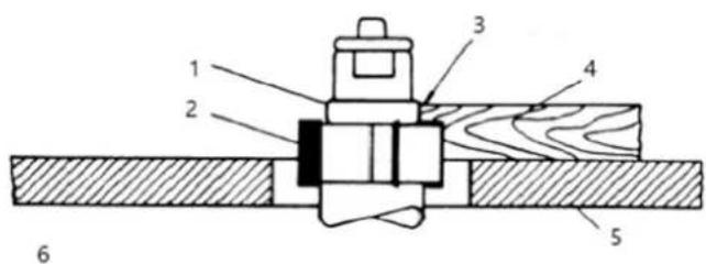
Figure 5
1- Collar
2- Cutter
3- Sufficient bearing surface
4- Work
5- Table
6- Right
4. Figure 5 illustrates sufficient bearing surface.
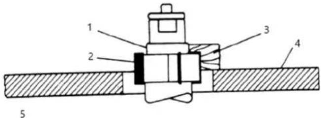
Figure 6
1- Collar
2- Cutter
3- Narrow workpiece
4- Table
5- Wrong
5. Under no circumstances should a small workpiece be shaped against the collars as shown in figure 6.
Collar Positioning
Collars may be positioned above, below, or between two cutters:
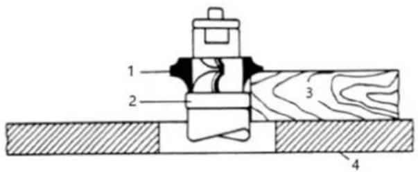
Figure 7
1- Cutter
2- Collar
3- Work
4- Table
1. When using the collar below the cutter, figure 7, the progress of the cut can be observed at all times. A disadvantage of this method is any accidental lifting of the work will gouge the wood and ruin the
workpiece.
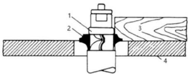
Figure 8
1- Collar
2- Cutter
3- Work
4- Table
- Using the collar above the cutter, figure 8, offers the advantage of the cut not being affected by slight variations in the stock's thickness. However, the cut is not visible during the operation. Another advantage is accidental lifting of the work piece will not gouge the work piece. Simply correct the mistake by repeating the operation.
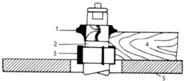
Figure 9
1- Cutter
2- Collar
3- Cutter
4- Work
5- Table
- The collar between cutters method, shown in figure 9, has both the advantages and disadvantages of the first two methods. This method is used primarily where both edges of the work are to be shaped.

NOTICE! The machine cannot be used for tenoning!
Adjustment of the planing machine
Adjustment and operation of the protective device
The height setting of cutter block (A) is performed by means of a screw with star head (C).
Turning to the right – the cover height is increased
Turning to the left— the cover height is decreased
When you release the other star-like screw (B), you may easily move the cover of the cutter block in the lengthwise direction. After the setting tighten the star-like screw. When screw (D) is released, the ruler may be put out of the working position. While planing height pieces, set the shaft so that its end is at the maximum distance of 5 mm from the machined piece.
Planing
Adjustment of the movable table – setting of the chip thickness:
• release the table by means of the fixing lever on the right side
• set the required chip (wood removal) by means of the hand star on the left side
- secure the table by means of the fixing lever
• the size of the chip setting may be read on the scale
Adjustment of the tilting ruler:
- release the star-like screw of the rule guiding
• adjust the ruler to the value of the machined workpiece width
• tighten the star-like screw firmly again
Switch off the drive of the feeding rollers for thicknessing by means of a hand lever at the input of thicknessing machine – push the lever downwards and secure it in the lower position.
Planing of flat pieces
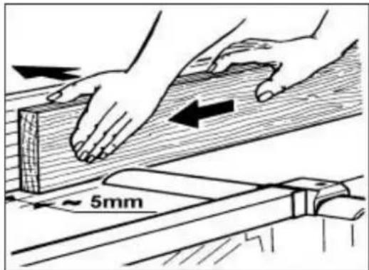
natural_image
Illustration of hands using a tool on a wooden surface, with arrows indicating motion direction (no text or symbols)Put the flat piece on the planing table, lift the cover of the cutter block by left hand to the required height and switch on the machine. Press and shift it over the cutter block, the hand moves above the cover. The material is moved by arms, not by the body! You must not move the machined piece backwards over the cutter block!
Planing of high pieces
While machining the high pieces adjust the cover of the cutter block so that the gap between the machined piece and the cover is 5mm at most. Switch on the machine and press the machined piece and shift it over the cutter block between the cover and the ruler.
Planing with the ruler titled
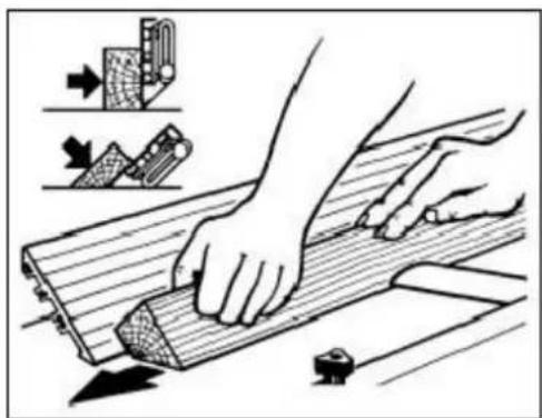
natural_image
Illustration of hands using a wooden plank to cut or slide, with tool icons and arrows indicating process (no text or symbols)Try to adjust the ruler tilting angle with released fixing levers (position 90^ is secured), tighten the levers and switch on the machine. Press the beveled machined piece to the ruler and forwards.
Planing of short pieces
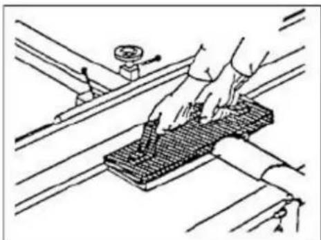
natural_image
Technical line drawing of a hand using a tool to adjust or install a grid-patterned component on a mechanical assembly (no text or symbols)While planing short pieces, you should use a pusher. A possible design is shown in the figure.
The pusher may be ordered as a special accessory to the machine.
Planing of pieces with a small cross-section
natural_image
Line drawing of hands using a tool to work on a metal frame (no text or symbols)High risk of injury if guided along the ruler improperly.
The ruler must be supplemented with an auxiliary ruler for planing of thin materials. It must be wider than 60 mm of a height 20-25 mm.
Jointer to Planer Setup
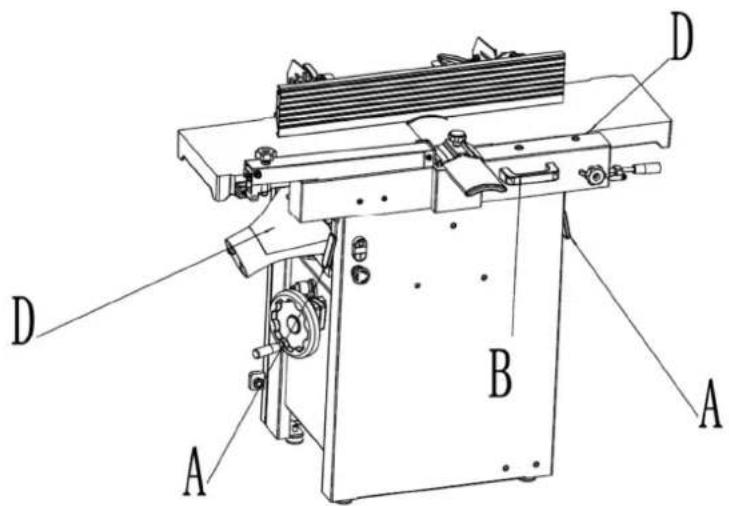
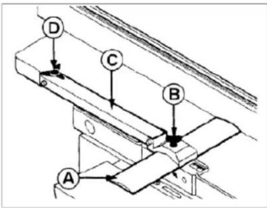
Figure 10
Referring to figure 10. To change the machine configuration jointer to planer:
-
Release both cabinet table locks (A) by rotating the handles toward the operator, then pulling away from the machine.
-
Raise the table (C, figure 11) using the handle (B).
Table is heavy. Use care when raising. Failure to comply may cause serious injury.
When raised, the table should be in the vertical position as shown in C, figure 4. The latch (E, figure 11) should be engaged, preventing the table from an accidental forward fall.
- Position the dust chute (D, H, figure 11) to the right. Use extreme care to avoid contact with cutterhead knives.
Note: The planer table may need to be lowered to allow clearance needed to position the dust chute.
Planer to Jointer Setup
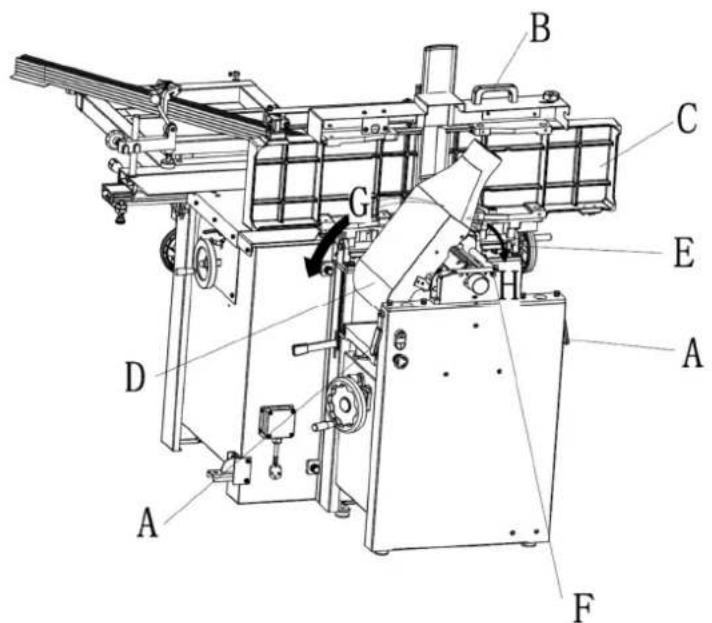
Figure 11
Referring to figure 11. To change the machine configuration from planer to jointer:
- Pull the release knob (F) and reposition the dust chute (D, G) to the left. It should be positioned as shown in D.
Table is heavy. Use care when lowering. Failure to comply may cause serious injury.
-
Release the latch (E) and bring the table forward using the tilt handle (B). It should be positioned as shown in C.
-
Lock the table (C) by pushing the lock handles (A) in toward the machine and rotating down (away from the operator).
Planer Controls and Adjustments
Referring to Figure 12:
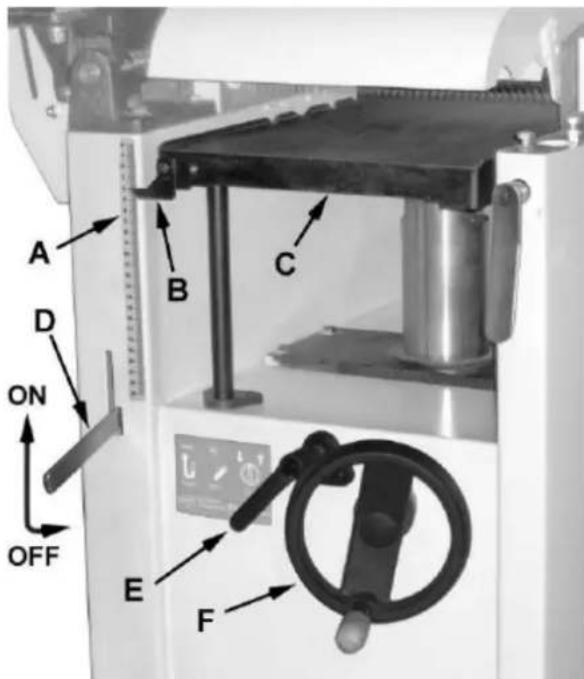
Figure 12
Power Feed
Placing the planer power feed handle (D) in the up position turns the planer power feed on (see arrow). Placing the handle in the down position turns the power feed off.
Table Lock
Turn the table lock (E) clockwise to lock the height adjustment handwheel (F) and secure the planer table (C) in its selected position. Turn the table lock (E) counterclockwise to release and permit table adjustment.
Table Height Adjustment
The planer table height is set as follows:
- Unlock the table lock (E).
- Rotate the height adjustment handwheel (F) clockwise to raise the planer table (C), counterclockwise to lower.
- Lock the table lock (E). Each revolution of the handwheel (F) results in a 4 mm up or down movement of the table (C). A scale on the handwheel column indicates the amount of handwheel rotation. A pointer (B) indicates the table position relative to the cutterhead on the scale (A) located on the side of the cabinet.
Jointer Controls and Adjustments
Referring to Figure 13:
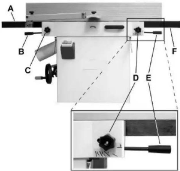
Figure 13
Outfeed Table Height Adjustment
The lock knob (C) and lifting handle (B) control the height adjustment of the outfeed table (A). The outfeed table is initially adjusted at the factory and should not be repositioned except during certain adjustments.
Infeed Table Height Adjustment
Lock knob (D) and lifting handle (E) control the height adjustment of the infeed table (F). To adjust:
- Loosen lock knob (D).
- Raise the lifting handle (E) to raise the infeed table for a shallow depth of cut. Lower the handle for a deeper cut.
- Tighten the lock knob (D).
Note: A depth of cut of 1.5mm or less is recommended.
Cutterhead Guard
Properly positioned, the cutterhead guard (H) should rest against the fence (A).
Fence Movement
Referring to Figure 14:
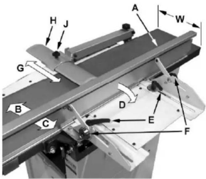
Figure 14
The fence (A) can be moved forward (B) or backward (C) across the width (W) of the table. It also tilts up to 45 degrees backwards (D). Loosen the lock knob (J), slide the guard into position, then tighten the lock knob.
To slide the fence forward or backward:
When edge jointing, the fence assembly should periodically be moved to different positions to distribute wear on the cutterhead knives. This is done as follows:
- If necessary, loosen the cutterhead guard (H) to permit the fence assembly to move freely without being constrained by the guard.
- Loosen two fence assembly locking handles (E).
- Move the entire fence assembly to the desired position; then re-tighten the handles (E).
- Readjust and secure the cutterhead guard.
To tilt the fence backward: The fence (A) can be tilted backward (D) up to 45^ (that is, for a total included angle of 135^ from table surface) as follows:
- Loosen locking handles (F).
- Tilt the fence back (A, C) to the desired angle up to 135^ . Or you can place your bevelled reference piece on the table and against the fence, adjusting the fence until the angle of the fence matches the bevel of your gauge piece.
- Tighten the locking handles (F).
- Readjust and secure the cutterhead guard.
Basic Operations
Dust Collection
Before initial operation, the machine must be connected to a dust collector.
Initial Startup
After the assembly and adjustments are complete the planer is ready to be tested. Turn on the power supply at the main panel. Press the Start button. Keep your finger on the Stop button in case of a problem. The planer should run smoothly with little or no vibration or rubbing noises. Investigate and correct the source of any problems before further operation.
DO NOT attempt to investigate or adjust the planer while it is running.
Wait until the planer is turned off, unplugged and all working parts have come to a complete standstill.
Changing Mode of Operation
When changing the operating mode (planer to jointer and back) the machine must be turned off and at a complete standstill. To change the mode of operation, see the sections "Jointer to Planer Setup" and "Planer to Jointer Setup".
Jointer Operations
Correct operating position
The operator must be positioned offset to the infeed table (Figure 15).
natural_image
Pure mechanical assembly diagram without any text, numbers, or symbolsFigure 15 Hand placement
Referring to Figure 15:
At the start of the cut, the left hand holds the workpiece firmly against the infeed table and fence while the right hand pushes the workpiece in a smooth, even motion toward the cutterhead. After the cut is under way, the new surface rests firmly on the outfeed table. The left hand is transferred to the outfeed side (Figure 16) and presses down on this part of the workpiece, at the same time maintaining flat contact with the fence. The right hand presses the workpiece forward and before the right hand reaches the cutterhead it should be moved to the work on the outfeed table.
Surfacing

natural_image
Technical line drawing of a wooden frame with a hand operating a lever mechanism (no text or symbols)Figure 16
The purpose of planing on a jointer is to produce one flat surface (Figure 16). The other side can then be milled to precise, final dimensions on a thickness planer resulting in a board that is smooth and flat on both sides and each side parallel to the other.
- If the wood to be jointed is cupped or bowed, place the concave side down, and take light cuts until the surface is flat.
- Never surface pieces shorter than 12 inches or thinner than 3/8 inch without the use of a special work holding fixture.
• Never surface pieces thinner than 3 inches without the use of a push block. - Cuts of approximately 1/16" at a time are recommended, which provides for better control over the material being surfaced. More passes can then be made to reach the desired depth.
Direction of Grain
Avoid feeding work into the jointer against the grain (Figure 17).
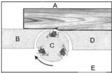
Figure 17
A- Against the grain
B- Outfeed table
C- Cutterhead
D- Infeed table
E- Wrong
This may result in chipped and splintered edges. Feed with the grain to obtain a smooth surface, as shown in Figure 18.
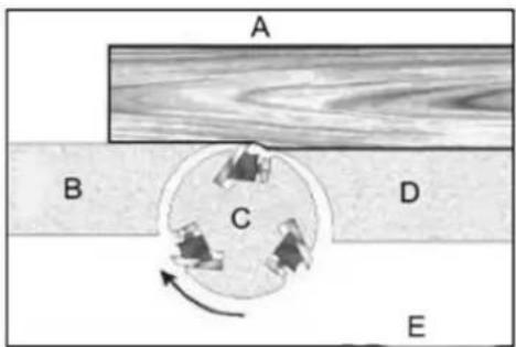
Figure 18
A- With the grain
B- Outfeed table
C- Cutterhead
D- Infeed table
E- Correct
Jointing
natural_image
Technical line drawing of a wooden cutting tool with directional arrows indicating movement (no text or symbols)Figure 19 Surfacing
Jointing (or edging) is the process of creating a finished, flat edge surface that is suitable for joinery or finishing (Figure 19). It is also a necessary step prior to ripping stock to width on a table saw.
- Never edge a board that is less than 3 inches wide, less than 1/4 inch thick, or 12 inches long, without using a push block.
- When edging wood wider than 3 inches lap the fingers over the top of the wood, extending them back over the fence such that they will act as a stop for the hands in the event of a kickback.
• Position the fence (move forward) to expose only the amount of cutterhead required.
When workpiece is twice the length of the jointer infeed or outfeed table use an infeed or outfeed support.
To edge:
- Make sure the fence is set to 90°. Double check it with a square.
- Inspect stock for soundness and grain direction (refer to Direction of Grain on previous page).
- If the board is bowed (curved), place the concave edge down on the infeed table.
- Set the infeed table for a cut of approximately 1.5mm.
- Hold the stock firmly against the fence and table, feed the stock slowly and evenly over the cutterhead.
Bevelling
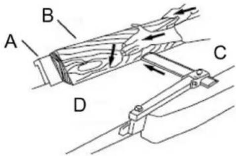
Figure 20
A- Fence
B- Stock
C- Infeed table
D- Outfeed table
Bevelling an edge is the same operation as edge jointing, except that the fence is tilted to a specified angle.
Make certain the material being bevelled is over 12 inches long, more than 1/4 inch thick and 1 inch wide.
To bevel:
- Use a bevel gauge to determine the desired angle. Then set the fence to the same angle.
- Inspect stock for soundness and grain direction (refer to Direction of Grain on previous page).
- Set the infeed table for a cut of approximately 1.5mm.
- If the board is bowed (curved), place the concave edge down on the infeed table.
- Feed the stock through the cutterhead, making sure the face of the stock is completely flat against the fence and the edge is making solid contact on the infeed and outfeed tables (Figure 20).
For wood wider than 3 inches – hold with fingers close together near the top of the stock, lapping over the board and extending over the fence. For wood less than 3 inches wide – use bevelled push blocks and apply pressure toward the fence. Keep fingers near top of the push block. Several passes may be required to achieve the full bevel will probably take several passes.
Planer Operations
Depth of Cut
Thickness planing refers to the sizing of lumber to a desired thickness while creating a level surface parallel to the opposite side of the board. Board thickness that the planer will produce is indicated by the scale and the depthof - cut gauge. Preset the planer to the desired thickness of the finished workpiece using the gauge. The depth-of-cut is adjusted by raising or lowering the planer table (C, Figure 12) using the handwheel (F, Figure 12).
• The quality of thickness planning depends on the operator's judgment about the depth of cut.
- The depth of cut depends on the width, hardness, dampness, grain direction and grain structure of the wood.
- The maximum thickness of wood that can be removed in one pass is 1/8" for planning operations on workpieces up to 5-1/2" wide. The workpiece must be positioned away from the center tab on the rollercase to cut 1/8".
- The maximum thickness of wood that can be removed in one pass is 1/16" for planning operations on workpieces from 5-1/2" up to 12" wide.
- For optimum planning performance, the depth of cut should be less than 1/16".
- The board should be planned with shallow cuts until the work has a level side. Once a level surface has been created, flip the lumber and create parallel sides.
- Plane alternate sides until the desired thickness is obtained. When half of the total cut has been taken from each side, the board will have a uniform, moisture content and additional drying will not cause it to warp.
• The depth of cut should be shallower when the workpiece is wider.
- When planning hardwood, take light cuts or plane the wood in thin widths.
• Make a test cut with a test piece and verify the thickness produced.
- Check the accuracy of the test cut before working on the finished product.
Precautions
• A thickness planer is a precision woodworking machine and should be used on quality lumber only.
- Do not plane dirty boards; dirt and small stones are abrasive and will wear out the blade.
- Remove nails and staples. Use the planer to cut wood only.
- Avoid knots. Heavily cross-grained wood makes knots hard. Knots can come lose and jam the blade. Any article that encounters planer blades may be forcibly ejected from the planer creating a risk of injury.
Preparing the Work
- A thickness planer works best when the lumber has at least one flat surface. Use a jointer to create a flat surface.
- Twisted or severely warped boards can jam the planer. Rip the lumber in half to reduce the magnitude of the warp.
- The work should be fed into the planer in the same direction as the grain of the wood. Sometimes the wood will change directions in the middle of the board. In such cases, if possible, cut the board in the middle so the grain direction is correct.
Do not plane a board that is less than 6" long. It is recommended that when planning short boards you butt them end to end to avoid kickback and reduce snipe.
Feeding the Work
The planer is supplied with planer blades mounted in the cutterhead and infeed and outfeed rollers adjusted to the correct height. The planer feed is automatic; it will vary slightly depending on the type of wood.
Preparation:
• Feed rate refers to the rate at which the lumber travels through the planer.
• The operator is responsible for aligning the work so it will feed properly.
- Raise or lower the roller case to get the depth of cut desired.
• The surface that the planer produces will be smoother if a shallower depth of cut is used.
- Stand on the side that the handle is attached.
- Boards longer than 24" should have additional support from free standing material stands.
Planing:
- Position the workpiece with the face to be planed on top.
- Turn the planer on.
- Turn the power feed on.
- Rest the board end on the infeed roller plate and direct the board into the planer.
- Slide the workpiece into the infeed side of the planer until the infeed roller begins to advance the workpiece.
-
Let go of the workpiece and allow the automatic feed to advance the workpiece.
-
Do not push or pull on the workpiece. Move to the rear and receive the planed lumber by grasping it in the same manner that it was fed.
To avoid the risk of injury due to kickbacks, do not stand directly in line with the front or rear of the planer.
-
Do not grasp any portion of the board that has not gone past the outfeed roller.
-
Repeat this operation on all of the boards that need to be the same thickness.
Avoiding Snipe
Snipe refers to a depression at either end of the board caused by an uneven force on the cutterhead when the work is entering or leaving the planer.
Snipe will occur when the boards are not supported properly or when only one feed roller is in contact with the work at the beginning or end of the cut.
Precautions for avoiding snipe:
- Push the board up while feeding the work until the outfeed roller starts advancing it.
- Move to the rear and receive the planed board by pushing it up when the infeed roller looses contact with the board.
- When planning more than one board of the same thickness, butt the boards together to avoid snipe.
• Make shallow cuts. Snipe is more apparent when deeper cuts are taken.
• Feed the work in the direction of the grain. Work fed against the grain will have chipped, splintered edges.
Recommended tools
Use of saw discs made of the HSS (high-speed) steel is NOT allowed due to high risk of rupture!
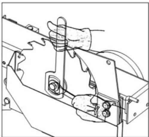
Replacement of saw discs
natural_image
Technical line drawing of a mechanical assembly with hands operating a tool (no text or symbols present)Move the saw unit by means of a hand wheel up to the highest perpendicular position. Push the sliding table to its rear end position, release and take off the protective cover of the saw discs and insert securing spanner into the main shaft so that it cannot turn. Unscrew nut by turning it anticlockwise, remove flange and old saw disc.
Check before mounting the new saw disc whether its seating surfaces are clean and without any bulges. Tighten the saw disc, close and secure the protective cover of saw discs.

WARNING! before replacing the saw blade, check and make sure that the new saw blade is suitable.
The saw blade should have a diameter of 254mm. Its maximum speed should be higher than the saw spindle rotation speed. For safety, the saw blade used should comply with EN 847-1 and suitable for manually feed ('MAN' marked on the saw blade).
Relation of the saw disc thickness, width of teeth and the thickness of the riving wedge
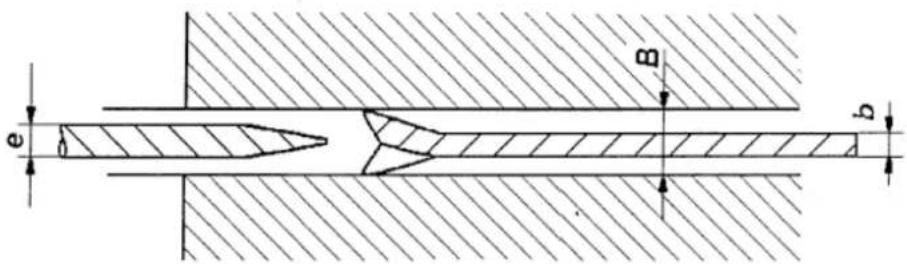
The machine design assumes use of saw discs with diameter 254 mm and the teeth width (kerf) (B) of 3 mm. The riving knife which is mounted on the machine is also designed for this type of discs. The width of riving knife (e) is 2.5 mm. Be sure that the thickness of saw blade disc (b) is at least 0.2mm less than the width of riving knife (e).

WARNING! Use of any other riving knife or discs with any other dimensions may cause injure to
operator or damage to machine.
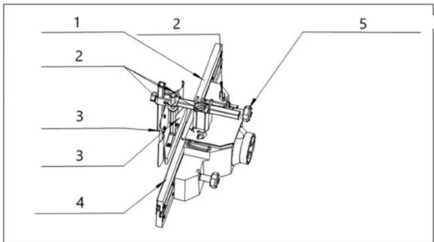
Replacement of moulding tools
Only use moulding tools that are designed for manual feeding and may be clamped firmly and safely. Only tools conforming to EN847-1:2005 and marked MAN shall be used. When changing tools, making adjustments or doing clean-up and maintenance, always turn the machine off and unplug the machine from its power source.
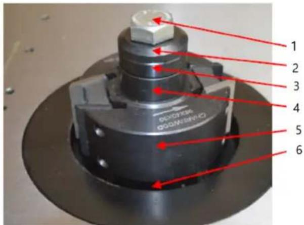
The mouder spindle is manufactured with two segments. The upper tool-clamping section is separated joined to the main mouder spindle with a screw. This two-part construction enables the easy exchange and use of various size spindle diameters on a single machine.
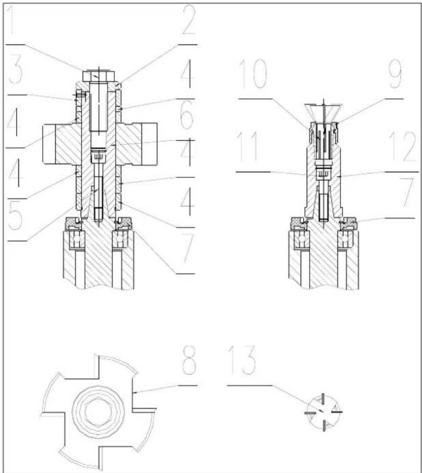
1- Hex bolt
2- Washer
3- Spacing ring with pin
4- Spacing rings
5- Screw
6- Spindle
7- Chip deflector
8- Rebating cutterblock
9- Router collet nut
10- Router collet
11- Screw
12- Router spindle
13- Router bit (12 mm)
Installing and removing the upper spindle from machine
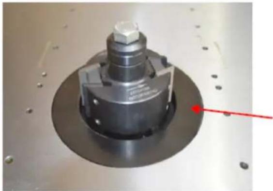
First all, rise the main spindle the higher the better by rotating the hand wheel.
Rotate the tapered spindle slowly whilst pressing the locking bar inwards.
When the lock engages the bar will slide in around 10mm and the spindle will be locked.
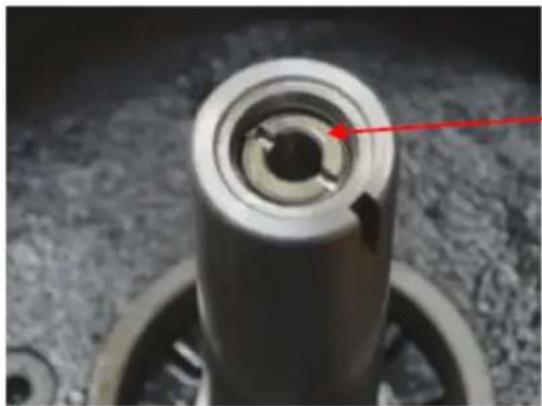
natural_image
Close-up of a mechanical component with a red arrow pointing to a circular hole (no text or symbols visible)With the tapered spindle locked, fit the upper spindle.
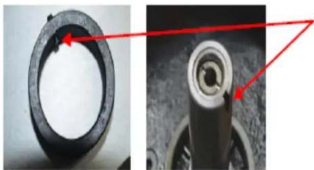
Use a flat screwdriver to unscrew the locking ring in the centre of the upper spindle.
Place the upper spindle over the taper and tighten the retaining screw by passing a 6mm Allen key into the centre of the spindle.
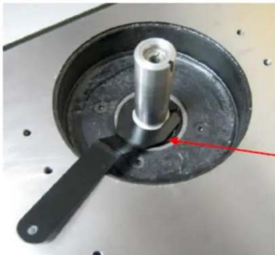
natural_image
Close-up of a mechanical component with a central shaft and circular base, featuring a red arrow pointing to a specific part (no text or symbols visible)Next use the flat screwdriver to tighten the locking ring down onto the head of the retaining screw.

WARNING! Failure to tighten the locking ring may result in the arbor and cutter block coming loose.
If the bolt holding the upper and tapered spindle together ever comes loose, it will be necessary to use the special spanner provided to hold the upper spindle in place whilst unlocking the top bolt.
natural_image
Close-up of a mechanical component with a red arrow pointing to a small feature, no visible text or symbols.Fitting a cutter block.
The cutter block (not included) is shown here assembled.
The larger of the two table inserts is fitted into the table aperture. Always fit the smallest table insert which the tooling allows.
A large selection of spacers, in varying widths are provided so that the cutter block can be located at the right height on the spindle.
natural_image
Close-up of a mechanical component with red arrows pointing to features, no visible text or symbolsWhen stacking the spacers, ensure that the one with the roll pin is at the top of the stack and that the pin engages with the slot in the spindle. (not all of the spacers will be required)
Before fitting the cutter block onto the spindle, engage the spindle lock.
1- The locking bolt
2- The top cap
3- The spacer with the roll pin
4- Some other spacers
5- The cutterblock
6- Some more spacers
The locking bolt must be firmly tightened. Once the stack on the spindle is tight, release the spindle rotation lock, before starting the machine.
The router collet is mounted in the same way.
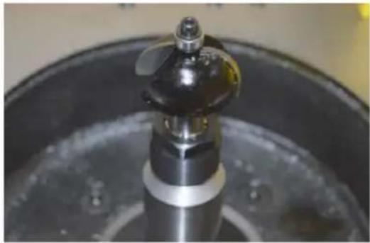
natural_image
Close-up of a metallic mechanical component with a propeller, mounted on a circular base (no visible text or symbols)At last, pull the bar out to unlock the spindle.
When installing the moulding tools, the cover of guard needs to be opened. Loose the two locking knobs to open the cover. After installation, close the cover and lock it through the locking knobs.

WARNING! Always close the cover of guard and lock it securely after tools installed.
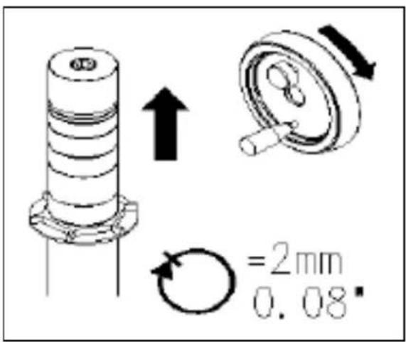
The Spindle Controls
1- Spindle height locking lever
2- Rise and fall hand wheel
One complete turn raises or lowers the arbor by 2mm
3- Spindle rotation lock
Setting cutterhead knives
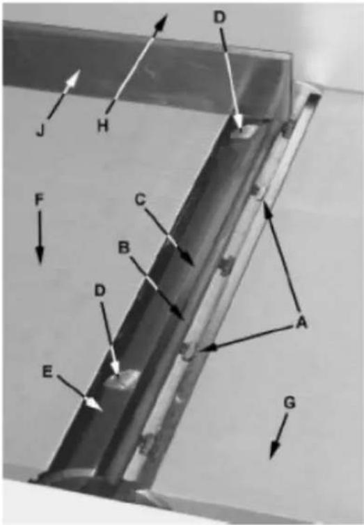
Figure 21

IMPORTANT! Before making any adjustments in this section, the infeed and outfeed tables must be

CAUTION! Cutterhead knives are dangerously sharp! Use extreme caution when inspecting, removing, ting or replacing knives into the cutterhead. Failure to comply may cause serious injury.
- Disconnect machine from the power source.
- Remove the cutterhead guard (B). Referring to Figures 21 and 22.
- Carefully number each knife blade (C) with a magic marker to differentiate each.
Note: To rotate the cutterhead the cutterhead pulley must be turned. This requires removing the panel on the back of the cabinet for access.
- Rotate the cutterhead (E) and determine the 12 o'clock position of knife number one. The 12 o'clock position is the highest point a blade will reach in the cutting arc (C, Fig. 12).
- Set a straightedge (J) on the outfeed table (F) near the fence (H). One end of the straightedge should be positioned over the cutting knife (C) near the end of the blade.
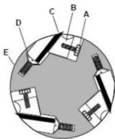
Figure 22
Use care when handling the straightedge near the blades to prevent damage.
Note the position of the knife blade concerning the straight edge, then move the straightedge to the other side of the table and again note the position of the knife blade concerning the straight edge. Blade number one must be at the same height at each end and must also be at the same height as the outfeed table (bottom of straightedge). If this is not the case, adjustment is required as follows:
- Slightly loosen five gib lock screws (A) by turning into the lock bar (B), clockwise as viewed from the infeed table (G).
- Adjust the blade height by turning the jack screws (D) upon which the blades rest. To lower the blade, turn the screw clockwise. To raise, turn the screw counterclockwise.
- When the blade is at the proper height, alternately tighten the five gib lock screws (A).
Repeat steps 4 - 8 for blades two and three.
Replacing cutter knives

CAUTION! Disconnect the machine from power source before making any adjustments. Failure to comply may cause serious injury.
- Disconnect the machine from the power source.
- Remove the cutterhead guard.

CAUTION! Cutterhead knives are dangerously sharp. Use extreme caution when inspecting, removing, sharpening, or replacing knives into the cutterhead. Failure to comply may cause serious injury.
- Turn all five screws (A) into the lock bar (B) by turning in a clockwise direction as viewed from the infeed table (G).
- Carefully remove the cutter knife (C) and lock bar (B).
- Repeat for remaining two knives.
- Thoroughly clean all surfaces of the cutterhead, knife slots and lock bars of any dust or debris.
-
Insert replacement knife (C) into the knife slot, making sure it faces the proper direction.
-
Insert lock bar (B) and tighten just enough to hold in place.
- Repeat for other two blades.
Cleaning and maintenance
- Before starting maintenance or repair work always disconnect the machine from the mains! Turn off the machine and remove the plug from the supply socket!
• Always keep the V-belts (transmission belt for spindle) tight is necessary. - The machine should be cleaned. The rods, pins, threads and other parts liable to be rusty should be lubricated with suitable oil. The interval for such activities will depend on the manner of work but it should be performed at least once a month.
- The bearings of the electrical motors, moulding spindle and circular saw shafts have permanent grease filling, are closed on both sides and do not require any lubrication.
- Avoid contamination of belts with oil or grease. If this occurs, clean the belt with paper only or dry it.
- Removing the dust is best to be done with a vacuum cleaner. Perform this activity regularly, at least once a week.
Transportation and storage
Transportation and storage
While transporting or handling the machine, be most careful and let this activity be done by qualified personnel especially trained for this kind of activity.
While the machine is being loaded or unloaded, make sure that no person or subject gets pressed by the machine!
Do not enter the area under the machine lifted by a crane or a high-lift trolley!
During transporting or storing the machine, means must be taken to protect the machine against excessive vibrations and humidity.
It should be stored in a shelter at temperatures ranging from -25^ to 55^ . As standard, the machine is wrapped up in a plastic tray and is transported this way. Upon request, the machine may also be packed in a robust wooden box.
Lifting of the machine
The machine or its individual parts may only be lifted by means of an approved lifting device with verified lifting capacity.
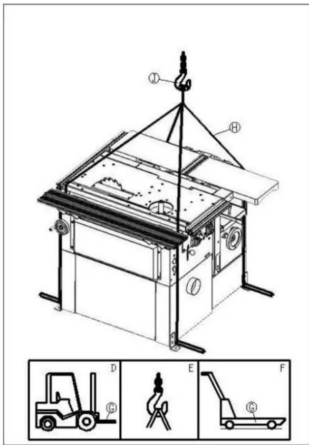
Prepare a high-lift truck (D) or a manual lifting carriage (F) with sufficient lifting capacity, put the forks (G) below the machine, as shown in the picture.
Should you use a crane (E) or a similar hoisting equipment, proceed as follows:
• Prepare four lifting belts (H) or steel ropes at least 2 m long with sufficient lifting capacity.
• Fix the ropes to the hook of the crane with the required capacity.
- Place the other end of the ropes on the lifting rods put under the machine (rods are not part of delivery).
• After lifting the machine slightly, check the stability of the machine hanging on the ropes.
- Lift the machine carefully and slowly and then move it without any rapid changes of the movement to the selected place.
Disposing of used devices
Do not dispose of this device in municipal waste systems. Hand it over to an electric and electrical device recycling and collection point. Check the symbol on the product, instruction manual, and packaging. The plastics used to construct the device can be recycled following their markings. By choosing to recycle you are making a significant contribution to the protection of our environment.
Contact local authorities for information on your local recycling facility.
Troubleshooting
No faults should occur while the machine is used correctly and maintained duly. If any saw dust becomes stuck on the saw disc, or if the exhausting hose is blocked with chips, the machine should be switched off before handling. If a workpiece becomes jammed, turn off the machine immediately!
A blunt saw disc or tool often causes that the electric motor becomes heated excessively. If the machine vibrates excessively, check its setting and anchoring, possibly also clamping and balancing of the tools used.
| Problem | Possible |
| The machine does not work | It will be necessary to check the electrical wiring and connection of the machine to the mains. |
| The thicknessing table moves with difficulties | The table fixing lever should be released or the column should be lubricated. |
| The machine output is low | Tools are not sharp. |
| The chip with too large a thickness is chosen – the width and hardness of the wood should be considered. | |
| The V-belt is not tightened enough. | |
| The motor does not work with the full power output – an expert should be called. | |
| The machine vibrates | Tools not sharpened or adjusted properly. |
| The knives are of different widths. | |
| Unbalanced tools. | |
| The machine is not standing on a flat ground or is fitted improperly. | |
| Thicknessing cannot be performed on the machine | Chips are too thick. |
| The thicknessing table is not clean. | |
| Material is hitting the rear table | The knives or the rear table were incorrectly adjusted. |
| Recess on the rear part of the machined workpiece | Uneven surface during thickening operation. |
| The knives or the tables were incorrectly adjusted. | |
| Incorrectly pressed or guided material during the planing operation. |
caus
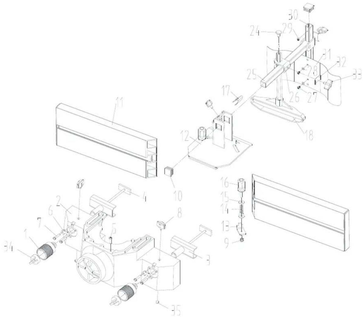
Parts diagram
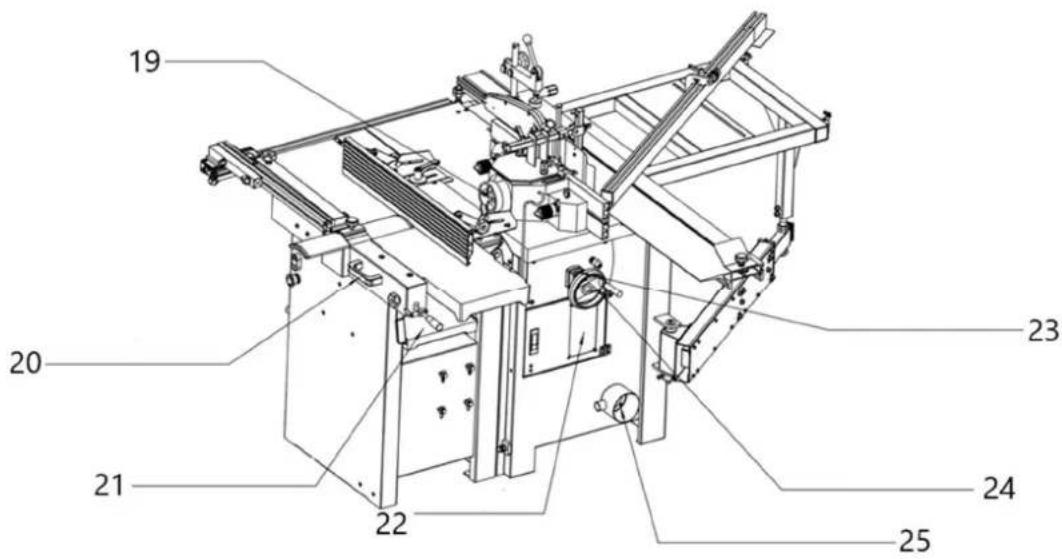
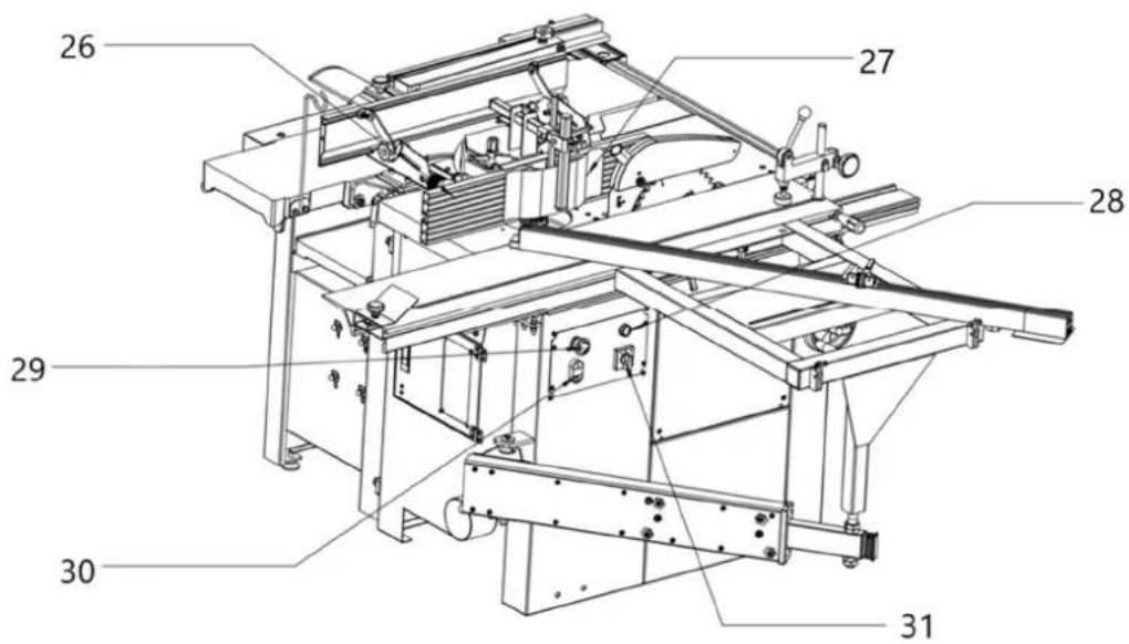
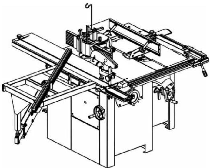
Features
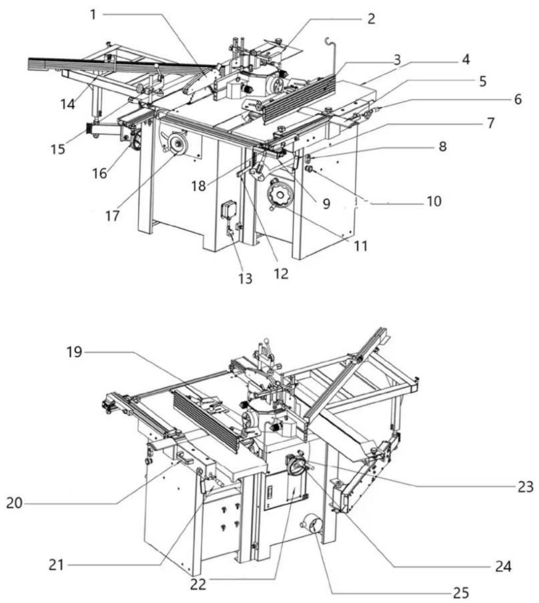

| Part number Description | |
| 1 | Saw Blade Guard |
| 2 | Sliding |
| 3 | Planer Fence |
| 4 | Infeed |
| 5 | Cutterblock |
| 6 | Infeed Table Lifting Handle |
| 7 Planer Table Lock Handle | |
| 8 | ON-OFF Switch |
| 9 | Dust |
| 10 | E Stop Switch |
| 11 Thicknesser Table Height Adjustment | |
| 12 Power Feed ON/OFF Handle | |
| 13 | Plug |
| 14 Ext. Sliding Table | |
| 15 | Work Clamp |
| 16 Saw Tilting Handwheel | |
| 17 | Saw |
| 18 | Saw Fence |
| 19 | Dust |
| 20 | Table Tilt Handle |
| 21 | Thicknesser Table |
| 22 | Looking Door |
| 23 | Position indicator |
| 24 | Mill Height Adjustment |
| 25 | Dust Extraction Outlet |
| 26 | Mill Fence |
| 27 | Pressure Pad |
| 28 | Work Light |
| 29 | E Stop Switch |
| 30 | ON/OFF Switch |
| 31 | Mode Switch |
Tabl
Tabl
Guar
Hoo
hood
Final assembly
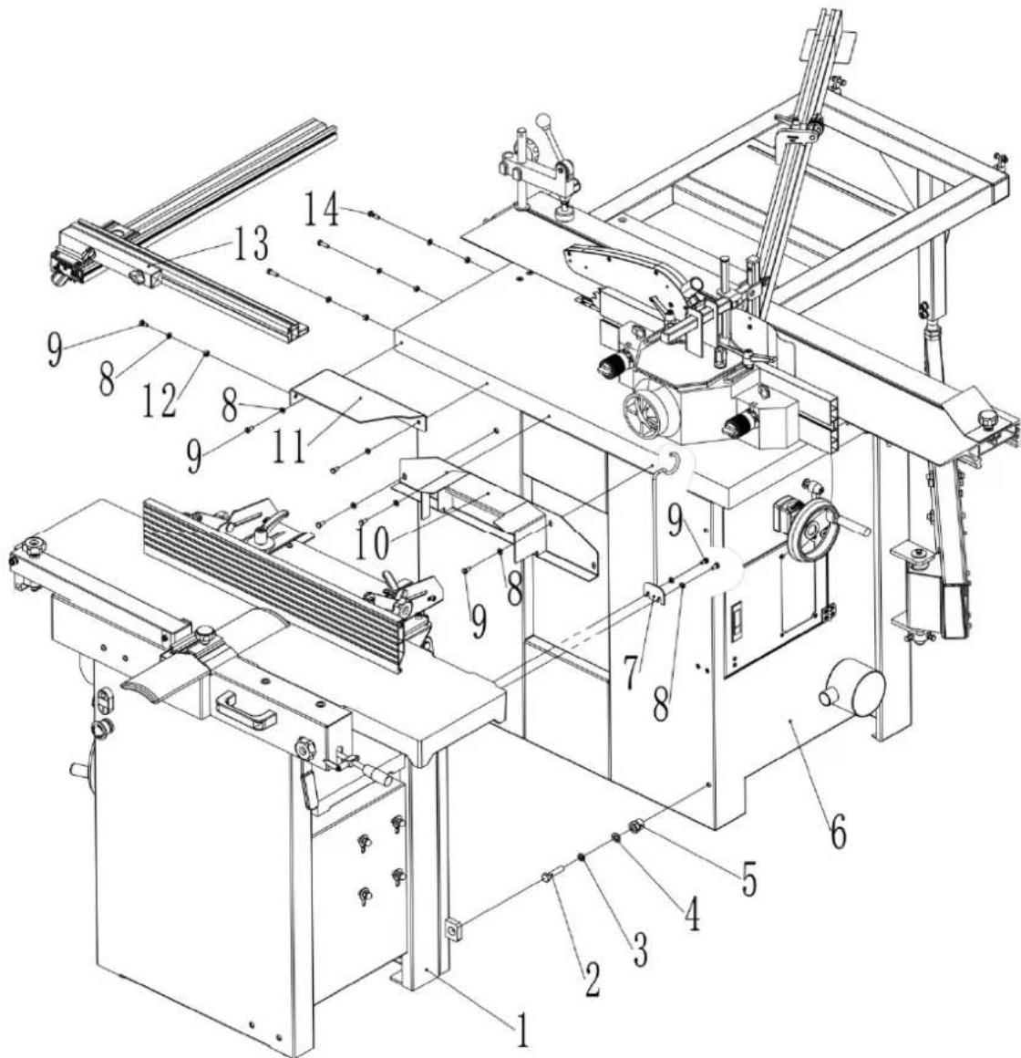
| Part number | Description | Size | Quantity |
| 1 Planer Thicknesser Ass. 1 | |||
| 2 | Hex. | Bolt | M10X45 |
| 3 | Spring | Washer | 10 |
| 4 | Washer | 10 | 4 |
| 5 | Hollow | Bolt | |
| 6 Saw Mill Ass. 1 | |||
| 7 | Support | bracket | |
| 8 | Washer | 6 | 12 |
| 9 | Hex. | Bolt | M6X12 |
| 10 | Link | Cover | |
| 11 | Link table | 1 | |
| 12 | Hex. Nut | M6 | 4 |
| 13 | Saw Fence Ass. | 1 | |
| 14 | Hex. Bolt | M6X20 | 3 |
Saw mill assembly part 1
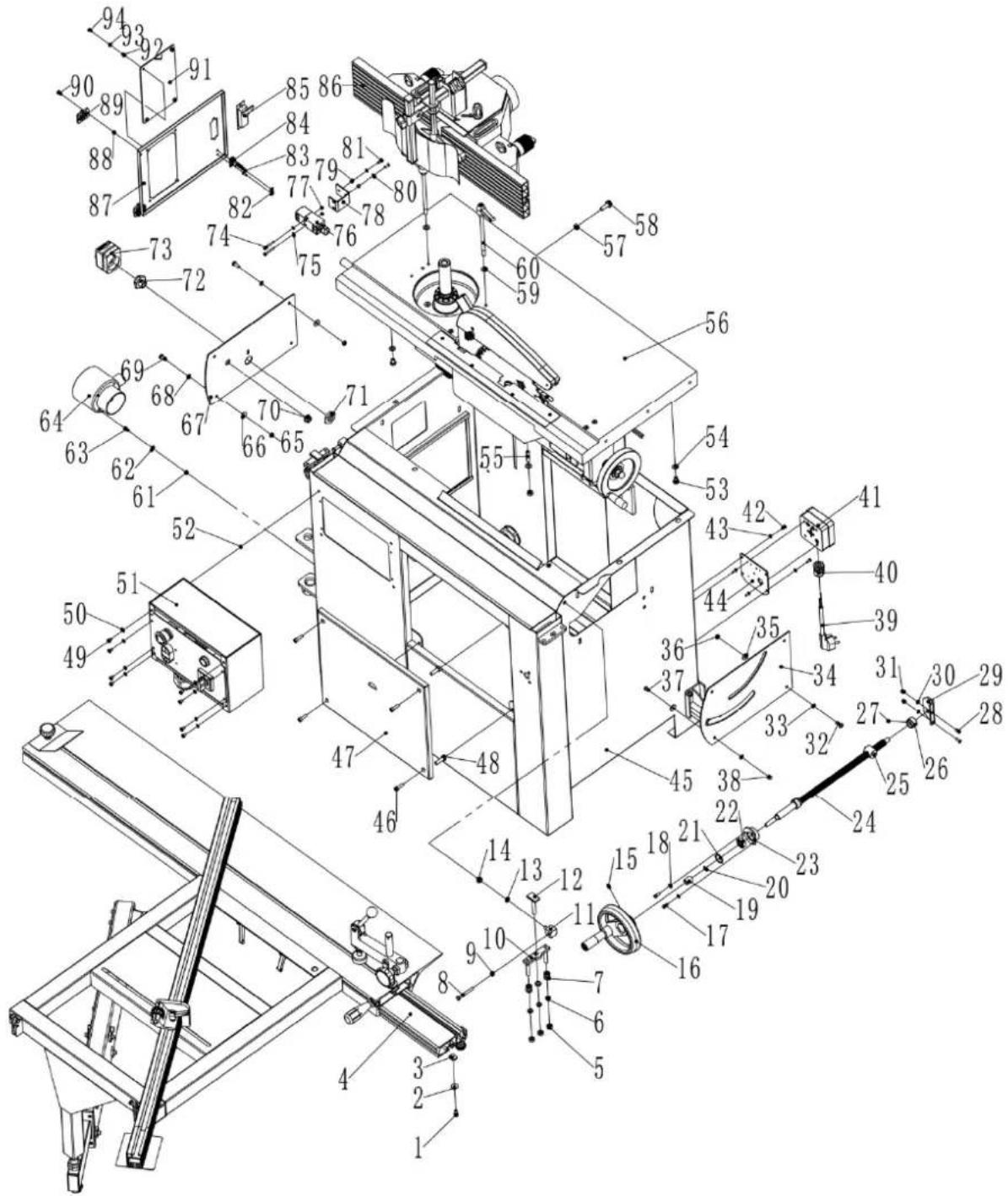
| Part number | Description | Size | Quantif | |
| 1 | Screw | M6X10 | ||
| 2 Very large washer Φ6 | 1 | |||
| 3 | Square | nut | ||
| 4 | Swing table | assembly | ||
| 5 | Hex. | Bolt | ||
| 6 | Spring | Washer | ||
| 7 | Washer | Φ8 | ||
| 8 | Hex. | Bolt | ||
| 9 | Hex. | Nut | ||
| 10 | Adjusting | block | ||
| 11 | Support | block | ||
| 12 | T-bolt | |||
| 13 | Spring | Washer | ||
| 14 | Hex. | Nut | ||
| 15 | Set | Screw | ||
| 16 | Hand wheel | |||
| 17 | Hex. Bolt | M5X12 | ||
| 18 | Washer | Φ5 | ||
| 19 | Space Bush | |||
| 20 | "C" ring | Φ10 | 1 | |
| 21 | "C" ring | Φ26 | 1 | |
| 22 | Bearing | 6000 | 1 | |
| 23 | Bearing Rack | |||
| 24 | Threaded | Shaft | ||
| 25 | Threaded | Nut | ||
| 26 | Limitative | Bush | ||
| 27 | Set | Screw | M8X6 | |
| 28 | Screw | M5X14 | ||
| 29 | Shaft Support | |||
| 30 | Washer | Φ5 | ||
| 31 | Hex. Locking Nut | M5 | ||
| 32 | Pan Screw | M6X16 | ||
| 33 | Washer | Φ6 | ||
| 34 | Saw Panel | |||
| 35 | Large Washer | Φ6 | ||
| 36 | Hex. nut | M6 | ||
| 37 | Screw | M6X12 | ||
| 38 | Pan Nut | M6 | ||
| 39 | Plug | |||
| 40 | Cable Gland | M20 | ||
| 41 | Plug Box | |||
| 42 | Pan Screw | M4X10 | ||
| 43 | Washer | Φ4 | ||
| 44 | Plug | Plate | ||
| 45 | Saw Mill Box | 1 | ||
| 46 | Screw | M6X20 | ||
| 47 | Front Cover | |||
| 48 | Plastic Bolt | |||
| 49 | Screw | M5X8 | 8 | |
| 50 | Washer | Φ5 | ||
| 51 | Switch Box | |||
| 52 | Hex. Bolt | M5 | ||
| 53 | Hex. Bolt | M8X12 | ||
| 54 | Washer | Φ8 | ||
| 55 | Set | Screw | ||
| 56 | Table Ass. | |||
| 57 | Hex. | Nut | ||
| 58 | Hex. Flange Bolt | M8X25 | 2 | |
| 59 | Large Washer | Φ8 | ||
| 60 | Locking shaft | |||
| 61 | Hex. | Nut | ||
| 62 | Washer | Φ5 | ||
| 63 | Pan | Screw | ||
| 64 | Three-way | Pipe | ||
| 65 | Hex. | Nut | ||
| 66 | Large | Washer | ||
| 67 Mill Face Plate 1 | ||||
| 68 | Washer | 6 | ||
| 69 | Pan | Screw | ||
| 70 | Bush | |||
| 71 | Hex. | Nut | ||
| 72 | Hex.Bush | |||
| 73 | Position indicator | |||
| 74 | Pan | Screw | ||
| 75 | Washer | 4 | ||
| 76 | Micro-switch | QKS8 | 1 | |
| 77 | Hex. | Nut | ||
| 78 | Switch Plate | |||
| 79 | Hex. | Nut | ||
| 80 | Washer | 5 | ||
| 81 | Screw | MX16 | ||
| 82 | Key Fixing | Plate | ||
| 83 | Pan | Screw | ||
| 84 | Key | |||
| 85 | Door lock | 703-2 | 1 | |
| 86 | Exhaustion Socket Ass. | |||
| 87 | Door | |||
| 88 | Hex. Locking nut | M5 | ||
| 89 | Hinge | 30X40 | 2 | |
| 90 | Screw | MX12 | ||
| 91 | Look window | |||
| 92 | Hex. | Nut | ||
| 93 | Washer | 5 | ||
| 94 | Screw | M$X10 | ||
Saw mill assembly part 2
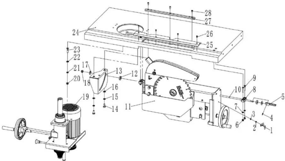
| Part number | Description | Size | Q |
| 1 | Pointer | ||
| 2 | Pan | Screw | M4x6 |
| 3 | Tooth | Washer | |
| 4 | Pin | 3X12 | |
| 5 | Locking | Handle | |
| 6 | Hex. Locking | Nut | |
| 7 | Washer | 6 | |
| 8 | Support | block | |
| 9 | Screw | M6X35 | 4 |
| 10 | Locking Shaft | 1 | |
| 11 | Saw ASS. | 1 | |
| 12 | Thick Washer | 2 | |
| 13 | Inner Locking Plate | 1 | |
| 14 | Hex. bolt | M8X16 | 2 |
| 15 | Spring Washer | 8 | 2 |
| 16 | Washer | 8 | 2 |
| 17 | Large Washer | 8 | 2 |
| 18 | Hex. Locking Nut | M8 | 1 |
| 19 | Mill Ass. | 1 | |
| 20 | Hex. nut | M8 | 4 |
| 21 | Spring Washer | 8 | 4 |
| 22 | Washer | 8 | 4 |
| 23 | Screw | M8X30 | 4 |
| 24 | Table | 1 | |
| 25 | Guard Plate | 1 | |
| 26 | Screw | M4X10 | 4 |
| 27 | Insert | 1 | |
| 28 | Screw | M5X10 | 3 |
1
Saw mill assembly
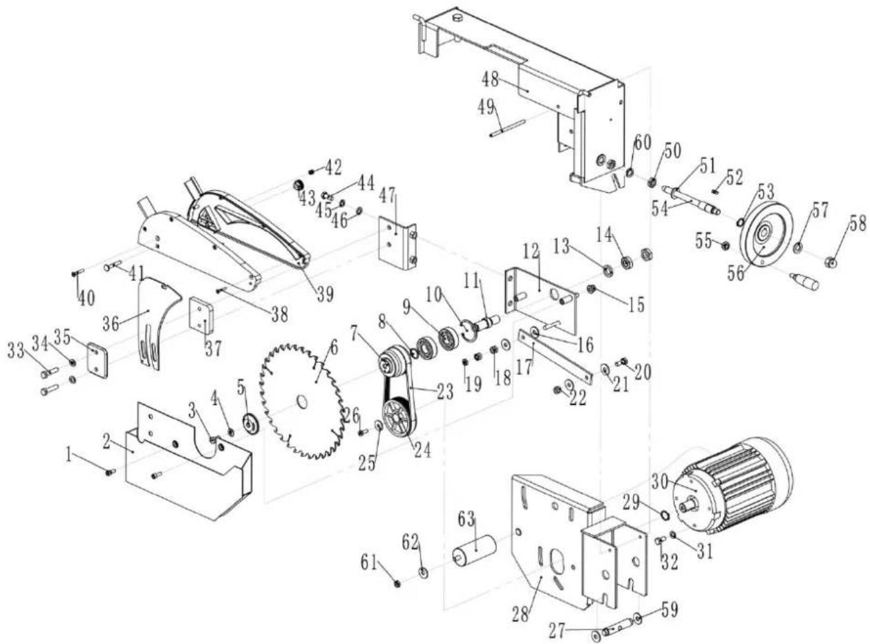
| Part number | Description | Size | Quantity |
| 1 | Screw | M6X16 | |
| 2 | Dust | Collector | |
| 3 | Hex. | Bolt | M8X16 |
| 4 | Washer | 8 | |
| 5 | Platen | ||
| 6 | Saw | blade | |
| 7 | Driven | Pulley | |
| 8 | "C" | Ring | 20 |
| 9 | Bearing | 6204 | 2 |
| 10 | "C" Ring | 47 | |
| 11 | Saw AXIS | 1 | |
| 12 | Parallel Plate | 1 | |
| 13 | Spring Washer | 16 | |
| 14 | Thin Nut | M16 | 2 |
| 15 | Hex. Locking nut | M8 | 2 |
| 16 | Large Washer | 8 | 2 |
| 17 | Connecting plate | 1 | |
| 18 | Hex. Locking nut | M8 | 2 |
| 19 | Hex. Thin Nut | M8 | 1 |
| 20 | Hex. Bolt | M8X20 | 1 |
| 21 | Large Washer | 8 | 2 |
| 22 | Hex. Locking Nut | M8 | 1 |
| 23 | Cuneal Belt | 5J482 | 1 |
| 24 | Motor | Pulley | |
| 25 | Very Large | Washer | |
| 26 | Hex. | Bolt | M6X16 |
| 27 | Rotation | Shaft | |
| 28 | Motor | Rack | |
| 29 | "C"Ring | Φ19 | |
| 30 | Motor | ||
| 31 | Washer | Φ8 | |
| 32 | Hex. | bolt | M8X16 |
| 33 | Hex. | Bolt | M8X35 |
| 34 | Washer | Φ8 | |
| 35 | Clamp | Plate | |
| 36 | Riveting Wedge | ||
| 37 | Clamp | Plate | |
| 38 | Screw | M3.5X25 | 4 |
| 39 | Dust Collector | 1 | |
| 40 | Screw | M5X30 | 1 |
| 41 | Bolt | M6X40 | 1 |
| 42 | Hex. Locking Nut | M5 | 1 |
| 43 | Locking Nut | 1 | |
| 44 | Hex. Bolt | M8X20 | 2 |
| 45 | Spring Washer | Φ8 | 2 |
| 46 | Washer | Φ8 | 2 |
| 47 | Parallel Plate | 1 | |
| 48 | Turning Support | 1 | |
| 49 | Pin | 8X110 | 1 |
| 50 | Thin Hex. Nut | M12 | 2 |
| 51 | Washer | Φ12 | 1 |
| 52 | Key | 5X15 | 1 |
| 53 | "C" Ring | Φ16 | 1 |
| 54 | Bolt Shaft | 1 | |
| 55 | Hex. Nut | M8 | 1 |
| 56 | Hand Wheel | 1 | |
| 57 | Washer | Φ12 | 1 |
| 58 | Hex. Nut | M12 | 1 |
| 59 | Washer | Φ16 | 2 |
| 60 | Spring Washer | Φ12 | 2 |
| 61 | Hex. Nut | M8 | 1 |
| 62 | Large Washer | Φ8 | 1 |
| 63 | Capacitor | 1 | |
Outrigger table assembly
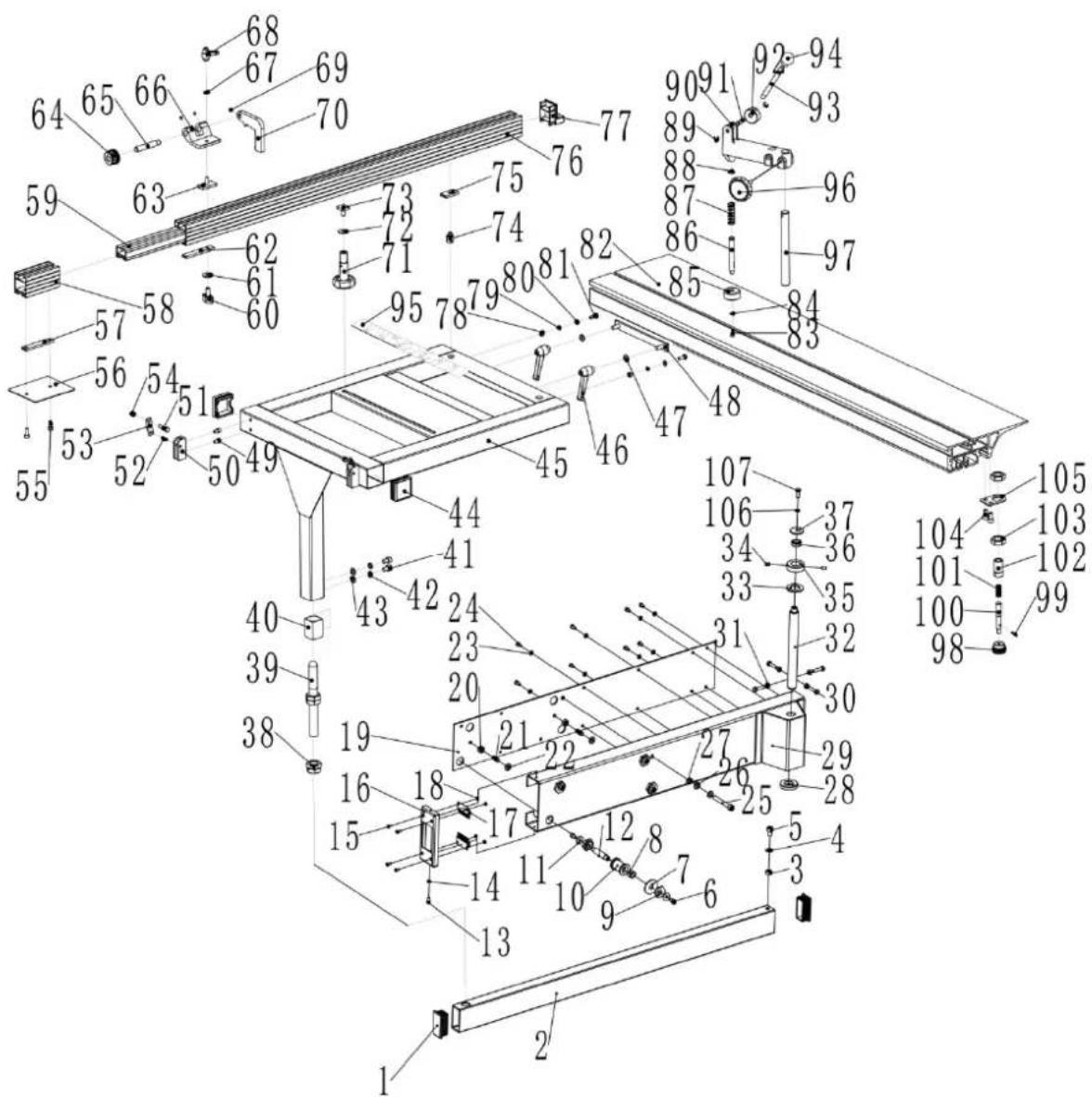
| Part number | Description Size Quantity | ||
| 1 | Tube | cap | 30X6 |
| 2 | Telescopic | tube | |
| 3 | Hex | Nut | M8 |
| 4 | Washer | 8 | |
| 5 | Screw | M8X12 | |
| 6 | Screw | M6X10 | |
| 7 | Special | Washer | |
| 8 | Bearing | 1241D | 8 |
| 9 | Eccentric Nut | ||
| 10 | wheel | 4 | |
| 11 | Large Washer | 6 | 8 |
| 12 | Shaft | 4 | |
| 13 | Screw | M6X8 | 2 |
| 14 | Washer | 5 | 2 |
| 15 | Screw | M4X10 | 4 |
| 16 | End Cover | 1 | |
| 17 | Brush | ||
| 18 | Hex | Nut | |
| 19 | Tube | Cover | |
| 20 | Hex. | Nut | |
| 21 | Plastic | Bolt | |
| 22 | Washer | Φ8 | |
| 23 | Washer | Φ5 | |
| 24 | Screw | M5X8 | |
| 25 | Screw | M8X60 | |
| 26 | Washer | Φ8 | |
| 27 | Hex. | Nut | |
| 28 | Press Washer | ||
| 29 | Support For Telescopic Tube | 1 | |
| 30 | Hex. Bolt | M6X25 | 4 |
| 31 | Hex. | Nut | |
| 32 | Shaft | ||
| 33 | Washer | Φ20 | 1 |
| 34 | Set Screw | M6X8 | 2 |
| 35 | Press Ring | ||
| 36 | Bearing | GE12E | 1 |
| 37 | Large Washer | ||
| 38 | Hex thin nut | M20X1.5 | 4 |
| 39 | Support rod | ||
| 40 | Link block | ||
| 41 | Screw | M8X12 | |
| 42 | Spring washer | Φ8 | |
| 43 | Washer | Φ8 | |
| 44 | Tube cap | ||
| 45 | Ext. sliding table | 1 | |
| 46 | Handle | ||
| 47 | Washer | Φ8 | |
| 48 | Clamping plate | ||
| 49 | Screw | M6X8 | 4 |
| 50 | Positive block | ||
| 51 | Hex bolt | M6X25 | 2 |
| 52 | Spring pin | 6X16 | 2 |
| 53 | Limited plate | ||
| 54 | Hex locking nut | M6 | |
| 55 | Screw | M6X16 | |
| 56 | Location plate | ||
| 57 | Fixing | plate | |
| 58 | Ext. bracket for lengthened | 1 | |
| 59 | Main bracket for lengthened ruler | 1 | |
| 60 | Knob | ||
| 61 | Large washer | Φ8 | |
| 62 | Fixing | plate | |
| 63 | T-bolt | ||
| 64 | Adjusting button | ||
| 65 | Bolt | ||
| 66 | Bracket | ||
| 67 | Washer | Φ6 | |
| 68 | Small handle | ||
| 69 | Set screw | M5X5 | 3 |
| 70 | Location block | ||
| 71 | Long handle |
12 1
2
2
| 72 | Large | washer | |
| 73 | Square | bolt | |
| 74 | Pivot | ||
| 75 | Square | nut | |
| 76 | Fence | 1200 | |
| 77 | Fence | cover | |
| 78 | Hex | nut | |
| 79 | Spring washer | Φ6 | |
| 80 | Washer | Φ6 | |
| 81 | Hex bolt | M6X16 | 2 |
| 82 | Sliding table Ass. | 1 | |
| 83 | Screw | M5X10 | 1 |
| 84 | Washer | Φ5 | |
| 85 | Press rod | ||
| 86 | Press pole | ||
| 87 | Spring | ||
| 88 | "C"ring | Φ12 | 1 |
| 89 | "E"ring | Φ6 | |
| 90 | Press | bracket | |
| 91 | Pin | ||
| 92 | Press | wheel | |
| 93 | Hand pole | ||
| 94 | Handball | ||
| 95 | Angle | ruler | |
| 96 | Locking knob | ||
| 97 | Spindle | ||
| 98 | Knob | ||
| 99 | Spring pin | Φ3X16 | 1 |
| 100 | Sliding pole | 1 | |
| 101 | Spring | 1 | |
| 102 | Rest bush | 1 | |
| 103 | Thin nut | M16X1.5 | 2 |
| 104 | Screw | M6X12 | 2 |
| 105 | Link | plate | |
| 106 | Spring Washer | Φ6 | 1 |
| 107 | Hex. Bolt | M6X16 | 1 |
mm
Fence assembly
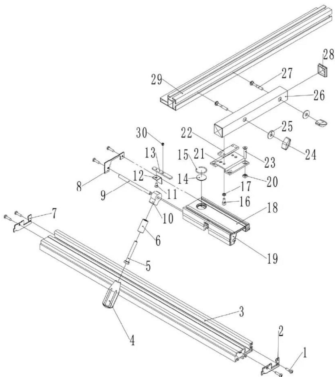
| Part number | Description | Size | Quantity |
| 1 | Screw | ST4.2X9.5 | |
| 2 | Base | Cover | R |
| 3 | Base | ||
| 4 | Hollow | Handle | |
| 5 | Hex. | Bolt | M8X60 |
| 6 | Space | Bush | |
| 7 Base Cover L | 1 | ||
| 8 | Cover L | ||
| 9 | Pin | ||
| 10 | Locking | block | |
| 11 | Screw | M4X8 | 1 |
| 12 | Tongue plate | 1 | |
| 13 | Link Plate | 1 | |
| 14 | Reading | Glass | |
| 15 | Steel | Ring | |
| 16 | Screw | M6X12 | |
| 17 | Spring | Washer | |
| 18 | Sliding | Bracket | |
| 19 | Cover | R | |
| 20 | Square | nut | |
| 21 | Bridge Plate | ||
| 22 | Screw | Bar | |
| 23 | Screw | M6X10 | |
| 24 | Handgrip | ||
| 25 | Large | Washer | |
| 26 | Square Tube | ||
| 27 | Square Neck Bolt | M8X40 | 2 |
| 28 | Tube Cap | ||
| 29 | Fence | ||
| 30 | Set Screw | M6X6 | 1 |
4
4
1
1
Mill assembly
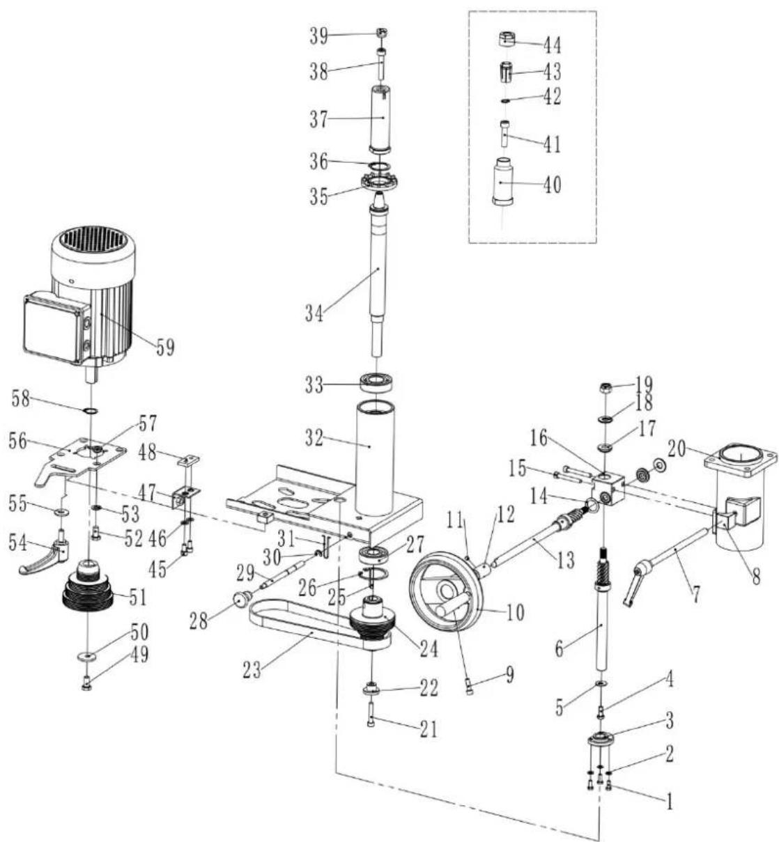
| Part number | Description | Size | Quantity |
| 1 | Hex | bolt | M5X12 |
| 2 | Washer | 5 | |
| 3 | Nut | bush | |
| 4 | Hex | bolt | M6X16 |
| 5 | Large | washer | |
| 6 | Gear | shaft | |
| 7 | Locking | pole | |
| 8 | Locking | block | |
| 9 | Screw | M6X20 | |
| 10 | Handwheel | ||
| 11 | Set Screw | M6X6 | 1 |
| 12 | Linking pole | ||
| 13 | Gear shaft | ||
| 14 | Thin | washer | |
| 15 | Screw | M6X45 | |
| 16 | Gear | Box | |
| 17 | Gear | bush | |
| 18 | Bearing | AXK1024 | |
| 19 | Hex locking | nut | |
| 20 | Oriented | stand | |
| 21 | Screw | M6X35 | |
| 22 | Circular | washer | |
| 23 | Cuneal | belt | 5PJ508 |
| 24 | Driven pulley | ||
| 25 | Key | 5X35 | 1 |
| 26 | "C" ring | Φ47 | 1 |
| 27 | Bearing | 6204 | 1 |
| 28 | Handgrip | ||
| 29 | Locking pole | ||
| 30 | "E" ring | Φ6 | 1 |
| 31 | Spring | clip | |
| 32 | Motor rack | ||
| 33 | Bearing | 6205 | 1 |
| 34 | Spindle | ||
| 35 | Fan cap | ||
| 36 | "C" ring | Φ30 | 1 |
| 37 | Interchangeable Spindle | ||
| 38 | Screw | M8X45 | |
| 39 | Prevent Nut | ||
| 40 | Interchangeable Spindle | ||
| 41 | Screw | M8X35 | |
| 42 | "C" ring | Φ13 | 1 |
| 43 | Router Collet | ||
| 444 | Router Collet Nut | 1 | |
| 45 | Screw | M6X14 | |
| 46 | Washer | Φ6 | 2 |
| 47 | Angle | plate | |
| 48 | Plate | ||
| 49 | Hex bolt | M6X16-L | 1 |
| 50 | Large Washer | ||
| 51 | Motor pulley | ||
| 52 | Hex bolt | M8X16 | 4 |
| 53 | Washer | Φ8 | 4 |
| 54 | Locking handle | ||
| 55 | Large washer | Φ8 | 1 |
| 56 | Rotation plate | ||
| 57 | Space Bush | ||
| 58 | "C" ring | Φ19 | 1 |
| 59 | Motor | ||
Mill exhaustion socket assembly
| Part number | Description | Size | Quantity |
| 1 | Adjusting | wheel | |
| 2 | Exhaustion | socket | |
| 3 | Guide | rack | |
| 4 | T-shaped | bolt | |
| 5 | Screw | M6X10 | |
| 6 | Metal | plate | |
| 7 | Hex | bolt | M5X12 |
| 8 | Rhombic handgrip | ||
| 9 | Hex locking nut | M6 | 2 |
| 10 | Square plastic end | 3 | |
| 11 | T-shaped rail | 2 | |
| 12 | Turing rack | 1 | |
| 13 | Locking sheet metal | 2 | |
| 14 | Spring | 2 | |
| 15 | Large washer | 6 | 2 |
| 16 | Handgrip | 2 | |
| 17 | Saucer | 2 | |
| 18 | Hexangular leader | 1 | |
| 24 | Bolt | M8X12 | 1 |
| 25 | Square leader | assembly |
| 26 | Capstan | |
| 27 | Screw | M4X6 |
| 28 | Washer | |
| 29 | Screw | M4X6 |
| 30 | Standpipe | |
| 31 Spring protective broad 1 | ||
| 32 | Locking | patch |
| 33 | Rhombic | handgrip |
| 34 | Locking | knob |
| 35 | Set screw | M8X10 |
2
1
Control box assembly
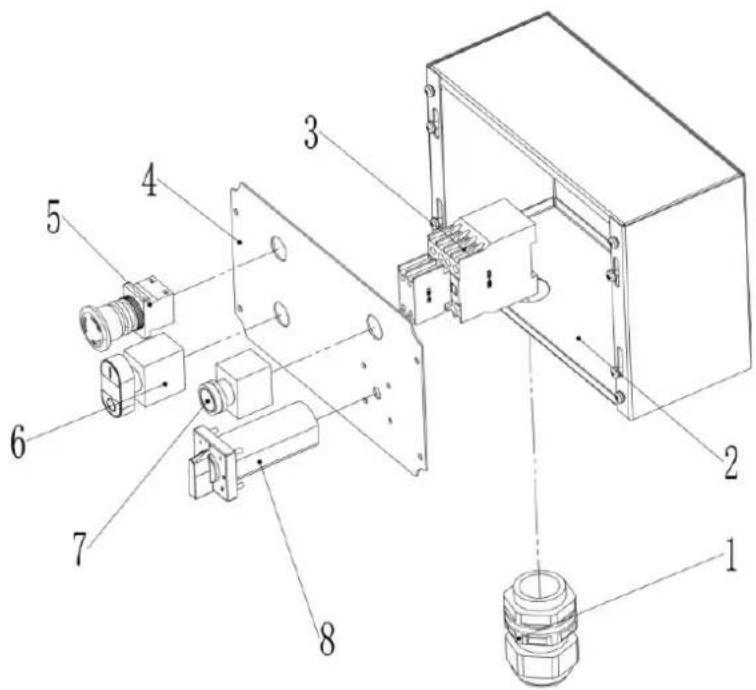
| Part number | Description | Size | Quantity |
| 1 | Cable Gland | M26 | 1 |
| 2 | E Box | 1 | |
| 3 | Contactor | CJX2-1810 | 1 |
| 4 | Control Plate | 1 | |
| 5 | E-stop Switch | 1 | |
| 6 | On-OFF Switch | 1 | |
| 7 | Work Light | 1 | |
| 8 | Mode Switch | 1 |
Planer thicknesser - cutter block guard and outfeed assembly
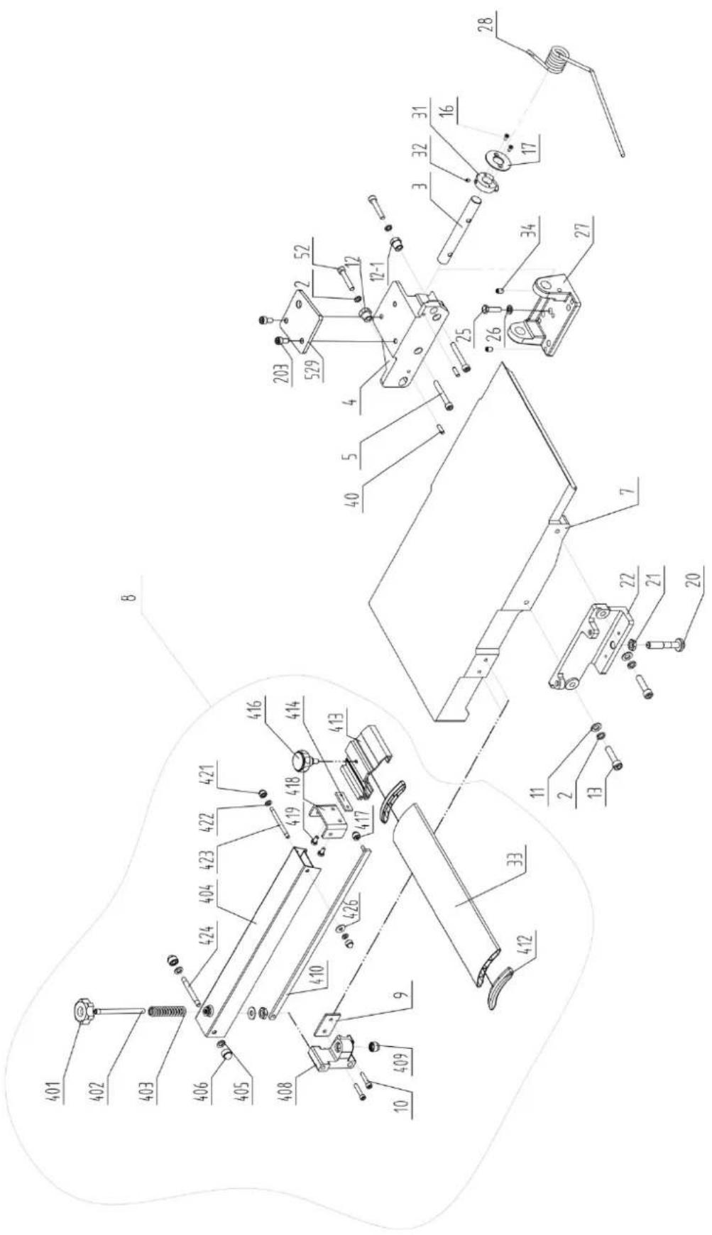
| Part number | Description | Size | Q |
| 2 | Spring | washer | 10 |
| 3 Outfeed | Table Bracket Shaft 1 | ||
| 4 Outfeed | Table Bracket Right 1 | ||
| 5 Hex. Socket Cap Screw M8X60 2 | |||
| 7 | Outfeed | Table | |
| 8 Cutterblock Guard Assembly 1 | |||
| 9 | Plate | ||
| 10 Hex. Socket Cap Screw M6X30 2 | |||
| 11 | washer | 10 | 2 |
| 12 | Hex. bush | 1 | |
| 12-1 | Hex. bush | 1 | |
| 13 Hex. Socket Cap Screw M10X40 | 2 | ||
| 16 | Screw | M4X10 | 2 |
| 17 | Large washer | 1 | |
| 20 | Table Locking Shaft | 1 | |
| 21 | Hex. Nut | M12 | 1 |
| 22 Outfeed | Table Bracket Left 1 | ||
| 25 | Hex. bolt | M8X30 | 3 |
| 26 | Washer | 8 | 5 |
| 27 | Outfeed Table Support | 1 | |
| 28 | Spring | 1 | |
| 31 | Big Cam Wheel for Safety Switch | 1 | |
| 32 | Hex. Socket Set Screw | M6X6 | 1 |
| 33 | Cutterblock Guard Profile W/Cap | 1 | |
| 34 | Hex. Socket Set Screw | M8X12 5 | |
| 40 | Pin | 6X20 | 4 |
| 52 | Hex. Socket Screw | M8X45 | 2 |
| 203 | Hex. Socket Screw | M8X16 | 2 |
| 401 | Lock Knob | 1 | |
| 402 | Lead Screw | 1 | |
| 403 | Spring | 1 | |
| 404 | Bracket for Guard | 1 | |
| 405 | Washer | 8 | 3 |
| 406 | Lock Nut | M8 | 2 |
| 408 | Locking Support | 1 | |
| 409 | Hex. Lock Nut | M8 | 1 |
| 410 | Long Shaft | 1 | |
| 412 | Fixed Press Paw | 2 | |
| 413 | Guard Plate Cover | 1 | |
| 414 | Lock Plate | 1 | |
| 416 | Nylon knob | 1 | |
| 417 | Lock Nut | M6 | 1 |
| 418 | Bracket | 1 | |
| 419 | Hex. bolt | M6X10 | 2 |
| 421 | Lock Nut | M6 | 2 |
| 422 | Nylon Washer | 6 | 2 |
| 423 | Shaft (M6) | 1 | |
| 424 | Shaft (M8) | 1 | |
| 426 | Washer | 6 | 2 |
| 529 | Plate | 1 | |
Quantity
Planer thicknesser - cutter block assembly
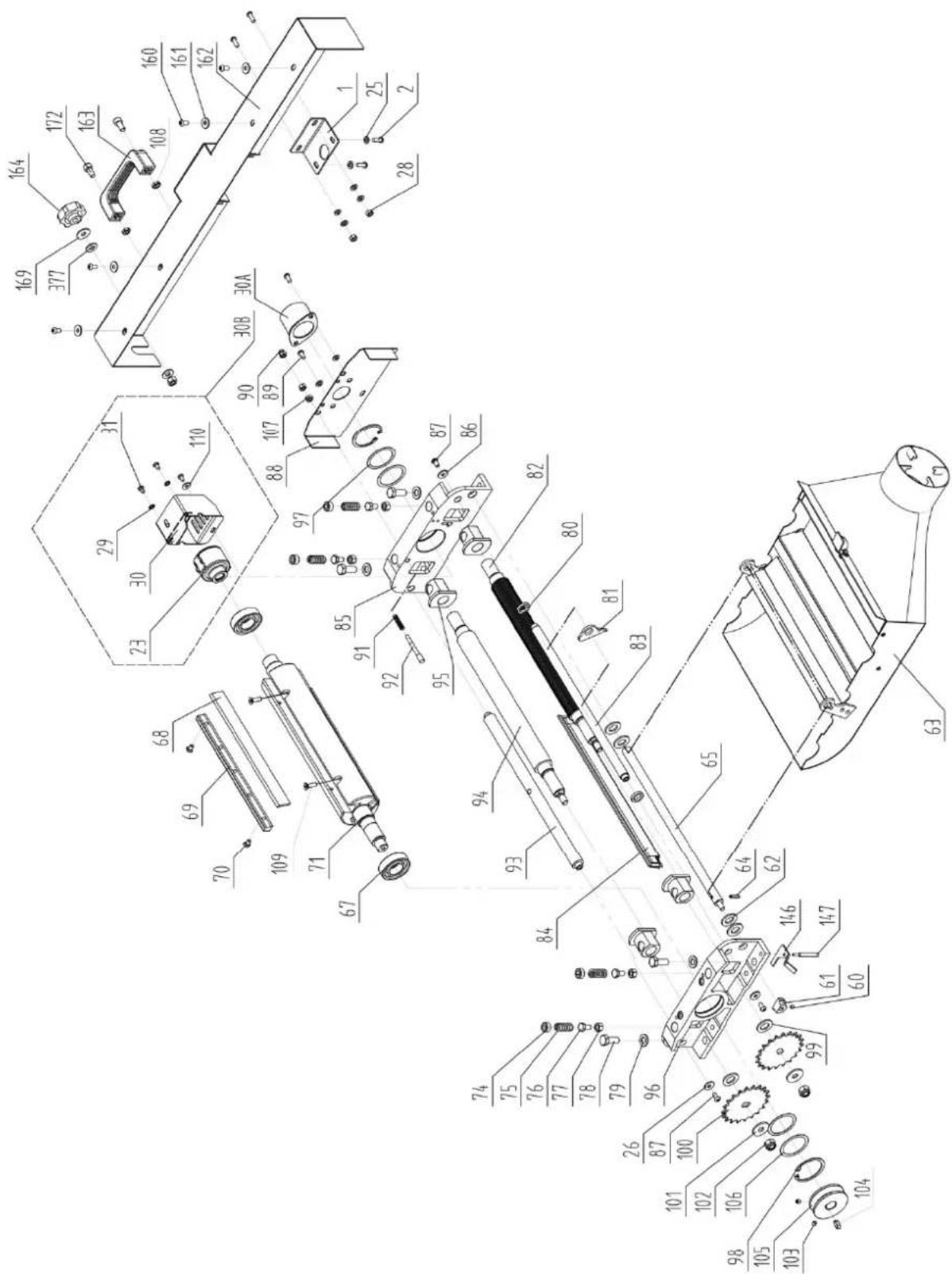
| Part number | Description | Size | Quantity |
| 1 Cover link | plate 1 | ||
| 2 Pan Head Screw M6X16 4 | |||
| 23 | Mortising | head | |
| 25 | Washer | Φ6 | |
| 26 | Large | Washer | |
| 28 | Hex. | nut | |
| 29 | Retained | washer | |
| 30 Cover of mortising head 1 | |||
| 31 Pan head screw M5X8 | 3 | ||
| 30A | Cover of cutterblock head | 1 | |
| 60 | Hex. Socket Set Screw | M6X6 | 1 |
| 61 | Small cam wheel | 1 | |
| 62 | Washer | Φ14 | 4 |
| 63 | Dust Collector Assembly | ||
| 64 | Pin Roll | 5X18 | 1 |
| 65 | Shaft | ||
| 67 | Bearing | 6205-2Z | 2 |
| 68 | Knife | ||
| 69 | Knife Locking Bar | 3 | |
| 70 | Special Screw for Locking Bar | 15 | |
| 71 | Cutter Block | ||
| 74 | Screw | ||
| 75 | Spring | ||
| 76 | Hex. Bolt | M8X14 | 4 |
| 77 | Hex. Thin Nut | M8 | 4 |
| 78 | Hex. Bolt | M10X25 | 4 |
| 79 | Washer | Φ10 | 4 |
| 80 | Space Washer | ||
| 81 | Anti-Kickback Finger | ||
| 82 | Infeed Roller | ||
| 83 | Anti-Kickback Shaft | ||
| 84 | Cutterblock Cover | ||
| 85 | Cutterblock Bracket-Left | ||
| 86 | Large | Washer | |
| 87 | Hex. Socket Cap Screw M6X12 2 | ||
| 88 | Cutterblock Bracket Cover | ||
| 89 | Pan Head Screw M6X12 2 | ||
| 90 | Cap Nut | M6 | 1 |
| 91 | Spring | ||
| 92 | Pin Stop for Dust Collector | 1 | |
| 93 | Support Rod | ||
| 94 | Outfeed Roller (Rubber) | ||
| 95 | Tube (Powder Metal Bushing) 4 | ||
| 96 | Cutterblock Bracket-Right | ||
| 97 | Wave Washer | D52 | 2 |
| 98 | Retaining Ring | CLP52 | 2 |
| 99 | Washer (black) | Φ14 | 2 |
| 100 | Drive Chain Sprocket | 2 | |
| 101 | Large Washer | Φ10 | |
| 102 | Lock Nut | M10 | |
| 103 | Hex. Socket Set Screw | M6X6 | 2 |
| 104 | Key | 6X16 | 2 |
1
1
43
33
1
1
1
1
1
1
1
1
2
(
| 105 | Spindle | Pulley | |
| 106 | Washer | D52 | |
| 107 | Hex. | Nut | |
| 108 Hex. Thin Nut M8 2 | |||
| 109 Hex. Socket Pan Screw M6X20 6 | |||
| 110 | Large | Washer | |
| 146 | Safety Switch Rocker | ||
| 147 | Safety Switch Rocker Shaft | M6X12 | 1 |
| 160 | Pan Head Screw | M6X12 4 | |
| 161 | Large washer | 6 | |
| 162 | Front Cover | ||
| 163 | Handle | 1 | |
| 164 | Lock knob | ||
| 169 | Large | Washer | |
| 172 | Hex. Socket screw | M8X16 2 | |
| 377 | Nylon Washer | 8 | |
Planer thicknesser - base assembly
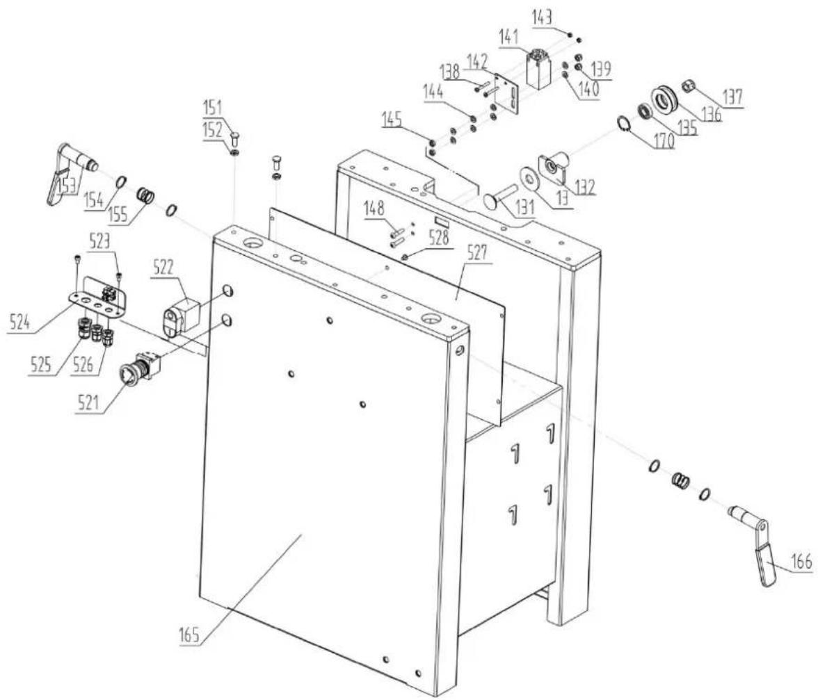
| Part number | Description | Size | Quantity |
| 13 | Large Washer | 1 | |
| 131 | Carriage Bolt | M12X65 | 1 |
| 132 | Tube |
1
4
1
1
2
| 135 | Bearing | 6001-2Z | |
| 136 | Chain Tension | Wheel | |
| 137 | Lock | Nut | |
| 138 Pan Head Screw M4X30 2 | |||
| 139 | Lock | Nut | |
| 140 | Washer | 6 | |
| 141 | Safety | Switch | |
| 142 | Safety Switch Bracket | ||
| 143 | Hex. | Nut | |
| 144 | Washer | 6 | |
| 145 | Hex. | Nut | |
| 148 | Hex. Socket Cap Screw | M6X25 2 | |
| 151 | Special Bolt | ||
| 152 | Hex. Thin Nut | M8 | 4 |
| 153 | Lock Handle For Outfeed Table | 1 | |
| 154 | Retaining Ring | CLP20 | 4 |
| 155 | Spring | 2 | |
| 165 | Cabinet | 1 | |
| 166 | Lock Handle For Infeed Table | 1 | |
| 170 | Retaining Ring | CLP28 | 1 |
| 521 | E-stop | Switch | |
| 522 | ON-OFF Switch | 1 | |
| 523 | Hex. Socket Screw | M5X8 | 2 |
| 524 | E-Plate | ||
| 525 | Cable Gland | M16 | |
| 526 | Cable Gland | M12 | |
| 527 | Inner Cover | ||
| 528 | Hex. Socket Screw | M5X8 | 5 |
1
1
4
1
1
2
1
Planer thicknesser – infeed table assembly
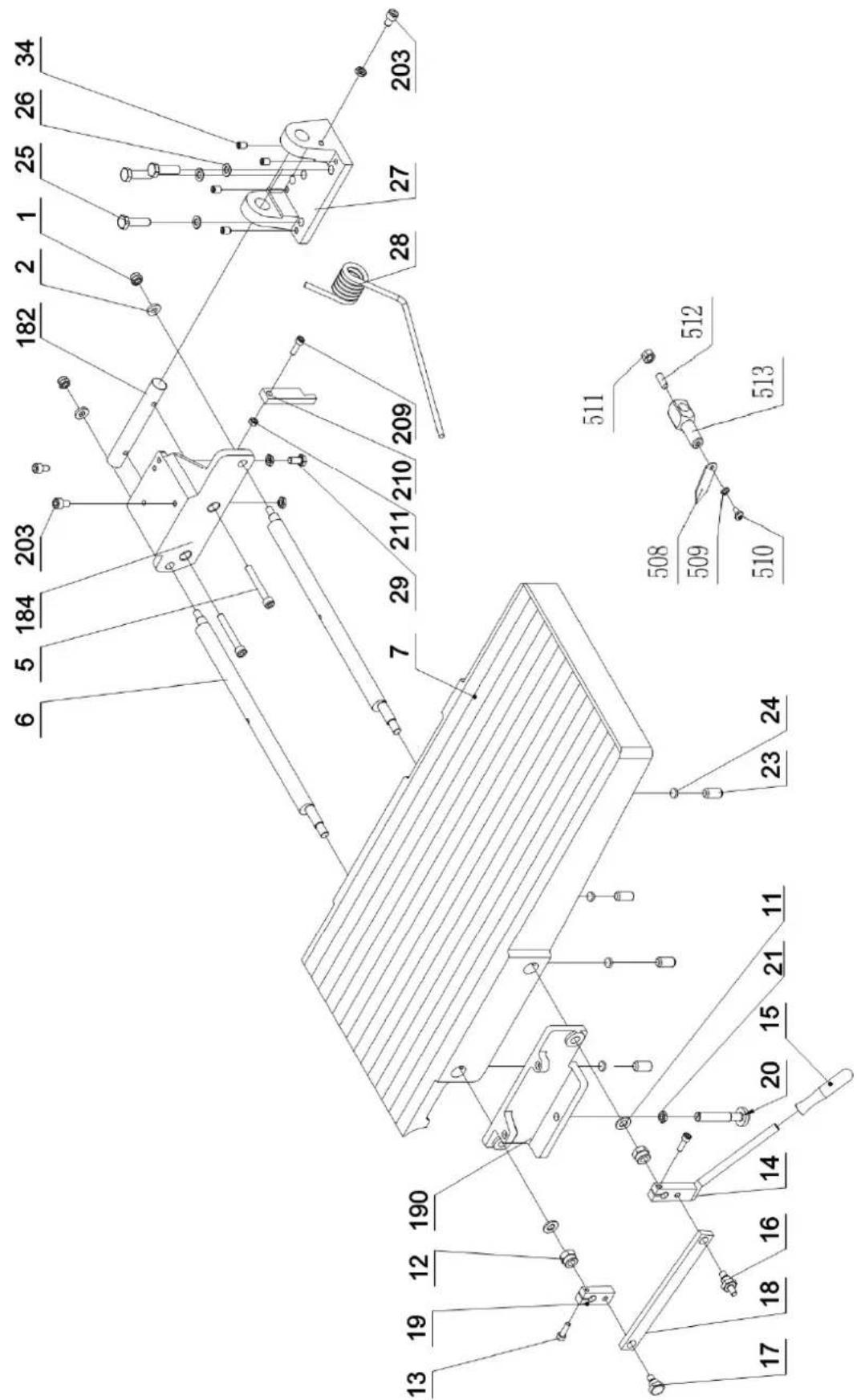
| Part number | Description | Size | Quantity |
| 1 | Lock | Nut | M8 |
| 2 | Thick | Washer | |
| 5 Hex. Socket Cap Screw M8X60 2 | |||
| 6 | Eccentric | shaft | |
| 7 | Front | Table | |
| 11 | Washer | 12 | |
| 12 | Hex. | Lock | Nut |
| 13 | Socket Cap Screw | M6X20 2 | |
| 14 | Adjusting handle | 1 | |
| 15 | Knob | 1 | |
| 16 | Bracket Screw | 1 | |
| 17 | Bracket Screw | 1 | |
| 18 | Eccentric Shaft Bracket | 1 | |
| 19 | Eccentric Shaft Clamp | 1 | |
| 20 | Table Locking shaft | 1 | |
| 21 | Hex. Thin Nut | M12 | 1 |
| 23 | Socket Set Screw | M8X10 4 | |
| 25 | Hex.Bolt | M8X30 | 3 |
| 26 | Washer | 8 | 3 |
| 27 | Table Support | 1 | |
| 28 | Spring | 1 | |
| 29 | Hex. Bolt | M8X16 | 1 |
| 34 | Socket Set Screw | M8X12 5 | |
| 182 | Outfeed Table Bracket Shaft | 1 | |
| 184 | Infeed Table Bracket Right | 1 | |
| 190 | Infeed Table Bracket Left | 1 | |
| 203 | Hex. Socket Cap Screw M8X16 2 | ||
| 209 | Hex. Socket Cap Screw M8X35 1 | ||
| 210 | Table Stopper | 1 | |
| 211 | Hex. Thin Nut | M8 | 1 |
| 508 | Pointer | 1 | |
| 509 | Spring washer | H4 | 1 |
| 510 | Screw | M4X8 | 1 |
| 511 | Hex. Nut | M6 | 1 |
| 512 | Set Screw | M6X16 | 1 |
| 513 | Support pole | 1 | |
| 529 | Plate | 1 | |
Planer thicknesser – drive and motor assembly
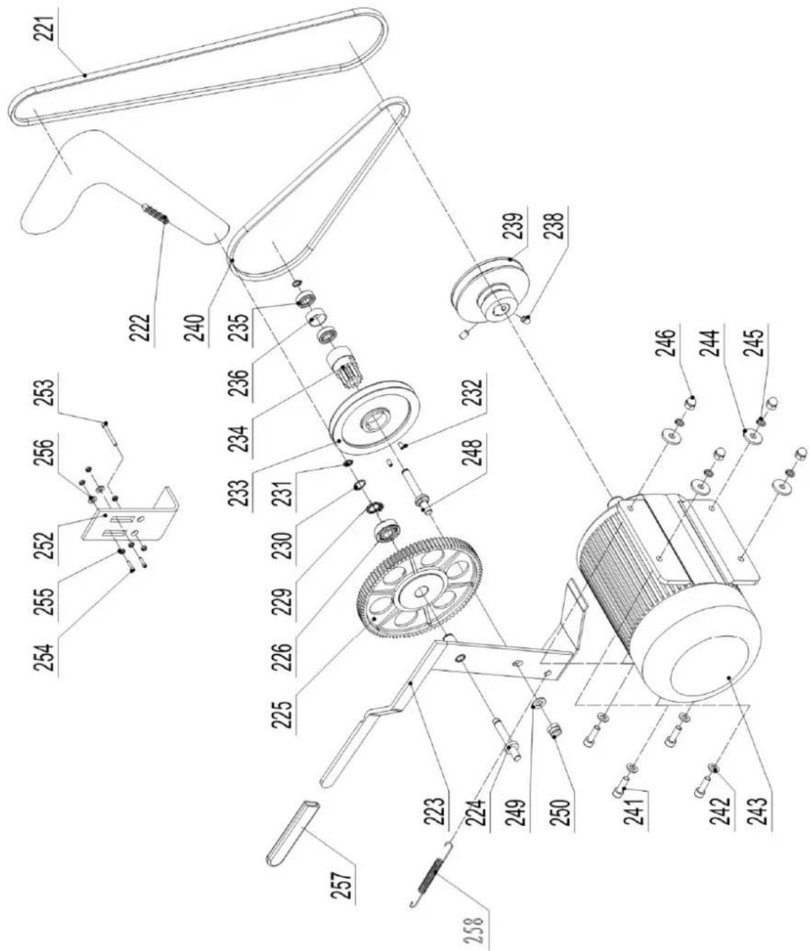
| Part number Description Size Quantity | |||
| 221 V-Belt for Cutterblock A1194 1 | |||
| 222 | Drive | Chain | 081-86 |
| 223 Cam Wheel Bracket 1 | |||
| 224 Cam Wheel Shaft 1 | |||
| 225 Plastic Gear Wheel Assembly 1 | |||
| 226 | Bearing | 61902 | 2 |
| 229 | Retaining Ring | 28 | 2 |
| 230 | Retaining Ring | CLP15 | 1 |
| 231 | Retaining Ring | CLP10 | 2 |
| 232 Hex. Socket Set Screw M5X10 2 | |||
| 233 V-Belt Pulley for Feed Roller 1 | |||
| 234 | Gear | Wheel | |
| 235 | Bearing | 6000-2Z | |
| 236 | Spacer | Bearing | |
| 238 Hex. Socket Set Screw M6X12 2 | |||
| 239 | Motor | Pulley | |
| 240 V-Belt for Feed Roller O-770E | 1 | ||
| 241 | Hex. Bolt | M8X25 | 4 |
| 243 | Motor 230/50/1 | 1 | |
| Motor 400/50/3 | 1 | ||
| 244 | Large Washer | 8 | 4 |
| 245 | Spring Washer | 8 | 4 |
| 246 | Cap | Hex. | Nut |
| 248 | Shaft | ||
| 249 | Washer | 10 | 1 |
| 250 | Hex. Lock Nut | M10 | 1 |
| 252 | Plate | ||
| 253 | Hex Bolt | M6x60 | 1 |
| 254 | Socket Cap Screw | M6x20 | 2 |
| 255 | Hex Nut | M6 | 6 |
| 257 | Rubber | Handle | |
| 258 | Tension Spring | ||
2
Planer thicknesser – thickness table assembly
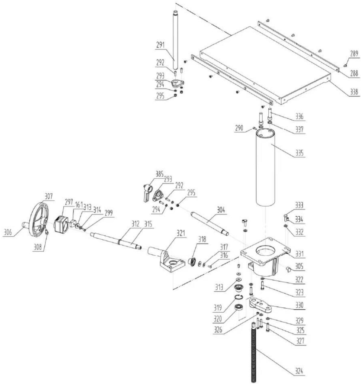
| Part number | Description | Size | Quantity |
| 161 | Indicator | Seat | |
| 288 | Long | Bar | |
| 289 | Screw | M6x10 | |
| 290 | Hex. Socket | Screw | |
| 291 Thickness Table Guide Bar 1 | |||
| 292 Hex. Socket Cap Screw M6x20 4 | |||
| 293 | Guide Bar Bracket | 2 | |
| 294 | Washer | 6 | 4 |
| 295 | Hex. Lock | Nut | |
| 297 | Position Indicator | ||
| 299 | Screw | M6x16 | |
| 304 | Locking Bar | ||
M6x
1
1
| 305 | Locking | Shoe | |
| 307 | Crank Handwheel | ||
| 308 Hex. Socket Cap Screw M8x16 1 | |||
| 312 | Retaining | Ring | CLP20 |
| 313 | Large | Washer | |
| 314 | Washer | 6 | |
| 315 | Crank | Bar | |
| 316 | Pan Head Screw | M6x12 2 | |
| 317 | Large | Washer | |
| 318 | Bevel Gear | ||
| 319 | Retaining | Ring | CLP35 |
| 320 | Bearing | 6202-2Z | 2 |
| 321 | Bevel Gear Bracket | 1 | |
| 322 | Washer | 8 | |
| 323 | Hex. Bolt | M8x35 | 2 |
| 324 | Thread Rod | ||
| 325 | Hex. Bolt | M6x50 | 1 |
| 326 | Hex. Nut | M6 | 1 |
| 327 | Hex. Bolt | M8x35 | 2 |
| 329 | Washer | 8 | |
| 330 | Thread Rob Bracket | ||
| 331 | Column Support | ||
| 332 | Washer | 8 | |
| 333 | Hex. Bolt | M8x25 | 4 |
| 334 | Hex. Socket Set Screw M8x12 4 | ||
| 335 | Column | ||
| 336 | Hex. Socket Screw | M12X45 | 2 |
| 337 | Spring | Washer | 12 |
| 338 | Thickness Table | ||
| 385 | Lock handle | ||
Planer thicknesser – working fence assembly
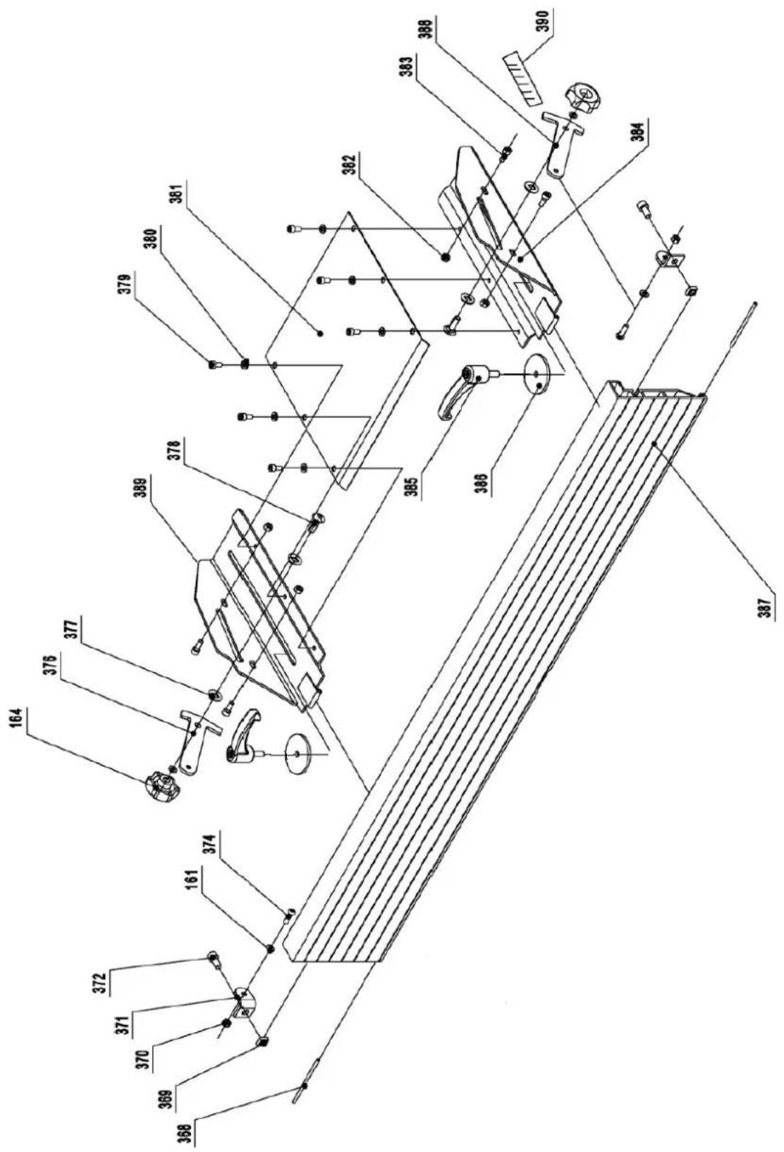
| Part number | Description | Size | Quantity |
| 161 | Large | Washer | |
| 164 | Lock | knob | |
| 368 Pin for Hinge 2 | |||
| 369 | Square | Nut | |
| 370 | Nut | M6 | |
| 371 | Fence Mounting | Bracket | |
| 372 | Hex. Socket | Screw | |
| 374 | Hex. Socket Cap Screw M6X16 | 2 | |
| 376 | Fence Support-Right | ||
| 377 | Nylon Washer | ||
| 378 | Carriage Bolt | M8X25 | 2 |
| 379 | Pan Head Screw | M6X12 | 6 |
| 380 | Washer | 6 | 6 |
| 381 | Cutterblock Cover | ||
| 382 | Hex. Nut | M6 | |
| 383 | Hex. Socket Cap Screw M6X10 | 4 | |
| 384 | Fence Bracket-Left | ||
| 385 | Lock Handle | ||
| 386 | Special Washer | ||
| 387 | Fence | ||
| 388 | Fence Support-Left | ||
| 389 | Fence Bracket-Right | ||
| 390 | Fence Scale | ||
M8X
1
4
1
1
2
2
1
1
1

natural_image
Technical line drawing of a mechanical machine with no visible text or symbolsnatural_image
Technical line drawing of a mechanical machine with no visible text or symbolsnatural_image
Technical line drawing of a mechanical assembly with gears and shafts (no text or symbols)natural_image
Technical line drawing of a mechanical device with rollers and mounting brackets (no text or symbols)natural_image
Line drawing of hands using a tool to cut or mark a piece of material on a workbench (no text or symbols)natural_image
Close-up of a white mechanical device on a perforated metal tray, with a hand partially visible (no text or symbols)Ciecie poprzeczne
natural_image
Close-up of a mechanical assembly with a white panel and metal frame (no visible text or symbols)Krawędź ścięta
natural_image
Industrial robotic arm operating a metal frame with a curved tool (no visible text or symbols)natural_image
Illustration of a person using a tool on a wooden beam, with no visible text or symbols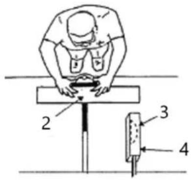
natural_image
Diagram showing a vertical structure with an arrow indicating direction, no text or symbols present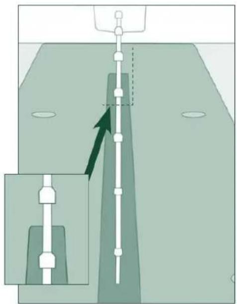
natural_image
Diagram showing a mechanical assembly with a vertical rod inserted into a housing, and an inset view of a component (no text or symbols present)natural_image
Technical line drawing of a mechanical assembly with labeled components A and B (no text or symbols beyond labels)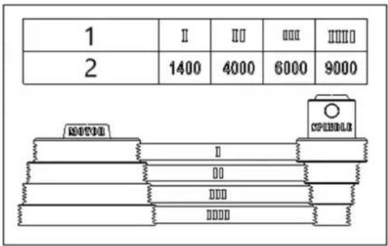
1- Krok prędkości
natural_image
Line drawing of a mechanical assembly with hands operating a tool (no text or symbols)Rysunek 4
1- Kołnierz
2- Nóž
natural_image
Illustration of hands using a tool on a wooden surface, with arrows indicating motion direction (no text or symbols)natural_image
Illustration of hands using a tool on a wooden plank, with inset showing mechanical components (no text or symbols)natural_image
Technical line drawing of a hand using a tool to adjust or install a grid-patterned component on a railway track (no text or symbols present)natural_image
Line drawing of a hand using a tool to cut or install a metal bracket (no text or symbols present)Rysunek 11
Rysunek 14
natural_image
Pure mechanical diagram showing a lever mechanism without any text, numbers, or symbolsnatural_image
Technical line drawing of a mechanical assembly with a hand pressing a component (no text or symbols)Rysunek 16
natural_image
Technical line drawing of a mechanical assembly with arrows indicating motion (no text or symbols)natural_image
Technical line drawing of a hand operating a mechanical assembly with tools (no text or symbols)natural_image
Close-up of a cylindrical mechanical component with a red arrow pointing to a hole, resting on a textured surface (no text or symbols visible)natural_image
Close-up of a mechanical component with a metallic shaft and circular base, featuring a red arrow pointing to a specific part (no text or symbols visible)natural_image
Close-up of a mechanical component with a red arrow pointing to a feature, no visible text or symbols.natural_image
Close-up of a mechanical component with red arrows pointing to features, no visible text or symbolsnatural_image
Close-up of a metallic mechanical component mounted on a circular base, with no visible text or symbols.Rysunek 21

natural_image
Technical line drawing of a mechanical machine assembly (no text or symbols visible)natural_image
Technical line drawing of a mechanical machine with no visible text or symbolsnatural_image
Technical line drawing of a mechanical assembly with gears and shafts (no text or symbols)natural_image
Technical line drawing of a mechanical device with rollers and mounting brackets (no text or symbols)natural_image
Diagram showing a mechanical component rolling down an inclined track with an upward arrow indicating motion (no text or symbols present)natural_image
Line drawing of hands using a tool to cut or mark a piece of wood, no text or symbols presentnatural_image
Close-up of a white mechanical device with a wooden base and perforated panel, no visible text or symbolsPříčné řezání
natural_image
Close-up of a white computer monitor with a keyboard and mouse, no visible text or symbolsZkosená hrana
natural_image
Diagram showing a vertical structure with an arrow indicating direction, no text or symbols present
natural_image
Diagram showing a vertical structure with arrows indicating direction, no text or symbols presentZměna rychlosti
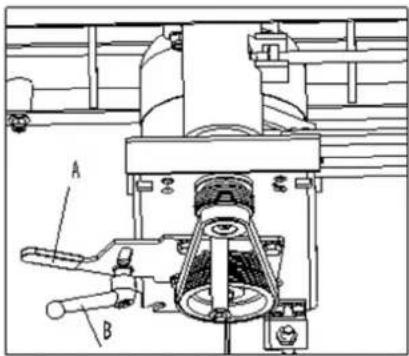
natural_image
Technical line drawing of a mechanical assembly with labeled components A and B (no text or symbols beyond labels)
natural_image
Line drawing of a hand operating a mechanical tool or device (no text or symbols present)Obrázek 4
natural_image
Illustration of hands using a tool on a wooden surface, with arrows indicating direction (no text or symbols)natural_image
Illustration of hands using a wooden plank to work on a wooden surface, with mechanical components and directional arrows (no text or symbols)natural_image
Technical line drawing of a hand using a tool to press or install a grid block on a railway track (no text or symbols present)natural_image
Line drawing of hands using a tool to cut or install a mechanical component (no text or symbols)Obrázek 11
Obrázek 14
natural_image
Pure mechanical assembly diagram without any text, numbers, or symbolsnatural_image
Technical line drawing of a mechanical assembly with a hand holding a tool, showing no text or symbols.Obrázek 16
natural_image
Technical line drawing of a wooden beam being lifted by a bracket (no text or symbols)natural_image
Technical line drawing of a mechanical assembly with hands operating a tool (no text or symbols present)natural_image
Close-up of a mechanical component with a red arrow pointing to a circular hole (no text or symbols visible)natural_image
Close-up of a mechanical component with a central shaft and circular base, featuring a red arrow pointing to a specific part (no text or symbols visible)natural_image
Close-up of a mechanical component with a bolted head and central hub, mounted on a circular base (no visible text or symbols)natural_image
Close-up of a mechanical component with red arrows pointing to features, no visible text or symbolsnatural_image
Close-up of a metallic mechanical component with a propeller, mounted on a circular base (no visible text or symbols)Obrázek 21

natural_image
Technical line drawing of a mechanical machine with no visible text or symbolsnatural_image
Technical line drawing of a mechanical machine with no visible text or symbolsnatural_image
Technical line drawing of a mechanical assembly with gears and mounting brackets (no text or symbols)natural_image
Technical line drawing of a mechanical device with rollers and mounting brackets (no text or symbols)natural_image
Line drawing of hands using a tool to cut or mark a piece on a surface (no text or symbols)natural_image
Close-up of a white manual cutting machine on a metal workbench, with a hand adjusting the blade (no visible text or symbols)Coupe transversale
natural_image
Close-up of a white office chair with a keyboard and hand resting on the floor (no visible text or symbols)Bord biseauté
natural_image
Illustration of a person using a tool on a wooden beam, with a scale and pointer (no text or symbols)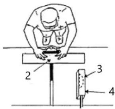
natural_image
Diagram showing a vertical structure with an arrow indicating direction, no text or symbols present
natural_image
Diagram showing a vertical structure with arrows indicating direction, no text or symbols present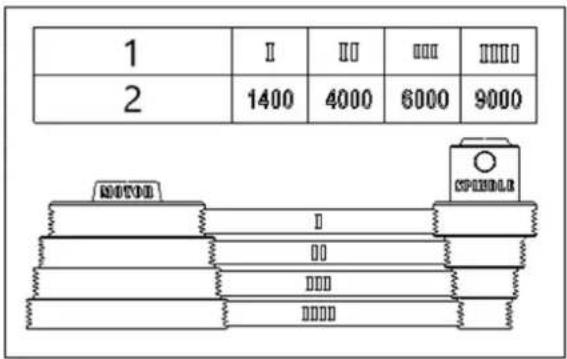
1- Étape de vitesse
2- Vitesse (RPM)
natural_image
Line drawing of a hand operating a mechanical tool or device (no text or symbols present)Figure 2
Figure 4
1- Collier
2- Cutter de table
3- Surface d'appui insuffisante
4- Travail
5- Tableau
6- Faux