DENGINE-9 - Generator MSW - Free user manual and instructions
Find the device manual for free DENGINE-9 MSW in PDF.

| Brand | MSW |
| Model | DENGINE-9 |
| Product type | Portable diesel generator |
| Engine type | Vertical single-cylinder 4-stroke diesel engine, air-cooled, direct injection |
| Maximum power | 8.2 kW |
| Rated power | 7.5 kW |
| Displacement | 456 cm³ |
| Rated speed | 3600 rpm |
| Fuel tank capacity | 5.5 L |
| Fuel consumption | 280 g/kWh |
| Oil tank capacity | 2.6 L |
| Weight | 48.6 kg |
| Dimensions (L x W x H) | 42 x 43 x 50 cm |
| Shaft diameter | 25.4 mm |
| Starting type | Manual recoil (pull) and electric optional |
| Recommended fuel | Light diesel (summer: #0, winter: #-10 or #-20) |
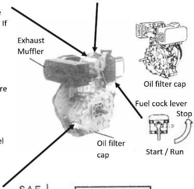
| Recommended engine oil | SAE 10W30, API CD quality or higher |
| Valve clearance (intake and exhaust) | 0.10-0.15 mm (cold) |
| Injection pressure | 20.5 ± 0.49 MPa (200 ± 5 kgf/cm²) |
| Oil change interval | First oil change after 20 h, then every 100 h or 3 months |
| Safety distance from buildings | At least 1 meter |
Frequently Asked Questions - DENGINE-9 MSW
User questions about DENGINE-9 MSW
0 question about this device. Answer the ones you know or ask your own.
Ask a new question about this device
Download the instructions for your Generator in PDF format for free! Find your manual DENGINE-9 - MSW and take your electronic device back in hand. On this page are published all the documents necessary for the use of your device. DENGINE-9 by MSW.
USER MANUAL DENGINE-9 MSW
natural_image
Orange and black industrial engine pump unit with visible branding and control buttons (no readable text or symbols)Einführung
natural_image
Technical line drawing of a mechanical device with no visible text or symbolsAbb. 1-1
natural_image
Mechanical device with labeled components and arrows indicating parts of motion (no readable text or symbols)Ölverschlußschraube
bar
| Wavelength (W) | Vorschlagswert (°C) | erlaubt Grenzwert (°C) | |---|---|---| | 10W | -20 | -10 | | 20W | -10 | 0 | | 30 | 0 | 10 | | 40 | 10 | 20 | | 50 | 20 | 30 | | 60 | 30 | 40 | | 70 | 40 | 50 | | 80 | 50 | 60 | | 90 | 60 | 70 | | 100 | 70 | 80 | | 110 | 80 | 90 | | 120 | 90 | 100 | The chart displays a horizontal bar chart comparing the SAE values for each wavelength range between the two geographies. The legend indicates that solid bars represent Vorschlagswert and dashed bars represent erlaubt Grenzwert. The x-axis is labeled with 'SAE' in degrees Celsius. There are no y-axis label provided in the image. The data is already in English.natural_image
Technical line drawing of a mechanical assembly with no visible text or symbolsnatural_image
Technical line drawing of a mechanical assembly with no visible text or symbolsnatural_image
Line drawing of a mechanical device with motion arrows indicating rotation (no text or symbols)natural_image
Mechanical diagram showing a lever mechanism with arrows indicating direction (no text or symbols present)natural_image
Mechanical component diagram with directional arrows indicating movement or force (no text or symbols)Kraftstoffsystem


This User Manual has been translated for your convenience using machine translation. Reasonable efforts have been made to provide an accurate translation; however, no automated translation is perfect nor is it intended to replace human translators. The official User Manual is the English version. Any discrepancies or differences created in the translation are not binding and have no legal effect for compliance or enforcement purposes. If any questions arise related to the accuracy of the information contained in the User Manual, please refer to the English version of those contents which is the official version.
CHAPTER 1: Technical specification and important information
Technical data
| Parameter description | Parameter value |
| Product name | Diesel Engine |
| Model | MSW-DENGINE-9 |
| Engine type | Single-Cylinder Vertical, 4-Stroke Air-Cooled Diesel Engine |
| Max power [kW] | 8.2 |
| Rated power [kW] | 7.5 |
| Displacement [cm3] | 456 |
| Rated speed [rpm] | 3600 |
| Bore x stroke [mm] | 88 x 75 |
| Fuel tank capacity [l] | 5.5 |
| Fuel consumption [g/kWh] | 280 |
| Oil tank capacity [l] | 2.6 |
| Shaft length [mm] | 71 |
| Shaft diameter [mm] | 25.4 |
| Dimensions (width x depth x height) [cm] | 42x43x50 |
| Weight [kg] | 48.6 |
natural_image
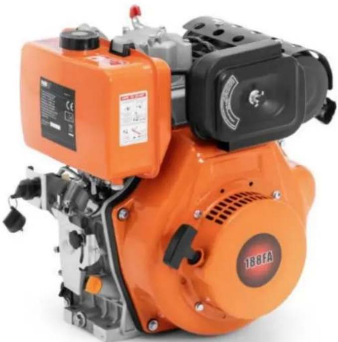
Orange and black diesel engine pump with visible branding and control panel (no text or symbols on main body)Introduction
Thank you for purchasing our product.
Our diesel engines feature the following:
• Direct injection combustion chamber
• Recoil-type manual starter with an optional electric starter
- Forced air cooling system
• Fan cover made from low-noise composite steel plate
These 4-stroke, air-cooled, direct injection diesel engines are designed to conserve materials and energy. They are compact, lightweight, easy to maintain, and convenient to transport. These engines are widely used in various applications, including industrial and agricultural machinery such as irrigation systems, sprayers, rice transplanters, threshers, grass cutters, soil samplers, as well as in equipment like vibration rammers, marine engines, light transport vehicles, mobile compressors, portable generators, car washing machines, and tillage machinery.
This manual provides detailed instructions on how to operate and maintain your engine. Please read the manual carefully before using the engine to ensure proper operation.
By following the guidelines in this manual, you can keep your engine in optimal condition and extend its service life.
If you have any questions or suggestions regarding this manual, please contact us or your dealer. Please note that as we continuously improve our products, the information in this manual may differ slightly from the actual product you received.
Safety information
Exhaust precautions
- Never inhale exhaust gas. It contains carbon monoxide, a colorless, odorless, and highly dangerous gas that can cause unconsciousness or death.
- Never operate the engine indoors or in poorly ventilated areas such as tunnels, caves, or enclosed spaces.
• Exercise extreme caution when operating the engine near people or animals. - Keep the exhaust pipe free from obstructions.
Refueling precautions
- Stop the engine before refueling.
• Do not overfill the fuel tank. - If fuel is spilled, wipe it up immediately and wait for it to dry completely before starting the engine.
- When changing the oil, ensure that the fuel cap is secure to prevent spillage.
Fire prevention
- Do not operate the engine while smoking or near open flames.
- Avoid using the engine near dry brush, twigs, rags, or any other flammable materials.
- Maintain a distance of at least 3 feet (1 meter) between the engine and any buildings or structures.
- Keep the engine away from flammable materials such as trash, rags, lubricants, or explosives.
Protective cover
- Ensure that protective covers are placed over all rotating parts. Exposed rotating components, such as the driving shaft, pulley, or belt, pose a hazard and should be shielded with protective covers or shrouds.
- Be cautious of hot parts. The muffler and other engine parts can become extremely hot during operation or shortly after stopping the engine.
- Operate the engine in a safe area and keep children away from the running engine.
Surroundings
- Operate the engine on a stable, level surface free of debris such as small rocks or loose gravel.
• Always keep the engine on a level surface. If the engine is tilted, fuel spillage may occur. - Note: Operating the engine on steep inclines may result in engine seizure due to improper lubrication, even if the oil level is at maximum.
- Take care to avoid fuel spillage when transporting the engine. Secure the fuel tank cap and close the fuel strainer cock before moving.
- Do not move the engine while it is running.
- If transporting the engine over long distances or on rough roads, drain the fuel from the tank to prevent leakage.
Pre-operation checks
- Thoroughly inspect fuel pipes and joints for looseness or fuel leaks, as leaked fuel can create a hazardous situation.
- Check all bolts and nuts for tightness. Loose bolts or nuts can lead to serious engine issues.
- Check the engine oil and refill if necessary.
- Check the fuel level and refill if needed, taking care not to overfill the tank.
- Wear snug-fitting work clothes when operating the engine. Avoid wearing loose garments like aprons, towels, or belts, as they may get caught in the engine or drive components, leading to a dangerous situation.
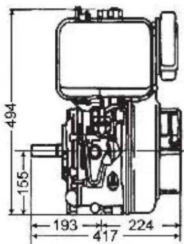
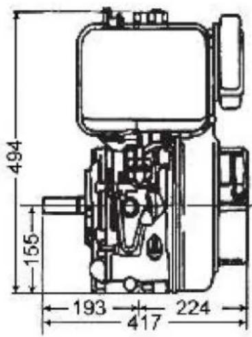
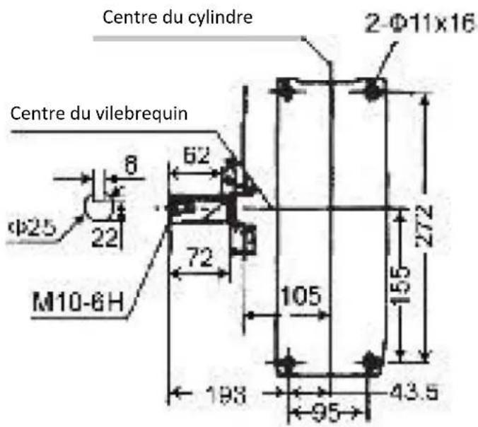
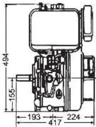
Overall Dimension and Installation
Overall Dimension
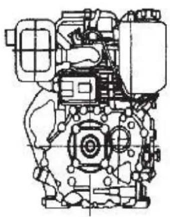
natural_image
Technical line drawing of a mechanical assembly (no text or symbols visible)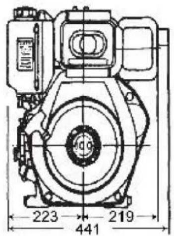


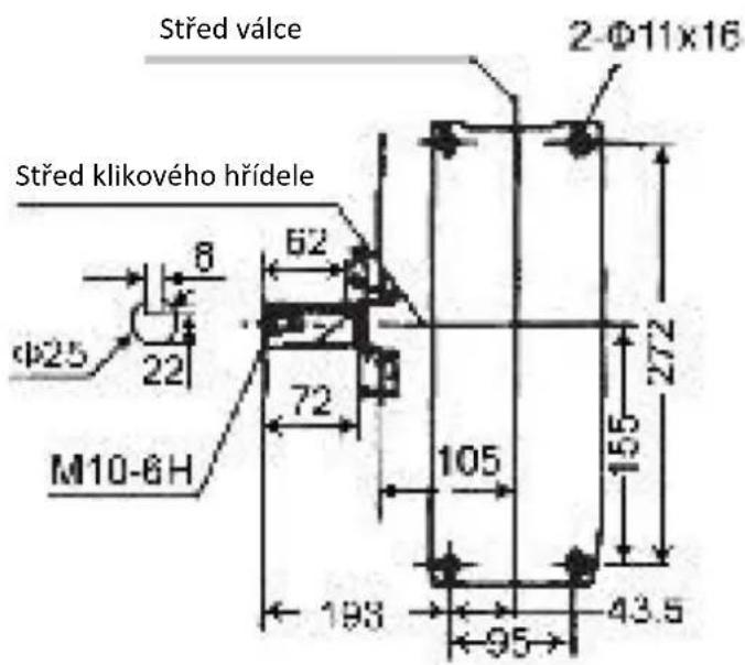
Installation
1) Ensure the diesel engine is mounted on a solid, stationary foundation to prevent vibration or movement during operation.
2) Verify that the center alignment of the output axle is correct.
3) Check if the calibration between the axle hole of the belt wheel and the keyway shaft is accurate and ensure that the tightening screw nut of the belt wheel is securely fastened.
4) When the engine is connected to other belt-driven machinery, ensure that the diameter of the driving wheel is compatible with the diesel engine's speed and the size of the axle wheel of the connected machine. Failure to do so can negatively affect the engine's performance, reduce its lifespan, and decrease the efficiency of the connected equipment.
The diameter of driving wheel (belt wheel) can be calculated as follow:
Diameter of engine driving wheel = (Diameter of axle of wheel of working machine * speed of working machine) / Diesel speed
5) Ensure the belt is properly tensioned.
- If the belt is too tight, the engine will be overloaded during startup, the belt will stretch excessively, and the engine may be damaged.
- If the belt is too loose, it will slip during high-speed or high-load operation, reducing performance and potentially causing damage.
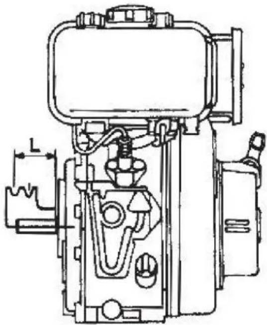
Allowed distance between belt wheel and engine:
- The V-axle wheel groove should be as close to the engine as possible. The allowed distance "L" is specified in the table below.
- Note: The meaning of "L" is shown in the figure above. Please contact us or your dealer if you have any questions.
| Belt type | B |
| Belt quantity | 2 |
| Minimal diameter of pulley | 135 |
| L | ≤70 mm |
Table 1-1
natural_image
Technical line drawing of a mechanical device with no visible text or symbols• Crankshaft (Original type) driving angle must be less than 120°, see Fig.1-1
• The tilt must be kept within the allowed value shown in Fig.1-2
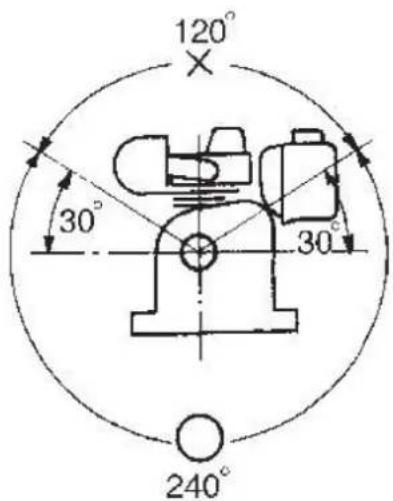
Fig 1-1
| Output shaft tilt | 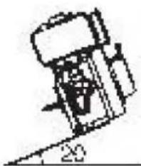 | 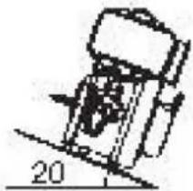 |
| Allowed tilt (continuous running) | ≤ 20^ | |
| Engine tilt | 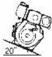 | 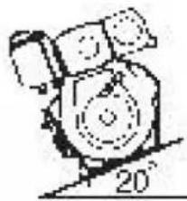 |
| Allowed tilt (Continuous running) | ≤ 20^ | |
Fig 1-2
- Please contact out dealer about electric circuit
It is recommend to use accumulators with a capacity of 36-45 Ah (rated for 20 hours).
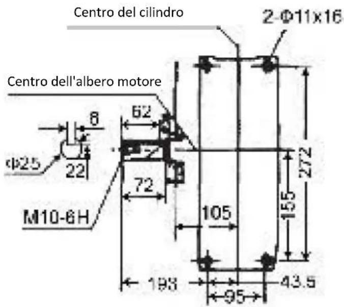
Connecting Sizes
Sizes of output shaft
Keyway shaft:
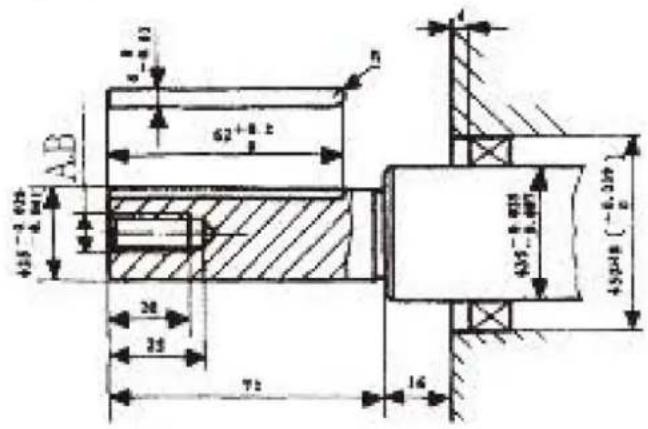
Thread shaft:
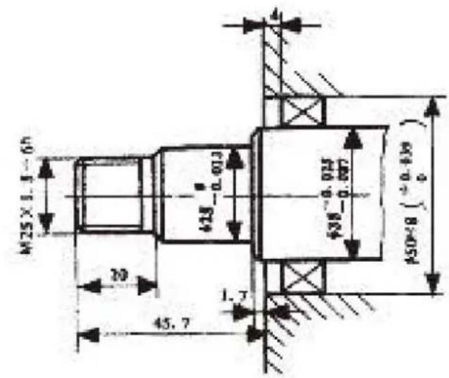
Taper shaft:
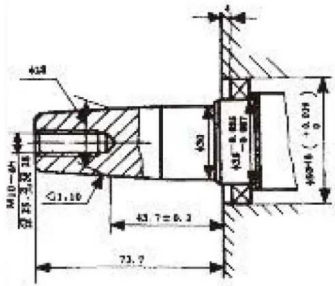
Sizes of PTO flanges
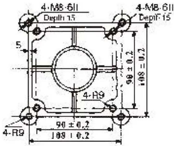
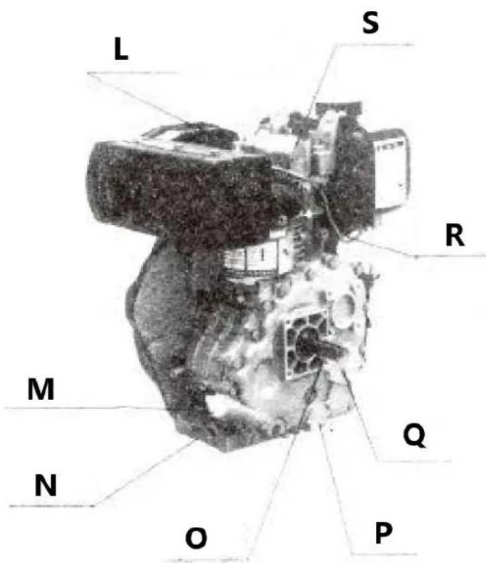
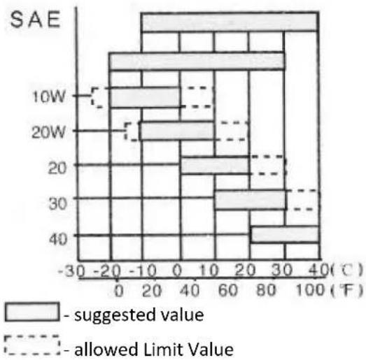
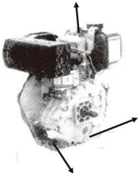
Names of Diesel Engine Parts
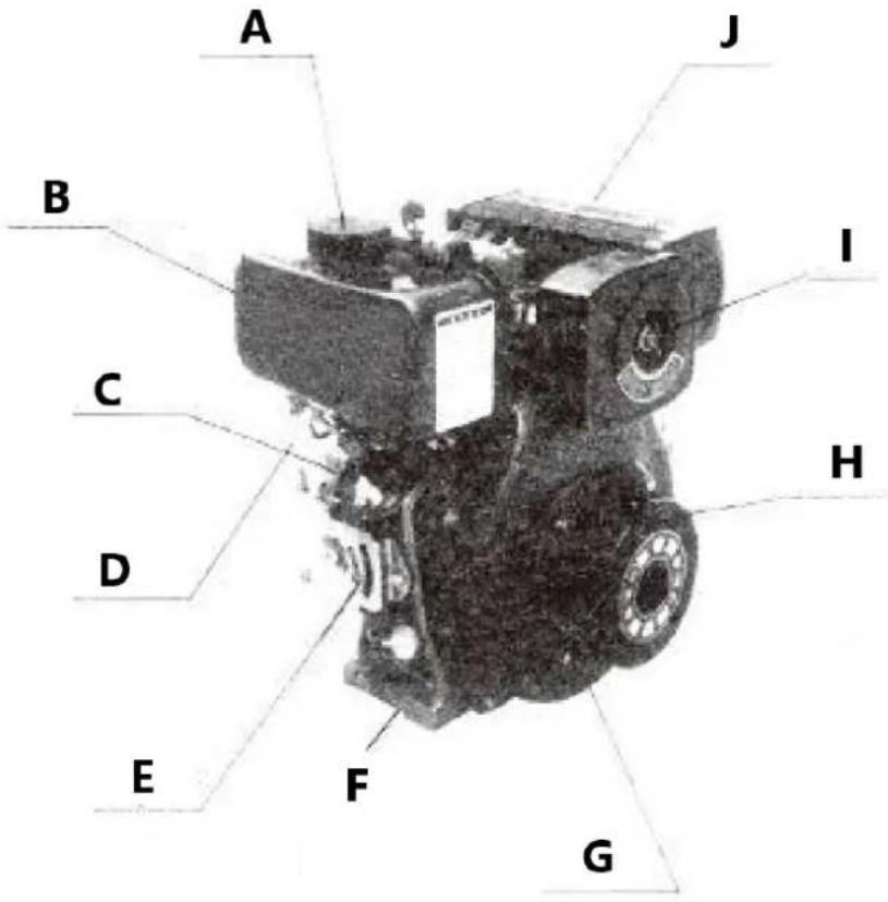

A - Cap
B - Fuel Tank
C - Fuel Pump
D - Fuel Cock
E - Speed Governor System
F - Oil Outlet
G - Recoil Manual Starter
H - Cover of Wind
I - Air-Cleaner
J - Exhaust Muffler
K - Fuel Injection Nozzle
L - Oil Depth Gauge and Inlet Port
M - Oil Outlet
N - Crankshaft Output
O - Oil Filter
P - Oil Pump
Q - High Pressure Fuel Pipe
R - Decompression Lever
Valve open and close phase, initial angle of fuel delivery and valve clearance.
Valve open and close phase (CA - Crank angle)
| Intake valve open [CA] | BTDC13° |
| Intake valve close [CA] | ATDC52° |
| Exhaust vaJve open [CA] | BBDC57° |
| Exhaust vaJve close [CA] | ABDC8.5° |
Table 1-3
Initial angle of fuel delivery
| Crank angle | 22^ ± 1^ |
Table 1-4
Valve clearance
| Intake valve [mm] | 0.10-0.15 (Cold state) |
| Exhaust valve [mm] | 0.10-0.15 (Cold state) |
Table 1-5
Range of temperature smoke and pressure
| Exhaust temperature(°C) | ≤550 |
| Machine oil temperature (°C) | ≤120 |
| Smoke (Boach) | ≤4 |
| Pressure ol injection Mpa (kgf/cm2) | 20.5 ± 0.49(200 ± 5) |
Table 1-6
Torque for Tighten Up Main Screw Bolt and Nut
| Connecting rod nut [Nm] | 40-45 |
| Cylinder head nut [Nm] | 55-60 |
| Flywheel nut [Nm] | 160-170 |
| Nozzle retainer nut [Nm] | 10-12 |
| Tighten bolt of rocker support [Nm] | 25-30 |
| Standard MB bott [Nm] | 20-30 |
| Standard M6 bott [Nm] | 15-20 |
| Note: Retighten up after test period | |
Table 1-7
CHAPTER 2: Operation of diesel engine
Safety precautions:
- Filter fuel using silk fabric or let it settle for 24 hours before use. Do not add oil to the fuel tank or crankshaft case while the engine is running.
- Keep flammable and explosive materials away from the engine. Ensure the installation area is flat and well-ventilated.
- Avoid touching the muffler when the engine is running or just after stopping, as it can be very hot.
- Operate the engine at its rated power and speed. If any abnormal conditions occur, stop the engine immediately to inspect and resolve the issue.
- For new or newly serviced engines, run at low speed and low load for the first 20 hours. Avoid operating at high speed or full load during this break-in period.
Choice of fuel, oil and preparation before start
Choice of fuel:
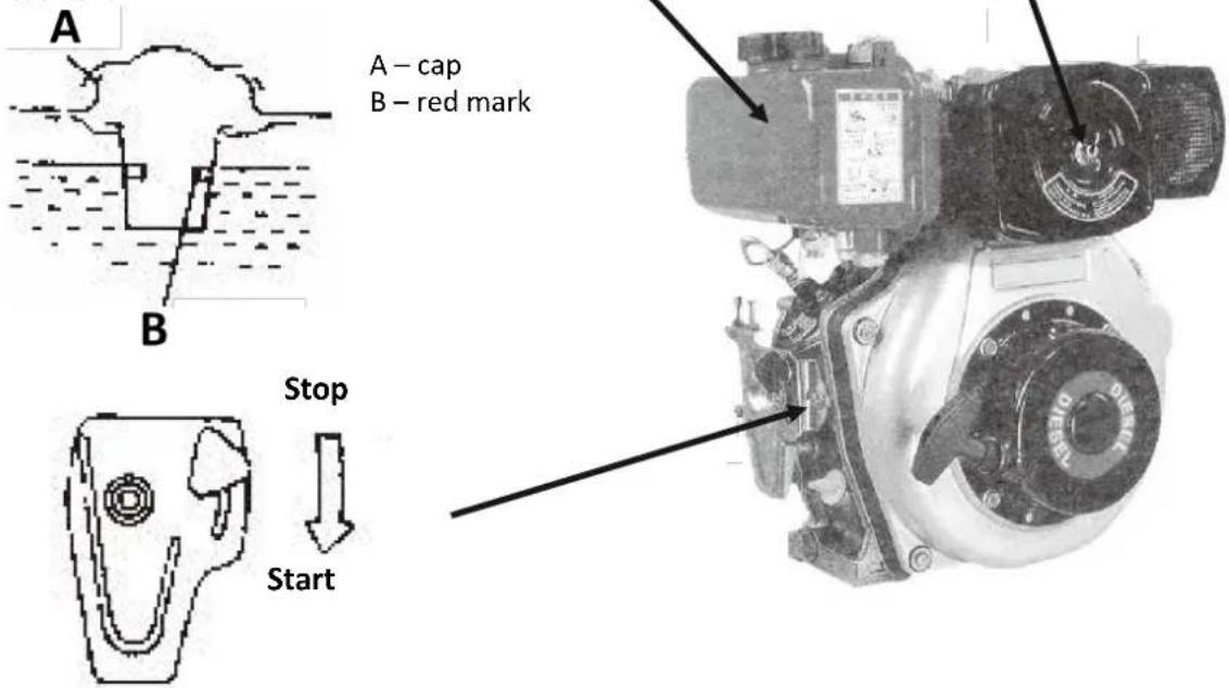
Use only light diesel fuel for the diesel engine. For summer, use No. 0 diesel; for winter, use No. -10 or No. -20 diesel, depending on the temperature. Ensure no dust or water enters the fuel or fuel tank.
Fuel capacity: 5.5 liters
Caution: Do not fill the fuel above the red mark.
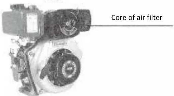
Air filter core:
Do not wash the air filter core, as it is a dry-type filter. Replace the core if engine performance decreases or if the exhaust color appears abnormal. Never operate the engine without the air filter core installed.
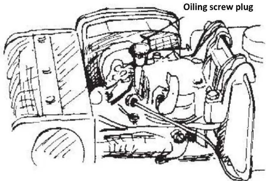
Oiling screw plug
In winter, if the engine is difficult to start, remove the plug and add 2cc of lube oil into the hole, then securely reinsert the plug. Ensure the plug is tightly fastened. If the plug is left out, the engine may absorb dust and become damaged.
Fuel and oil preparation
The fuel and engine oil were drained before shipment from the factory. Before refilling fuel and starting the engine, check the fuel pipeline. If there is air in the pipeline, it must be removed. To do this, loosen the nut at the connection between the injection pump and the fuel pipe, and bleed the air from the system until no bubbles are visible in the fuel.
Oil inlet:
Place the engine on level ground before filling oil into the inlet. When checking the oil level, insert the dipstick into the inlet gently without twisting it.
Oil tank capacity: 1.65 liters
Decompression lever:
Push decompression lever down to start the machine
bar
| Power Level | SAE (°C) | Allowed Limit Value (°C) | |-------------|----------|--------------------------| | 10W | -20 | 0 | | 10W | 0 | 20 | | 10W | 20 | 40 | | 10W | 40 | 60 | | 20W | -20 | 0 | | 20W | 0 | 20 | | 20W | 20 | 40 | | 20W | 40 | 60 | | 30W | -20 | 0 | | 30W | 0 | 20 | | 30W | 20 | 40 | | 30W | 40 | 60 | | 40W | -20 | 0 | | 40W | 0 | 20 | | 40W | 20 | 40 | | 40W | 40 | 60 |Ba sure to use SAE 10W30, API grade CD or higher.
Engine break-in period
If your engine is new, its lifespan could be shortened by overloading. During the first 20 hours of operation, follow the test run procedures for starting and stopping the engine.
- Avoid overloading: Do not overload the engine during the test run.
Oil change schedule
- Change the engine oil after the first 20 hours of operation or at the end of the first month during the break-in period.
- After that, change the oil every three months or every 100 hours of use, whichever comes first.
Interval of changing machine oil
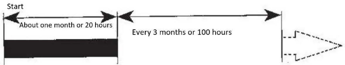
flowchart
graph LR
    A["Start"] --> B["About one month or 20 hours"]
    B --> C["Every 3 months or 100 hours"]
    C --> D["Geometric representation"]
Start of the Diesel Engine
Recoil start
Note: When the engine is running, no not pull the recoil handle otherwise the engine may be damaged.
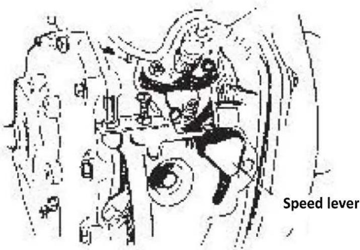
1) Open the fuel cock.
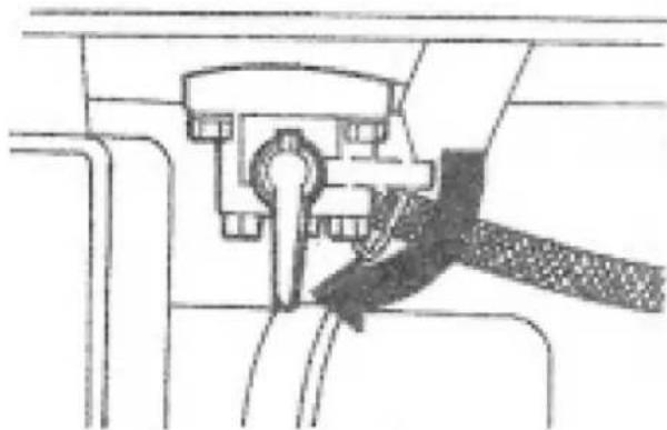
natural_image
Mechanical assembly diagram showing a lever mechanism with no visible text or symbols2) Put the engine speed lever in the "RUN" position
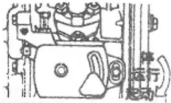
natural_image
Technical line drawing of a mechanical assembly with no visible text or symbols3) Initial pull on the starter rope
- Hold the starting handle firmly
- First pull the starting handle slowly, until you feel resistance
- Then return it slowly
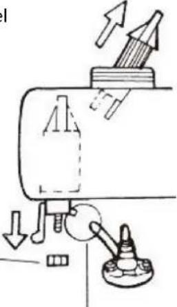
4) Push the decompression lever down and release.
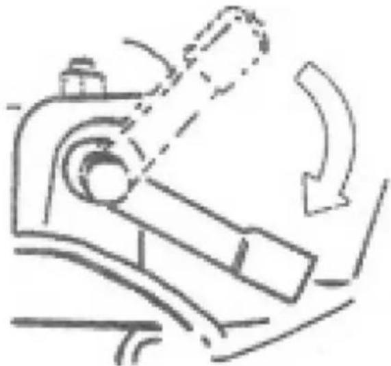
natural_image
Line drawing of a mechanical device with motion arrows indicating movement (no text or symbols)5) Pull the rope hard and fast. Pull it all the way out. Use two hands if necessary.
6) The engine should start. If the engine does not start, start again from step 3.
Motor-driven type start
1. Motor start
The preparation of motor-driven start type is same as manual type (Recoil type).
1) Open the fuel cock.
2) Set the speed governor lever at "start" position.
3) Turn on the start switch toward clockwise to "start" position.
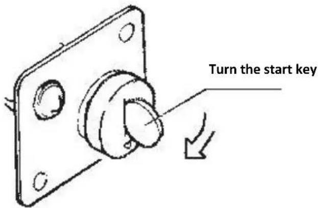
4) When the engine is started, take your hand away from key switch immediately.
5) If the engine does not start after 10 seconds, wait for a while (about 15 seconds) then start again.
NOTE:
- If the run time of motor is too long, the voltage of accumulator will drop and the motor may be damaged.
- Keep key switch et• ON n position when the engine is running
2. Accumulator
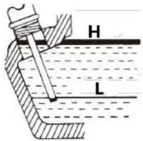
Check the liquid level in accumulator every month, if the level is lower than the low limit mark, refill distilled water up to the upper limit mark.
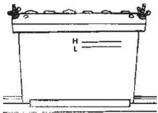
H - high
L - low
If the liquid in the accumulator is not enough, the electric motor will not run for too little electric current. So, keep the liquid level between upper and low limit marks. The liquid will splash on near parts (which will be spoiled) if it is too much in the accumulator.
Aided start
If the engine is difficult to start in winter, take off the rubber seal plug and then fill 2cc machine oil into the hole.
Notice:
Engine supplied to the torrid zone will not attach the rubber plug.(a solid plug is presented only)
WARNING:
- Do not use volatile liquid as fuel, such as gasoline etc., and do not take away the air cleaner for easy start of the engine, if you do so, it may cause explosion.
- Do not pull out the plug unless filling oil, if plug is not at its correct position, rain, dust or other impurity may be sucked into the engine to cause serious failure or to damage engine parts.
Run and Stop of the Diesel Engine
Run of the engine
1) Preheat the machine for three minutes at no load.
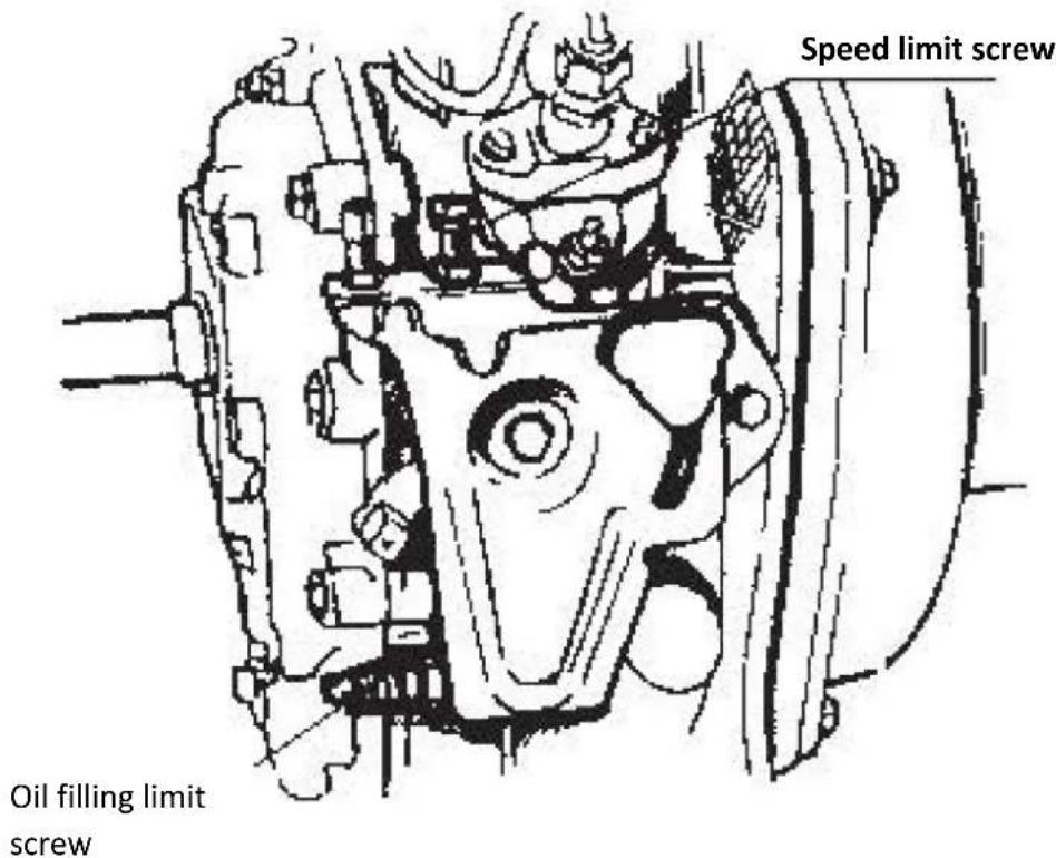
2) Set the Speed governor lever of the engine at required speed position.
Use the speed governor lever to control the speed of engine.
Do not loosen or readjust the limit screw of speed or oil-filling limit screw, otherwise the performance of the machine may be changed.
Check, when the machine Is running
1) Whether there is abnormal sound and vibration?
2) Whether combustion is not good or overspeed?
3) Whether the color of exhaust gas is normal (black or too white)?
If any of above phenomena is detected, stop the engine immediately and contact our local dealer.
Stop of the engine
1) At first set the speed governor lever at low position before stopping the engine, and run the engine at no-load for three minutes.
2) Set the speed governor lever at "stop" position.
Decrease the load gradually when stopping the engine. Sudden stop of engine will cause abnormal increasement of temperature. Do not stop engine with decompression lever.
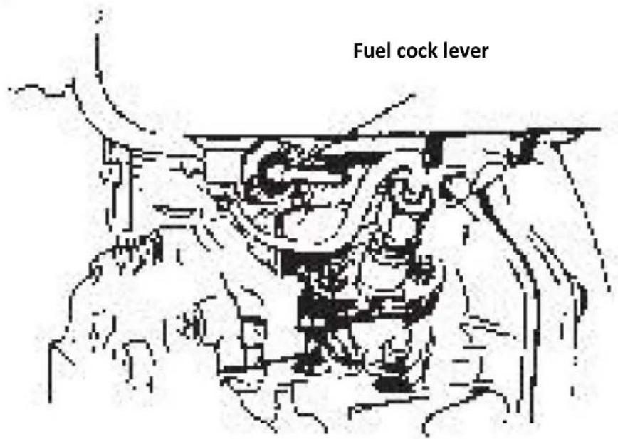
3) Set the fuel cock at "S" (stop position)
4) If the engine possesses motor type starter, turn the start key switch to "OFF" position.
5) Pull out the recoil handle slowly until pressure is felt by your hand (that means at the point of compression stroke, where the intake and exhaust valves are closed) and then let the handle back to its natural position so that it can prevent rust when the engine is not used.
Note: Only when stopping the engine can you pull the recoil handle, otherwise the engine may be damaged.
CHAPTER 3: Technical maintenance of diesel engine
Daily check and maintenance
- Check that the machine oil level is between the upper and lower limits.
• Inspect for any signs of oil leakage. - Clean dirt, grease, and dust from the diesel engine and its components to keep the engine clean.
- Address any malfunctions detected during operation.
Regular check and maintenance
Regular checks and maintenance are essential for the engine's normal operation and long-term durability. The table below outlines the necessary maintenance tasks and their intervals. Tasks marked with a symbol indicate that special tools or techniques are required. For these, please contact your local dealer.
| Item \ Time Daily | After 20 hours or 1 month | 100 Hours or Every 3 months | 500 Hours or Every 6 months | 1000 Hours or Every year | |
| Check and tighten the nut and screw | ○ | ||||
| Check and fill machine oil | ○ | ||||
| Change machine oil | ○(First time) | ○(Second time and later) | |||
| Clean and change oil filter | ○ | ●(Change) | |||
| Check oil-leakage | ○ | ||||
| Change the core of air filter | Cycle of check and maintenance will be shortened at dusty places | ○ | |||
| Clean fuel tank | Every month | ||||
| Clean or change fuel filter | ○(Clean) | ○(Change) | |||
| Check nozzle | ● | ||||
| Check injection pump | ● | ||||
| Check pipeline of fuel | ○(Change if necessary) | ||||
| Adjust valve clearance of inlet and exhaust | ●(First time) | ● | |||
| Grind valve holder of inlet and exhaust | ● | ||||
| Change piston ring | ● | ||||
| Check accumulator liquid | Each month | ||||
| Clean the core of air filter | (Clean every month or 50 hours) | ||||
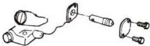
Clean and change fuel filter The fuel filter must be kept clean day-to-day to guarantee max output of the engine Take the filter out of fuel tank and clean it
| Clean | Every six months or 500 hours |
| Change | Every year or 1000 hours |
Pull out filter
natural_image
Pure mechanical diagram showing a valve mechanism with arrows indicating direction (no text or symbols)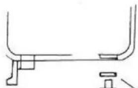
natural_image
Simple line drawing of a mechanical support structure with no text or symbolsLoosen nut and take it out
Loosen fuel screw
Drain out fuel
Take off high pressure fuel pump
natural_image
3D mechanical component with directional arrows indicating movement or force (no visible text or symbols)Change Lube oil filter
| Clean | Every six months or 500 hours |
| Change | Every year or 1000 hours |
natural_image
Technical line drawing of a mechanical device with two connectors and a cable (no text or symbols)
Capacity: 1.65l
Change: Operating period
First: First month or after 20 hours
Second and later: Every 3 months or 100 hours
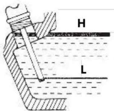
H - High limit
L - Low limit
Change the core of air filter
- Change every 6 months or 500 hours (earlier if necessary).
Important note: Do not use detergent to clean filter core. Use a soft brush instead.
The core of filter obstruction means that the air in the combustion chamber will decrease, and then the output of engine decreases, and consumption of fuel and lubricant increases. It is also difficult to start the engine. Clean the core of filter regularly.
Storage for a long period
Follow these steps if storing the engine for an extended period:
1) Run the engine for three minutes, then stop it.
2) Drain the lubricant while the engine is still warm, and refill with new machine oil.
3) Remove the rubber plug on the rocker shaft cover, add about 2cc of lubricant, and then replace the plug.
4) For recoil start type:
- Push down the decompression lever to the non-compression position, then pull the recoil starter two or three times.
For motor-driven start type:
- Set the decompression lever to the non-compression position, then rotate the engine for two to three seconds using the start key (do not run the engine).
5) Pull up the decompression lever and slowly pull the recoil starter until resistance is felt (this indicates the compression stroke, where the intake and exhaust valves are closed, helping to prevent engine rust).
6) Clean off any dirt and oil from the engine, and store it in a dry place.
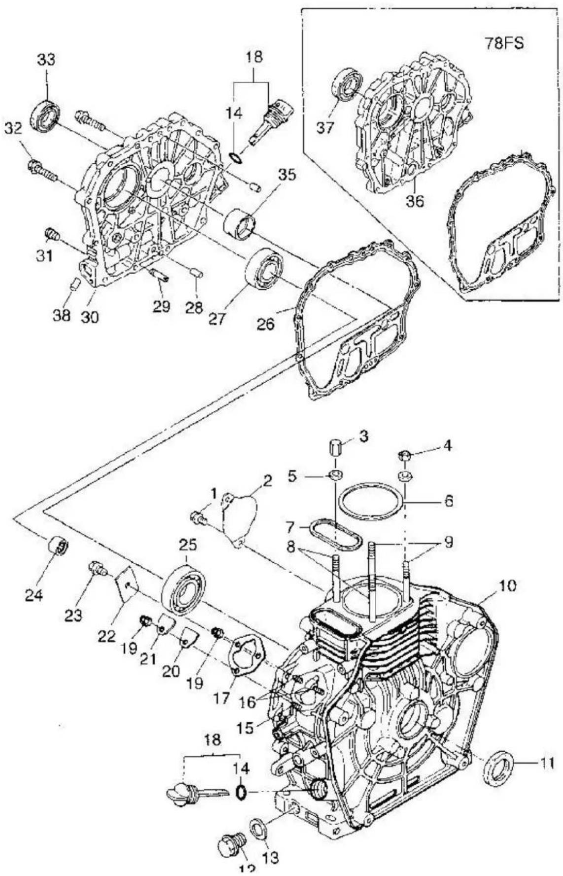
CHAPTER 4: Parts list of diesel engine
| Number | Name of part | Quantity |
| 1 | Bolt M10*20 | 2 |
| 2 | Cover of starting motor hole | 2 |
| 3 | Nut of cylinder head (long) | 2 |
| 4 | Nut of cylinder head (short) | 2 |
| 5 | Gasket of nut of cylinder head | 2 |
| 6 | Gasket of cylinder head (0.4) | 1 |
| 7 | Rectangle ring 5.1*2.5 | 1 |
| 8 | Bolt of cylinder head (long) | 2 |
| 9 | Bolt of cylinder head (short) | 2 |
| 10 | Cylinder block | 1 |
| 11 | Raed oil sealing 35 × 50 × 8 | 1 |
| 12 | Cock of oil draining | 1 |
| 13 | Gasket of cock of oil draining | 1 |
| 14 | "O" type ring 24.2 × 4 | 2 |
| 15 | Fastening bolt of fuel injection pump (short) | 1 |
| 16 | Fastening bolt of fuel injection pump (long) | 2 |
| 17 | Adjusting gasket of fuel injector (0.5) | 1 |
| 18 | Dipstick of lubricating oil | 2 |
| 19 | Nut M6 | 3 |
| 20 | Gasket of sealing plate | 1 |
| 21 | Sealing plate | 1 |
| 22 | Thrust piece | 1 |
| 23 | Bolt with flange face M8 × 14 | 1 |
| 24 | Needle bearing 7941/15 | 1 |
| 25 | Ball bearina 308CGB/T276-94) | 1 |
| 26 | Gasket of crankcase cover | 1 |
| 27 | Bearing 207(GB/T276-94) | 1 |
| 28 | Retaining pin 8 × 12 (GB119-86) | 2 |
| 29 | Fuel pipe | 1 |
| 30 | Crankcase cover | 1 |
| 31 | Inner hexagon plug G1/8" | 1 |
| 32 | Anti-loosing bolt M8 × 33.5 | 16 |
| 34 | Front oil sealing 35 × 50 × 10 | 1 |
| 35 | Main bush | 1 |
| 36 | FS crankcase cover | 1 |
| 37 | FS front oil sealing | 8 |
| 38 | AL plug Φ8 × 8 | 3 |
Note:
• The parts of the cylinder block include 1, 2, 8, 9, 10, 12, 13, 14, 15, 16, 18, and 24.
• The parts of the crankcase cover include 14, 18, 27, 28, 29, 30, 31, 35, and 38.
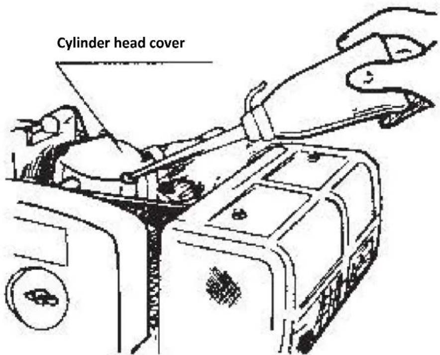
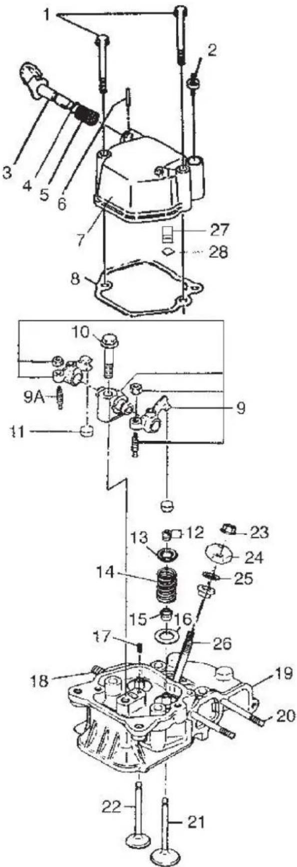
Cylinder head cover and cylinder head assembly
| Number | Name of part | Quantity |
| 1 | Bolt with flange face M6 × 70 (GB5789-86) | 2 |
| 2 | Oiling screw plug | 1 |
| 3 | Part of decompression shaft | 1 |
| 4 | O-ring 10 × 1.9 (GB1235-76) | 1 |
| 5 | Decompression spring | 1 |
| 6 | Retaining pin 3 × 16 (GB119-86) | 1 |
| 7 | Cylinder head cover | 1 |
| 8 | Gasket of cylinder head cover | 1 |
| 9 | Rocker arm | 1 |
| 9A | Adjusting screw of valve gap | 2 |
| 10 | Fastened bolt of rocker arm shaft | 1 |
| 11 | Valve adjusting packing | 2 |
| 12 | Valve clip | 4 |
| 13 | Valve spring seat | 2 |
| 14 | Valve spring | 2 |
| 15 | Oil seal of valve guide | 2 |
| 16 | Spring washer of valve | 2 |
| 17 | Pin4 × 8 (GB119-86) | 1 |
| 18 | Double ends stud AM8 × 20 (GB899-88) | 2 |
| 19 | Mechanical process parts of cylinder head | 1 |
| 20 | Double ends bolt AM6 × 75 (GB900-88) | 2 |
| 21 | Intake valve | 1 |
| 22 | Exhaust valve | 1 |
| 23 | Nut M6 (GB6177-86) | 2 |
| 24 | Press plate of fuel injector | 1 |
| 25 | Adjusting gasket of fuel injector | 1 |
| 26 | Fastened bolt of fuel injector(long) | 2 |
| 27 | Breather assembly | 1 |
| 28 | "O" type ring 12 × 1.9 | 1 |
Note:
• The cylinder head cover includes parts 2, 3, 4, 5, 6, 7, 27, 28, and 29.
• The rocker arm assembly includes parts 9 and 9A.
• The cylinder head includes parts 12, 13, 14, 15, 16, 17, 18, 19, 20, 22, and 26.
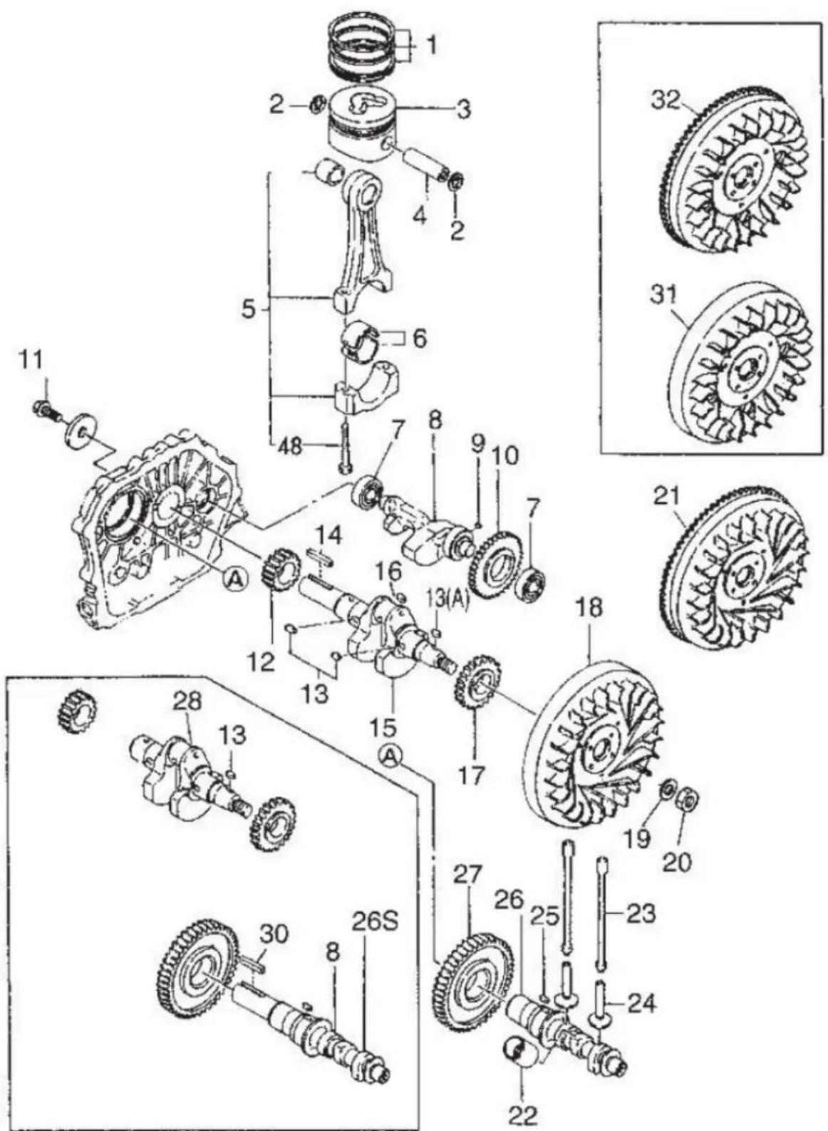
Piston connecting rod and crankshaft balancing mechanism
| Number | Name of part | Quantity |
| 1 | Piston ring group | 1 |
| 2 | Retainer of piston pin Φ23 | 2 |
| 3 | Piston | 1 |
| 4 | Piston pin | 1 |
| 5 | Connecting rod body | 1 |
| 6 | Connecting rod bush | 1 |
| 7 | Bearing 203 (GB/T276-94) | 2 |
| 8 | Balancing shaft | 1 |
| 9 | Key 5 × 7 (GB1096-79) | 2 |
| 10 | Balancing shaft timing gear | 1 |
| 11 | Bolt (for F shaft accompany with the diesel engine) | 1 |
| 12 | Crankshaft timing gear | 1 |
| 13 | Key 5 × 12 (GB1096-79) | 1 |
| 13A | Key 5 × 14 (GB1096-79) | 1 |
| 14 | Key 6 × 63 (GB1096-79) | 1 |
| 15 | Crankshaft | 1 |
| 16 | Plug 6 × 8 | 1 |
| 17 | Driving gear of balancing shaft | 1 |
| 18 | Flywheel | 1 |
| 19 | Gasket for nut of flywheel | 1 |
| 20 | Nut flywheel | 1 |
| 21 | Gear ring of flywheel (for starting motor) | 1 |
| 22 | Sleeve of fuel pump tappet | 1 |
| 23 | Push rod | 2 |
| 24 | Tappet | 2 |
| 25 | Key 5 × 14 (GB1096-79) | 2 |
| 26 | Camshaft | 1 |
| 26s | FS camshaft | 1 |
| 27 | Camshaft timing gear | 1 |
| 28 | FS crankshaft | 1 |
| 30 | Key 8 × 45 (GB1096-79) output of camshaft | 1 |
| 31 | FS flywheel | 1 |
| 32 | FS gear ring of flywheel | 1 |
Note:
• The parts of piston connecting rod include 1, 2, 3, 4, 5, and 6.
• The parts of balancing shaft include 8, 9, and 10.
• The parts of crankshaft include 9, 12, 13, 15, and 17.
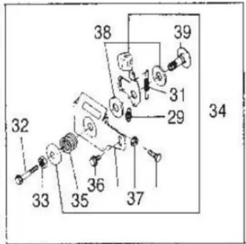
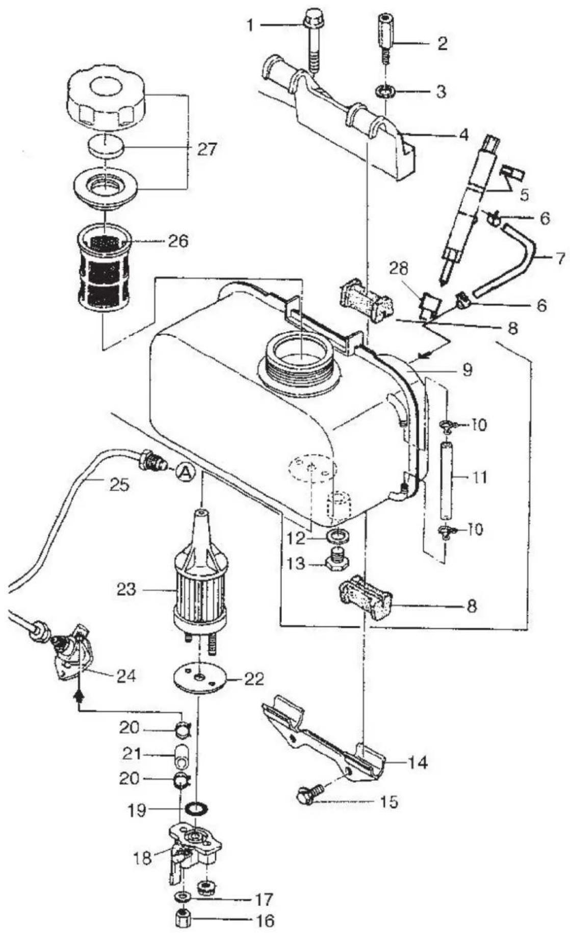
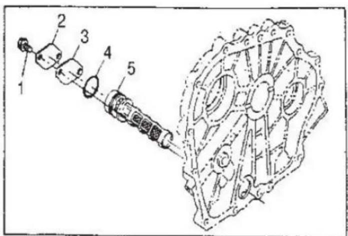
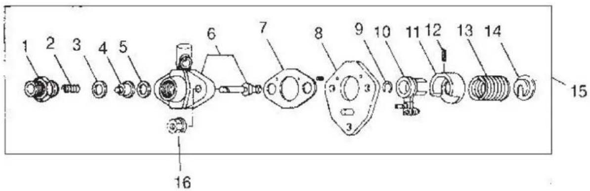
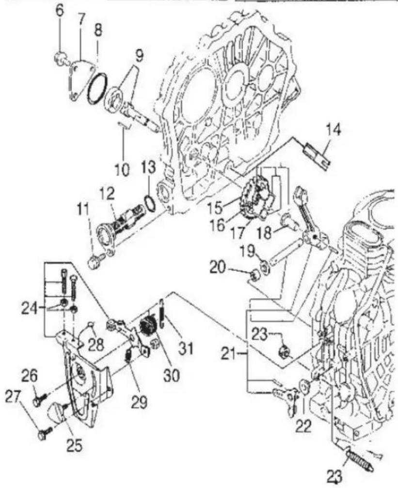
Fuel system
| Number | Name of part | Quantity |
| 1 | Bolt M8*45 (GB5787-86) | 1 |
| 2 | Fastened bolt for upper bracket of fuel tank | 1 |
| 3 | Flat washer 8 (GB97.1-85) | 1 |
| 4 | Upper bracket of fuel tank | 1 |
| 5 | Injector | 1 |
| 6 Fuel leak-off pipe connecting 2 | ||
| 7 | Fuel leak-off pipe | 1 |
| 8 | Shock absorbing pad of fuel tank | 4 |
| 9 | Fuel tank | 1 |
| 10 | Fuel pipe connecting | 2 |
| 11 | Fuel pipe | 1 |
| 12 | Gasket of fuel draining M6 (GB6177-86) | 1 |
| 13 | Cock of fuel draining (fuel pipe) | 1 |
| 14 | Lower bracket of fuel tank | 1 |
| 15 | Bolt M6*14 (GB5787-86) | 2 |
| 16 | Nut M6 (GB6177-86) | 2 |
| 17 | Flat washer 6 (GB97.1-85) | 1 |
| 18 | Fuel tank cock Assem | 1 |
| 19 | Flat washer | 1 |
| 20 | Clamp of fuel oil pipe | 2 |
| 21 | Fuel oil pipe | 1 |
| 22 | Gasket of fuel oil filter | 1 |
| 23 | Filter element Assem | 1 |
| 24 | Fuel injection pump | 1 |
| 25 | High pressure fuel pipe | 1 |
| 26 | Fuel oil filter | 1 |
| 27 | Fuel tank cap Assem | 1 |
| 28 | Cap of fuel injector | 1 |
Note: The fuel tank assembly includes: 9, 10, 11, 12, 13, 16, 17, 18, 19, 22, 23, 26, 27.
Lubricating and speed-control system
| Number | Name of part | Quantity |
| 1 | Bolt M6*12 (GB5787-86) | 2 |
| 2 | Oil filter cover | 1 |
| 3 | Oil filter cover gasket | 1 |
| 4 | Seal ring 20*2.65 | 1 |
| 5 | Oil filter assembly | 1 |
| 6 | Bolt M6*12 (GB5787-86) | 3 |
| 7 | Oil pump cover | 1 |
| 8 | O-ring 34.5*18 (GB3452.1-82) | 1 |
| 9 | Oil pump | 1 |
| 10 | Pin 3*16 (GB119-82) | 1 |
| 11 | Bolt M6*14 (GB5789-86) | 2 |
| 12 | Oil filter element | 1 |
| 13 | Seal ring 20*2.65 | 1 |
| 14 | Oil guide | 1 |
| 15 | Driving gear of oil pump | 1 |
| 16 | Pin of fly block | 1 |
| 17 | Fly block | 2 |
| 18 | Tappet of governor fork | 2 |
| 19 | Gasket of lever shaft | 1 |
| 20 | Bearing 7941/8 (GB290-64) | 1 |
| 21 | Fork lever assembly | 1 |
| 22 | Washer | 1 |
| 23 | Parts of fuel controller | 1 |
| 24 | Handle bracket | 1 |
| 25 | Speed-control lever | 1 |
| 26 | Bolt M6*14 (GB5787-86) | 2 |
| 27 | Bolt M6*18 (GB5787-86) | 1 |
| 28 | Lead seal | 1 |
| 29 | Return spring II | 1 |
| 30 | Return spring I | 1 |
| 31 | Speed-control spring | 1 |
| 32 | Bolt M6*45 (GB6172-86) | 1 |
| 33 | Nut M10*1.25 | 1 |
| 34 | FG parts of lever | 1 |
| 35 | FG governor spring | 1 |
| 36 | Bolt M6*14 (GB5789-86) | 1 |
| 37 | Nut M6 (GB39-88) | 1 |
| 38 | Washer | 2 |
| 39 | Handle shaft | 1 |


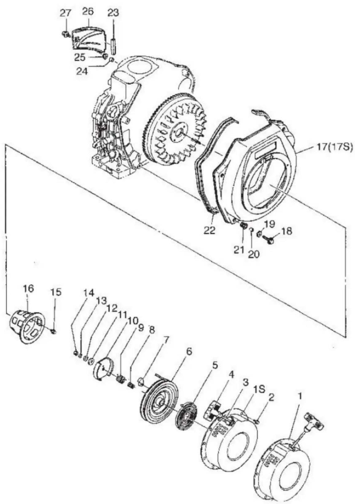
Cooling and recoil starter
| Number | Name of part | Quantity |
| 1 | Case Assem | 1 |
| 1S | 178FS case Assem | 1 |
| 2 | Bolt M6*8 (GB5787-86) | 4 |
| 3 | Starting rope | 1 |
| 4 | Starting handle | 1 |
| 5 | Flat spiral spring | 1 |
| 6 | Reel | 1 |
| 7 | Starting claw | 2 |
| 8 | Compressed spring | 1 |
| 9 | Torque spring | 1 |
| 10 | Plate of starting claw | 1 |
| 11 | Friction plate | 1 |
| 12 | Gasket of friction plate | 1 |
| 13 | Spring washer | 1 |
| 14 | Nut M6 (GB6170-86) | 1 |
| 15 | Bolt M6*12 (GB5789-86) | 3 or 4 |
| 16 | Starter | 1 |
| 17 | Wind leading case welded | 1 |
| 17S | 78FWind leading case welded Assem | 1 |
| 18 | Bolt M6*22 (GB5787-86) | 4 |
| 19 | Washer 6 (GB90-85) | 4 |
| 20 | Collar | 4 |
| 21 | Shock absorber | 4 |
| 22 | Pieces of shock pads | 1 |
| 23 | Shock isolation piece of wind leading plate | 1 |
| 24 | Collar | 1 |
| 25 | Pad | 1 |
| 26 | Wind leading plate | 1 |
| 27 | Bolt M6*22 (shaped piece) | 1 |
Note: Recoil starter kit parts.
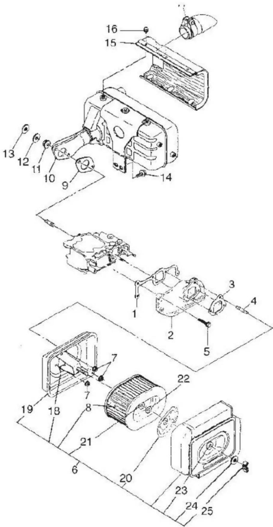
Air cleaner and silencer system
| Number | Name of part | Quantity |
| 1 | Gasket of intake pipe | 2 |
| 2 | Intake pipe | 1 |
| 3 | Gasket of air cleaner | 3 |
| 4 | Bolt | 1 |
| 5 | Shaped bolt M6*22 (GB5789-86) | 1 |
| 6 | Air filter assembly | 1 |
| 7 | Nut M6 (GB6177-86) | 1 |
| 8 | Air filter element | 1 |
| 9 | Gasket of muffler | 1 |
| 10 | Muffler assembly | 1 |
| 11 | Flat washer ∅8 | 2 |
| 12 | Spring washer ∅8 | 2 |
| 13 | Nut M8 (GB6170-86) | 1 |
| 14 | Bolt M6*14 (GB5789-86) | 2 |
| 15 | Screen cover of muffler | 1 |
| 16 | Bolt M6*14 (GB5789-86) | 1 |
| 17 | Connector | 1 |
| 18 | Sealing ring II of shock proof | 1 |
| 19 | Air cleaner Bottom Case Assem | 1 |
| 20 | Sealing ring I of shock proof | 1 |
| 21 | Shock absorber of air filter | 1 |
| 22 | Collar (GB6177-86) | 1 |
| 23 | Shock absorber of air filter (square) | 1 |
| 24 | Washer | 1 |
| 25 | Butterfly nut M8 | 1 |

- Delivery holder
- Delivery spring
- Delivery gasket
- Delivery valve
- Plunger
- Adjusting gasket
- Connecting plate of pump body
- Circlip
- Control lever Assem
- Spring seat I
- Pin of sleeve
- Fuel injecting pump
- Fuel injection pump spring
- Fuel pump assembly
- Nut M6
CHAPTER 5: Malfunction and remedy of diesel engine
Cause and remedy for the engine not being started
| CAUSE | REMEDY |
| The weather is cold, machine oil becomes more adhesive | Fill machine oil into crankshaft case after preheated. Fill machine oil into the inlet manifold. Disassemble the connection belt of matching machine and then start the diesel engine. Stop the engine when the engine becomes hot and reassemble the belt. Start the engine again. |
| Malfunction of fuel system. The fuel is mixed with water | Clean fuel tank filter and fuel pipe, change fuel. |
| The fuel becomes thickened and is not easy to flow | Use the specific fuel. |
| There is air in the fuel system | Drain out the air and tighten each connector of fuel pipe. |
| Injection fuel is little or no, the spray is not good | Check the position of speed governor handle, clean spray nozzle, fuel pump, maintain or change the pump or nozzle if necessary. |
| Combustion is not complete | The spray nozzle is not good, delivery angle is not correct, gasket of cylinder head is leaky and the pressure of compression is not enough. Remedy with its cause. |
| Diesel fuel delivery is interrupted | Diesel fuel is too little in the fuel tank. Fill the fuel into the fuel tank. If the fuel pipe and fuel filter are obstructed or leaky, remedy them. |
| Compression pressure is not enough in the cylinder, the nut of cylinder head is not tightened or gasket of cylinder is damaged or leaky. | Tighten the nut of cylinder head, according to diagonal line sequence and standard requirement, check gasket of cylinder head once again after pre-running the diesel engine. |
| The gap of piston ring is too big because of water | Change the piston ring. |
| Each gap of piston rings lines up and causes leakage | Set each gap of piston at an angle of 120°. |
| The piston rings are stuck seriously or broken | Clean with diesel fuel or change rings. |
| Gas valves leakage | Grind the gas valves, if the vestige is too deep, please send it to factory for remedy. |
| The valve clearance is not correct | Adjust the clearance as specified. |
| The valve stem is clipped on guide pipe | Disassemble the gas valve and clean the stem and guide pipe. |
Cause and remedy for not enough power of diesel engine
| CAUSE | REMEDY |
| Malfunction of fuel system: parts obstruction of fuel pipeline and fuel filter | Check fuel switch, it must be opened fully. Clean fuel filter and fuel pipeline. |
| The pumping of fuel is not good | Maintain or change the damaged parts of fuel pump. |
| Malfunction of nozzle: injection pressure is not correct | Adjust the injection pressure. |
| Spray hole carbon deposit | Clean. |
| Needle valve adhered | Clean or change. |
| Fitting is too loose between needle valve and needle valve body | Change. |
| Air filter is obstructed | Disassemble to clean or change the core of filter. |
| Speed is not high enough | Check the speed of diesel engine with tachometer. Adjust the high-speed limit screw. |
Cause and remedy for the engine stopping automatically
| CAUSE | REMEDY |
| Malfunction of fuel system: No fuel | Add fuel. |
| Fuel pipeline or filter is obstructed | Maintain or clean. |
| There is air in the fuel system | Drain out the air. |
| Needle valve of nozzle adhered | Clean, grind the nozzle or change it if necessary. |
| Air filter is obstructed | Maintain or brush off. |
| The load increases suddenly | Decrease the load. |
Cause and remedy for exhaust with black smoke
| CAUSE | REMEDY |
| Overload | Decrease the load, if the working machine is not properly matched, change it. |
| Fuel injection is not good | Check the injection pressure and spray condition and correct it. Or change the nozzle if it is damaged. |
| Air is not enough or leaky | Clean the air filter, check the cause of leakage and remedy. |
Cause and remedy for exhaust with blue smoke
| CAUSE | REMEDY |
| There is machine oil in the cylinder | Check oil level, drain away the unnecessary machine oil. |
| Piston ring is clipped or worn, and its springiness is not enough, or each gap of ring turns to the same direction to make the machine oil go up | Check, change the piston ring, and cross each gap position. |
| The gap is too big between piston and cylinder | Remedy or change. |
| Valve and guide are worn | Change. |
Cause and remedy for exhaust with white smoke
| CAUSE | REMEDY |
| There is water in diesel fuel | Clean the fuel tank and diesel filter, change diesel fuel. |
Methods and positions of stopping to check when the engine is malfunctioning
| CAUSE | REMEDY |
| Speed is sometimes high, sometimes low | Check the speed governor system whether it is nimble. Check whether there is air in the fuel pipeline. |
| Abnormal sound suddenly appears | Check each motional part carefully. |
| Exhaust with black smoke suddenly | Check fuel system, especially nozzle. |
| There is a metal knocking sound rhythmically in the cylinder | The fuel delivery angle is too big. Adjust it. |

natural_image
Orange and black industrial engine pump with visible brand mark '188FA' (no text or symbols on the device body)Wstęp
natural_image
Technical line drawing of a mechanical assembly (no text or symbols visible)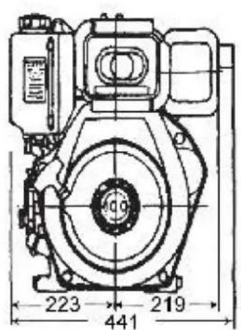

Instalacja
natural_image
Technical line drawing of a mechanical device with no visible text or symbolsRys. 1-1

natural_image
Technical line drawing of a mechanical assembly with no visible text or symbolsnatural_image
Technical line drawing of a mechanical assembly with no visible text or symbolsnatural_image
Mechanical diagram showing a lever mechanism with motion arrows (no text or symbols)natural_image
Mechanical component with three directional arrows indicating force or movement (no visible text or symbols)natural_image
Line drawing of three types of electrical connectors or components (no text or symbols)
Układ paliwowy


natural_image
Orange 188FA diesel engine pump with visible branding and control buttons (no text-heavy elements)Zavedení
natural_image
Technical line drawing of a mechanical assembly (no text or symbols visible)
natural_image
Technical line drawing of a mechanical device with no visible text or symbolsObr. 1-1

natural_image
Technical line drawing of a mechanical assembly with no visible text or symbolsnatural_image
Technical line drawing of a mechanical assembly with no visible text or symbolsnatural_image
Line drawing of a mechanical device with motion arrows indicating movement (no text or symbols)natural_image
Mechanical component diagram with directional arrows indicating force or movement (no text or symbols)natural_image
Line drawing of three types of electrical connectors or sensors, no text or symbols present
natural_image
Industrial machine component with visible fan and motor (no text or symbols)Palivový systém


natural_image
Orange 188FA diesel engine pump with black control panel and visible branding (no text or symbols on the device body)Introduction
natural_image
Technical line drawing of a mechanical assembly (no text or symbols visible)

Installation
natural_image
Technical line drawing of a mechanical device with no visible text or symbolsFig 1-1

natural_image
Technical line drawing of a mechanical assembly with no visible text or symbolsnatural_image
Technical line drawing of a mechanical assembly with no visible text or symbolsnatural_image
Line drawing of a mechanical device with motion arrows indicating movement (no text or symbols)natural_image
Pure technical line drawing of a mechanical component without any text, numbers, or symbolsnatural_image
Pure mechanical diagram showing a lever mechanism with arrows indicating direction (no text or symbols)natural_image
Mechanical component diagram with directional arrows indicating force or movement (no text or symbols)natural_image
Technical line drawing of a mechanical device with two connectors and a bulb (no text or symbols)


natural_image
Orange 188FA diesel engine pump with black control panel and visible branding (no text or symbols on the device body)Introduzione
natural_image
Technical line drawing of a mechanical assembly (no text or symbols visible)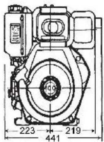
natural_image
Technical line drawing of a mechanical device with no visible text or symbolsFigura 1-1

bar
SAE | Temperature Range (°C) | 0 | 20 | 40 | 60 | 80 | 100 | |---|---|---|---|---|---|---| | -30 | -20 | -10 | 0 | 10 | 20 | 30 | | -20 | -10 | 0 | 10 | 20 | 30 | 40 | | -10 | 0 | 10 | 20 | 30 | 40 | 50 | | 0 | 10 | 20 | 30 | 40 | 50 | 60 | | 10 | 20 | 30 | 40 | 50 | 60 | 70 | | 20 | 30 | 40 | 50 | 60 | 70 | 80 | | 30 | 40 | 50 | 60 | 70 | 80 | 90 | | 40 | 50 | 60 | 70 | 80 | 90 | 100 | The chart displays a grid of horizontal bars representing temperature ranges in °C for each temperature level. The legend indicates 'W' (Width) and 'T' (Depth). The x-axis is labeled 'Temperature (°C)' with a scale from -30 to 40. The y-axis is labeled 'SAE'. The bars are stacked to show the distribution of each temperature level within the grid. No explicit numerical values or units are provided for the bars.natural_image
Mechanical assembly diagram showing a lever mechanism with no visible text or symbolsnatural_image
Technical line drawing of a mechanical assembly with no visible text or symbolsnatural_image
Line drawing of a mechanical device with motion arrows indicating rotation (no text or symbols)natural_image
Pure technical line drawing of a mechanical bracket or support structure without any text, numbers, or symbolsnatural_image
Pure mechanical diagram showing a lever mechanism with arrows indicating direction (no text or symbols)natural_image
Mechanical component diagram with directional arrows indicating force or movement (no text or symbols)natural_image
Technical line drawing of a mechanical device with two connectors and a cable (no text or symbols)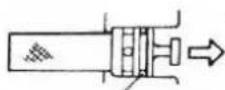
natural_image
Industrial machine component with visible fan and motor (no text or symbols)Nota: il gruppo serbatoio carburante include: 9, 10, 11, 12, 13, 16, 17, 18, 19, 22, 23, 26, 27.