PG-101 - Generator MSW - Free user manual and instructions
Find the device manual for free PG-101 MSW in PDF.

User questions about PG-101 MSW
0 question about this device. Answer the ones you know or ask your own.
Ask a new question about this device
Download the instructions for your Generator in PDF format for free! Find your manual PG-101 - MSW and take your electronic device back in hand. On this page are published all the documents necessary for the use of your device. PG-101 by MSW.
USER MANUAL PG-101 MSW
natural_image
Close-up of a hand adjusting a mechanical component with a tool (no visible text or symbols)natural_image
Close-up of a hand inserting a plug into a mechanical component (no visible text or symbols)
natural_image
Close-up of a mechanical device with warning symbols and circular arrows indicating cycle (no readable text or labels)natural_image
Close-up of a mechanical assembly under a structural beam, showing no visible text or symbolsnatural_image
Close-up of a black industrial machine with directional arrows indicating rotation or cycle (no text or symbols visible)natural_image
Close-up of a black automotive engine component with visible exhaust pipe and circular emblem (no text or symbols)natural_image
Close-up of a mechanical device with circular components and warning symbols, no readable text or labels present.4) Steuerfeld
Betriebsanzeige-LED
natural_image
Close-up of a mechanical assembly with visible components and no readable text or symbolsnatural_image
Close-up of a black industrial machine component with visible hydraulic heads and mounting brackets (no text or symbols)This User Manual has been translated for your convenience using machine translation. Reasonable efforts have been made to provide an accurate translation; however, no automated translation is perfect nor is it intended to replace human translators. The official User Manual is the English version. Any discrepancies or differences created in the translation are not binding and have no legal effect for compliance or enforcement purposes. If any questions arise related to the accuracy of the information contained in the User Manual, please refer to the English version of those contents which is the official version.
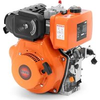
Technical data
| Parameter description | Parameter value | |||
| Product name | Inverter generator | |||
| Model | MSW-PG-100 | MSW-PG-101 | MSW-PG-102 | MSW-PG-103 |
| Power [W] | 3600 | 4200 | 3600 | 3600 |
| Maximum power [W] | 3500 | 3800 | 3200 | 2500 |
| Rated power 50 Hz [kVA] | 4 | 4.4 | 3.8 | 2.8 |
| Power factor | 1 | 1 | 1 | 1 |
| Fuel type | petrol | petrol | petrol | petrol |
| Type of engine oil | 15W40 | 15W40 | 15W40 | 15W40 |
| Fuel tank capacity [l] | 5 | 5 | 5 | 5 |
| Oil tank capacity [l] | 0.6 | 0.6 | 0.6 | 0.6 |
| Displacement [cm3] | 196 | 212 | 196 | 196 |
| Fuel consumption [g/kWh] | 395 | 374 | 395 | 395 |
| Cylinder diameter x stroke [mm] | 68x54 | 70x55 | 68x54 | 68x54 |
| Start | Manual | Manual | Manual | Manual |
| AC voltage [V]/ Frequency [Hz] | 230/50 | 230/50 | 230/50 | 230/50 |
| Total harmonic distortion [%] | <5 | <5 | <5 | <5 |
| Rated output power [W] | 60 | 60 | 60 | 60 |
| Rated output current [A] | 5 | 5 | 5 | 5 |
| Sound power level [db] | 97 | 97 | 96 | 96 |
| Sound pressure level [db] | 95 | 97 | 95 | 95 |
| Maximum ambient temperature during operation [°C] | 40 | 40 | 40 | 40 |
| Dimensions [cm] | 48x33x47.5 | 47x32x48 | 47x33x48 | 47x33x47 |
| Weight [kg] | 26.2 | 26.8 | 26 | 25 |
1. General description
The user manual is designed to assist in the safe and trouble-free use of the device. The product is designed and manufactured in accordance with strict technical guidelines, using state-of-the-art technologies and components. Additionally, it is produced in compliance with the most stringent quality standards.
DO NOT USE THE DEVICE UNLESS YOU HAVE THOROUGHLY READ AND UNDERSTOOD THIS USER MANUAL.
To increase the product life of the device and to ensure trouble-free operation, use it in accordance with this user manual and regularly perform maintenance tasks. The technical data and specifications in this user manual are up to date. The manufacturer reserves the right to make changes associated with quality improvement. The device is designed to reduce noise emission risks to a minimum, taking into account technological progress and noise reduction opportunities.
Legend
 | The product satisfies the relevant safety standards. | |
 | Read instructions before use. | |
 | The product must be recycled. | |
 | WARNING! or CAUTION! or REMEMBER! Applicable to the given situation.(general warning sign) | |
 | Use ear protection. Exposure to loud noise may result in hearing loss. | |
 | Wear protective gloves. | |
 | ATTENTION! Electric shock warning! | |
 | ATTENTION! Fire hazard - flammable materials! | |
 | WARNING! Toxic substances, danger of poisoning! | |
 | ATTENTION! Hot surface, risk of burns! | |
 | Do not smoke near the device. The device contains flammable substances. | |

PLEASE NOTE! Drawings in this manual are for illustration purposes only and in some details may differ from the actual product.
2. Usage safety

ATTENTION!
Read all safety warnings and all instructions. Failure to follow the warnings and instructions may result in electric shock, fire and/or serious injury or even death.
The terms "device" or "product" are used in the warnings and instructions to refer to:
Inverter generator
2.1. Electrical safety
a) Avoid touching earthed elements such as pipes, heaters, boilers and refrigerators. There is an increased risk of electric shock if the earthed device is exposed to rain, comes into direct contact with a wet surface or is operating in a damp environment. Water getting into the device increases the risk of damage to the device and of electric shock.
b) Do not touch the device with wet or damp hands.
c) ATTENTION! DANGER TO LIFE! While cleaning, never immerse the device in water or other liquids.
d) The generating set shall not be connected to other power sources, such as the power company supply mains.
2.2. Engine operation safety
a) Do not smoke near the device. The device contains flammable substances.
b) W The engine gets very hot during operation. Do not touch the hot engine because it may cause urns.
c) Add oil till the full marking before start using the device.
d) Oil leaking from the machine should be reported to the appropriate services or comply with legal requirements applicable in the area of use.
e) Danger! Danger to health and the risk of explosion of the internal combustion engine
f) Poisonous carbon monoxide is present in the engine exhaust. Remaining in a carbon monoxide environment may lead to losing consciousness or even death.
g) Protect the engine from heat, sparks and flame. Do not smoke in the vicinity of the chipper!
h) Before refuelling the engine should be turned off and cooled down
i) Warning! Risk of engine damage due to wrong fuel.
j) Make sure that all users have read, understood and follow the manual.
k) Misuse or careless use of the device may cause serious injuries.
I) Before each cleaning, regulation, accessory change, or if the device is not in use, turn the engine off and completely cool the device.
m) Do not touch moving parts or accessories unless the engine is turned off and left to cool.
n) Stay away from moving and rotating parts as they may cause injury.
o) Do not use the machine if all protective covers are not installed.
p) Do not touch the silencer or other hot elements when the engine is hot it may cause serious burns.
q) Make sure that fuel is stored only in certified containers (e.g. canister).
r) Do not refuel near sparks, flames or lit cigarettes.
s) Stop the engine before refuelling. Never refuel while the engine is running or is still hot. Otherwise, spilled or evaporated fuel may catch fire from engine sparks or silencer heat.
t) Do not overfill fuel tank and avoid spilling fuel while refuelling. Spilled fuel or fuel fumes may catch fire. If fuel has been spilled, make sure that the area is dry before starting the engine.
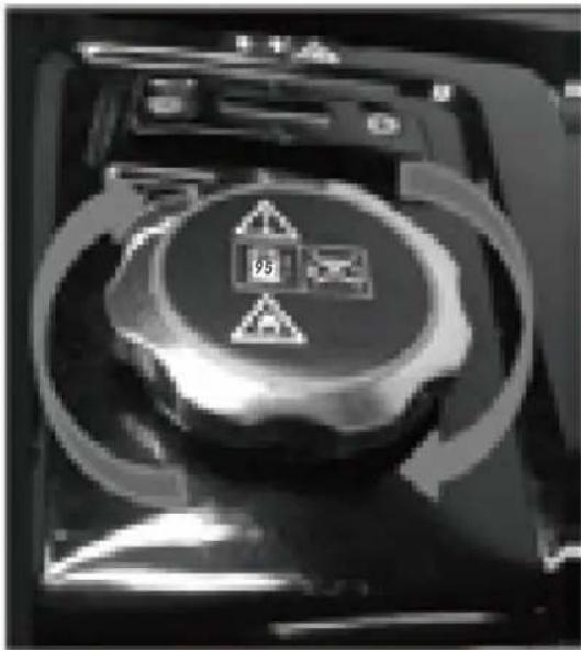
u) After refuelling, make sure that the fuel tank cap is properly screwed on.
v) Do not operate the engine or refuel in enclosed areas without appropriate ventilation.
w) Avoid operating the machine in enclosed spaces, tunnels or other poorly ventilated places as the exhaust fumes contain lethal/harmful fumes and gases. If operating the machine in such conditions is unavoidable, provide adequate exhaust extraction.
x) To transport: Stop the engine. Close and secure the fuel tank cap. Switch the fuel valve to the "OFF-O" position. Drain the fuel tank before long-distance transportation or on bumpy roads.
y) Keep flammable materials (petrol, matches, straw, etc.) away from the exhaust.
2.3. Safety in the workplace
a) Make sure the workplace is clean and well lit. A messy or poorly lit workplace may lead to accidents. Try to think ahead, observe what is going on and use common sense when working with the device.
b) Do not use the device in a potentially explosive environment, for example in the presence of flammable liquids, gases or dust. The device generates sparks which may ignite dust or fumes.
c) If you discover damage or irregular operation, immediately switch the device off and report it to a supervisor without delay.
d) Only the manufacturer's service point may repair the device. Do not attempt any repairs independently!
e) In case of fire, use a powder or carbon dioxide (CO2) fire extinguisher (one intended for use on live electrical devices) to put it out.
f) Use the device in a well-ventilated space.
g) Regularly inspect the condition of the safety labels. If the labels are illegible, they must be replaced.
h) Please keep this manual available for future reference. If this device is passed on to a third party, the manual must be passed on with it.
i) Keep packaging elements and small assembly parts in a place not available to children.
j) Keep the device away from children and animals.
k) If this device is used together with another equipment, the remaining instructions for use shall also be followed.
2.4. Personal safety
a) Do not use the device when tired, ill or under the influence of alcohol, narcotics or medication which can significantly impair the ability to operate the device.
b) The machine may be operated by physically fit persons who are able to handle the machine, are properly trained, who have reviewed this operating manual and have received training in occupational health and safety.
c) The machine is not designed to be handled by persons (including children) with limited mental and sensory functions or persons lacking relevant experience and/or knowledge unless they are supervised by a person responsible for their safety or they have received instruction on how to operate the machine.
d) When working with the device, use common sense and stay alert. Temporary loss of concentration while using the device may lead to serious injuries.
e) Use personal protective equipment as required for working with the device, specified in section 1 (Legend). The use of correct and approved personal protective equipment reduces the risk of injury.
f) The device is not a toy. Children must be supervised to ensure that they do not play with the device.
2.5. Personal safety
a) Do not overload the device. Use the appropriate tools for the given task. A correctly-selected device will perform the task for which it was designed better and in a safer manner.
b) When not in use, store in a safe place, away from children and people not familiar with the device who have not read the user manual. The device may pose a hazard in the hands of inexperienced users.
c) Keep the device in perfect technical condition. Before each use check for general damage and especially check for cracked parts or elements and for any other conditions which may impact the safe operation of the device. If damage is discovered, hand over the device for repair before use.
d) Keep the device out of the reach of children.
e) Device repair or maintenance should be carried out by qualified persons, only using original spare parts. This will ensure safe use.
f) To ensure the operational integrity of the device, do not remove factory-fitted guards and do not loosen any screws.
g) When transporting and handling the device between the warehouse and the destination, observe the occupational health and safety principles for manual transport operations which apply in the country where the device will be used.
h) Do not move, adjust or rotate the device in the course of work.
i) Do not leave this appliance unattended while it is in use.
j) Clean the device regularly to prevent stubborn grime from accumulating.
k) It is forbidden to interfere with the structure of the device in order to change its parameters or construction.
I) Keep the device away from sources of fire and heat.

ATTENTION! Despite the safe design of the device and its protective features, and despite the use of additional elements protecting the operator, there is still a slight risk of accident or injury when using the device. Stay alert and use common sense when using the device.
3. Use guidelines
The machine is used for independent generation of electrical energy and for powering other devices. The user is liable for any damage resulting from unintended use of the device.
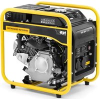
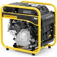
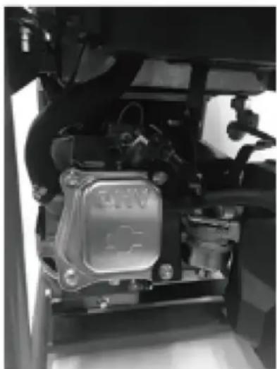
3.1. Device description
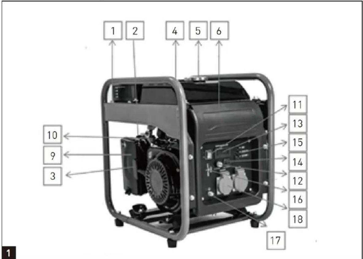
1 - Frame
2 - Choke
3 - Recoil Starter
4 - Fuel Gauge
5 - Fuel Tank Cap
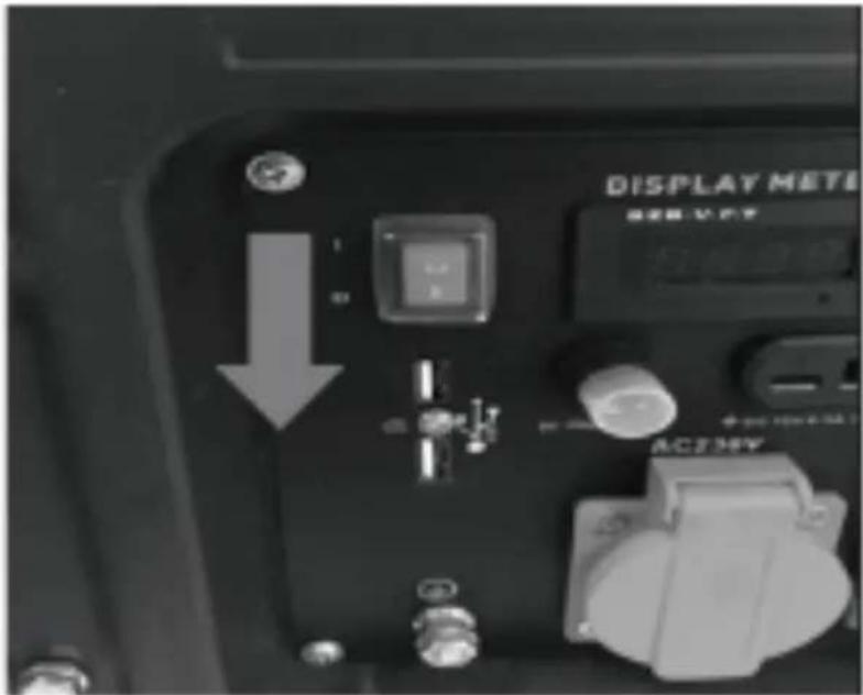
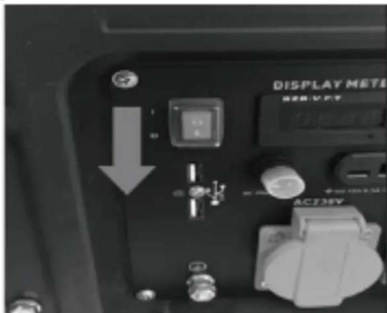
6 - Control Panel
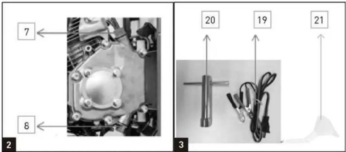
7 - Oil Dipstick
8 - Oil Fill Port
9 - Air Filter
10 - Fuel Tap
11 - Engine ON/OFF Switch
12 - DC overload protector - Reset
13 - Display
14 - 12V DC Outlet
15 - LED status indicator
16 - 5V USB Outlet
17 - Ground terminal
18 - AC Socket
19 - 12V DC Cable
20 - Spark Plug Wrench
21 - Funnel
3.2. Pre-operation check
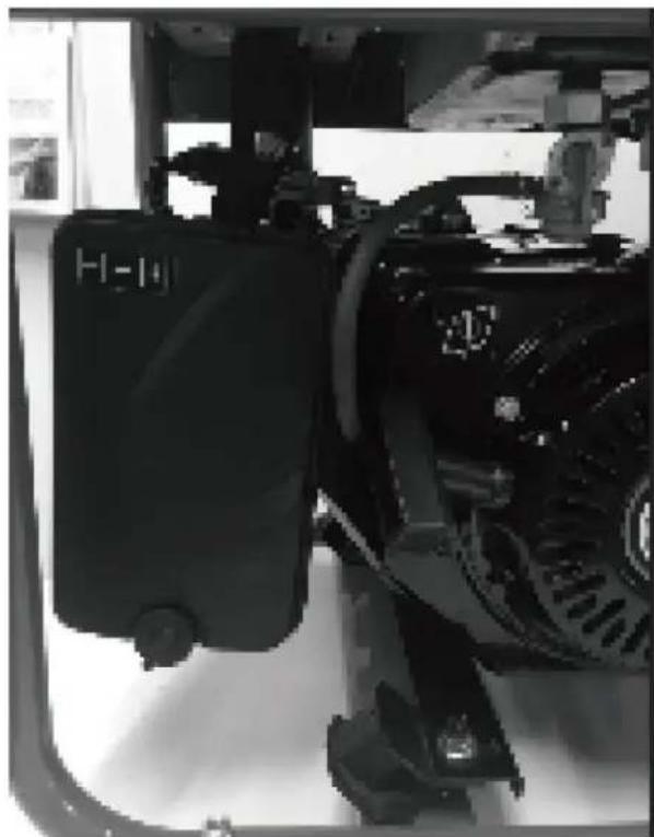
1) Filling the Engine Oil
SAE 10W-30 is recommended for general, all temperature use. Other viscosities shown in the chart may be used when the average temperature in your area is within the indicated range.

line
| Position | Value | |---|---| | 5W-30 | -20 | | 10W-30 | -10 | | SAE 30 | 40 |a) Remove the oil dipstick (7) and wipe the dipstick clean.
b) Check the oil level by inserting the dipstick into the filler neck without screwing it in,
natural_image
Close-up of a hand adjusting a mechanical component with a tool (no visible text or symbols)c) Check the oil level. The oil level must between "H" and "L". If near the lower level, fill to upper level.
natural_image
Close-up of a hand holding a small cylindrical object, possibly a mechanical component or tool, with no visible text or symbols.
d) Tighten the oil dipstick (7).

CAUTION! Carefully pour in engine oil Avoid spilling!
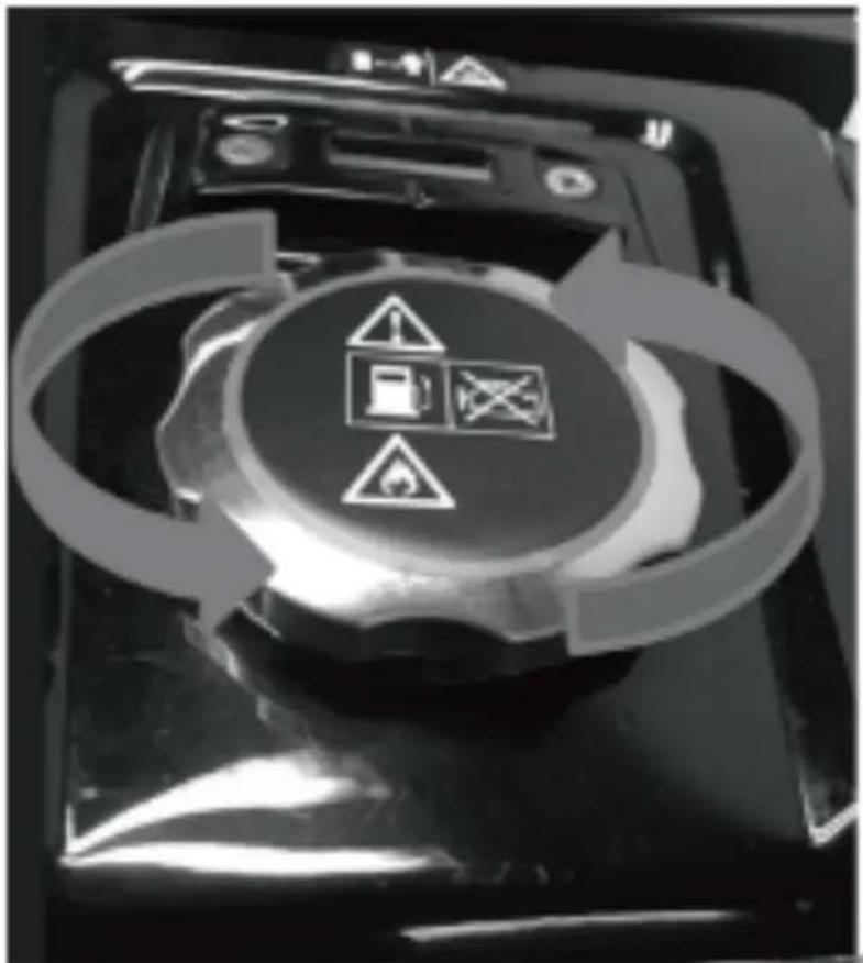
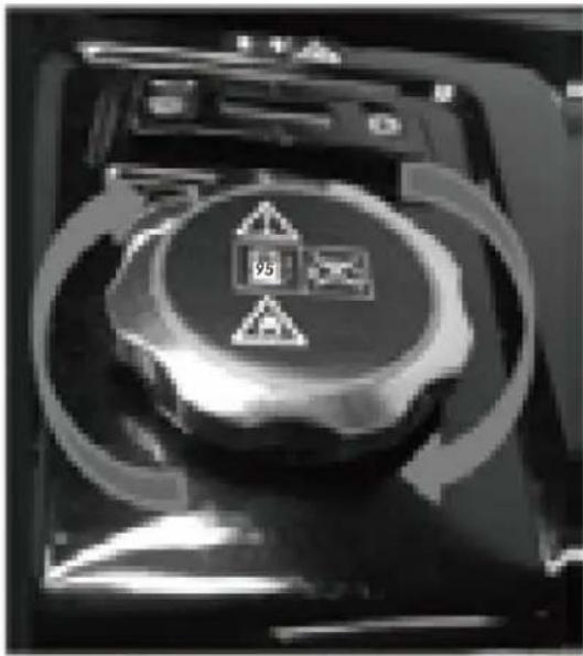
2) Filling the fuel
You must fill the fuel before start the engine.
- Open the fuel tank cap.
natural_image
Close-up of a mechanical device with warning symbols and circular arrows indicating cycle (no readable text)- Fill in fuel to the fuel tank, do not higher than the warning line of the fuel tank.
- Close the fuel tank cap.
3) Environmental protection
- Dispose of soiled maintenance material and operating materials at the appropriate collection point.
• Recycle packaging material, metal and plastics.
4) Ground connection
The housing is allowed to be connected to earth in order to discharge static electricity.
To do this, connect one end of a cable to the earth terminal (17) on the generator and the other end to an external earth (for example an earthling rod).
3.3. Device use
NOTE: The generator has been shipped without engine oil. Fill with oil, otherwise the device will not start.
1) Start the engine
NOTE: Do not connect the electric load or equipment before starting the engine.
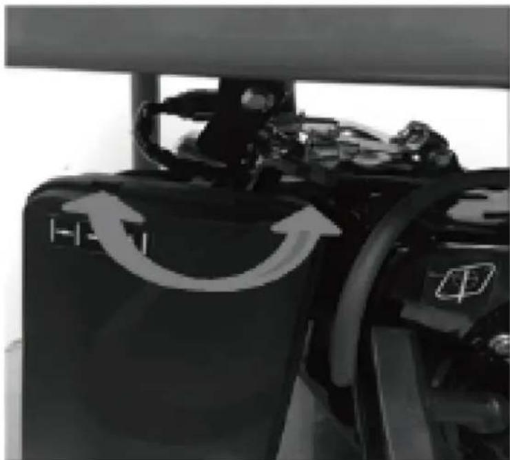
- Open the fuel tap (10) by turning it down.

natural_image
Close-up of a mechanical assembly under a structural beam, showing no visible text or symbols- Move the engine ON/OFF switch (11) to position "I".

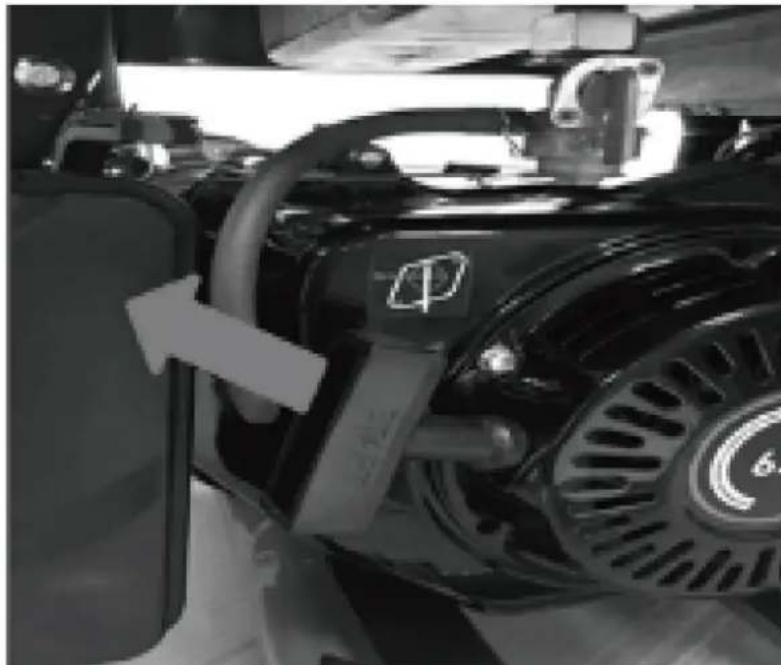
- Move the choke (2) to position I∅I (if the engine has warmed up, then ignore this step).
natural_image
Close-up of a black industrial machine with directional arrows indicating rotation or cycle (no text or symbols visible)- Start the engine with the grip of recoil starter (3) by pulling the handle forcefully. If the engine does not start, pull the handle again.
natural_image
Close-up of a black industrial engine component with visible exhaust pipe and valve (no text or symbols)- Push the choke (2) back again after the engine has started.
IMPORTANT!
When starting with the pull cord, the motor may recoil suddenly as it starts up, resulting in hand injuries. Wear protective gloves when starting the equipment.

WARNING: Once the generator has started, release the starting handle slowly to avoid injury/damage as it whips back.
2) Connecting Electric Devices
AC mode
a) Ensure that electrical equipment is switched off before connecting to the generator.
b) Connect the plug of the electrical equipment into the appropriate socket.
c) The generator can supply 230 V AC.
12V DC mode
a) Set DC overload protector- Reset (12) to "ON"
b) Connect the DC cable to the DC output.
c) Clamp the red wire to the positive (+) terminal and the black wire to the negative (-) terminal of the equipment you would like to use.
d) If the DC overload protector activates, wait for a few minutes and then press the DC breaker shown on right.
USB application
The USB socket (16) should only be used for charging 5VDC Max. 2A mobile or digital equipment.

CAUTION!
- Be sure the total load is within generator rated output.
- Make sure that the appliance being connected is in good working order, if it begins to act abnormally or stops suddenly, disconnect it from the generator.
- Any device with contains an inductive load e.g. devices that contain a motor may require more current on startup.
3) Shutting Down the Generator
- Disconnect all appliances connected to the generator.
- Set the Engine ON/OFF Switch (11) to position "0".
- Disconnect all appliances connected to the generator. - Set the Engine ON/OFF Switch (11) to position "0".
- Close the fuel tap (10)
natural_image
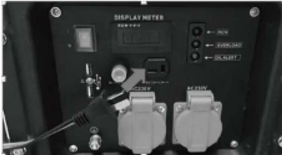
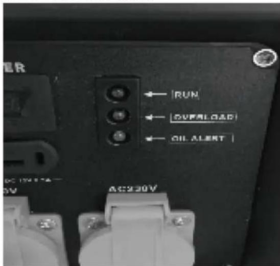
Close-up of a mechanical device with circular components and directional arrows indicating rotation (no readable text or symbols)4) Control panel
Run Indicator LED
- The power indicator LED (green) illuminates when power is available to outputs.
Overload Indicator LED
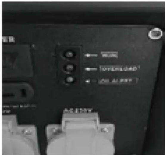
- If the generator is overloaded or if there is a short in the connected appliance the overload indicator LED (red) will go ON and current to the connected appliance will be shut off. The output indicator LED (green) will turn off. The power indicator LED (green) illuminates when power is available to outputs.
- Substantial overloading that continuously lights the overload indicator light (red) may damage the generator. Marginal overloading that temporarily lights the overload indicator LED (red) may shorten the service life of the generator. Stop the engine if the overload indicator light (red) switches ON and investigate the overload source.
Overload protection
If the overload switch has tripped and cuts off the power, be sure that all appliances are in good working order before connecting them to the generator. If an appliance begins to operate abnormally, becomes sluggish, or stops suddenly, turn "OFF" the generator.
1) Disconnect the appliance and push the engine switch into the off position.
2) Start the generator as described in "Starting the engine" section.
3) Refit the appliance, if the Overload trips again then the equipment / appliance needs to be checked.
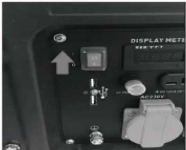
Low Oil Indicator LED

- The oil indicator is designed to prevent engine damage caused by an insufficient amount of oil in the crankcase.
- If the oil level becomes low while operating, the generator will automatically switch off to prevent damage.
• If the oil indicator LED (yellow) comes on add engine oil.
Overloading (Inrush Current)
You may find that even though the appliance you wish to connect to the generator is below the rated power, the generator overloads.
Some appliances require a higher power than noted on the appliance for start up; this is called inrush current. Some examples are listed below.
| Appliance | Running Wattage | Start-up Wattage |
| Light | 70 W | 70 W |
| Airless Sprayer | 650 W | 1300 W |
| Refrigerator | 700 W | 2000 W |
| Water Pump | 800 W | 2000 W |
| Air Compressor(1 HP) | 1100 W | 4000 W |
| Circular Saw | 1200 W | 2100 W |
| Heater | 2000 W | 2000 W |
| Mitre Saw | 2100 W | 3200 W |
| Electric Stove | 2400 W | 2400 W |
Table details are approximate. Always check your appliance for the accurate wattage.
3.4. Cleaning and maintenance
Maintenance
- Good maintenance is essential for safe, economical and trouble-free operation. It will also help reduce air pollution.
- The purpose of the maintenance and adjustment schedule is to keep the machine in the best operating condition.
- Turn off the engine before performing any maintenance. The exhaust contains poisonous carbon monoxide gas. Please always select recommended accessories. The accessories which have not equivalent quality may damage the machine.
- Please never use non-approved components and never remove the safety devices.

CAUTION!
- Always stop the engine before servicing, and disconnect all appliances to avoid receiving an electrical shock.
• Periodic checks and maintenance are very important for keeping the generator in good condition
| Item | Daily check | 20 Hrs month | 50 Hrs or every 3 months | 100 Hrs or every 6 months | 300 Hrs or every 1 year |
| Machine oil check | Check | ||||
| Replace engine oil | Replace | Replace | |||
| Air filter check | Check | ||||
| Air filter wash | Check | ||||
| Spark plug | Check | ||||
| Valve clearance | Check/ adjust | ||||
| Cylinder cover wash | Check | ||||
| Fuel tank wash | Wash if necessary, replace every 3 years | ||||
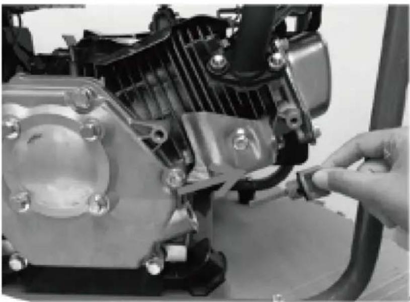
1) Spark Plug Servicing
Use only good quality spark plugs. To ensure proper engine operation, the spark plug must be properly gapped and free of deposits.
a) Pull out the spark plug lead.
b) Remove the spark plug using the spark plug wrench supplied by turning ant-clockwise.
natural_image
Close-up of a mechanical assembly with visible components and no readable text or symbolsc) Clean the electrode with a metal brush and remove any carbon build-up or replace the spark plug. Set the electrode gap to 0.6 - 0.7mm 0.6 - 0.7mm
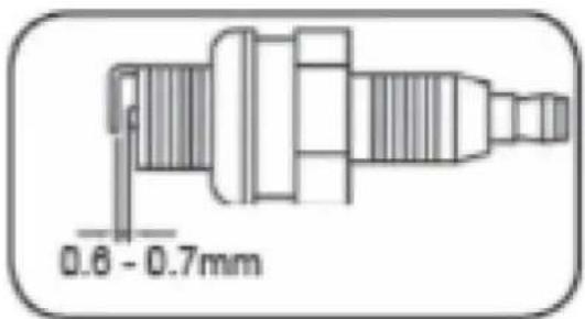
d) Install the spark plug carefully by hand, to avoid cross threading. Tighten it securely with Spark plug wrench.
e) Reinstall the spark plug lead.
2) Air Filter Service
CAUTION: Do not use the generator without the air filter fitted, this can damage the generator.
- Open clips and remove the air filter cover.
natural_image
Close-up of a mechanical device with a black housing and control panel (no visible text or symbols)- Remove the filter elements.
• Do not use abrasive cleaning agents or petrol to clean the elements.
- Clean the elements by tapping them on a flat surface. In cases of stubborn dirt first clean with soapy water, and then rinse with clear water and air dry.
- Assemble in reverse order.

WARNING: Do not use inflammable solvents or petrol to clean the filter.
3) Handling Fuels

CAUTION! Fuels are flammable and explosive. Avoid the risk of explosion and fire.
a) Switch off the motor and allow cooling down before refilling.
b) Smoking and any other naked flame is forbidden when handling fuels.
c) Only store and mix fuels in authorized and clearly labeled canisters.
d) Keep fuels under lock and key. Fuels may vaporize even at ambient temperature and may collect at floor level in closed rooms (risk of explosion).
e) Start the appliance at least nine meters away from the place you tanked it.

CAUTION! Fuels are poisonous! They contain substances that are immediately poisonous and which are capable of causing damage over time. Observe the care measures in order to prevent the substances entering the body.
a) Only refill the device or transfer fuel from one canister to another out in the open or in a well-ventilated space.
b) Do not breathe in the fuel vapors.
c) Avoid contact with skin and eyes.
d) When transferring fuel, use gloves.

CAUTION: If used incorrectly, fuels may damage the environment.
a) Refuel carefully. Fuel may not enter the soil or the sewer system.
b) Remaining fuels must be disposed of correctly. Never dispose with the house waste.
c) Fuels may only be stored for a short time. Only purchase quantities that will be used within a few months.
Cleaning
Avoid using solvents when cleaning plastic parts. Most plastic parts are susceptible to damage from various types of commercial solvents and may be damaged by their use. Use clean cloths to remove dirt, carbon dust, etc.
Storing and transportation
Store the machine, operating instructions and where necessary the accessories in the original packaging. In this way you will always have all the information and parts ready to hand. Pack the device well or use the original packaging in order to avoid transit damage. Always keep the machine in dry place.
1) Storage
Before any storage or transportation:
a) Switch the motor off.
b) Allow the generator to cool down.
c) Pull out the spare plug connector.

CAUTION: The generator must be stored at a frost-protected location.
- Allow the generator to cool down and empty the tank.
- Store the generator in a dry and well-ventilated place.
EN
- Store the generator horizontally.
- Clean the generator completely by wiping the generator with a damp cloth.
2) Transportation
a) Allow the generator to cool down.
b) Empty the tank.
c) Transport the machine horizontally.
d) Secure the machine from shifting and tipping.
Changing the engine oil
CAUTION: prolonged exposure to used engine oil is dangerous; always wash your hands thoroughly after handling used engine oil.
1) Place a oil collection tray under the drain plug.
2) Unscrew the drain plug, and allow the used engine oil to drain from the crankcase into the oil collection tray.
NOTE: Drain the engine oil when the engine is warm, this will ensure the oil flows out quicker.
3) Fill the crankcase with engine oil to the 'H' mark on the dipstick.
4) Screw the drain plug.
Disposal and recycling
The unit is supplied in packaging to prevent its being damaged in transit. This packaging is raw material and can therefore be reused or can be returned to the raw material system.
The unit and its accessories are made of various types of material, such as metal and plastic.
Defective components must be disposed of as special waste. Ask your dealer or your local council.
One of the most damaging sources of pollution is oil; Do not throw away used engine oil in with your domestic trash or down drains and sinks. Place it in a leak proof container and take it to your local waste disposal site
Trouble shooting
Before performing any maintenance or cleaning work, always turn off the engine and wait until the generator has come to a standstill.
| Condition | Probable cause | Corrective action | |||
| Engine run erratically / Low engine output / Engine won't start | Insufficient compression | Loose spark plug Tighten plug properly | |||
| Loose cylinder head bolt Tighten bolt properly | |||||
| Damaged gasket Replace gasket | |||||
| Sufficient compression | Fuel systems problems / No fuel supplied to combustion chamber | Insufficient pulling speed for starting rope | Pull rope sharply | ||
| Foreign matter in fuel tank | Clean tank | ||||
| Clogged fuel line Clean fuel line | line | ||||
| No fuel in tank Supply fuel | |||||
| Fuel shutoff not open Open valve | |||||
| Combustion chamber supplied with fuel | Electric systems problems / Improper spark | Spark plug dirty with carbon or wet with fuel | Remove carbon or wipe up spark plug | ||
| Damaged spark plug Replace spark plug | |||||
| Faulty magneto | Consult dealer | ||||
| Improper adjustment of carburetor | |||||
| Insufficient pulling speed for starting rope | Pull rope sharply | ||||
| Improper grade of fuel used Check fuel | |||||
| Overloading | Check the working condition | ||||
| Overheating | |||||

natural_image
Close-up of a hand adjusting a mechanical component with a tool (no visible text or symbols)natural_image
Close-up of a hand inserting a plug into a mechanical component (no visible text or symbols)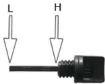
natural_image
Close-up of a mechanical device with warning symbols and circular arrows indicating cycle (no readable text or labels)natural_image
Close-up of a mechanical assembly under a structural beam, showing no visible text or symbolsnatural_image
Close-up of a black industrial machine with directional arrows indicating rotation or cycle (no text or symbols visible)natural_image
Close-up of a black automotive engine component with visible exhaust pipe and circular emblem (no text or symbols)natural_image
Close-up of a mechanical component with circular base and warning symbol, surrounded by curved arrows indicating rotation (no readable text or symbols)4) Panel sterujący
natural_image
Close-up of a mechanical assembly with visible components and no readable text or symbolsnatural_image
Close-up of a mechanical assembly with visible components and no readable text or symbolsnatural_image
Close-up of a hand adjusting a mechanical component with a tool (no visible text or symbols)natural_image
Close-up of a mechanical component with a hand holding a cylindrical part (no visible text or symbols)
natural_image
Close-up of a mechanical assembly under a structural beam, showing no visible text or symbols- Posuňte spínač motoru ON/OFF (11) do polohy "I".

natural_image
Close-up of a mechanical device with circular components and directional arrows indicating rotation (no readable text or symbols)4) Ovládací panel
LED indikátor chodu
natural_image
Close-up of a mechanical assembly with visible components and no readable text or symbolsnatural_image
Close-up of a black industrial machine component with visible hydraulic heads and mounting brackets (no text or symbols)natural_image
Close-up of a hand adjusting a mechanical component with a tool (no visible text or symbols)natural_image
Close-up of a hand inserting a dark object into a mechanical component (no visible text or symbols)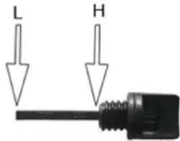
natural_image
Close-up of a mechanical device with warning symbols and circular arrows indicating cycle (no readable text)natural_image
Close-up of a mechanical assembly with hoses and components, no visible text or symbolsnatural_image
Close-up of a black industrial machine with directional arrows indicating flow or movement (no text or symbols visible)natural_image
Close-up of a black industrial engine component with visible exhaust pipe and valve (no text or symbols)natural_image
Close-up of a mechanical device with circular components and directional arrows indicating rotation or cycle (no readable text or symbols)natural_image
Close-up of a mechanical assembly with visible components and no readable text or symbolsnatural_image
Close-up of a black industrial machine component with visible hydraulic cylinder and control panel (no text or symbols)natural_image
Close-up of a mechanical assembly under a structural beam, showing no visible text or symbolsnatural_image
Close-up of a black industrial machine with directional arrows indicating rotation or cycle (no text or symbols visible)natural_image
Close-up of a black automotive engine component with visible exhaust pipe and circular emblem (no text or symbols)natural_image
Close-up of a mechanical device with circular components and directional arrows indicating motion (no readable text or symbols)natural_image
Close-up of a mechanical assembly with visible components and no readable text or symbolsnatural_image
Close-up of a hand adjusting a mechanical component with a tool (no visible text or symbols)natural_image
Close-up of a hand inserting a black hole into a mechanical component (no visible text or symbols)
natural_image
Close-up of a mechanical device with warning symbols and circular arrows indicating cycle (no readable text or labels)natural_image
Industrial machinery setup with a mechanical component and piping (no visible text or symbols)natural_image
Close-up of a black industrial machine with directional arrows indicating flow or movement (no text or symbols visible)natural_image
Close-up of a black industrial engine component with visible exhaust pipe and valve (no text or symbols)natural_image
Close-up of a mechanical device with circular components and directional arrows indicating rotation or cycle (no readable text or symbols)4) Panel de control
natural_image
Close-up of a mechanical assembly with visible gears and components (no text or symbols)natural_image
Close-up of a black industrial machine component with visible hydraulic heads and mounting brackets (no text or symbols)natural_image
Close-up of a hand adjusting a mechanical component with no visible text or symbolsnatural_image
Close-up of a mechanical component with a cylindrical opening and a hand holding a tool (no visible text or symbols)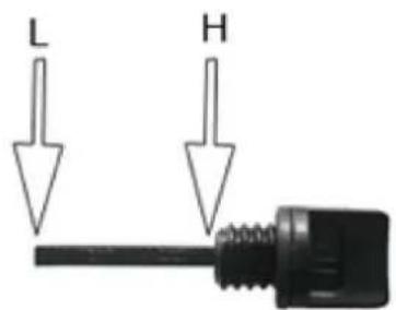
natural_image
Close-up of a black industrial machine with directional arrows indicating rotation or cycle (no text or symbols visible)natural_image
Close-up of a black automotive engine component with visible exhaust pipe and circular emblem (no text or symbols)natural_image
Close-up of a mechanical device with circular components and directional arrows indicating rotation (no readable text or symbols)4) Kezelőpanel
Futásjelző LED
natural_image
Close-up of a mechanical assembly with visible components and mounting brackets (no text or symbols)natural_image
Close-up of a hand adjusting a mechanical component with a tool (no visible text or symbols)natural_image
Close-up of a hand inserting a plug into a mechanical component (no visible text or symbols)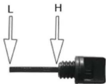
natural_image
Close-up of a mechanical assembly under a structural beam, showing no visible text or symbols- Flyt motorens ON/OFF-kontakt (11) til position "I".
- Flyt chokeren (2) til position I∅I (hvis motoren er varmet op, så ignorer dette trin).

natural_image
Close-up of a black industrial machine with directional arrows indicating rotation or cycle (no text or symbols visible)natural_image
Close-up of a black industrial engine component with visible exhaust pipe and valve (no text or symbols)natural_image
Close-up of a mechanical assembly with visible components and no readable text or symbolsnatural_image
Close-up of a mechanical device with a black housing and control panel (no visible text or symbols)• Fiern filterelementerne.
natural_image
Close-up of a hand adjusting a mechanical component with a tool (no visible text or symbols)natural_image
Close-up of a hand holding a small cylindrical object, possibly a mechanical component or tool, with no visible text or symbols.
natural_image
Close-up of a mechanical device with warning symbols and circular arrows indicating cycle (no readable text)natural_image
Close-up of a black industrial machine with directional arrows indicating rotation or cycle (no text or symbols visible)natural_image
Close-up of a black automotive engine component with visible exhaust pipe and circular emblem (no text or symbols)natural_image
Close-up of a mechanical device with circular components and directional arrows indicating rotation (no readable text or symbols)4) Ohjauspaneeli
natural_image
Close-up of a mechanical assembly with visible components and no readable text or symbolsnatural_image
Close-up of a black industrial machine component with visible hydraulic heads and mounting brackets (no text or symbols)- Irrota suodatinelementit.
natural_image
Close-up of a hand adjusting a mechanical component with no visible text or symbolsNL
natural_image
Black-and-white photo of a mechanical device with a curved pipe and housing, no visible text or symbols- Zet de AAN/UIT-schakelaar van de motor (11) in stand "I".
natural_image
Close-up of a black industrial machine with directional arrows indicating flow or movement (no text or symbols visible)natural_image
Close-up of a car engine bay with visible exhaust pipe and valve (no text or symbols)- Duw de choke (2) weer terug nadat de motor is gestart.
BELANGRIJK!
- Sluit de brandstofkraan (10)
natural_image
Close-up of a mechanical device with circular components and directional arrows indicating rotation (no readable text or symbols)4) Besturingspaneel
natural_image
Close-up of a mechanical assembly with visible components and no readable text or symbolsnatural_image
Close-up of a mechanical device with a black housing and visible components, no text or symbols present.natural_image
Close-up of a hand adjusting a mechanical component with a tool (no visible text or symbols)natural_image
Close-up of a mechanical component with a hand holding a cylindrical part (no visible text or symbols)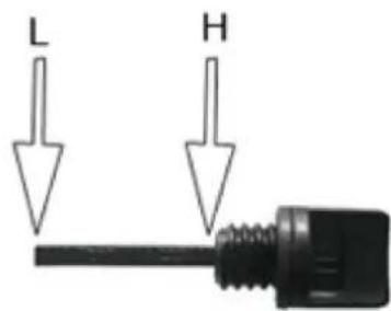
d) Stram til oljepeilepinnen (7).

natural_image
Close-up of a mechanical device with warning symbols and circular arrows indicating cycle (no readable text)natural_image
Close-up of a mechanical assembly under a structural beam, showing no visible text or symbolsnatural_image
Close-up of a black industrial machine with directional arrows indicating rotation or cycle (no text or symbols visible)natural_image
Close-up of a black automotive engine component with visible exhaust pipe and circular emblem (no text or symbols)• Steng drivstoffkranen (10)

natural_image
Close-up of a mechanical device with circular components and directional arrows indicating rotation or cycle (no readable text or symbols)4) Styrepanel
Kjør Indikator LED
LED for lav oljeindikator
natural_image
Close-up of a mechanical assembly with visible components and no readable text or symbolsnatural_image
Close-up of a mechanical device with a black housing and control panel (no visible text or symbols)• Fjern filterelementene.
natural_image
Close-up of a hand adjusting a mechanical component with a tool (no visible text or symbols)natural_image
Close-up of a hand inserting a cylindrical component into a mechanical housing (no visible text or symbols)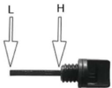
natural_image
Close-up of a mechanical assembly under a structural beam, showing no visible text or symbolsnatural_image
Close-up of a black industrial machine with directional arrows indicating rotation or cycle (no text or symbols visible)natural_image
Close-up of a black automotive engine component with visible exhaust pipe and circular emblem (no text or symbols)natural_image
Close-up of a mechanical device with circular components and directional arrows indicating rotation (no readable text or symbols)4) Kontrollpanel
Körindikator LED
natural_image
Close-up of a mechanical assembly with visible components and no readable text or symbolsnatural_image
Close-up of a hand adjusting a mechanical component with a tool (no visible text or symbols)natural_image
Close-up of a hand inserting a black hole into a mechanical component (no visible text or symbols)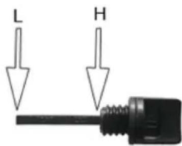
natural_image
Close-up of a mechanical device with warning symbols and circular arrows indicating cycle (no readable text)natural_image
Close-up of a mechanical assembly with a cylindrical component and curved pipe (no visible text or symbols)natural_image
Close-up of a black industrial machine with directional arrows indicating flow or movement (no text or symbols visible)natural_image
Close-up of a black industrial engine component with visible exhaust pipe and valve (no text or symbols)natural_image
Close-up of a mechanical device with circular components and directional arrows indicating rotation or cycle (no readable text or symbols)natural_image
Close-up of a mechanical assembly with visible components and no readable text or symbolsnatural_image
Close-up of a mechanical assembly with a black component and motor (no visible text or symbols)natural_image
Close-up of a hand adjusting a mechanical component with a tool (no visible text or symbols)natural_image
Close-up of a mechanical component with a hand holding a cylindrical part (no visible text or symbols)
d) Utiahnite mierku oleja (7).

natural_image
Close-up of a mechanical assembly under a structural beam, showing components like a valve and housing (no visible text or symbols)- Posuňte vypínač motora (11) do polohy "I".

- Posuňte sýtič (2) do polohy I∅l (ak sa motor zahrial, tento krok ignorujte).

natural_image
Close-up of a black industrial machine with directional arrows indicating rotation or cycle (no text or symbols visible)natural_image
Close-up of a black automotive engine component with visible exhaust pipe and circular emblem (no text or symbols)- Po naštartovaní motora opät zatlačte sýtič (2).
DÔLEŽITÉ!
natural_image
Close-up of a mechanical device with circular components and directional arrows indicating rotation (no readable text or symbols)4) Ovládací panel
LED indikátor chodu
- LED indikátor napájania (zelený) sa rozsvieti, ked'je k dispozícii napájanie výstupov.
natural_image
Close-up of a mechanical assembly with visible components and no readable text or symbolsnatural_image
Close-up of a mechanical assembly with a black component and housing (no visible text or symbols)For the disposal of the device please consider and act according to the national and local rules and regulations.
CONTACT
expondo Polska sp. z o.o. sp. k.