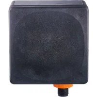
R2D201 - Radar sensor IFM - Free user manual and instructions
Find the device manual for free R2D201 IFM in PDF.


User questions about R2D201 IFM
0 question about this device. Answer the ones you know or ask your own.
Ask a new question about this device
Download the instructions for your Radar sensor in PDF format for free! Find your manual R2D201 - IFM and take your electronic device back in hand. On this page are published all the documents necessary for the use of your device. R2D201 by IFM.
USER MANUAL R2D201 IFM
Operating instructions
Radar area sensor with CAN
R2Dx
Contents
1 Preliminary note.... 3
1.1 Symbols used.... 3
1.2 Warnings.... 3
1.3 Safety symbols on the unit 3
1.4 Open source information 3
2 Safety instructions 5
2.1 Safety note on high-frequency electromagnetic radiation 5
2.2 Cybersecurity.... 6
3 Intended use 7
3.1 Application area 7
3.2 Restrictions of the application area 9
3.3 Impermissible use.... 10
4 Getting started 11
5 Function 12
5.1 Measuring principle 12
5.2 Operating modes 12
5.3 Overview.... 13
5.3.1 R2D101 13
5.3.2 R2D103 13
5.3.3 R2D201 13
5.3.4 R2D203 14
5.3.5 R2D205 14
5.4 CAN.... 14
6 Mounting 15
6.1 Mounting instruction.... 15
6.2 Mechanical design 16
6.3 Mounting with clamp 16
6.4 Mounting with mounting bracket.... 17
7 Electrical connection 19
8 Installation 20
9 Operating and display elements.... 21
9.1 LED states 21
10 Set-up 22
11 Parameter setting.... 23
11.1 Setting in distance mode 24
11.2 Setting in area mode 25
11.3 Selection rules.... 26
12 Troubleshooting.... 27
13 Maintenance, repair and disposal 28
14 Factory setting.... 29
Glossary 30
1 Preliminary note
You will find instructions, technical data, approvals and further information using the QR code on the unit / packaging or at documentation.ifm.com.
1.1 Symbols used
√ Requirement
Instruction
Reaction, result
bold Designation of keys, buttons or indications
→ Cross-reference without link
→ Cross-reference with link

Important note
Non-compliance may result in malfunction or interference

Information
Supplementary note
1.2 Warnings
Warnings indicate the possibility of personal injury and damage to property. This enables safe product handling. Warnings are graded as follows:

WARNING
Warning of serious personal injury
▷ If the warning is not observed, fatal and serious injuries are possible.

CAUTION
Warning of minor to moderate personal injury
▷ If the warning is not observed, minor to moderate injuries are possible.

ATTENTION
Warning of damage to property
▷ If the warning is not observed, damage to property is possible.
1.3 Safety symbols on the unit

• Electric supply must correspond to IEC 61010-1, chapter 9.4 - Limited-energy circuit.

Device of protection class III. Only for operation in SELV/PELV circuits.
1.4 Open source information
This product can contain Free Software or Open Source Software from various software developers which is subject to the following licenses: General Public License version 1, version 2 and version 3 (General Public License version 3 in conjunction with the GNU Compiler Collection Runtime Library Exception ver-
sion 3.1), Lesser General Public License version 2.1, Lesser General Public License version 3, Berkeley Software Distribution (BSD-2-Clause, BSD-3-Clause, BSD-4-Clause), MIT-License (MIT), Python Software Foundation License 2.0, Pearl Artistic License and Artistic License 2.0, Microsoft Public License, Apache Software License Version 1.0, 1.1 und 2.0, ISC License, libpng License, zlib License, the Academic Free License version 2.1, Mozilla Public License 2.0.
For the components subject to the General Public License in their respective versions the following applies:
This program is free software: you can redistribute it and/or modify it under the terms of the GNU General Public License as published by the Free Software Foundation. If version 1 applies to the software: either version 1 of the License or (at your option) any later version; if version 2 (or 2.1) applies to the software: either version 2 (or 2.1) of the License or (at your option) any later version; if version 3 applies to the software: either version 3 of the License or (at your option) any later version. The following disclaimer of the software developers applies to the software components that are subject to the General Public License or the implied warranty of MERCHANTABILITY or FITNESS FOR A PARTICULAR PURPOSE. See the GNU General Public License and the GNU Lesser General Public License for more details.
The responsibility of ifm electronic gmbh for ifm products, in the case of product-specific software, remains unaffected by the above disclaimer. Please note that the firmware for the ifm products is in some cases provided free of charge. The price of the ifm products has then to be paid for the respective device itself (hardware) and not for the firmware. For the latest information on the license agreement for your product please visit www.ifm.com
For binaries that are licensed under any version of the GNU General Public License (GPL) or the GNU LG-PL or Mozilla Public License 2.0 you may obtain the complete corresponding source code of the GPL software from us by sending a written request to: opensource@ifm.com or to ifm electronic gmbh, Friedrichstraße 1, 45128 Essen, Germany.
We charge €30 for each request. Please write “source for product Y” in the memo line of your payment. Your request should include (i) the name of the covered binary, (ii) the name and the version number of the ifm product, (iii) your name and (iv) your return address.
The following applies to components covered by the General Public License in their respective versions. This offer is valid to anyone in receipt of this information. This offer is valid for at least three years (from the date you received the GPL/LGPL covered code).

For more open source information see: documentation.ifm.com.
2 Safety instructions
- The unit described is a subcomponent for integration into a system.
- The system architect is responsible for the safety of the system.
-
The system architect undertakes to perform a risk assessment and to create documentation in accordance with legal and normative requirements to be provided to the operator and user of the system. This documentation must contain all necessary information and safety instructions for the operator, the user and, if applicable, for any service personnel authorised by the architect of the system.
-
Read this document before setting up the product and keep it during the entire service life.
- The product must be suitable for the corresponding applications and environmental conditions without any restrictions.
- Only use the product for its intended purpose (→ Intended use).
- If the operating instructions or the technical data are not adhered to, personal injury and/or damage to property may occur.
- The manufacturer assumes no liability or warranty for any consequences caused by tampering with the product or incorrect use by the operator.
- Installation, electrical connection, set-up, operation and maintenance of the product must be carried out by qualified personnel authorised by the machine operator.
- Protect units and cables against damage.
2.1 Safety note on high-frequency electromagnetic radiation
Under application-specific conditions, the risk for the user may differ depending on the installation situation and the device settings.
The system architect/operator is required to carry out a hazard analysis and to take appropriate measures for the protection of persons. In particular national regulations also have to be adhered to. Possible protective measures may include guaranteed minimum distances of a user, access controls and user training.

WARNING
Operation of this device can cause radio interference in residential areas.
▷ The device emits high-frequency electromagnetic waves that may interfere with the operation of electronic devices in the vicinity, including pacemakers, hearing aids and defibrillators.
▶ Due to human exposure regulations, a minimum distance of 20 cm must be maintained between the device and persons.
▶ If you have a pacemaker or other implanted medical product, do not use the device without first consulting your doctor or the manufacturer of your medical product. Keep a safe distance between the device and your medical devices and refrain from further use of the device if you observe permanent impairment of your medical product.
2.2 Cybersecurity
Installation
The device is suitable for operation in a secure environment according to IEC 62443-1-1.
The device was designed for operation behind a firewall.
▶ Carry out a risk assessment of the system according to IEC 62443-1-1.
▶ Take measures to ensure physical security.
Operation
▶ Observe the security functions described in the product documentation and the recommendations for their use.
Maintenance
- ▶ Back up system configuration and system data in accordance with your company’s change management processes.
Decommissioning
▶ Ensure that no sensitive information can fall into unauthorised hands.
▶ Always reset the system settings to the factory settings before decommissioning the device.
3 Intended use
3.1 Application area
Based on FMCW radar, the device monitors an area without contact and detects the distance, position and velocity of stationary and moving objects. Target areas, switching limits and zones (ROI) can be defined.
The sensor has been designed for industrial use (permanently installed device). However, it can also be used and operated in mobile mode (sensor moves) if the corresponding requirements are met.
The dimension of the detection range of the device depends on the target object to be detected. The detection ranges for defined targets (corner reflectors) are defined in the technical data sheet of the device.
The setting of the device as well as the visualisation of the detection range can be done via the Vision Assistant or moneo.

The application area of the device depends on the base frequency used and the country in which it is operated. Applicable national approval restrictions must be checked prior to set-up of the device. Country-specific features must be taken into account when operating the device. Operation of the device is only permitted in the countries listed in the package insert “Radio approval”. When operating the device in countries that are not on the list, interference with protected frequency ranges may occur.
For USA, Canada, Ecuador:
Devices operating at a base frequency of 60 GHz can be used for static or mobile applications, regardless of the specific application. Devices used on aircraft are permitted only when the aircraft is on the ground. The devices are not permitted to be used on satellites. The following devices belong to this group:
• R2D103
Devices operating at a base frequency of 77 GHz are intended for vehicular use. The following devices belong to this group:
- R2D201
For Chile:
Devices operating at a base frequency of 60 GHz are intended for static, immobile applications only. The device may move within a fixed installation. This includes stationary applications for collision avoidance, level measurement, object detection, flow measurement and area monitoring. The devices are not approved for vehicular use. The following devices belong to this group:
• R2D103
Devices operating at a base frequency of 77 GHz are intended for vehicular use. The following devices belong to this group:
• R2D201
For Europe, Namibia, South Africa, Cameroon, Mongolia, Paraguay:
Devices operating at a base frequency of 60 GHz can be used for static, mobile or portable applications, regardless of the specific application. The following devices belong to this group:
• R2D101
Devices operating at a base frequency of 77 GHz are intended for fixed and mobile transport and traffic telematics (TTT) applications only. This includes, for example, obstacle detection, monitoring of tunnels and level crossings and parking assistance. The following devices belong to this group:
• R2D201
For Australia, New Zealand:
Devices operating at a base frequency of 60 GHz or 77 GHz can be used for static, mobile or portable applications, regardless of the specific application. The following devices belong to this group:
- R2D101 / R2D201
For Brazil:
Devices operating at a base frequency of 77 GHz are intended for vehicular use. The following devices belong to this group:
• R2D201
For Argentina:
Devices operating at a base frequency of 60 GHz can be used for static, mobile or portable applications, regardless of the specific application. The following devices belong to this group:
• R2D101
Devices operating at a base frequency of 76 GHz are intended for vehicular use.
The following devices belong to this group:
• R2D205
For India:
Devices operating at a base frequency of 76 GHz can be used for static, mobile or portable applications, regardless of the specific application. The following devices belong to this group:
- R2D205
For Japan:
Devices operating in the 79 GHz band can be used for static, mobile or portable applications, regardless of the specific application. The following devices belong to this group:
• R2D203
For Mexico:
Devices operating at a base frequency of 60 GHz can be used for static, mobile or portable applications, regardless of the specific application. The following devices belong to this group:
• R2D101
Devices operating at a base frequency of 77 GHz are intended for fixed and mobile transport and traffic telematics (TTT) applications only. This includes, for example, obstacle detection, monitoring of tunnels and level crossings and parking assistance. The following devices belong to this group:
• R2D201
For Singapore:
Devices operating at a base frequency of 60 GHz can be used for static, mobile or portable applications, regardless of the specific application. The following devices belong to this group:
• R2D101
Devices operating at a base frequency of 77 GHz are intended for static transport and traffic telematics (TTT) applications and ground-based vehicular use only. This includes, for example, obstacle detection, monitoring of tunnels and level crossings and parking assistance. The following devices belong to this group:
• R2D205
For Israel:
Devices operating at a base frequency of 60 GHz can be used for static, mobile or portable applications, regardless of the specific application. The following devices belong to this group:
- R2D101
For Morocco:
Devices operating at a base frequency of 77 GHz are intended for fixed and mobile transport and traffic telematics (TTT) applications only. This includes, for example, obstacle detection, monitoring of tunnels and level crossings and parking assistance. The following devices belong to this group:
• R2D201
For Malaysia:
Devices operating at a base frequency of 77 GHz are intended for vehicular use. The following devices belong to this group:
• R2D201

Notes relevant for approval: Package insert of the device and documentation.ifm.com EU declaration of conformity and approvals: documentation.ifm.com
- The device may only be operated in countries for which it has been approved.
- If the device is passed on, the recipient must be informed of applicable national approval restrictions.
Electromagnetic compatibility (EMC):
The device is designed for use in industrial environments and mobile machines.
• This product may cause radio interference in domestic areas.
• If required, take appropriate EMC screening measures.

The device must be installed in such a way that it cannot be touched by unauthorised persons.
For the scope of validity cRUus:
The electrical supply must only be made via SELV/PELV circuits. Supply of the device to limited energy according to chapter 9.4 UL 61010-1. The external circuits have to be isolated as required by figure 102 in UL 61010-2-201.
The device safety is rated for use under the following operating conditions:
- indoor use
• Altitude up to 2000 m
• Maximum relative humidity 90 %, non-condensing - Pollution degree 2
Use UL-certified cables of category CYJV 2/7/8 with suitable ratings for connecting the device.
No special treatment is needed for cleaning the device.
3.2 Restrictions of the application area
▷ The device emits high-frequency electromagnetic waves that are reflected by objects and received and evaluated by the device. The quality of the received energy depends on various object-specific parameters (RCS). Large objects made of metal, for example, are characterised by a high RCS value and can be detected very well by the radar sensor. Objects made of plastics have a small RCS value and cannot always be reliably detected.
Objects with a high RCS value (metals, stone walls) can negatively influence the measurement result and eliminate target objects with a lower RCS value or create false targets.
3.3 Impermissible use
Use that goes beyond the intended use of the device and is outside the technical specification (see data sheet) is not permitted.
The device does not comply with the applicable safety standards for machinery and is therefore not approved as a safety component.
▶ Only use the operating and adjusting devices (accessories) indicated in the operating instructions.

WARNING
The device does not have self-monitoring redundant circuits and is therefore not intended for operator protection applications. In the event of a defect or device failure, unpredictable switching behaviour of the output may occur.
▷ Death or serious irreversible injuries may result.
▶ Do not use this device for operator protection.

WARNING
This device is not suitable for use in hazardous areas.
▷ Death or serious irreversible injuries may result.
▶ Do not use this device in hazardous areas.

WARNING
Any impermissible use can lead to dangerous situations.
▷ Death or serious irreversible injuries may result.
▶ Use the device only in accordance with the “Intended use”.
▶ Comply with the indications in the operating instructions.
▶ Immediately remove damaged products from service.
4 Getting started
For fast set-up, carry out the following steps:
- Install the device so that it can detect the required area and is not obscured. ➞ 15
- Install the CANfox software according to the CANfox operating instructions, as well as the current version of the Vision Assistant.
- Establish a connection to the device using CANfox.
- Use the Vision Assistant to make the required settings on the device.

The software is required to configure the device. The software can be downloaded at www.ifm.com.
5 Function
5.1 Measuring principle
The radar sensor determines the distance, position, speed and direction of movement of objects based on FMCW (Frequency Modulated Continuous Wave) radar.
The device emits high-frequency electromagnetic waves which are reflected by the object. The reflected energy is picked up and evaluated by the device's receiving antenna.

Fig. 1: Measuring principle
1: Radar lobe
2: Object
5.2 Operating modes

The device can only be configured via CAN interface. The software can be downloaded at www.ifm.com.
Depending on the device, up to two different operating modes can be set. These differ in the maximum distance, distance resolution, maximum velocity and velocity resolution.

Not all devices have the option of changing the operating mode. The operating modes and exact technical data are listed in the technical data sheet for the respective device.

If the velocity limits are exceeded, the counter starts over, i.e. the measured value does not correspond to the actual velocity.
5.3 Overview
5.3.1 R2D101
| Art. no.: | R2D101 |
| Type designation: | R2DAAOOKG/US/CAN |
| Angle of aperture: | ± 70° horizontal / ± 25° vertical |
| Function: | radar distance / area sensor |
| Operating frequency: | 60-64 GHz |
| Type: | rectangular |
| Radiated transmitter power (e.i.r.p.) and spectral densities (e.i.r.p.): | → see data sheet |

The angle of aperture was determined with a corner reflector (E23013) at a distance of 5 m.
5.3.2 R2D103
| Art. no.: | R2D103 |
| Type designation: | R2DADOOKG/US/CAN |
| Angle of aperture: | ± 70° horizontal / ± 25° vertical |
| Function: | radar distance / area sensor |
| Operating frequency: | 60-64 GHz |
| Type: | rectangular |
| Radiated transmitter power (e.i.r.p.) and spectral densities (e.i.r.p.): | → see data sheet |

The angle of aperture was determined with a corner reflector (E23013) at a distance of 5 m.
5.3.3 R2D201
| Art. no.: | R2D201 |
| Type designation: | R2DBAOKG/US/CAN |
| Angle of aperture: | ± 70° horizontal / ± 15° vertical |
| Function: | radar distance / area sensor |
| Operating frequency: | 77-81 GHz |
| Type: | rectangular |
| Radiated transmitter power (e.i.r.p.) and spectral densities (e.i.r.p.): | → see data sheet |

The angle of aperture was determined with a corner reflector (E23013) at a distance of 5 m.
5.3.4 R2D203
| Art. no.: | R2D203 |
| Type designation: | R2DBDOOKG/US/CAN |
| Angle of aperture: | ± 70° horizontal / ± 15° vertical |
| Function: | radar distance / area sensor |
| Operating frequency: | 77-81 GHz |
| Type: | rectangular |
| Radiated transmitter power (e.i.r.p.) and spectral densities (e.i.r.p.): | → see data sheet |

The angle of aperture was determined with a corner reflector (E23013) at a distance of 5 m.
5.3.5 R2D205
| Art. no.: | R2D205 |
| Type designation: | R2DBBOOKG/US/CAN |
| Angle of aperture: | ± 70° horizontal / ± 15° vertical |
| Function: | radar distance / area sensor |
| Operating frequency: | 76-77 GHz |
| Type: | rectangular |
| Radiated transmitter power (e.i.r.p.) and spectral densities (e.i.r.p.): | → see data sheet |

The angle of aperture was determined with a corner reflector (E23013) at a distance of 5 m.
5.4 CAN
The sensor features a standardised SAE J1939 interface. Parameter setting, diagnostics and firmware update are made via the CAN interface. All measured values and parameter groups can be accessed via the J1939 protocol. For a detailed description of the SAE J1939 protocol and the parameter settings, refer to the software manual.
6 Mounting

ATTENTION
Radiated electromagnetic field strengths
The device emits high-frequency electromagnetic waves.
It complies with the country-specific limits for the public and workers.
▶ Disconnect the device in the vicinity of medical equipment.
6.1 Mounting instruction
▶ Storage at high air humidity: Observe the notes in the technical data sheet.
▶ Ensure mechanical decoupling when installing the device to prevent the sensor from vibrating.
▶ Avoid installation in heavily polluting areas of the machine.
▶ Do not paint the device.
▶ Provide strain relief for suitable M12 socket.

More information on radar sensor accessories can be found at www.ifm.com.

If there is a risk of damage to the device, it must be installed in such a way that it can only be accessed for occasional work, such as mechanical adjustments, and cannot be touched by unauthorised persons.

Device performance can be affected if positioned in the immediate vicinity of powerful HF emission sources such as welding transformers.
The mounting accessories described in the following sections are recommended for correct installation.
Large metallic objects in the immediate vicinity of the sensing face of the sensor can have a negative effect on the measured signal.
▶ When mounting, ensure that there are no unwanted objects within the sensor's field of view (FOV).
▶ Observe the horizontal and vertical angles of aperture of the respective device.
▶ Lateral elements must be outside the detection angles.
Vertical angle of aperture

Horizontal angle of aperture

| Vertical angle of aperture | Horizontal angle of aperture |
| 1: ± 25° | 2: ± 70° |
6.2 Mechanical design

Fig. 2: Mechanical design
1: Connection (can be rotated by 270° )
2: Sensing face
6.3 Mounting with clamp
▶ Insert the M5 screws through the through holes of the device and guide them into the threaded M5 holes of the bracket. Tightening torque max. 3.0 Nm.
▶ Fix the clamp to the bracket (E23011).

Fig. 3: Mounting
1: M5 screws
2: Through holes of the radar sensor
3: Bracket
4: Clamp
5: M5 washers

Fig. 4: Completed installation
6.4 Mounting with mounting bracket
By means of the mounting bracket (E23009) the mounting angle of the sensor can be adjusted. A maximum angle of 45° can be set.

Fig. 5: Example
By means of the mounting bracket (E23010) the mounting angle of the sensor can be adjusted. A maximum angle of 20° can be set.

Fig. 6: Example
7 Electrical connection

The unit must be connected by a qualified electrician.
Observe the national and international regulations for the installation of electrical equipment.
Voltage supply according to SELV, PELV.
▶ Disconnect power.
▶ Connect the unit as follows:

Fig. 7: Wiring diagram
| Pin | Assignment | Description |
| 1: | CAN_SHLD | CAN shield |
| 2: | CAN_V+ | Supply voltage 24 V DC (+UB) |
| 3: | CAN_GND | Ground |
| 4: | CAN_H | High bus cable |
| 5: | CAN_L | Low bus cable |

Recommendation: Use pre-configured connection cables / sockets, see accessories at www.ifm.com.

The device can be damaged by insufficiently tightened M12 connectors.
The IP rating indicated in the data sheet is only guaranteed if the
M12 connectors are firmly screwed.
▶ Screw the M12 connectors tightly to the device according to the instructions in the corresponding technical data sheet.

For cable lengths longer than 30 m use an additional protection against surge voltages to IEC 61000-4-5.

In the first millisecond after switching on the sensor, the current consumption of the device is increased.
If several radar sensors are connected to one voltage supply, this can lead to the current limitation being activated, especially when restarting after a power failure.
8 Installation
To be able to make full use of the device's functions, the ifm Vision Assistant software is required for parameter setting.
▶ Go to the download section at this link and download the ifm Vision Assistant software onto your computer.

The operation of the ifm Vision Assistant software is described in the software manual. ➕ software manual at www.ifm.com.
9 Operating and display elements

| 1: | 1x green / red LED | Status LED |
9.1 LED states
| LED behaviour | Description | Action |
| Status LED is green | Device is connected to the voltage supply and ready for operation | |
| Status LED flashing red (1 Hz) | Error (correctable by the operator) Troubleshooting | |
| Status LED is red | Serious error▶ Contact ifm support. Contact at www.ifm.com |
10 Set-up
After power on, the device is put into operation.
After approx. 3 s the device is ready for operation.
On delivery, the parameters are set to the factory setting.
The device is set using the ifm Vision Assistant software.
11 Parameter setting
The device parameters can be set in two ways:
- ifm Vision Assistant software (→ see software manual at www.ifm.com)
The coordinate system
The coordinate system is defined according to the right-hand rule.

Fig. 8: Schematic illustration in the coordinate system
1: X position
2: Y position
3: Z position
4: Distance
5: Target object

Fig. 9: Schematic illustration in the coordinate system
1: “Roll”
2: “Pitch”
The following statements apply to vertical mounting of the sensor.
The x coordinate corresponds to the longitudinal distance, with positive sign, pointing away from the centre of the sensing face of the radar sensor at the coordinate origin.
The y coordinate corresponds to the lateral expansion, output with positive signs to the left of the sensor and with negative signs to the right of the sensor, viewed in the positive x direction.
The z coordinate corresponds to the height, output above the sensor with a positive sign and below the sensor with a negative sign.
The device comes with integrated inclination measurement and can output information on its inclination angle. Tilting around the x axis is called “rolling” and tilting around the y axis is called “pitching”.
The velocity of the target object is output with a negative sign when the target object moves towards the sensor.
The velocity of the target object is output with a positive sign when the target object moves away from the sensor.

Fig. 10: Schematic illustration of the detection zone
1: Sensor
2: Detection zone
3: Moving objects
11.1 Setting in distance mode
The device has a horizontal angle of aperture of ±70° . The FOV of the sensor is variable and can be adjusted. The radar sensor is capable of detecting several targets simultaneously.
The maximum range of the device depends on the target object and the selected modulation. As an example, the figure shows the FOV of the device for three objects for the operating mode “Standard”.

For further information ➕ Software manual

Fig. 11: Top view
1: X axis [m]
2: Y axis [m]
3: Object: pedestrian (-10 dB)
4: Object: reflector 50 mm (0 dB)
5: Object: passenger car (10 dB)

Fig. 12: Side view
1: Z axis [m]
2: X axis [m]
3: Object: pedestrian (-10 dB)
4: Object: reflector 50 mm (0 dB)
5: Object: passenger car (10 dB)
11.2 Setting in area mode
Angle of aperture and range → 24, setting parameters differ.

For further information ➕ Software manual
11.3 Selection rules
You can choose between the following selection rules:
| Selection rule | Description |
| Shortest distance | The target closest to the sensor is selected. |
| Strongest power | The target that has the highest reflected energy is selected. |
| Strongest RCS | The target that has the strongest RCS is selected. |
| Highest absolute velocity | The target that has the highest absolute velocity is selected. |
| Longest distance | The target that is furthest away from the sensor is selected. |
12 Troubleshooting
| Possible cause | Solution |
| Ambient temperature too high | ▸ Reduce ambient temperature |
| Supply voltage outside the specification (→ technical data sheet) | ▸ Adjust supply voltage |
If the device behaves unexpectedly or incorrectly:
▶ Download and install the latest firmware and ifm Vision Assistant versions ➞ 20. Download at documentation.ifm.com.
▶ Disconnect the device from the voltage supply (restart)
▶ Reset to factory settings
If the problems persist:
▶ Contact the ifm support at www.ifm.com.
13 Maintenance, repair and disposal
If used correctly, the unit is maintenance-free.
▶ Keep the sensing face and any clear spaces free from deposits and foreign bodies.
It is not possible to repair the device.
Only the manufacturer is allowed to repair the unit.
▶ After use, dispose of the unit in an environmentally friendly way in accordance with the applicable national regulations.
14 Factory setting
The factory settings of the parameters are available at documentation.ifm.com.
Glossary
RCS
RCS stands for Radar Cross Section (radar signature) and is a measure of how well a target is detectable by radar, i.e. how much of the emitted energy is reflected from a target. The higher the RCS value, the better the reflectivity and thus the visibility of the target. The RCS value depends on factors such as material, size and angle of incidence, but not on the distance of the reflection target, as long as a reflection is not affected by the distance.
Vehicular use
Vehicular use means applications in the vicinity (not inside) a vehicle, where a vehicle is a platform that performs specific tasks to transport someone or something.
- 1 PRELIMINARY NOTE
- 1.1 SYMBOLS USED
- 1.2 WARNINGS
- 1.3 SAFETY SYMBOLS ON THE UNIT
- 1.4 OPEN SOURCE INFORMATION
- 2 SAFETY INSTRUCTIONS
- 2.1 SAFETY NOTE ON HIGH-FREQUENCY ELECTROMAGNETIC RADIATION
- 2.2 CYBERSECURITY
- 3 INTENDED USE
- 3.1 APPLICATION AREA
- 3.2 RESTRICTIONS OF THE APPLICATION AREA
- 3.3 IMPERMISSIBLE USE
- 4 GETTING STARTED
- 5 FUNCTION
- 5.1 MEASURING PRINCIPLE
- 5.2 OPERATING MODES
- 5.3 OVERVIEW
- 5.3.1 R2D101
- 5.3.2 R2D103
- 5.3.3 R2D201
- 5.3.4 R2D203
- 5.3.5 R2D205
- 5.4 CAN
- 6 MOUNTING
- 6.1 MOUNTING INSTRUCTION
- 6.2 MECHANICAL DESIGN
- 6.3 MOUNTING WITH CLAMP
- 6.4 MOUNTING WITH MOUNTING BRACKET
- 7 ELECTRICAL CONNECTION
- 8 INSTALLATION
- 9 OPERATING AND DISPLAY ELEMENTS
- 9.1 LED STATES
- 10 SET-UP
- 11 PARAMETER SETTING
- 11.1 SETTING IN DISTANCE MODE
- 11.2 SETTING IN AREA MODE
- 11.3 SELECTION RULES
- 12 TROUBLESHOOTING
- 13 MAINTENANCE, REPAIR AND DISPOSAL
- 14 FACTORY SETTING
Brand : IFM
Model : R2D201
Category : Radar sensor