
FWT03GATNMV1 - Air Conditioning DAIKIN - Free user manual and instructions
Find the device manual for free FWT03GATNMV1 DAIKIN in PDF.

User questions about FWT03GATNMV1 DAIKIN
0 question about this device. Answer the ones you know or ask your own.
Ask a new question about this device
Download the instructions for your Air Conditioning in PDF format for free! Find your manual FWT03GATNMV1 - DAIKIN and take your electronic device back in hand. On this page are published all the documents necessary for the use of your device. FWT03GATNMV1 by DAIKIN.
USER MANUAL FWT03GATNMV1 DAIKIN
Installation Manual Chilled Water Fan Coil Units
Installationshandbuch Kaltwasser-Ventilator Luftkühler
(Applicable for certified models only)

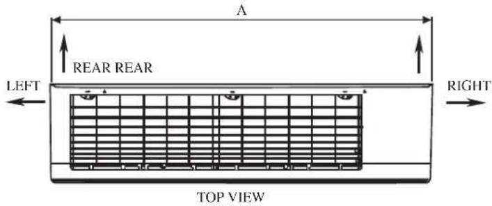
OUTLINE AND DIMENSIONS
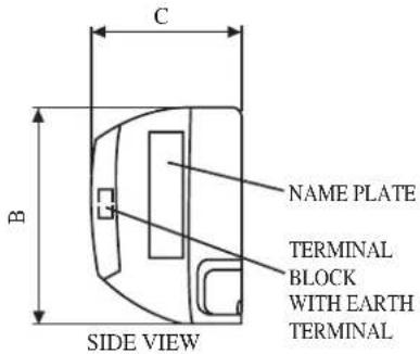
Indoor Unit
THE MARK (SHOWS)PIPING DIRECTION
text_image
A REAR REAR LEFT RIGHT TOP VIEW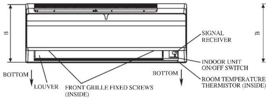
text_image
B BOTTOM LOUVER FRONT GRILLE FIXED SCREWS (INSIDE) BOTTOM SIGNAL RECEIVER INDOOR UNIT ON/OFF SWITCH ROOM TEMPERATURE THERMISTOR (INSIDE)FRONT VIEW
text_image
C B NAME PLATE TERMINAL BLOCK WITH EARTH TERMINAL SIDE VIEW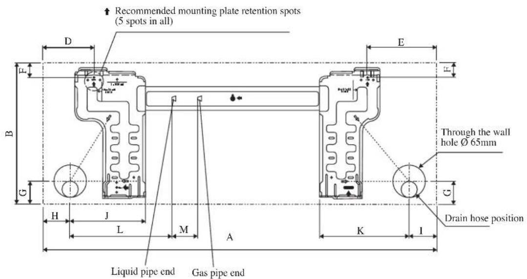
text_image
Recommended mounting plate retention spots (5 spots in all) Through the wall hole Ø 65mm Drain hose position Liquid pipe end Gas pipe endINSTALLATION PLATE FWT02/03/04
| DimensionModel | A | B | C | D | E | F | G | H | I | J | K | L | |
| FWT02/03/04 800 288 | 206 10 | 4 141 | 30 46 5 | 5 56 15 | 3 181 | 207 52 |
text_image
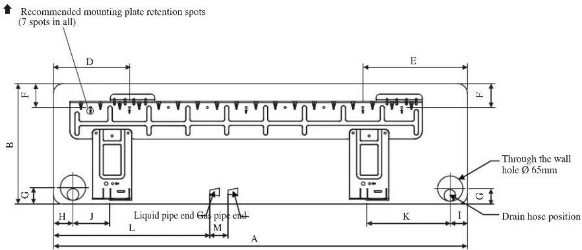
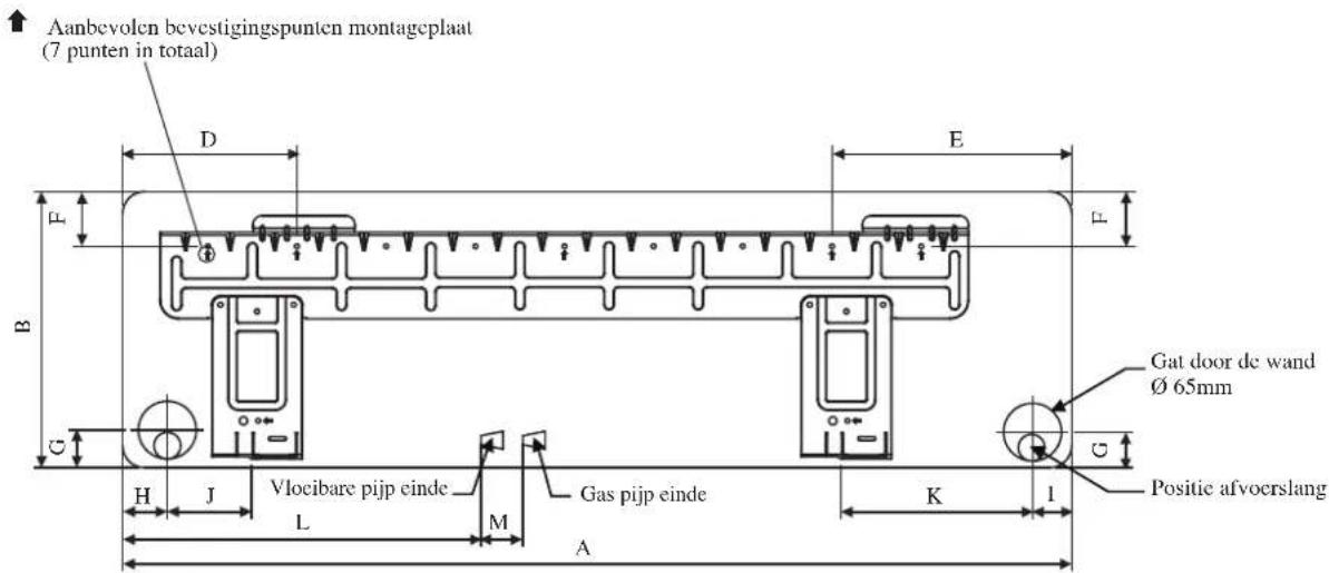
Recommended mounting plate retention spots (7 spots in all) D E F B C H J Liquid pipe end Gas pipe end- L M A K I Through the wall hole Ø 65mm Drain hose positionINSTALLATION PLATE FWT05/06
| Dimension Model | A | B | C | D | E | F | G | H | I | J | K | L | |
| FWT05/06 1065 310 224 190 | 173 61 | 40 45 | 48 91 2 | 19 580 | 45 |
All dimensions are in mm
INSTALLATION MANUAL
This manual provides the procedures of installation to ensure a safe and good standard of operation for the air conditioner unit. Special adjustment may be necessary to suit local requirements.
Before using your air conditioner, please read this instruction manual carefully and keep it for future reference. This appliance is intended to be used by expert or trained users in shops, in light industry and on farms, or for commercial use by lay persons.
This appliance is not intended for use by persons, including children, with reduced physical, sensory or mental capabilities, or lack of experience and knowledge, unless they have been given supervision or instruction concerning use of the appliance by a person responsible for their safety.
Children should be supervised to ensure that they do not play with the appliance.
SAFETY PRECAUTIONS
⚠ WARNING ⚠ CAUTION
- Installation and maintenance should be performed by qualified persons who are familiar with local code and regulation, and experienced with this type of appliance.
- All field wiring must be installed in accordance with the national wiring regulation.
- Ensure that the rated voltage of the unit corresponds to that of the name plate before commencing wiring work according to the wiring diagram.
- The unit must be GROUNDED to prevent possible hazard due to insulation failure.
- All electrical wiring must not touch the refrigerant piping, or any moving parts of the fan motors.
- Confirm that the unit has been switched OFF before installing or servicing the unit.
- Disconnect from the main power supply before servicing the air conditioner unit.
- DO NOT pull out the power cord when the power is ON. This may cause serious electrical shocks which may result in fire hazards.
- Keep the indoor and outdoor units, power cable and transmission wiring, at least 1m from TVs and radios, to prevent distorted pictures and static. {Depending on the type and source of the electrical waves, static may be heard even when more than 1m away}.
Please take note of the following important points when installing.
- Ensure that the drainage piping is connected properly.

If the drainage piping is not connected properly, it may cause water leakage which will dampen the furniture.
- Ensure that the unit's panel is closed after service or installation.

Unsecured panels will cause the unit to operate noisily.
- Sharp edges and coil surfaces are potential locations which may cause injury hazards.
Avoid from being in contact with these places. - Before turning off the power supply, set the remote controller's ON/OFF switch to the "OFF" position to prevent the nuisance tripping of the unit. If this is not done, the unit's fans will start turning automatically when power resumes, posing a hazard to service personnel or the user.
- Do not install the units at or near doorway.
- Do not operate any heating apparatus too close to the air conditioner unit or use in room where mineral oil, oil vapour or oil steam exist, this may cause plastic part to melt or deform as a result of excessive heat or chemical reaction.
- When the unit is used in kitchen, keep flour away from going into suction of the unit.
- This unit is not suitable for factory used where cutting oil mist or iron powder exist or voltage fluctuates greatly.
- Do not install the units at area like hot spring or oil refinery plant where sulphide gas exists.
- Ensure the color of wires of the outdoor unit and the terminal markings are same to the indoors respectively.
- IMPORTANT : DO NOT INSTALL OR USE THE AIR CONDITIONER UNIT IN A LAUNDRY ROOM.
- Don't use joined and twisted wires for incoming power supply.
- The equipment is not intended for use in a potentially explosive atmosphere.
NOTICE
Disposal requirement
Your air conditioning product is marked with this symbol. This means that electrical and electronic products shall not be mixed with unsorted household waste.
Do not try to dismantle the system yourself: the dismantling of the air conditioning system, treatment of the refrigerant, of oil and of other parts must be done by a qualified installer in accordance with relevant local and national legislation.
Air conditioners must be treated at a specialized treatment facility for re-use, recycling and recovery. By ensuring this product is disposed of correctly, you will help to prevent potential negative consequences for the environment and human health. Please contact the installer or local authority for more information.
Batteries must be removed from the remote controller and disposed of separately in accordance with relevant local and national legislation.
INSTALLATION DIAGRAM
text_image
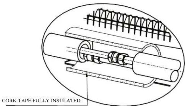
CORK TAPE FULLY INSULATEDINSULATION THROUGH OUT CHILLED WATER PIPING
INSTALLATION OF THE INDOOR UNIT
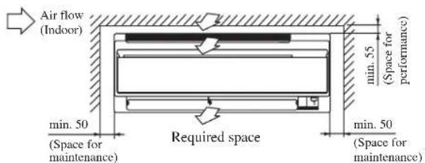
The indoor unit must be installed in such a way so as to prevent short circuit of the cool discharged air with the hot return air. Please follow the installation clearance shown in the figure. Do not place the indoor unit where there could be direct sunlight shining on it. Also, this location must be suitable for piping and drainage, and be away from doors or windows.
text_image
Air flow (Indoor) min. 50 (Space for maintenance) required space min. 50 (Space for maintenance) min. 55 (Space for performance)All dimensions are in mm

CAUTION
Do not install the unit at altitude over 2000m.
Air Purging
To prevent pump damage, the fan coil unit should not be energized until the coil and all water lines have been purged of air.
natural_image
Diagram showing airflow control components including fan, air gap, and fan valve (no text or labels)The Air Vent located inside the casing. Removed the casing and connect hose to the air vent while doing purging.

CAUTION
Ensure there is no water droplets go into the control box during purging process.
The indoor unit must be installed in such a way so as to prevent short circuit of the cool discharged air with the hot return air. Please follow the installation clearance shown in the figure. Do not place the indoor unit where there could be direct sunlight shining on it. Also, this location must be suitable for piping and drainage, and be away from doors or windows.
Right-side, right-back or right-bottom piping
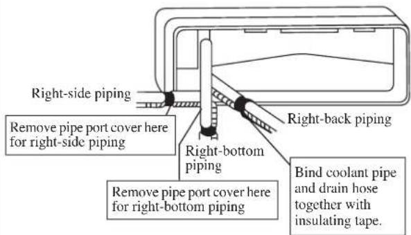
text_image
Right-side piping Remove pipe port cover here for right-side piping Right-back piping Right-bottom piping Remove pipe port cover here for right-bottom piping Bind coolant pipe and drain hose together with insulating tape.Left-side, left-back or left-bottom piping
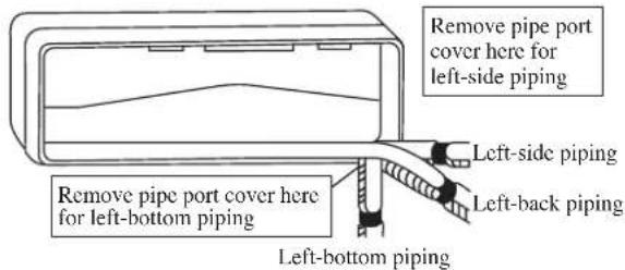
text_image
Remove pipe port cover here for left-side piping Left-side piping Remove pipe port cover here for left-bottom piping Left-back piping Left-bottom pipingMounting Installation Plate
Ensure that the wall is strong enough to withstand the weight of the unit. Otherwise, it is necessary to reinforce the wall with plates, beams or pillars.
Use the level gauge for horizontal mounting, and fix it with 5 suitable screws for FWT02/03/04 and 7 suitable screws for FWT05/06.
In case the rear piping draws out, drill a hole 65mm in diameter with a cone drill, slightly lower on the outside wall (see figure).
FWT02/03/04
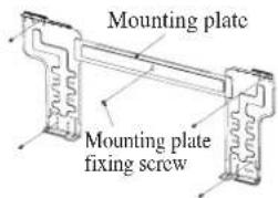
text_image
Mounting plate Mounting plate fixing screwFWT05/06
Mounting plate fixing screw
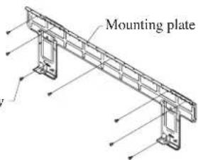
text_image
Mounting plateRecommended Mounting Plate Retention Spots And Dimensions
FWT02/03/04
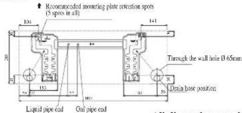
text_image
Recommended mounting plate retention spots (5 spots in all) 104 1-1 Through the wall hole Ø 65mm Liquid pipe end Gas pipe end 35° Denain hose position All lines are shownAll dimensions are in mm
FWT05/06
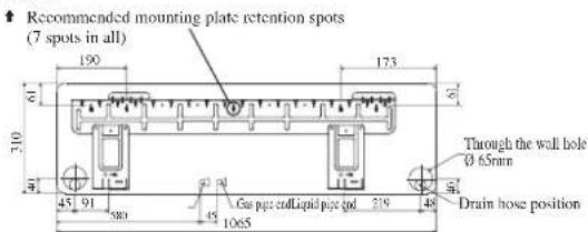
text_image
Recommended mounting plate retention spots (7 spots in all) 150 173 61 310 45 91 580 45 1065 Cu pipe edLiquid pipe 66 219 48 Through the wall hole Ø 6.5mm Drain hose positionAll dimensions are in mm
Hole with cone drill
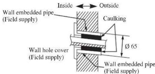
text_image
Inside Outside Wall embedded pipe (Field supply) Caulking Ø 65 Wall hole cover (Field supply) Wall embedded pipe (Field supply)Mount The Unit Onto The Installation Plate
Hook the indoor unit onto the upper portion of the installation plate (Engage the two hooks at the rear top of the indoor unit with the upper edge of the installation plate). Ensure that the hooks are properly seated on the installation plate by moving it to the left and right.
How To Attach The Indoor Unit
Hook the claws of the bottom frame to the mounting plate.
How To Remove The Indoor Unit
Push up the marked area (at the lower part of the front grille) to release the claws.
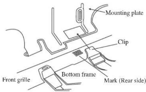
text_image
Mounting plate Clip Front grille Bottom frame Mark (Rear side)Hand indoor unit's hook here.
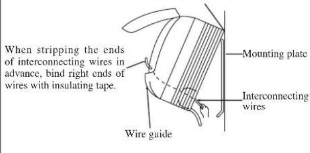
text_image
When stripping the ends of interconnecting wires in advance, bind right ends of wires with insulating tape. Mounting plate Interconnecting wires Wire guideWater Drainage Piping
The indoor drain pipe must be in a downward gradient for smooth drainage. Avoid situations that are likely to cause water to leak.
Water Drainage
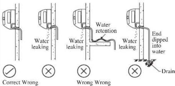
text_image
Water leaking Correct Wrong Water leaking Water retention Wrong Wrong Water leaking End dipped into water DrainCAUTION
- Do not install the unit at altitude over 2000m for both indoor & outdoor.
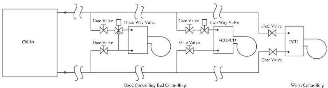
Water Piping Connection
The indoor unit is equipped with water outlet and inlet threaded connection. There is an air-vent for air purging that is fitted at the outlet water header.
3 ways valve is required for cycling off or bypass the chilled water.
Black steel pipe, polyuthrene pipe, PVC pipe and copper tube are recommended in field installation.
All types of piping and connection must be insulated by polyurethane (ARMAFLEX type or equivalent) to avoid condensation.
Do not use contaminated or damaged pipe and fitting for installation.
Some main fitting components are needed in the system to enhance the capacity and ease of service, such as gate valve, balancing valve, 2 ways or 3 ways valve, filter, strainer, etc.
flowchart
graph LR
    A["Chiller"] --> B["Gate Valve"]
    B --> C["Three Way Valve"]
    C --> D["FCU/FCU"]
    D --> E["FCU"]
    E --> F["Worst Controlling"]
    A --> G["Gate Valve"]
    G --> H["Three Way Valve"]
    H --> I["FCU/FCU"]
    I --> J["FCU"]
    J --> K["Gate Valve"]
    K --> L["Two Way Valve"]
    L --> M["FCU/FCU"]
    M --> N["FCU"]
    N --> O["Gate Valve"]
    O --> P["Two Way Valve"]
    P --> Q["FCU/FCU"]
    Q --> R["FCU"]
    R --> S["Gate Valve"]
    S --> T["Two Way Valve"]
    T --> U["FCU/FCU"]
    U --> V["FCU"]
    V --> W["Gate Valve"]
    W --> X["Two Way Valve"]
    X --> Y["FCU/FCU"]
    Y --> Z["FCU"]
    Z --> AA["Gate Valve"]
    AA --> AB["Two Way Valve"]
    AB --> AC["FCU/FCU"]
    AC --> AD["FCU"]
    AD --> AE["Gate Valve"]
    AE --> AF["Two Way Valve"]
    AF --> AG["FCU/FCU"]
    AG --> AH["FCU"]
    AH --> AI["Gate Valve"]
    AI --> AJ["Two Way Valve"]
    AJ --> AK["FCU/FCU"]
    AK --> AL["FCU"]
    AL --> AM["Gate Valve"]
    AM --> AN["Two Way Valve"]
    AN --> AO["FCU/FCU"]
    AO --> AP["FCU"]
    AP --> AQ["Gate Valve"]
    AQ --> AR["Two Way Valve"]
    AR --> AS["FCU/FCU"]
    AS --> AT["FCU"]
    AT --> AU["Gate Valve"]
    AU --> AV["Two Way Valve"]
    AV --> AW["FCU/FCU"]
    AW --> AX["FCU"]
    AX --> AY["Gate Valve"]
    AY --> AZ["Two Way Valve"]
    AZ --> BA["FCU/FCU"]
    BA --> BB["FCU"]
    BB --> BC["Gate Valve"]
    BC --> BD["Two Way Valve"]
    BD --> BE["FCU/FCU"]
    BE --> BF["FCU"]
    BF --> BG["Gate Valve"]
    BG --> BH["Two Way Valve"]
    BH --> BI["FCU/FCU"]
    BI --> BJ["FCU"]
    BJ --> BK["Gate Valve"]
    BK --> BL["Two Way Valve"]
    BL --> BM["FCU/FCU"]
    BM --> BN["FCU"]
    BN --> BO["Gate Valve"]
    BO --> BP["Two Way Valve"]
    BP --> BQ["FCU/FCU"]
    BQ --> BR["FCU"]
ELECTRICAL WIRING CONNECTION
Wire connection to the controller board is as show in the wiring diagram on the respective terminal box.
The standard controller board comes with a VALVE jumper and a HEAT jumper. The system must be configured as the jumper selection listed below:
| HEAT Jumper VALVE Jumper | ||
| Cooling Mode & Valve Application x | √ | |
| Cooling Mode & Valveless Application x | x | |
| Heatpump Mode & Valve Application | √ | √ |
| Heatpump Mode & Valveless Application | √ | x |
Example: If the unit is running “Heatpump Mode & Valveless Application”, remain the HEAT jumper while remove the VALVE jumper.
This is proposed wiring connection. It may change subject to the chiller unit and must comply with the local and national code and regulations.
IMPORTANT: * These values are for information only, they should be checked and selected to comply with the local and/or national codes and regulations. They are also subjected to the type of installation and size of conductors.
** The appropriate voltage range should be checked with data label on the unit.
There must be an all pole disconnection in the supply mains with a contact separation of at least 3mm.
| Model FWT02/03/04/05/06 | |
| Voltage range** | 220V - 240V~/50Hz + ⊕ |
| Power supply cable size* mm2Number of conductors | 1.53 |
| Recommended time delay fuse A 2 |
- All wires must be firmly connected.
- All wires must not touch the water piping, or any moving parts of the fan motor.
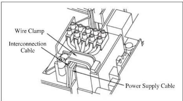
- The connecting wires to the indoor unit must be clamped on the wire clamps as shown in the figure.
- The power supply cord must be equivalent to H07RN-F which is the minimum requirement, and to be used in protective tube.
text_image
Wire Clamp Interconnection Cable Power Supply Cable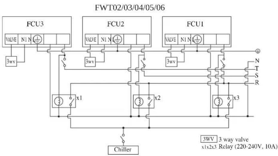
flowchart
graph TD
    subgraph FWT02/03/04/05/06
        A["FCU3"] --> B["VALVE N1 N"]
        B --> C["3wV"]
        D["FCU2"] --> E["VALVE N1 N"]
        E --> F["3wV"]
        G["FCU1"] --> H["VALVE N1 N"]
        H --> I["3wV"]
        J["x1"] --> K["x2"]
        L["x3"] --> M["x3"]
        K --> N["Chiller"]
        L --> O["Chiller"]
        P["3WV 3 way valve x1x2x3 Relay (220-240V, 10A)"] --> Q["+"]
        R["N"] --> S["T"]
        T["S"] --> U["R"]
    end
INDICATOR LIGHTS
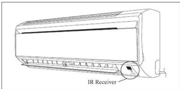
IR Signal Receiver
When an infrared remote control operating signal has been transmitted, the signal receiver on the indoor unit will respond as below to confirm acceptance of the signal transmission.
| ON to OFF 1 Long Beep | |
| OFF to ON Pump down/Cool force on | 2 Short Beep |
| Others 1 Short Beep |
Cooling Unit/Heat Pump Unit
The table shows the LED indicator lights for the air conditioner unit under normal operation and fault conditions.
The LED indicator lights are located at the right bottom of the air conditioner unit.
text_image
IR ReceiverLED Indicator Lights for Cooling Unit/Heat Pump Unit
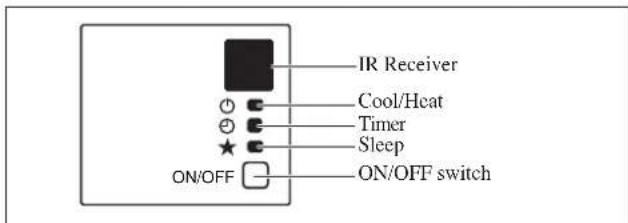
text_image
IR Receiver Cool/Heat Timer Sleep ON/OFF ON/OFF switchLED Indicator Lights: Normal Operation And Fault Conditions For Cooling/Heat Pump Unit
| COOL/HEAT(GREEN/RED) | Normal Operation/Fault Indication Action Error Code | ||||
| ○/● | ○Green | Cool mode - - | |||
| ○/● | ○Red | Heat mode - - | |||
| ○ | ○ | Timer on - - | |||
| ○ | ○ | Sleep mode on - - | |||
| ○ | Fan mode on - - | ||||
| ○ | Dry mode on | -- | |||
| 1 time | Room air sensor contactLoose/Short | Call your dealer | Blink E1 | ||
| ● | 2 times | Indoor coil sensor open/short | Call your dealer | Blink E2 | |
| 3 times | Pipe water temperature poor | - | Blink E4 | ||
| 1 time | Pipe water temperature bad | - | Blink E5 | ||
| 6 times | Hardware error (tact switch pin short) | Call your dealer | Blink E8 | ||
| ● | 4 times | No feedback from indoor fan | Call your dealer | Blink E9 |
AIR CONDITIONER UNIT OPERATION
Dry Mode
- When the air humidity is high, the unit can operate in dry mode. Press
button and choose . - If the room temperature is 2^ C/3.6°F higher than the set temperature, the air conditioner will operate under cooling mode until it reaches within the 2^ C/3.6°F range of difference compared to the set temperature before it converts to dry mode.
- If the room temperature is within the 2^ C/3.6°F range of difference compared to the set temperature, it will directly operate under dry mode.
- The unit will operate at LOW speed under dry mode.
Heat Mode (for heat pump unit only)
- When the unit at cold draft setting, the indoor fan will start to operate only after the coil reaches the desired temperature.
- For fan mode setting, indoor fan will continuous running once unit ON.
- When the set temperature is achieved, the indoor fan will operate until the coil cannot provide anymore additional heat.
Air Flow Control
- For more effective air circulation, you can manually adjust the air discharge grille to the left or right.
- During cool mode operation and dry mode operation, do not direct the air discharge louver downwards for too long. If operating continues in this way, condensation may occur on the louver, thus resulting in drippings.
Fan Speed And Rated Cooling Capacity
- The rated cooling capacity is provided at the HIGH fan speed.
- The cooling capacity is lower when the unit is operating at MEDIUM and LOW fan speed.
Notes On Flaps And Louvers Angles
- When "SWING button" is selected, the flaps swinging range depends on the operation mode. (See the figure.)
ATTENTION
- Always use a remote controller to adjust the flaps angle. If you attempt to move it forcibly with hand when it is swinging, the mechanism may be broken.
- Be careful when adjusting the louvers. Inside the air outlet, a fan is rotating at a high speed.
In COOL, DRY and FAN mode
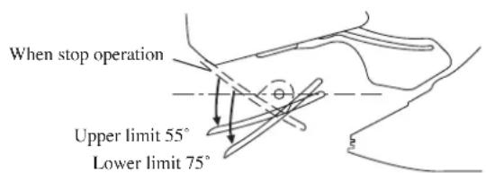
text_image
When stop operation Upper limit 55° Lower limit 75°In HEAT mode
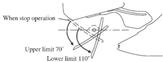
text_image
When stop operation Upper limit 70° Lower limit 110°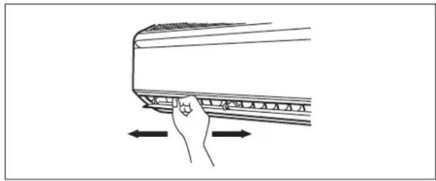
natural_image
Line drawing of a hand pressing down on a curved surface with directional arrows indicating movement (no text or symbols)OPERATING RANGE
Operating Limits:
Thermal carrier : Water
Water temperature : 4-10°C Cooling; 35-50°C Heating
Maximum water pressure : 16 bar
Air temperature : (as below)
Cooling Mode
| Temperature Ts °C/°F | Th °C/°F | |
| Minimum indoor temperature | 19.0 / 66.2 14.0 | / 57.2 |
| Maximum indoor temperature | 32.0 / 89.6 23.0 | / 73.4 |
Heating Mode
| Temperature Ts °C/°F | Th °C/°F | |
| Minimum indoor temperature | 15.0 / 59.0 - | |
| Maximum indoor temperature | 27.0 / 80.6 - |
Ts: Dry bulb temperature. Th: Wet bulb temperature.
AIR FILTER
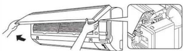
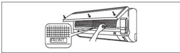
1. Open the front panel.
- Hold the panel at the recesses on the main unit (2 recesses on right and left sides) and lift it until it stops.
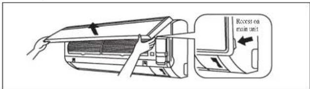
text_image
Recess on main unit2. Pull out the air filters.
- Push a little upwards the tab at the center of each air filter, then pull it down.
3. Clean or replace each filter.
- When shaking off remaining water, do not wring the filter.
4. Set the air filter as they were and close the front panel.
- Insert claws of the filters into slots of the front panel. Close the front panel slowly and push the panel at the 3 points. (1 on each side and 1 in the middle.)
- The air filter have a symmetrical form in the horizontal direction.
text_image
FRONTSERVICE AND MAINTENANCE
Note is valid for Turkey only: The lifetime of our products is ten (10) years
| Service Parts Maintenance Procedures | |
| Indoor air filter | Remove any dust adhering to the filter by using a vacuum cleaner or wash in lukewarm water (below 40°C/104°F) with a neutral cleaning detergent.Rinse the filter well and dry before placing it back onto the unit.Do not use gasoline, volatile substances or chemicals to clean the filter. |
| Indoor unit | Clean any dirt or dust on the grille or panel by wiping it with a soft cloth soaked in lukewarm water (below 40°C/104°F) and a neutral detergent solution.Do not use gasoline, volatile substances or chemicals to clean the indoor unit. |

CAUTION
- Avoid direct contact of any coil treatment cleaners on plastic part. This may cause plastic part to deform as a result of chemical reaction.
1. Open the front panel.
- Hold the panel at the recesses on the main unit (2 recesses on right and left sides) and lift it until it stops.
2. Remove the front panel.
- While lifting the front panel further, slide it to the right and pull it to the front side. The left rotating shaft is detached. Slide the right rotating shaft to the left and pull it to the front side to remove it.
3. Attach the front panel.
- Align the right and left rotating shafts of the front panel with the grooves and push them all the way in.
- Gently close the front panel. (Push both ends and the center on the front panel.)
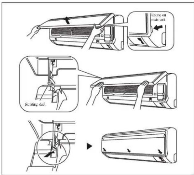
text_image
Recess on main unit Rotating shaft
CAUTION
- Don't touch the metal parts of the indoor unit. It may cause an injury.
- When removing or attaching the front panel, support the panel securely with hand to prevent it from falling.
- For cleansing, do not use hot water above 40^ C, benzine, gasoline, thinner, nor other volatile oils, polishing compound, scrubbing brushes, nor other hand stuff.
• After cleaning, make sure that the front panel is securely fixed.
When The Unit Is Not To Be Used For An Extended Long Period Of Time
| Operate the unit for 2 hours with the following setting.Operating mode : coolTemperature : 30°C/86°F | 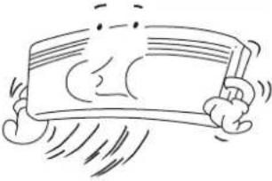 | Remove the power plug.If you are using an independent electric circuit for your unit, cut off the circuit.Remove the batteries in the remote control. | 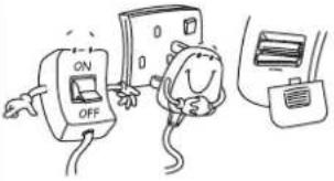 |
TROUBLESHOOTING
For any enquiries on spare part please contact your authorized dealer. When any malfunction of the air conditioner unit is noted, immediately switch off the power supply to the unit. Check the following fault conditions and causes for some simple troubleshooting tips.
| Fault Causes / Action | |
| The air conditioner unit does not operate.1. Power failure, or the fuse needs to be replaced.- The power plug is disconnected.- It is possible that your delay timer has been set incorrectly.- If the fault persist after all these verifications, please contact the air conditioner unit installer. | |
| The air flow is too low.2. The air filter is dirty. | - - The doors or windows are open.- The air suction and discharge are clogged.- The regulated temperature is not high enough. |
| Discharge air flow has bad odour.3. Odours may be caused by cigarettes, smoke particles, perfume etc. which might have adhered onto the coil. | |
| 4. Condensation on the front air grille of the indoor unit. | - This is caused by air humidity after an extended long period of operation.- The set temperature is too low, increase the temperature setting and operate the unit at high fan speed. |
| 5. Water flowing out from the air conditioner unit. | - Switch off unit and call dealer. |
If the fault persists, please call your local dealer / serviceman.
Information requirements for fan coil units
| Information to identify the model(s) to which the information relates : FWT02CATNMV1, FWT02GATNMV1 | ||||||||
| Item Symbol Value Unit Item Symbol Value Unit | ||||||||
| Cooling capacity (sensible) P | rated, c | 1,85 kW | Total electric power input P | elec | 0,031 kW | |||
| Cooling capacity (latent) P | rated, c | 0,58 kW | Sound power level (per speed setting, if applicable) | LWA | 45,0 /41,0 /36,0 dB | |||
| Heating capacity | Prated, b | 3,22 kW | ||||||
| Contact details | DAIKIN EUROPE N.V.Zandvoordestraat 300, B-8400 Oostende, Belgium | |||||||
| Information to identify the model(s) to which the information relates : FWT03CATNMV1, FWT03GATNMV1 | ||||||||
| Item Symbol Value Unit Item Symbol Value Unit | ||||||||
| Cooling capacity (sensible) P | rated, c | 2,02 kW Total electric power input P | elec | 0,032 kW | ||||
| Cooling capacity (latent) P | rated, c | 0,68 kW | Sound power level (per speed setting, if applicable) | LWA | 48,0 /44,0 /39,0 dB | |||
| Heating capacity | Prated, b | 3,52 kW | ||||||
| Contact details | DAIKIN EUROPE N.V.Zandvoordestraat 300, B-8400 Oostende, Belgium | |||||||
| Information to identify the model(s) to which the information relates : FWT04CATNMV1, FWT04GATNMV1 | ||||||||
| Item Symbol Value Unit Item Symbol Value Unit | ||||||||
| Cooling capacity (sensible) P | rated, c | 2,64 kW | Total electric power input P | elec | 0,042 kW | |||
| Cooling capacity (latent) P | rated, c | 0,67 kW | Sound power level (per speed setting, if applicable) | LWA | 55,0 /50,0 /45,0 dB | |||
| Heating capacity | Prated, h | 4,40 kW | ||||||
| Contact details | DAIKIN EUROPE N.V.Zandvoordestraat 300, B-8400 Oostende, Belgium | |||||||
| Information to identify the model(s) to which the information relates : FWT05CATNMV1, FWT05GATNMV1 | ||||||||
| Item Symbol Value Unit Item Sym | mbol Value Unit | |||||||
| Cooling capacity (sensible) P | rated, c | 3,43 kW | Total electric power input P | elec | 0,057 kW | |||
| Cooling capacity (latent) P | rated, c | 1,11 kW | Sound power level (per speed setting, if applicable) | LWA | 55,0 /51,0 /47,0 dB | |||
| Heating capacity | Prated, b | 6,01 kW | ||||||
| Contact details | DAIKIN EUROPE N.V.Zandvoordestraat 300, B-8400 Oostende, Belgium | |||||||
| Information to identify the model(s) to which the information relates : FWT06CATNMV1, FWT06GATNMV1 | ||||||||
| Item Symbol Value Unit Item Symbol Value Unit | ||||||||
| Cooling capacity (sensible) P | rated, c | 4,10 | kW Total | electric power input P | elec | 0,072 kW | ||
| Cooling capacity (latent) P | rated, c | 1,18 kW | Sound power level (per speed setting, if applicable) | LWA | 59,0 /54,0 /51,0 dB | |||
| Heating capacity | Prated, b | 7,33 kW | ||||||
| Contact details | DAIKIN EUROPE N.V.Zandvoordestraat 300, B-8400 Oostende, Belgium | |||||||
MEMO
Innen-Gerät
natural_image
Diagram showing airflow or ventilation system inside a car air conditioner unit, with no visible text or symbolsnatural_image
Hand pressing down on a curved panel with directional arrows indicating compression or force (no text or symbols)BETRIEBSBEREICH
natural_image
Technical line drawing of a washing machine and its internal air vent (no text or symbols)⚠ VORSICHT
MANUEL D'INSTALLATION
natural_image
Diagram of a car air conditioner unit showing airflow path and internal components (no text or labels)natural_image
Hand holding a curved panel with directional arrows indicating movement or force (no text or symbols)PLAGE D'EXPLOITATION
INSTALLATIE PLAAT FWT02/03/04
| Model\Afmeting | A | B | C | D | E | F | G | H | I | J | K | L | |
| FWT02/03/04 800 288 | 206 10 | 4 141 | 30 46 5 | 5 56 15 | 3 181 | 207 52 |
INSTALLATIEPLAAT FWT05/06
| Model\Afmeting | A | B | C | D | E | F | G | H | I | J | K | L | |
| FWT05/06 1065 310 224 190 | 173 61 | 40 45 | 48 91 2 | 19 580 | 45 |
⚠ WAARSCHUWING ⚠ LET
INSTALLATIE VAN DE BINNEN-UNIT
text_image
Diagram showing airflow or ventilation process of an air conditioner with labeled components and directional arrowsnatural_image
Line drawing of a hand pressing down on a curved panel with directional arrows (no text or symbols)WERKINGSBEREIK
natural_image
Diagram showing airflow or ventilation system inside a car, with no visible text or symbolsnatural_image
Hand holding a curved panel with directional arrows indicating movement or force (no text or symbols)natural_image
Diagram showing airflow or ventilation system inside a car, with no visible text or symbolsnatural_image
Illustration of a hand pressing down on a curved panel with directional arrows indicating movement (no text or symbols)natural_image
Diagram of a car air conditioner unit showing airflow path and internal components (no text or labels)natural_image
Illustration of a hand pressing down on a curved panel with directional arrows indicating movement (no text or symbols)ΦΑΣΜΑ ΛΕΙΤΟΥΡΓΙΑΣ
'Ορια λειτουργίας:
natural_image
Diagram of a car air conditioner unit showing airflow path and internal components (no text or symbols)Hand indoor unit's hook here.
natural_image
Illustration of a hand pressing down on a curved panel with directional arrows indicating movement (no text or symbols)FAIXA DE OPERAÇÃO
Limites operacionais:
natural_image
Diagram showing airflow or ventilation system inside a car, with no visible text or symbolsnatural_image
Hand pressing down on a curved surface with directional arrows indicating movement (no text or symbols)РАБОЧИЙ ДИАПАЗОН
natural_image
Diagram showing airflow or ventilation system inside a car, with no visible text or symbolsnatural_image
Line drawing of a hand pressing down on a curved panel with directional arrows indicating movement (no text or symbols)ÇALIŞMA ARALIĞI
natural_image
Technical line drawing showing a mechanical component before and after installation, with no visible text or symbols.
DİKKAT
Issue Date: 26 June 2019
DAIKIN MALAYSIA SDN. BHD
General Manager
Tamil Penindusthan Bukit Kaniman Putra, 47000 Sungai Buloh, Selangor Darul Ehsan, Malaysia.

WM-JW V2
- In the event that there is any conflict in the interpretation of this manual and any translation of the same in any language, the English version of this manual shall prevail.
- The manufacturer reserves the right to revise any of the specification and design contain herein at any time without prior notification.
- Im Falle einer widersprüchlichen Auslegung der vorliegenden Anleitung bzw. einer ihrer Übersetzungen gilt die Ausführung in Englisch.
- Änderungen von Design und technischen Merkmalen der in dieser Anleitung beschriebenen Geräte bleiben dem Hersteller jederzeit vorbehalten.
- En cas de désaccord sur l'interprétation de ce manuel ou une de ses traductions, la version anglaise fera autorité.
- Le fabriquant se réserve le droit de modifier à tout moment et sans préavis la conception et les caractéristiques techniques des appareils présentés dans ce manuel.
- In het geval dat een versie van deze handleiding in vertaling anders kan worden geïnterpreteerd dan de Engelse versie, geldt de Engelse versie.
- De fabrikant behoudt zich het recht voor specificaties en ontwerpkenmerken die in dezes worden vermeld, te allen tijde te herzien zonder voorafgaande kennisgeving.
- En caso de conflicto en la interpretación de este manual, y en su traducción a cualquier idioma, prevalecerá la versión inglesa.
- El fabricante se reserva el derecho a modificar cualquiera de las especificaciones y diseños contenidos en el presente manual en cualquier momento y sin notificación previa.
- Nel caso ci fossero conflitti nell'interpretazione di questo manuale o delle sue stesse traduzioni in altre lingue, la versione in lingua inglese prevale.
- Il fabbricante mantiene il diritto di cambiare qualsiasi specificazione e disegno contenuti qui senza precedente notifica.
- Σε περίπτωση διαφορών μεταξύ του εγχειριδίου αυτού και τυχόν μετάφρασής του σε οποιαδήποτε γλώσσα, υπερισχύει η Άγγλική έκδοση αυτού του εγχειριδίου.
- Ο κατασκευαστής διατηρεί το δικαίωμα αναθεώρησης των προδιαγραφών και σχεδίων που περιέχονται στο παρόν οποιαδήποτε στιγμή χωρίς προηγούμενη ειδοποίηση.
- A versão em inglês do Manual prevalecerá na eventualidade de qualquer conflito na interpretação deste Manual e de qualquer tradução do mesmo.
- O fabricante reserva-se o direito de rever qualquer uma das especificações e concepção/design aqui contido a qualquer altura sem aviso prévio.
- В случае противоречия перевода данного руководства с другими переводами одного и того же текста, английский вариант рассматривается как приоритетный.
- Завод-изготовитель оставляет за собой право изменять характеристики и конструкцию в любое время без предварительного уведомления.
- Bu kılavuzun anlaşılmasında bir çatışma olduğunda ve farklı dillerdeki tercümeler farklılık gösterdiğinde, bu kılavuzun ingilizce sürümü üstün tutulacaktır.
- Üretici burada bulunan teknik özellikleri ve tasarımları herhangi bir zamanda ve önceden haber vermeden değiştirme hakkını saklı tutar.
DAIKIN EUROPE N.V.
P.O.Box 18674, Jebel Ali Free Zone, Dubai-UAE
Email: info@daikinmea.com
Web: www.daikinmea.com
Importer for Turkey
DAIKIN ISITMA ve SOĞUTMA SISTEMLERI SAN TIC A.Ş.
Allianz Plaza-Kucukbakkalkoy Mah.Kayısdagi Cad.No:1 34750 Atasehir-ISTANBUL / TURKIYE
DAIKIN INDUSTRIES, LTD.
Head office:
Umeda Center Bldg., 2-4-12, Nakazaki-Nishi, Kita-ku, Osaka, 530-8323 Japan
Tokyo offi ce:
JR Shinagawa East Bldg., 2-18-1, Konan,
Minato-ku, Tokyo, 108-0075 Japan
http://www.daikin.com/global/
DAIKIN MALAYSIA SDN. BHD.
Lot 60334, Persiaran Bukit Rahman Putra 3, Taman Perindustrian Bukit Rahman Putra, 47000 Sungai Buloh, Selangor Darul Ehsan, Malaysia.
JR Shinagawa East Bldg., 2-18-1, Konan,
Minato-ku, Tokyo, 108-0075 Japan
http://www.daikin.com/global/
DAIKIN MALAYSIA SDN. BHD.
Lot 60334, Persiaran Bukit Rahman Putra 3,
Taman Perindustrian Bukit Rahman Putra,
47000 Sungai Buloh, Selangor Darul Ehsan,
Malaysia.
DAIKIN EUROPE N.V.
P.O.Box 18674, Jebel Ali Free Zone, Dubai-UAE
Email: info@daikinmea.com
Web: www.daikinmea.com
Importer for Turkey
DAIKIN ISITMA ve SOĞUTMA SISTEMLERI SAN TIC A.Ş.
Allianz Plaza-Kucukbakkalkoy Mah.Kayısdagi Cad.No:1 34750
Atasehir-ISTANBUL / TURKIYE
مذكرة
مذكرة