DEH1080C - Dehumidifier MSW - Free user manual and instructions
Find the device manual for free DEH1080C MSW in PDF.

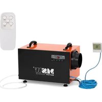
| Product Type | Dehumidifier |
| Brand | MSW |
| Model | DEH1080C |
| Dimensions (W x D x H) | 530 x 450 x 750 mm |
| Weight | 32 kg |
| Power Supply | 230 V / 50 Hz |
| Nominal Power | 545 W (27°C, 60% RH) |
| Max Power | 650 W (30°C, 80% RH) |
| Nominal Current | 2.7 A (27°C, 60% RH) |
| Dehumidification Capacity | 51 L/24h (30°C, 80% RH) / 28.7 L/24h (27°C, 60% RH) |
| Water Tank | 5.69 L |
| Refrigerant | R290 (230 g) |
| Application Area | 50 to 80 m² |
| Operating Temperature | 5 to 38 °C |
| Airflow Rate | 596 m³/h |
| Noise Level | ≤ 52 dB(A) |
| Timer | Yes (1-24 h) |
| Defrost Function | Automatic |
| IP Protection Rating | IPX0 |
| Internal Drying Function | Yes |
| Filter Maintenance | Clean every 6 weeks |
| Max. Allowable Pressure | 3.2 MPa (heat exchanger) |
| Transport | Vertical only |
Frequently Asked Questions - DEH1080C MSW
User questions about DEH1080C MSW
0 question about this device. Answer the ones you know or ask your own.
Ask a new question about this device
Download the instructions for your Dehumidifier in PDF format for free! Find your manual DEH1080C - MSW and take your electronic device back in hand. On this page are published all the documents necessary for the use of your device. DEH1080C by MSW.
USER MANUAL DEH1080C MSW
MSW-DEH1080A (MSAMnDEh)1080C MSW-DEH2000C

A. Aufsatz
B. Behälter
C. Schnecke
D. Rad
E. Griff
F. Filter
G. Zwischenlage
natural_image
Line drawing of a portable air purifier with a small case beside it, showing no text or symbols.
This User Manual has been translated using machine translation. We have made every effort to ensure the translation is accurate, but please note that automated translations are not perfect and are not meant to replace human translators. The official version of the User Manual is in English. Any differences between the translated version and the original English are not legally binding. If you have any questions about the accuracy of the translation, please refer to the English version, which is the official reference. More language versions are available upon request via info@expondo.com.
Technical data
| Parameter description | Parameter value | |||
| Product name Air dehumidifier | ||||
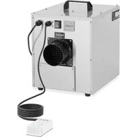
| Model | MSW-DEH1080A | MSW-DEH580B | MSW-DEH1080C | MSW-DEH2000C |
| Dehumidifying capacity [L/24h] | 43.251 (30°C, 80%RH)28.7 (27°C, 60%RH) | 3551 (30°C, 80%RH)28.7 (27°C, 60%RH) | 43.251 (30°C, 80%RH)28.7 (27°C, 60%RH) | 43.251 (30°C, 80%RH)28.7 (27°C, 60%RH) |
| Rated voltage [V~] / Frequency [Hz] | 230 / 50 | |||
| Rated input power [W] 545 (27°C, 60%RH) | ||||
| Rated input current [A] 2.7 (27°C, 60%RH) | ||||
| Max rated input power [W] | 650 (30°C, 80%RH) | |||
| Max rated input current [A] 3.1 (30°C, 80%RH) | ||||
| Protection class | I | |||
| Protection rating IP | IPXO | |||
| Dimensions [mm] | 530x450x750 | 3340x390x850 | 650x430x900 | 650x430x850 |
| Weight [kg] | 32 | 30 | 32 | |
| Water reservoir capacity [L] | 5.69 | |||
| Refrigerant type/amount [g] | R290/230 | |||
| Area of application [ m^2 ] | 50-80 | 50-70 | 50-80 | 50-70 |
| Application temperature [°C] | 5-38 | |||
| Air circulation speed [ m^3/h ] | 596 | 570 | 596 | 560 |
| Timer | √ | √ | √ | √ |
| Defrost function | √ | √ | √ | √ |
| Acoustic pressure level LpA [dB(A)] | ≤52 | |||
| Maximum suction/exhaust side working pressure [MPa] | 3.2/0.7 | |||
| Heat exchanger maximum allowable pressure [MPa] | 3.2 | |||
1. General description
The user manual is designed to assist in the safe and trouble-free use of the device. The product is designed and manufactured in accordance with strict technical guidelines, using state-of-the-art technologies and components. Additionally, it is produced in compliance with the most stringent quality standards.
DO NOT USE THE DEVICE UNLESS YOU HAVE THOROUGHLY READ AND UNDERSTOOD THIS USER MANUAL.
To increase the product life of the device and to ensure trouble-free operation, use it in accordance with this user manual and regularly perform maintenance tasks. The technical data and specifications in this user manual are up to date. The manufacturer reserves the right to make changes associated with quality improvement. The device is designed to reduce noise emission risks to a minimum, taking into account technological progress and noise reduction opportunities.
Legend

The product satisfies the relevant safety standards.

Read instructions before use.

The product must be recycled.

WARNING! or CAUTION! or REMEMBER! Applicable to the given situation.
(general warning sign)

ATTENTION! Electric shock warning!

ATTENTION! Fire hazard - flammable materials!

ATTENTION! Hot surface, risk of burns!

Only use indoors.

PLEASE NOTE! Drawings in this manual are for illustration purposes only and in some details may differ from the actual product.
2. Usage safety

ATTENTION!
Read all safety warnings and all instructions. Failure to follow the warnings and instructions may result in electric shock, fire and/or serious injury or even death.
The terms "device" or "product" are used in the warnings and instructions to refer to:
Air dehumidifier
Do not use in the direct vicinity of water tanks. Prevent the device from getting wet. Risk of electric shock! Do not cover air inlets / outlets! Do not put your hands or other items inside the device while it is in use! Do not cover the ventilation openings!
2.1. Electrical safety
a) The plug must fit the socket. Do not modify the plug in any way. Using original plugs and matching sockets reduces the risk of electric shock.
b) Avoid touching earthed elements such as pipes, heaters, boilers and refrigerators. There is an increased risk of electric shock if the earthed device is exposed to rain, comes into direct contact with a wet surface or is operating in a damp environment. Water getting into the device increases the risk of damage to the device and of electric shock.
c) Do not touch the device with wet or damp hands.
d) Use the cable only for its designated use. Never use it to carry the device or to pull the plug out of a socket. Keep the cable away from heat sources, oil, sharp edges or moving parts. Damaged or tangled cables increase the risk of electric shock.
e) Do not use the device if the power cord is damaged or shows obvious signs of wear. A damaged power cord should be replaced by a qualified electrician or the manufacturer's service centre.
f) To avoid electric shock, do not immerse the cord, plug or device in water or other liquids. Do not use the device on wet surfaces.
g) ATTENTION! DANGER TO LIFE! While cleaning, never immerse the device in water or other liquids.
2.2. Safety in the workplace
a) Make sure the workplace is clean and well lit. A messy or poorly lit workplace may lead to accidents. Try to think ahead, observe what is going on and use common sense when working with the device.
b) Do not use the device in a potentially explosive environment, for example in the presence of flammable liquids, gases or dust. The device generates sparks which may ignite dust or fumes.
c) If you discover damage or irregular operation, immediately switch the device off and report it to a supervisor without delay.
d) If there are any doubts as to the correct operation of the device, contact the manufacturer's support service.
e) Only the manufacturer's service point may repair the device. Do not attempt any repairs independently!
f) In case of fire, use a powder or carbon dioxide (CO2) fire extinguisher (one intended for use on live electrical devices) to put it out.
g) Children or unauthorised persons are forbidden to enter a work station. (A distraction may result in loss of control over the device).
h) Use the device in a well-ventilated space.
i) Regularly inspect the condition of the safety labels. If the labels are illegible, they must be replaced.
j) Please keep this manual available for future reference. If this device is passed on to a third party, the manual must be passed on with it.
k) Keep packaging elements and small assembly parts in a place not available to children.
I) Keep the device away from children and animals.
m) If this device is used together with another equipment, the remaining instructions for use shall also be followed.

Remember! When using the device, protect children and other bystanders.
2.3. Personal safety
a) Do not use the device when tired, ill or under the influence of alcohol, narcotics or medication which can significantly impair the ability to operate the device.
b) The device is not designed to be handled by persons (including children) with limited mental and sensory functions or persons lacking relevant experience and/or knowledge unless they are supervised by a person responsible for their safety or they have received instruction on how to operate the device.
c) The device can be handled only by physically fit persons who are capable of handling it, properly trained, familiar with this manual and trained within the scope of occupational health and safety.
d) When working with the device, use common sense and stay alert. Temporary loss of concentration while using the device may lead to serious injuries.
e) To prevent the device from accidentally switching on, make sure the switch is on the OFF position before connecting to a power source.
f) The device is not a toy. Children must be supervised to ensure that they do not play with the device.
g) The device contains a flammable gas (R290) – it should be stored in a well-ventilated place, where there is no open fire or gas appliances and electric heaters in use!
2.4. Safe device use
a) Do not overload the device. Use the appropriate tools for the given task. A correctly-selected device will perform the task for which it was designed better and in a safer manner.
b) Do not use the device if the "ON/OFF" switch does not function properly (does not switch the device on and off). Devices which cannot be switched on and off using the "ON/OFF" switch are hazardous, should not be operated and must be repaired.
c) Disconnect the device from the power supply before commencement of adjustment, cleaning and maintenance. Such a preventive measure reduces the risk of accidental activation.
d) When not in use, store in a safe place, away from children and people not familiar with the device who have not read the user manual. The device may pose a hazard in the hands of inexperienced users.
e) Keep the device in perfect technical condition. Before each use check for general damage and especially check for cracked parts or elements and for any other conditions which may impact the safe operation of the device. If damage is discovered, hand over the device for repair before use.
f) Keep the device out of the reach of children.
g) Device repair or maintenance should be carried out by qualified persons, only using original spare parts. This will ensure safe use.
h) To ensure the operational integrity of the device, do not remove factory-fitted guards and do not loosen any screws.
i) When transporting and handling the device between the warehouse and the destination, observe the occupational health and safety principles for manual transport operations which apply in the country where the device will be used.
j) Do not touch articulated parts or accessories unless the device has been disconnected from the power source.
k) Do not move, adjust or rotate the device in the course of work.
I) Do not leave this appliance unattended while it is in use.
m) Clean the device regularly to prevent stubborn grime from accumulating.
n) Do not cover the air intake and outlet.
o) The device is not a toy. Cleaning and maintenance may not be carried out by children without supervision by an adult person.
p) Do not run the device when empty.
q) It is forbidden to interfere with the structure of the device in order to change its parameters or construction.
r) Keep the device away from sources of fire and heat.
s) If the device has been tipped more than 45^ , allow it to sit upright for at least 24 hours before use.
t) Inspection and maintenance of the refrigerant system must be carried out by a qualified person only.

ATTENTION! Despite the safe design of the device and its protective features, and despite the use of additional elements protecting the operator, there is still a slight risk of accident or injury when using the device. Stay alert and use common sense when using the device.
3. Use guidelines
The device is designed to dehumidify the air in a room, protecting it and objects inside against the negative effects of moisture.
The user is liable for any damage resulting from unintended use of the device.
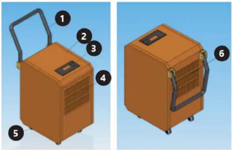
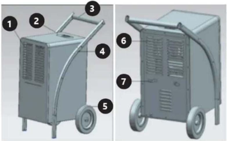
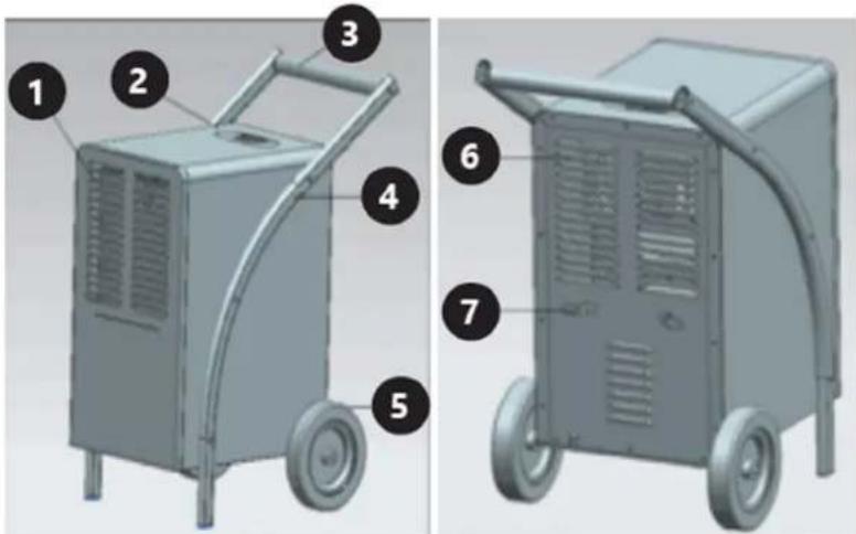
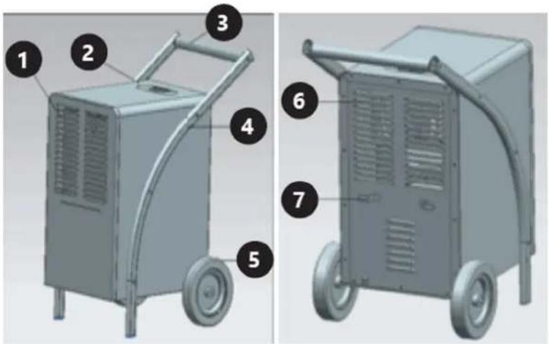
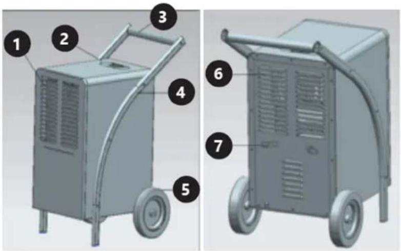
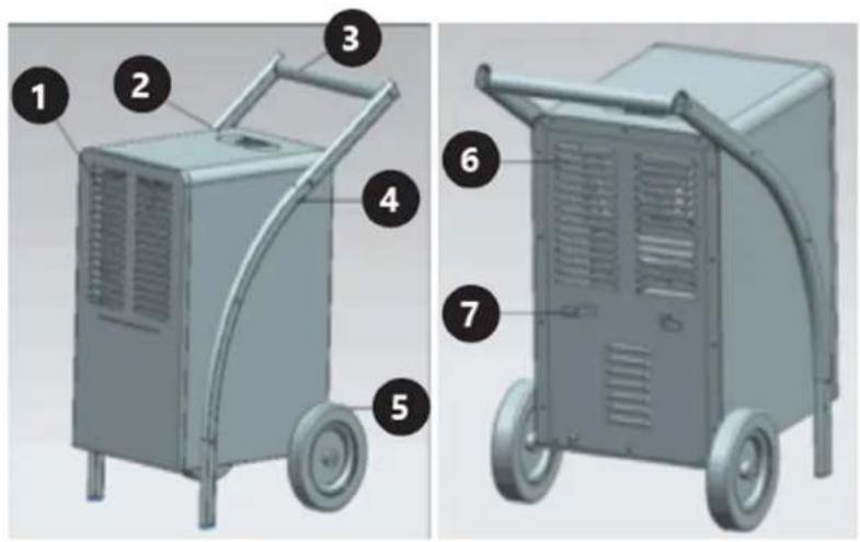
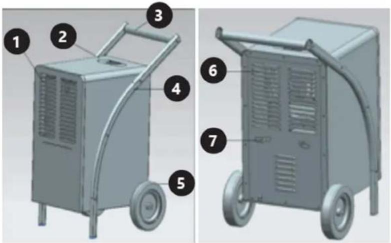
3.1. Device description
MSW-DEH1080A (MSW-DEH)1080C MSW-DEH2000C

-
Air inlet openings
-
Control panel with a display
-
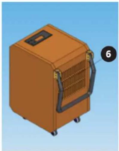
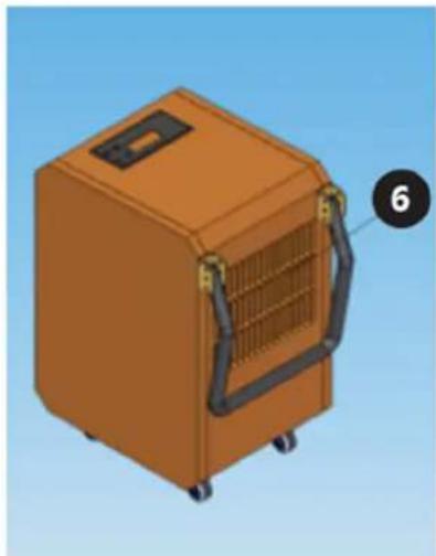
Carrying handle
-
Legs
-
Wheel (x2)
-
Air outlet openings
-
Mounting for a power cord
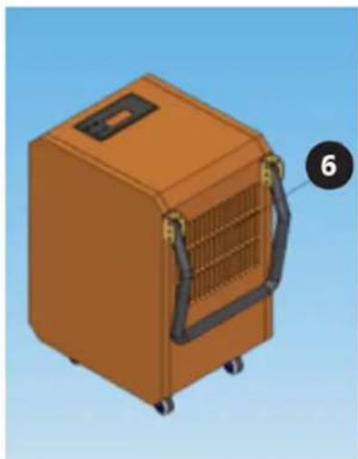
MSW-DEH580B
-
Carrying handle
-
Housing
-
Control panel with a display
-
Air inlet openings
-
Wheel (x4)
-
Air outlet openings
-
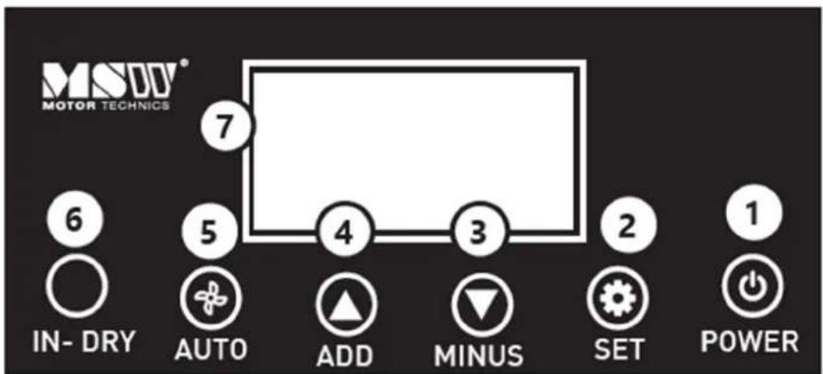
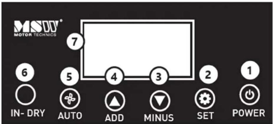
ON/OFF button
-
Timer on/off button
-
Value decreasing button
-
Value increasing button
-
ON/OFF button of continuous dehumidification
6. ON/OFF button of internal drying function
7. Display
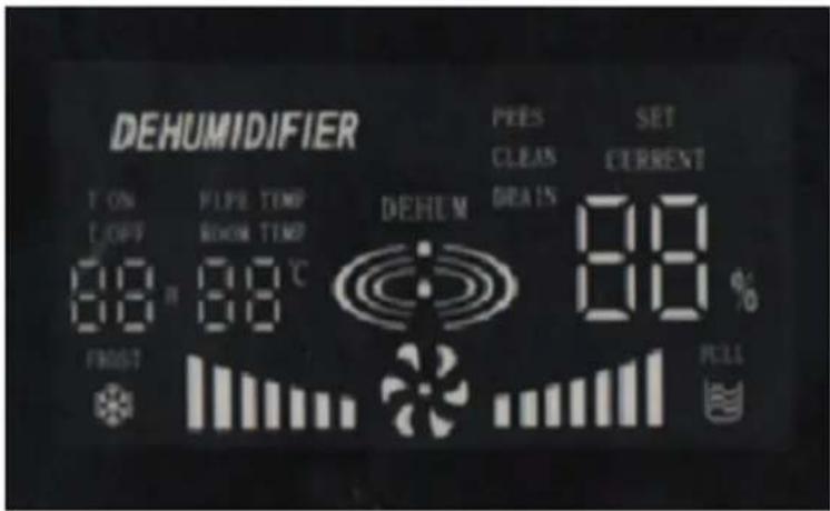
The display shows the following parameters:
• The current indoor air humidity CURRENT ...%
- Setting the target indoor air humidity SET ...%
- Cleaning indicator CLEAN
- Indicator for removing accumulated water: DRAIN
• Dryer operation with visual-signal
- Indoor temperature or of the pipes ... °C
PIPE TEMP ... °C
- Timer setting (time to turn the device on T ON / time to turn the device off T OFF; operation time ... H)
• Full reservoir indicator light
• Defrost indicator
3.2. Preparing for use
APPLIANCE LOCATION
The temperature of environment must not be higher than 38^ C and the relative humidity should be less than 95%. Ensure good ventilation in the room in which the device is being used. There should be at least 50 cm distance between each side of the device and the wall or other objects. The device should always be used when positioned on an even, stable, clean, fireproof and dry surface, and be out of the reach of children and persons with limited mental and sensory functions. Position the device such that you always have access to the power plug. The power cord connected to the appliance must be properly grounded and correspond to the technical details on the product label. Do not use or store the device in rooms smaller than 12 m^2 . If there are windows or doors in the room, they must be closed.
3.3. Assembling the device
THE EXAMPLE OF MSTWHDOTHERS ARE SIMILAR
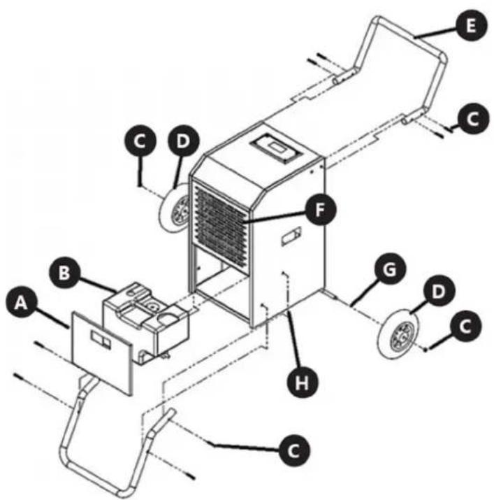
A. Cap
B. Tank
C. Screw
D. Wheel
E. Handle
F. Filter
G. Spacer
H. Hole for supporter
3.4. Device use
CAUTION: Each time a button is pressed on the control panel, an acoustic signal is emitted.
3.4.1 STARTING/STOPPING THE DEVICE AND CONTINUOUS OPERATION
Press the POWER button (1) on the control panel, the device will start and automatically start continuous drying. In this mode, it is not possible to set a target humidity level.
To turn the device off, press the same button (1) and the device will finish its operation after a short delay, i.e. until the fan stops.
CAUTION: In the event of a power drop or loss, the device has a built-in compressor protection that will restart the compressor with a 3-minute delay.
3.4.2 STANDARD DEVICE OPERATION
After turning the device on (see the point above), press the AUTO button (5) on the control panel – continuous operation will be turned off and the device will start working in the standard mode with the default humidity level (50 %).
3.4.3 SETTING A TARGET HUMIDITY LEVEL
With the device turned on, press the SET button (2) on the control panel to set a target room humidity during standard operating mode. By pressing the buttons for decreasing or increasing the parameter (3 or 4), set the target value in the range 20–90% – leave the selected value until it stops flashing on the display, which means that it has been saved. The device will then cycle automatically to maintain the set value.
3.4.4 TIMER SETTING
It is possible to set the operating time range of the device in hourly intervals from 1–24 hours.
- Automatic activation time – with the device turned off (but connected to the power source), press the SET button (2) on the control panel to activate the Timer, the T ON indicator lights up on the display, and then use the buttons for decreasing or increasing the parameter to set the number of hours after which devices are to start up automatically. Leave the amount set on the display until it blinks 4 times, then the time to start will be saved and the device will start counting down.
- Time operation cycle – with the device turned on, press the SET button (2) on the control panel to activate the Timer and then use the parameter decreasing or increasing buttons (3 or 4) to set the number of hours to turn off, T after confirmation as above, and then using the same buttons (3 or 4) to switch the device on again. After a given time has elapsed the device automatically turn off, and then after a certain time has elapsed from turning it off, it will turn on again and again according to the set time cycle OFF-ON-OFF-ON ...
Similarly to the above procedure, you can set the time operation cycle with the device turned off (connected to the power source). Press the SET button (2) on the control panel to start the Timer function, then use the parameter decreasing / increasing buttons (3 or 4) to set the time after which the device is to start automatically T ON, then confirm the time after which it is to stop working and turn off, i.e. switch to standby mode T OFF. The device will then start working according to the set time cycle ON-OFF-ON-OFF...
- Cancelling the Timer function – when working with the active Timer, press the SET button (2) on the control panel to disable the Timer function, but it does not turn off the device itself. An alternative method of deactivating the timer function is to turn the device off by pressing the POWER button (1) on the control panel, which also turns the device off itself.
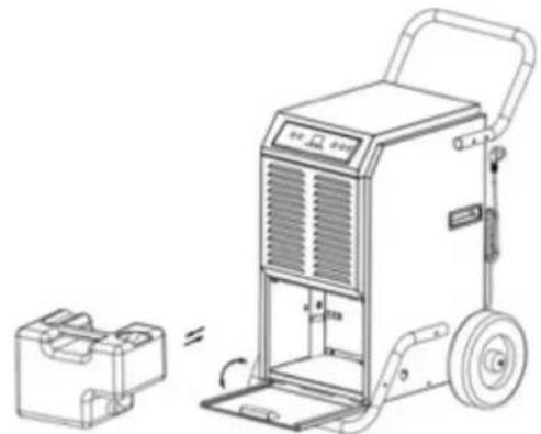
3.4.5 FULL RESERVOIR INDICATOR LIGHT
In the event of a full water reservoir, the device will automatically stop working and activate a continuous alarm informing about its fullness, additionally signalling this fact with an icon on the control panel (see the description of the display). Drain the water from the tank. To do this, first turn the device off with the POWER button (1), then open the front panel of the device and grasping the handle on the reservoir, slide it horizontally away from the device. After emptying it, reinstall it in the device in the reverse order of the removal. Press the POWER button (1) to restart the device.
natural_image
Line drawing of a portable air purifier with a box and wheels, showing no text or symbols.The icon of a full tank may also activate in case of its incorrect assembly – then its mounting should be improved and the device will restart automatically.
There is an alternative method of emptying the device of accumulated water: turn the device on with the POWER button (1), then open the front panel and remove the water tank. Put the hose of appropriate size (not included) through the drain hole at the base of the device and attach one of its ends to the special connection inside the tank compartment, taking care that the drain hose is not twisted or bent anywhere. Put the water tank back into the device and close the front panel.
3.4.6 INTERNAL DRYING FUNCTION
When the device is turned off, press the IN-DRY button (6) on the control panel. This function dries the inside of the device from the accumulated moisture, thus extending its life.
3.4.7 DEFROST FUNCTION
At low indoor temperatures, frost may build up on the evaporator, reducing the air flow during drying. In this case, the device will automatically start the defrost function – it will stop the compressor, and the fan will continue to work. Do not turn the device off during this time! Activation of this function will be signalled by the blinking of the appropriate indicator lamp on the display (see display description). After defrosting, the device will automatically go into the dehumidifying mode.
3.4.8 TROUBLESHOOTING
| PROBLEM | ACTIVITY/POSSIBLE REASON | SOLUTION | |
| The device doesn’t work | Is it properly connected to the power supply? | Check the connection. | |
| Check if the full tank indicator light is off on the display. | Drain the tank and reinstall it in the device or check if it is correctly mounted. | ||
| Check the ambient temperature. | The ambient working temperature should be in the range of 5–35°C. | ||
| Steam is slightly condensing | Check the air filter for debris. | Clean the air filter if necessary (see "Cleaning and maintenance"). | |
| Check if the air duct is not blocked. | Remove any foreign matter from the air duct. | ||
| Check if the indoor temperature is below 20°C. | Normal behavior – low humidity in a low temperature environment. | ||
| The set tar- get humidity is higher than the actual indoor humidity. | Set the target humidity level lower than it is indoor. | ||
| Water leak | Overflow when moving the device. | Drain the water tank before transport. | |
| Is the drain hose kinked or bent? | Correct the arrangement of the drain hose. | ||
| The device is excessively noisy | Is the device stable? | Place the device on an even and stable surface. | |
| Check for loose parts in the device? | Mount or secure these elements or contact the manufacturer's service department. | ||
| The noise sounds like flowing water. | The sound is made by circulating refrigerant and it is normal. | ||
| An error code is displayed | “E1” | Temperature sensor defective. | Check the connection or replace the sensor. |
| “E2” | Moisture sensor dirty or broken. | Clean or replace the sensor. | |
| “E3” | Indoor temperature sensor defective. | Check the connection or replace the sensor. | |
3.5. Cleaning and maintenance
a) Unplug the mains plug and allow the device to cool completely before each cleaning, adjustment or replacement of accessories, or if the device is not being used.
- Wait for the rotating elements to stop.
b) Use only non-corrosive cleaners to clean the surface.
c) Store the unit in a dry, cool place, free from moisture and direct exposure to sunlight.
d) Do not spray the device with a water jet or submerge it in water.
e) Do not allow water to get inside the device through vents in the housing of the device.
f) Clean the vents with a brush and compressed air.
g) The device must be regularly inspected to check its technical efficiency and spot any damage.
h) Use a soft cloth for cleaning.
i) Do not use sharp and/or metal objects for cleaning (e.g. a wire brush or a metal spatula) because they may damage the surface material of the appliance.
j) Do not clean the device with an acidic substance, agents of medical purposes, thinners, fuel, oils or other chemical substances because it may damage the device.
k) Inspection and replenishment of the refrigerant may only be performed by a specially qualified person and with the use of specialized equipment!
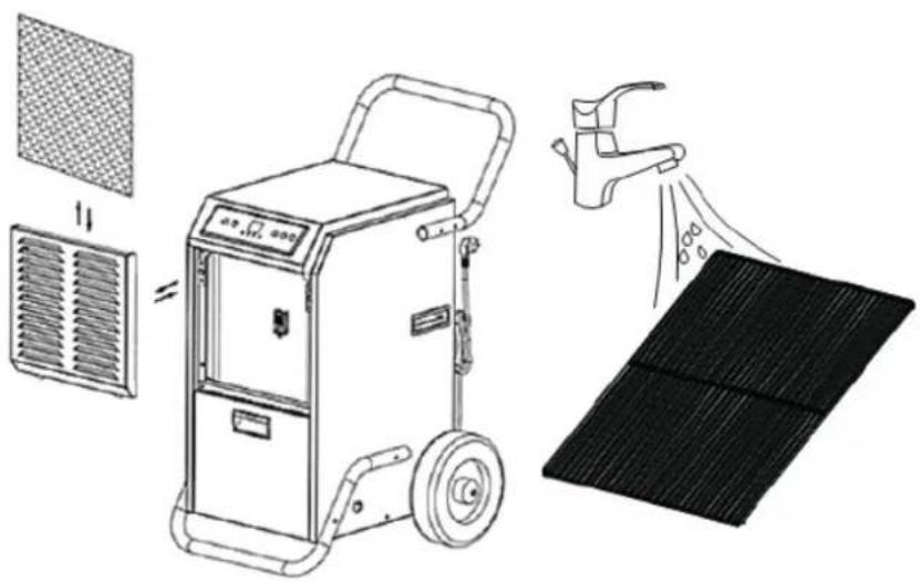
I) With regular use, clean the air filter every 6 weeks.
Turn the device off. The air filter is located at the front of the device – after removing or opening the front panel, remove the mesh filter. In the case of light dirt, remove the accumulated dirt on the mesh surface with a clean cloth. In the case of heavy contamination, also inside the filter screen, rinse the filter under a tap with running water and dry it completely before reinstalling it in the device.
natural_image
Illustration of a portable air purifier with cooling fan, air drain, and solar panel (no text or symbols)
CAUTION! Do not use the device without the air filter – it may pollute the evaporator! Do not touch
the evaporator surface with bare hands – the risk of injury!
DISPOSING OF USED DEVICES
Do not dispose of this device in municipal waste systems. Hand it over to an electric and electrical device recycling and collection point. Check the symbol on the product, instruction manual and packaging. The plastics used to construct the device can be recycled in accordance with their markings. By choosing to recycle you are making a significant contribution to the protection of our environment.
Contact local authorities for information on your local recycling facility.
TRANSPORTATION & STORAGE

WARNING!
Improper transportation of this device may cause damage that will result in a voided warranty.
- Transport the dehumidifier in an upright position. Incorrect positioning may lead to damage of internal components.
• Ensure the dehumidifier is secured against shocks and falls. - Avoid exposing the device to extreme temperatures or moisture during transportation.
- Do not remove factory-installed protections before the device reaches the installation site.
Any damage resulting from improper transportation will void the warranty.
a) Use the original packaging or equivalent protective materials during transportation.
b) Avoid excessive shocks or mechanical damage while handling the device.
c) Ensure the device is used in suitable conditions, including maintaining a minimum ambient temperature of 19 degrees Celsius for proper operation.
d) The device shall be installed, operated and stored in a room with a floor area larger than 15m².
e) Follow the instructions for setup, usage and storage.

MSW-DEH1080A(MSW-DEH1080C MSW-DEH2000C

A. Zakrętka
B. Zbiornik
C. Ślimak
D. Koło
E. Uchwyt
F. Filtr
G. Przekładka
natural_image
Technical line drawing of a portable air purifier with a smaller housing and control panel (no text or symbols)
MSW-DEH1080A (MSW-DEH1080C MSW-DEH2000C

A. Zátka
B. Nádržka
C. Šnek
D. Kolo
E. Držák
F. Filtr
G. Distanční vložka
H. Otvor pro podporovatele
natural_image
Line drawing of a portable air purifier with a small box nearby (no text or symbols)
MSW-DEH1080A (MSW-DEH)080C MSW-DEH2000C
A. Cache
B. Réservoir
C. Vis sans fin
D. Roue
E. Poignée
F. Filtre
G. Entretoise
natural_image
Line drawing of a portable air purifier with a small case beside it (no text or symbols)natural_image
Illustration of a portable air purifier with cooling fan, air drain, and solar panel (no text or symbols)
MSW-DEH1080A (MSW-DEH1080C MSW-DEH2000C

A. Cappuccio
B. Contenitore
C. Molla a lumaca
D. Ruota
E. Maniglia
F. Filtro
G. Distanziatore
natural_image
Technical line drawing of a portable air purifier with a smaller case and control panel (no text or symbols)
MSW-DEH1080A (MSW-DEH1080C MSW-DEH2000C

natural_image
Line drawing of a portable air purifier with a small case beside it, showing no text or symbols.
MSW-DEH1080A (MSW-DEH1080C MSW-DEH2000C

A. Rátét
B. Tartály
C. Csiga
D. Kerék
E. Fogantyú
F. Szúrő
G. Távtartó
natural_image
Technical line drawing of a portable air purifier with a side-view inset showing its internal components (no text or symbols)
MSW-DEH1080A (MSigh-DeH)080C MSW-DEH2000C
APPARATETS PLACERING
A. Hætte
B. Beholder
C. Snegl
D. Hjul
E. Händtag
F. Filter
G. Skive
natural_image
Line drawing of a portable air purifier with a small case beside it, showing no text or symbols.
MSW-DEH1080A (MSW-DEH1080C MSW-DEH2000C


natural_image
3D rendering of an orange industrial machine with attached ductwork and mounting feet (no text or symbols visible)A. Korkki
B. Tankki
C. Ruuvi
D. Pyörä
E. Kahva
F. Suodatin
G. Välikappale
natural_image
Line drawing of a portable air purifier with a small case beside it, showing no text or symbols.natural_image
Illustration of a portable electric heater with cooling panel and spray gun, showing internal components (no text or symbols)
MSW-DEH1080A (MSW-DEH1080C MSW-DEH2000C

PLAATS VAN HET APPARAAT
A. Pet
B. Tank
C. Skrue
D. Hjul
E. Handvat
F. Filter
G. Afstandhouder
natural_image
Line drawing of a portable air purifier with a small case beside it, showing no text or symbols.
OBS! Varm overflate, fare for forbrenning!

MSW-DEH1080A (MSW-DEH1080C MSW-DEH2000C
natural_image
3D rendering of an orange industrial device with attached pipes and a labeled part (6), against a blue background (no text or symbols on the device itself)A. Lokk
B. Tank
C. Skrue
D. Hjul
E. Håndtak
F. Filter
G. Avstandsstykke
H. Hull for supporter

OBS! Brandrisk - brandfarliga material!

MSW-DEH1080A (MSW-DEH1080C MSW-DEH2000C
APPARATENS PLACERING
A. Lock
B. Tank
C. Gängad bult
D. Hjul
E. Handtag
F. Filter
G. Spacer
natural_image
Line drawing of a portable air purifier with a small case beside it, showing no text or symbols.
MSW-DEH1080A (MSW-DEH1080C/MSW-DEH2000C s
e
m
e

-
Alça de transporte
-
Habitação
-
Painel de controle com display
-
Aberturas de entrada de ar
-
Roda (x4)
-
Aberturas de saída de ar
A. Boné
B. Tanque
C. Parafuso
D. Roda
E. Pega
F. Filtro
G. Espaçador
natural_image
Line drawing of a portable air purifier with a small case underneath (no text or symbols)
MSW-DEH1080A (MSW-DEH1080C MSW-DEH2000C


natural_image
3D rendering of an orange industrial machine with attached pipes and ventilation slots (no text or symbols visible)A. Čiapka
B. Nádrž
C. Skrutka
D. koleso
E. Rukovät
F. Filter
G. Rozperka
H. Otvor pre podporovatel'a
natural_image
Line drawing of a portable air purifier with a small case beside it (no text or symbols)
MSW-DEH1080A (MSW-DEH1080C/MSW-DEH2000C подобни)

- Дръжка за носене
2.Жилища
natural_image
Line drawing of a portable air purifier with a small case beside it, showing no text or symbols.
A. Καπάκι
B. Δεξαμενή
C. Bíδα
D. Τροχός
E. Λαβή
F. Φίλτρο
G. Αραιώνων
natural_image
Line drawing of a portable air purifier with a small case beside it, showing no text or symbols.
MSW-DEH1080A (MSW-DEH1080C/MSW-DEH2000C s
| i čno)

natural_image
3D rendering of an orange industrial machine with black handle and ventilation slots (no text or symbols)natural_image
Line drawing of a portable air purifier with a small box nearby (no text or symbols)Ikona punog spremnika također se može aktivirati u slučaju njegove neispravne montaže - tada treba poboljšati njegovu montažu i uređaj će se automatski ponovno pokrenuti.
Postoji alternativni način pražnjenja uređaja od nakupljene vode: uključite uređaj tipkom POWER (1), zatim otvorite prednju ploču i uklonite spremnik za vodu. Provucite crijevo odgovarajuće veličine (nije uključeno) kroz odvodni otvor na podnožju uređaja i spojite jedan njegov kraj na poseban priključak unutar odjeljka spremnika, pazeći da odvodno crijevo nigdje nije uvrnuto ili savijeno. Vratite spremnik za vodu u uređaj i zatvorite prednju ploču.
3.4.6 FUNKCIJA UNUTARNJEG SUŠENJA
Kada je uređaj isključen, pritisnite tipku IN-DRY (6) na upravljačkoj ploči. Ova funkcija isušuje unutrašnjost uređaja od nakupljene vlage i tako mu produljuje vijek trajanja.
3.4.7 FUNKCIJA ODMRZAVANJA

OPREZ! Nemojte koristiti uređaj bez zračnog filtra – može zagaditi isparivač! Ne dirajte površinu
MSW-DEH1080A (MSW-DEH1080C MSW-DEH2000C
natural_image
3D rendering of an orange industrial machine with attached ductwork and mounting feet (no text or symbols visible)A. Cap
B. Tankas
C. Varžtas
D. Ratas
E. Rankena
F. Filtruoti
G. Tarpiklis
H. Skylé rémèjui
natural_image
Line drawing of a portable air purifier with a small case beside it, showing no text or symbols.natural_image
Illustration of a portable air purifier with cooling fan, air drain, and solar panel (no text or symbols)
MSW-DEH1080A (MSW-DEH)1080C MSW-DEH2000C
A. Capac
B. Rezervor
C. Şurub
D. roată
E. Mâner
F. Filtra
G. Distanțiere
natural_image
Line drawing of a portable air purifier with a small box nearby (no text or symbols)MSW-DEH1080A (MSW-DEH1080C MSW-DEH2000C

A. kapa
B. Rezervoar
C. Vijak
D. kolo
E. Ročaj
F. Filter
G. Distančnik
H. Luknja za nosilec
3.4. Uporaba naprave
natural_image
Line drawing of a portable air purifier with a side view showing its open lid and wheels (no text or symbols)natural_image
Illustration of a portable electric heater with cooling panel and spray gun, showing internal components (no text or symbols)
For the disposal of the device please consider and act according to the national and local rules and regulations.
CONTACT
expondo Polska sp. z o.o. sp. k.