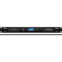
IPX 4800 - Receiver Lab Gruppen - Free user manual and instructions
Find the device manual for free IPX 4800 Lab Gruppen in PDF.


| Product type | Power amplifier with integrated DSP (receiver category) |
| Brand | Lab Gruppen |
| Model | IPX 4800 |
| Depth (rack) | 472 mm (from rack brackets to rear panel) |
| Weight | 8.4 kg |
| Power supply | Universal 100-240 V, 50/60 Hz |
| Inputs | Analog XLR (2 channels), AES3 digital XLR, with Link outputs |
| Outputs | Terminal blocks and Neutrik speakON (4-pole for channel 1+2, 2-pole for channel 2) |
| DSP functions | Filter, parametric EQ (up to 10 bands), delay (up to 2 s), limiter, input mixing/routing |
| Network control | Ethernet (RJ45) with shielded Cat-5 cable or WiFi via external router, IPX Controller software and iPad app |
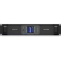
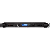
| Display | Backlit screen with MENU, BACK, MUTE buttons and ADJUST/SET encoder |
| LED indicators | POWER (red standby), SIG (green signal, red clipping), LIM (limiter active) |
| Safety | Do not open the device, use only professional cables, disconnect during thunderstorms, mandatory grounding |
| Cleaning | With a dry cloth only |
| Operating temperature | 5°C to 45°C |
| Fuse | Replace only with a model of the same size and same electrical rating |
| Warranty | Limited warranty - see community.musictribe.com/support |
Frequently Asked Questions - IPX 4800 Lab Gruppen
User questions about IPX 4800 Lab Gruppen
0 question about this device. Answer the ones you know or ask your own.
Ask a new question about this device
Download the instructions for your Receiver in PDF format for free! Find your manual IPX 4800 - Lab Gruppen and take your electronic device back in hand. On this page are published all the documents necessary for the use of your device. IPX 4800 by Lab Gruppen.
USER MANUAL IPX 4800 Lab Gruppen
Compact 4800, 2400 and 1200 Watt 2-Channel DSP Controlled Power Amplifiers
2 IPX Series Quick Start Guide 3
EN
ES
FR
EN Important Safety Instructions

Terminals marked with this symbol carry electrical current of sufficient magnitude to contribute risk of electric shock. Use only high-quality professional speaker cables with 14" TS or twist-locking plugs pre-installed. All other installation or modification should be performed only by qualified personnel.
This symbol, wherever it appears, alerts you to the presence of uninsulated dangerous voltage inside the enclosure - voltage that may be sufficient to constitute a risk of shock. This symbol, wherever it appears, alerts you to important operating and maintenance instructions in the accompanying literature. Please read the manual.
Caution To reduce the risk of electric shock, do not remove the top cover (or the rear section). No user sentoeable parts inside. Refer servicing to qualified personnel.
Caution To reduce the risk of fire or electric shocks, do not expose this appliance to rain and moisture. The apparatus shall not be exposed to dripping or splashing liquids and no objects filled with liquids, such as vases, shall be placed on the apparatus.
Caution These service instructions are for use by qualified service personnel only. To reduce the risk of electric shock do not perform any servicing other than that contained in the operation instructions. Repairs have to be performed by qualified service personnel.
Warning Please refer to the information on the exterior of bottom enclosure for electrical and safety information before installing or operating the device.
- Please read and follow all instructions and warnings.
-
Keep the apparatus away from water (except for outdoor products).
-
Clean only with dry clodi.
-
Do not block ventilation openings. Do not install in a confined space. Install only according to manufacturer's instructions.
-
Protect the power card from damage, particularly at plugs and appliance socket.
-
Do not install near any heat sources such as radiators, heat registers, stoves or other apparatus (including amplifiers) that produce heat.
-
Do not defeat the safety purpose of the polarized or grounding-type plug. A polarized plug has two blades with one wider than the other (only for USA and Canada), if grounding type plug has two blades and a third grounding proing. The wide blade or the third proing are provided for your safety. If the provided plug does not fit into your outlet, consult an electrician for replacement of the chonnie outlet.
-
Protect the power cord from damage, particularly at plugs and appliance socket.
-
Use only attachments and accessories recommended by the manufacturer.

- Use only specified carts, stands, tripods, brackets, or tables. Use caution to present tip over when meeting the cart/ apparatus combination.
- Unplug during storms, or if not in use for
along period.
-
Only use qualified personnel for servicing, especially after damage.
-
The apparatus with protective earthing terminal shall be connected to a MAINS socket outlet with a protective earthing connection.
-
Where the MAINS plug or an appliance coupler is used as the disconnect device, the disconnect device shall remain readily operable.
-
Avoid installing in confined spaces like bookcases.
-
Do not place naked flame sources, such as lighted candles, on the apparatus.
-
Operating temperature range 5° to 45°C (41° to 113°F)
LEGAL DISCLAIMER
Music Tribe accepts no liability for any loss which may be suffered by any person who relies either wholly or in part upon any description, photograph, or statement contained herein. Technical specifications, appearances and other information are subject to change without notice. All trademarks are the property of their respective owners, Milan, Karl Teknik, Lab Grupen, Laic, Tammy, Turbosound, TC Electronic, TC Helicon, Behringer, Buggan, Aston Microphones and Conductor are trademarks or registered trademarks of Music Tribe Global Branch Ltd. © Music Tribe Global Branch Ltd. 2024 All rights reserved.
LIMITED WARRANTY
For the applicable warranty terms and conditions and additional information regarding Music Tribe's Limited Warranty, please see complete details online at community.musictribe.com/support.
BESCHRÄNKTE GARANTIE
m = 311
KENNING
Lab gruppen IPX Series amplifiers provide exceptionally high power density and powerful integrated DSP features, making them suitable for a broad range of installed and touring sound applications. All IPX Series amplifiers feature both analog and AES3 Inputs with link outputs; Input mode; comprehensive DSP functions (crossover, parametric EQ, delay and limiter control); network control via Ethernet on shielded Cat-5 cable or using suitable WiFi access point; IPX Controller software and iPad native app; comprehensive front-panel display and dedicated mute buttons; and both binding port and freuthle spreadON output connectors.
The information contained in this Quick Start Guide is sufficient for proper installation of IPX Series amplifiers, and for configuration of settings in typical applications.
Except as specifically noted, all features, values and connections are identical for all models.
Unpacking and visual checks
Every Lab gruppen amplifier is carefully tested and inspected before leaving the factory and should arrive in perfect condition. If any damage is discovered, please notify the shipping carrier immediately.
Save the packing materials for the carrier's inspection and for any future shipping.
Installation
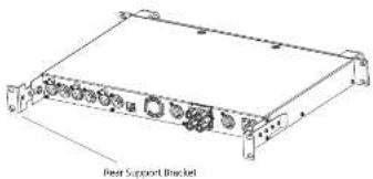
IPX 1200 - Depth is 336 mm (13.2") rack ear to back panel. Weight is approximately 5.3 kg (11.7 lbs). Rear support brackets are included and use is recommended in all applications.
IPX 2400 - Depth is 423 mm (15.7") rack ear to back panel. Weight is approximately 7 kg (15.4lbs). Rear support brackets are included and use is recommended in all applications.
IPX 4800 - Depth is 472mm (18.6") rack ear to back panel. Weight is approximately 8.4 kg (18.7 lbs). Rear support brackets are included and use is recommended in all applications.
natural_image
Technical line drawing of a rear support bracket with multiple ports and mounting feet (no text or symbols on the device itself)Cooling
Please ensure that there is sufficient space in the front and the rear of each amplifier to allow for a free flow of air. No doors or covers should be mounted either in the front or rear of the amplifiers. Amplifiers may be stacked directly on top of each other with no spacing, though some spacing may enable more convenient installation of rear cabling.
Operating voltage
All IPX Series amplifiers have a universal power supply that operates on mains from 100 – 240 V at 50 or 60 Hz. The IEC receptacle on the rear panel accepts the supplied IEC cord which terminates in a connector appropriate for the country of sale. When AC power is connected, the amplifier goes into standby (red indication on standby LED). The amplifier may be turned on by pressing the front power button or remotely using the IPX Controller software.
Grounding
Signal ground is floating via a resistor to chassis, and therefore grounding is automatic. For safety reasons, never disconnect the earth (ground) pin on the AC power cord. Use balanced input connections to avoid hum and interference
Front Panel
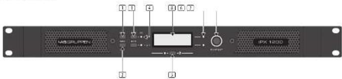
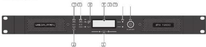
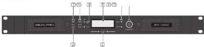
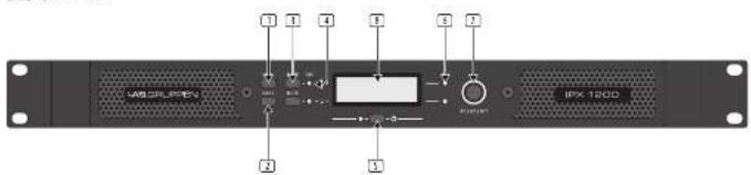
The following indicators and controls are available on the front panel:
[1] MENU – Selects MENU mode and confirms a given preset name.
[2] BACK—Moves backward through menu layers in MENU mode.
① MUTE – Mutes corresponding channel as indicated.
4 SIG - Illuminates green when signal is present. Illuminates red when signal is dipping (pre input mixer)
POWER - Indicates STANDBY (red)
LIM (limit) - illuminates when the amplifier limits the signal.
Limiting is engaged when the channel:
- Reaches the selected voltage limit
- Mains voltage cannot maintain full rail voltage
ADJUST/SET (Rotary Encoder) - Rotation moves through the menu and adjusts the currently selected parameter when in setup mode. Pressing down on the knob selects a given parameter or advances further into the menu.
In operating mode, rotation of the ADJUST/SET encoder adjusts output gain (outputs ranged).
[6] BACKLIT DISPLAY
In operating mode, the display shows the following values and status indicators:
- Level - Horizontal VU meters for each channel
• Device name and Preset name
In setup mode, the display shows currently selected menu locations and parameters.
Rear Panel
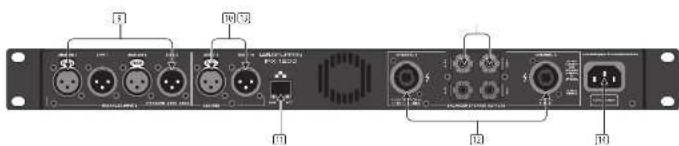
The following connectors are available on the rear panel:
(3) ANALOG INPUTS and LINK – female XLR input connectors provided for each channel, with male XLR link output connectors.
① AES3 INPUT and LINK - AES3 digital inputs are on a female XLR connector with a link output on a male XLR connector.
(3) NETWORK (Ethernet) – An R45 jack is supplied for connection to an Ethernet network for external control and monitoring, either by a direct wired connection or via an external WIFI router to an iPad or tablet. LEDs below the connector indicate valid network connection (LINK) and network activity (ACT).
12 speakON OUTPUT CONNECTORS - Both channel outputs are available on a four-pole connector at the left; either channel 1 or both channels 1 and 2 may be connected. Only channel 2 is available on the connector to the right.
BINDING POST CONNECTORS – Connectors for channel 1 and channel 2.
[16] AC LINE INPUT - A locking IEC receptacle accepts the AC line input, 50 Hz or 60 Hz, 100 V - 240 V. Use an IEC cable with the proper connector for country of use.
12 IPX Series Quick Start Guide 13
Input connections
Analog Inputs
Analog inputs are available on two standard female XLR latching connectors. The inputs are electronically balanced. The impedance is 20 kΩ, and the inputs can accept a maximum input level of +26 dBu.
Polarity is as follows:
Pin 1 = screen (shield), pin 2 = positive (+), pin 3 = negative (-).
Balanced use with XLR connectors

input
1 = around/shield
2 = hot (+ve)
3 = cold (-ve)

output
Sorubalanced use pin 1 and pin 2
have to be bridged
Analog Links
Two latching male XLH connectors are adjacent to the analog input connectors and are paralleled to the input connectors to provide an unprocessed analog loop-through to feed additional IPX Series units or other equipment.
AES3 Inputs
A latching female XLR connector accepts an AES3 digital audio signal. Input impedance is 110 Ω. (Ensure that 110 Ω digital audio cables are used; standard XLR microphone cables are rarely suitable for reliable digital audio transmission.)
AES3 is a stereo digital format, and therefore both inputs are fed via a single connector. Selection of the analog or digital inputs is made via the front panel display or IPX Controller software.
AES3 Link
A latching male XL R connector is fitted adjacent to the AES3 input connector. This is an active link which sends an unprocessed AES3 loop-thru to feed additional IPX units. The design requires no termination load when the unit is the last connected.
Output connections
Two types of power output connections are available on IPC Series amplifiers: Neutris speaRON and binding post. The two types are connected in parallel. Loudspeakers may be connected to both at the same time, but this is generally not recommended as total impedance may be too low.
Binding Posts
Power outputs for loudspeaker connection are available on two fully enclosed binding posts. Observe signal polarity as indicated.
speakON Connectors
Outputs for both channel 1 and channel 2 are available on a four-pole speakON connector to the left. The two-pole speakON to the right connect to output 2 only (see Fig. 1 below). See the amplifier's back panel for information about the available pin outs for speakON connection.

flowchart
graph TD
    A["Channel 1"] --> B["Speaker 1"]
    C["Channel 2"] --> D["Speaker 2"]
    E["Channel 1 and 2"] --> F["Speaker 1 and 2"]
Fig.1

CAUTION! When a connecting wiring to Speaker Terminals, the installation shall be made by an instructed person or ready-made leads or cords shall be used.
Bridge Mode
The IPC Series employs an inherently bridged Class D output topology.

CAUTION! Under no circumstances should the IPX Amplifier be bridged, this may cause undesired operating performance.
DSP configuration
Default configuration
IPX Series amplifiers are shipped with default DSP settings that allow immediate use in many common applications with no need for further DSP configuration.
The default mode is suited for use with the stereo program into full range
oudspeakers.
The default signal routing and parameter settings are as follows:
• Analog 1 and AES1: Routed to Ch. 1
• Apple 2 and ABC 3: Rejected to Ch. 2
• AES3 to analog failover: OFF
- Mode: Stereo
- Input levels: 0 dB
- Input EQ: Flat
- Output levels: 0 dB
- Output Mute: Muted
• Output ED: Flat
- Delay: Off
• Crossover: Off
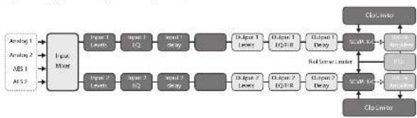
Signal flow block diagram
The block diagram below (Fig. 2) shows the signal flow from inputs to outputs
flowchart
graph LR
    A["Analog 1"] --> B["Input Mix"]
    C["Analog 2"] --> B
    D["ABS 1"] --> B
    E["ABS 2"] --> B
    B --> F["Output 1 Levels"]
    B --> G["Output 2 Levels"]
    F --> H["Input 1 EQ"]
    G --> I["Input 2 EQ"]
    H --> J["Output 1 Level"]
    I --> K["Output 2 Level"]
    J --> L["Output 1 EQ-8"]
    K --> M["Output 2 EQ-8"]
    L --> N["Output 1 Level"]
    M --> O["Output 2 Level"]
    N --> P["Output 1 EQ-8"]
    O --> Q["Output 2 EQ-8"]
    P --> R["Output 1 Level"]
    Q --> S["Output 2 Level"]
    R --> T["Output 1 Level"]
    S --> U["Output 2 Level"]
    T --> V["Output 1 Level"]
    U --> W["Output 2 Level"]
    V --> X["Output 1 Level"]
    W --> Y["Output 2 Level"]
    X --> Z["Output 1 Level"]
    Y --> AA["Output 2 Level"]
    Z --> AB["Output 1 Level"]
    AA --> AC["Output 2 Level"]
    AB --> AD["Output 1 Level"]
    AC --> AE["Output 2 Level"]
    AD --> AF["Output 1 Level"]
    AE --> AG["Output 2 Level"]
    AF --> AH["Output 1 Level"]
    AG --> AI["Output 2 Level"]
    AH --> AJ["Output 1 Level"]
    AI --> AK["Output 2 Level"]
    AJ --> AL["Output 1 Level"]
    AK --> AM["Output 2 Level"]
    AL --> AN["Output 1 Level"]
    AM --> AO["Output 2 Level"]
    AN --> AP["Output 1 Level"]
    AO --> AQ["Output 2 Level"]
    AP --> AR["Output 1 Level"]
    AQ --> AS["Output 2 Level"]
    AR --> AT["Output 1 Level"]
    AS --> AU["Output 2 Level"]
Fig.2
Front panel configuration
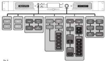
Input mixing and routing, as well as all DSP parameters, may be configured using the Menu and Back buttons and the Adjust/Set rotary encoder (see Fig. 3 below):
flowchart
graph TD
    A["Input Data"] --> B["Data Processing Unit"]
    B --> C{Decision}
    C -->|Yes| D["Output Data"]
    C -->|No| E["Feedback Loop"]
    E --> B
    D --> F["Output Data"]
    F --> G["Data Processing Unit"]
    G --> H{Decision}
    H -->|Yes| I["Output Data"]
    H -->|No| J["Feedback Loop"]
    J --> E
    style A fill:#f9f,stroke:#333
    style B fill:#ccf,stroke:#333
    style C fill:#cfc,stroke:#333
    style D fill:#fcc,stroke:#333
    style E fill:#cff,stroke:#333
    style F fill:#ffc,stroke:#333
    style G fill:#cfc,stroke:#333
    style H fill:#fcc,stroke:#333
    style I fill:#ffc,stroke:#333
    style J fill:#cfc,stroke:#333
IPX Controller software and network configuration
Software and App Downloads and Installation
For download of the IPX Controller software for Mac and PC, please visit www.labgruppen.com. Instructions for installation are available via this link.
Network configuration
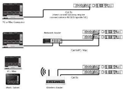
A network of IPX amplifiers may be configured using standard, off-the-shelf Ethernet router and shielded Cat-S cabling. If the router is WiFi enabled, the IPX amplifier network will be accessible using a laptop computer running IPX Controller software.
The IPX network employs a star topology only. Each amplifier must be connected individually to the router.
Network configuration is automatic. Each amplifier is identified by a unique IP address, which is shown in the Global view and the device header panel of IPX Controller.
Input mixing/routing and DSP configuration using IPX Controller
All input mining /routing functions and DSP configuration parameters are accessible and adjustable using IPX Controller software. The device header panel appears at the top of each configuration window for a selected device.
flowchart
graph TD
    A["PC or Max Computer"] --> B["Cat To"]
    B --> C["Direct connection may require converted hardware (NLS) optional NC"]
    D["Network Router"] --> E["CatSePC / Mac"]
    F["PCI / Tablet"] --> G["Cat Se"]
    G --> H["Wireless Router"]
    I["iPad / Tablet"] --> J["Cat Se"]
Global
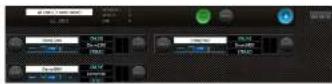
The Global view shows all devices on the network and accesses the following functions:
- Naming devices (amplifiers) and groups
- furring groups of devices
- Creating and deleting groups
- Muting amplifiers individually or in groups
• Power On/Off individually or in groups - Monitoring of output levels
• Devices selected for a group are controlled simultaneously from any of the device kits in that group.
Device Header

The device header panel appears at the top of each configuration window for a selected device. The header panel accesses the following functions and information:
- Return to Global
• Power on/off - Output mute (per channel)
• Device name - Online/Offline indication
- IP address
• Temperature reading - Current preset
- Preset store and recall (device or computer)
Input Mixer
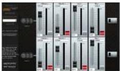
The Input Microview accesses the following functions:
• Device set up (stereo or 2-way mode)
- Input mixing
- AES3 to analog failover on/off
Levels
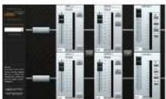
The Levels view accesses the following functions:
- Input Mix Bus Levels
- Output levels
- Output limiters
- Linking of inputs and outputs.
Input EQ
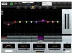
Input EQ view is selectable per channel. Input EQ accesses the following functions:
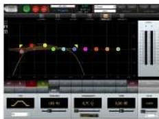
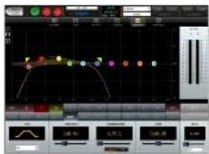
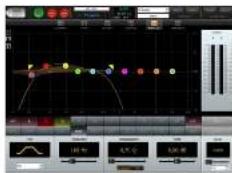
- Parametric equalizer (up to 10 bands)
• Output level status - Input delay (up to 2 sec)
Crossover and Output EQ
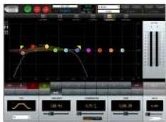
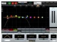
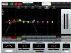
Output EQ view is selectable per channel. The Output EQ view accesses the following functions:
- Parametric equalizer (up to 10 bands)
- Output level status
- Output delay (up to 2 sec)
• High pass filter
• High pass filter type
• High pass filter cutoff frequency
- Low pass filter
- Low pass filter type
- Low pass filter cutoff frequency
FIR-X Mode:
To enabled FIR-X Mode device must be in Developer Mode. When FIR-X mode enabled, the normal Output EQ interface is disabled. See "IPX Preset Locking Guide" for further information.
Factory reset
A factory reset can be carried out from the front panel of the device. Disconnect completely from mains power. Press and hold both mute buttons on the front panel while powering the device up. A factory reset menu is now displayed.
Introducción
natural_image
Technical line drawing of a rectangular electronic device with multiple ports and mounting brackets (no text or symbols)Peer Support Bracket
Peer Support Bracket
18 EX Series
Quick Star Guide
19
Panel frontal
Balanced use with XLR connectors

input
1 = ground/shield
2 = hot (+ve)
3 = CDKs (-ve)

output
For unbalanced use, pin 1 and pin 3 have to be bridged.
flowchart
graph TD
    A["Channel 1"] --> B["Speaker 1"]
    C["Channel 2"] --> D["Speaker 2"]
    E["Channel 1 and 2"] --> F["Speaker 1"]
    G["Channel 1 and 2"] --> H["Speaker 2"]
Fig.1

Crossover and Output EQ
natural_image
Technical line drawing of a rear support bracket with multiple ports and mounting feet (no text or symbols)Refroidissement
All IPX Series amplifiers have a universal power supply that operates on mains from 100 - 240 V at 50 or 60 Hz. The IEC receptacle on the rear panel accepts the supplied IEC cord which terminates in a connector appropriate for the country of sale. When AC power is connected, the amplifier goes into standby (red indication on standby LED). The amplifier may be turned on by pressing the front power button or remotely using the IPX Controller software.
Masse
Balanced use with XLR connectors

input
1 = ground/shield
2 = hot +vel
3-cold (ve)

output
For unbalanced use, pin 1 and pin 3
have to be bridged
Sorties LINK analogiques
flowchart
graph TD
    A["Channel 1"] --> B["Channel 1 and 2"]
    C["Channel 2"] --> D["Channel 2"]
    E["Channel 3"] --> F["Channel 3"]
Fig.1

Crossover and Output EQ
Vorderseite
Balanced use with XLR connectors

input
1 = ground/shield
2 = hot(+ve)
3 = cpkt(-ve)

output
For unbalanced use, pin 1 and pin 3
have to be bridged
Analoge Links
Fig.1

Crossover and Output EQ
natural_image
Technical line drawing of a rack support bracket (no text or symbols on the device itself)Resfriamento
Balanced use with XLR connectors

input
1 = ground/shield
2 = hot +vel
3-cold (ve)

output
For unbalanced use, pin 1 and pin 3 have to be bridged
Links analógicos
flowchart
graph TD
    A["Channel 1: left through top line"] --> B["Speaker 1"]
    C["Channel 1 and 2"] --> D["Speaker 2"]
    E["Channel 2"] --> F["Speaker 3"]
Fig.1

Crossover and Output EQ
natural_image
Technical line drawing of a rear support bracket with multiple ports and mounting brackets (no text or symbols)Raffreddamento
Balanced use with XLR connectors

input
1 = ground/shield
2 = not (+ve)

output
For unbalanced use, pin 1 and pin 3
have to be bridged
LINK analogici
flowchart
graph TD
    A["Channel 1: port through to top box"] --> B["Speaker 1"]
    C["Channel 2: channel 1"] --> D["Speaker 2"]
    E["Channel 3 and 2"] --> F["Speaker 3"]
Fig.1

Crossover and Output EQ
natural_image
Technical line drawing of a rack support bracket (no text or symbols on the device itself)Koeling
Balanced use with XLR connectors

input
1-ground/shield
2-hat (+ve)
3-cold (-ve)

output
For unbalanced use, pin 1 and pin 3 have to be bridged
Analoge koppelingen
Crossover and Output EQ
Kylning
Balanced use with XLR connectors

input
1 = ground/shield
2 = hot (+ve) 3 = cpk(-ve)

output
For unbalanced use, pin 1 and pin 3
have to be bridged
Analoga länkar
Crossover and Output EQ
according to the journal information
Factory reset
natural_image
Technical line drawing of a four-support bracket with multiple ports and mounting feet (no text or symbols)Chłodzenie
Balanced use with XLR connectors

input
1 = ground/shield
2 = hot +vel
3-cold (ve)

output
For unbalanced use, pin 1 and pin 3 have to be bridged
flowchart
graph TD
    A["Channel 1: 6x6x6x7"] --> B["Channel 1: 6x6x6x7"]
    C["Channel 2: 6x6x6x7"] --> D["Channel 2: 6x6x6x7"]
    E["Channel 1: 6x6x6x7"] --> F["Channel 1: 6x6x6x7"]
    G["Channel 2: 6x6x6x7"] --> H["Channel 2: 6x6x6x7"]
Rg.1

Crossover and Output EQ
natural_image
Technical line drawing of a rectangular electronic device with multiple ports and mounting brackets (no text or symbols)Rear Support Bracket
前面パネル
Balanced use with XLR connectors


output
For unbalanced use, pin 1 and pin 3 have to be bridged
アナログリンク
flowchart
graph TD
    A["Speaker 1"] --> B["Channel 1 and 2"]
    C["Speaker 2"] --> D["Channel 1"]
    E["Speaker 3"] --> F["Channel 1 and 2"]
    G["Speaker 4"] --> H["Channel 1 and 2"]
Fig.1

| IPX2200 IPX2400 IPX4800 | |||
| Maximum Output Power* | |||
| 2.0 per channel, stereo 500 V/100 V/2400 V | |||
| 4.0 per channel, stereo 600 V/1200 V/2400 V | |||
| 8.0 per channel, stereo 300 V/600 V/1200 V | |||
| Controls | |||
| Front Power switch | DSP section rotary push-encoderButtons for Micro, Back, Mute (per channel) | ||
| System | |||
| Number of channels 2 | |||
| Output voltage | 70 V peak / 50 Vrms / 36.2 dBu | 100 V peak / 70 Vrms / 39.2 dBu | 140 V peak / 100 Vrms / 42.2 dBu |
| Input sensitivity for maximum output voltage | 6 dBu | ||
| Output current | 16 A rms | 20 A rms | 35 A rms |
| Output circuit type | Class-D | ||
| T/D > N | < 0.1% , 20 Hz - 20/Hz ≤ 1.19< 0.05% ≥ 1.1Hz, 1 dB below clip | ||
| Output noise | -66 dBu, A-weighted | -65 dBu, A-weighted | -64 dBu, A-weighted |
| Signal to noise | > 100 dB | > 104 dB | > 106 dB |
| Channel controls | > 0.05% @ 1 dB | ||
| Frequency response | 10 Hz to 20 kHz, +0.5/-1 dB5 Hz to 90 kHz, -3 dB | ||
| Common mode injection (CIRF) | > 50 dB | ||
| Gain tail DSP controls set to 0 dB | 30 dB | 33 dB | 36.2 dB |
| Indicators | |||
| Power | Rod LED | ||
| Limit, per channel | Rod LED | ||
| Signal / mute, per channel | Green/Rod LED | ||
| Digital Signal Processing (DSP) | |||
| Display | LED: 128 x 32, while buffer | ||
| Functions | 40 multi-slope parametric equations, FIR.Adjunctable high- and low-pass filtersInput and output delays (up to 2 seconds each)Crossave with multiple filters (types) | ||
| Presets | Support up to 50 presets | ||
| Connectors | |||
| Analog inputs | 2 x XLR | ||
| Analog input impedance | 18 kΩ unbalanced, 16 kΩ balanced | ||
| Maximum analog input level | 20 dBu | ||
| Digital Inputs | 1 x XLR (AESS digital format) | ||
| Unit outputs (analog) | 2 x XLR | ||
| Unit output (digital) | 1 x XLR (AESS digital format) | ||
| Speaker outputs | 7 x keyboard speaker (WIT4)2 x branding posts | ||
| Network control | 1 x 645 | ||
EN
| IPX200 | IPX2400 | IPX6800 | |
| Circuit protection | |||
| Coating | Continuously variable speed lonFront to back air flow | ||
| Amplifier protection | Thermal and DC protectionSubtle into discrete or instantaneous loads | ||
| Circuit protection | Controlled start and shutdown behavior, DC lock protection | ||
| Power Supply, Voltage, (Breaker) | |||
| Switch-mode autotrage power supply | 100-240 V~30/50 Hz | ||
| Power consumption x 1/2 mixed power | 250 N | 500 N | 1000 W |
| Standby consumption | <7 W | ||
| Main connection | Standard locking ICL receptible | ||
| Dimension/Weight | |||
| Dimension (x 10 x 30) | 44 x 483 x 336 mm(1.7 x 19.0 x 13.2") | 44 x 483 x 423 mm(1.7 x 19.0 x 13.2") | 44 x 483 x 472 mm(1.7 x 19.0 x 10.6") |
| Weight | 5.1 kg (11.2 lbs) | 2.0 kg (15.4 lbs) | 3.4 kg (15.7 lbs) |
*Independent of limiters and driver protection circuits
Other important information

Important information
- Register online. Please register your new Music Tribe equipment right after you purchase it by visiting muscrite.com. Registering your purchase using our simple online form helps us to process your repair claims more quickly and efficiently. Also, read the terms and conditions of our warranty, if applicable.
- Malfunction. Should your Music Tribe Author and Reseller not be located in your vicinity, you may contact the Music Tribe Authorized Further for your country listed under "Support" at musictribe.com. Should your country not be listed, please check if your problem can be dealt with by our "Online Support" which may also be found under "Support" at musictribe.com. Alternatively, please submit an online warranty claim at musictribe.com BEFORE returning the product.
- Power Connections. Before plugging the unit into a power socket, please make sure you are using the correct mains voltage for your particular model. Equity fuses must be replaced with fuses of the same type and rating without exception.

Responsible Party Name: Music Tribe Commercial NV Inc.
Address: 122 E. 42nd St.1,
8th Floor NY, NY 10168, United States
Email Address: legal@musictribe.com
IPX Series
This equipment has been tested and found to comply with the limits for a Class A digital device, pursuant to part 15 of the FCC Rules. These limits are designed to provide reasonable protection against harmful interference when the equipment is operated in a commercial environment. This equipment generates, uses, and can radiate radio frequency energy and, if not installed and used in accordance with the instruction manual, may cause harmful interference to radio communications. Operation of this equipment in a residential area is likely to cause harmful interference in which case the user will be required to correct the interference at his own expense.
This equipment complies with Part 15 of the FCC rules. Operation is subject to the following two conditions:
(1) this device may not cause harmful interference, and (2) this device must accept any interference received, including interference that may cause undesired operation.
Warning: Operation of this equipment in a residential environment could cause radio interference.
Important Information: Changes or modifications to the equipment not expressly approved by Music Tribe can void the user's authority to use the equipment.
CE
Hereby, Music Tribe declares that this product is in compliance with Directive 2014/35/EU, Directive 2014/30/EU, Directive 2011/65/EU and Amendment 2015/863/EU, Directive 2012/19/EU, Regulation 519/2012 REACH SVHC and Directive 1907/2006EC.
Full text of EU DoC is available at https://community.musictribe.com/
EU Representative: Music Tribe Brands DK A/S Address: Gammel Strand 44, DK-1202 Kopenhagen K, Denmark
UK Representative: Music Tribe Brands UK Ltd. Address: 8 th Floor, 20 Farrington Street London EC4A 4AB, United Kingdom

Correct disposal of this product: This symbol indicates that this product must not be disposed of with household waste, according to the WEEE Directive (2012/19/EU) and your national law. This product should be taken to a collection center licensed for the recycling of waste electrical and electronic equipment (EEE). The mishandling of this type of waste could have a possible negative impact on the environment and human health due to potentially hazardous substances that are generally associated with EEE. At the same
time, your cooperation in the correct disposal of this product will contribute to the efficient use of natural resources. For more information about where you can take your waste equipment for recycling, please contact your local city office, or your household waste collection service.
- LEGAL DISCLAIMER
- LIMITED WARRANTY
- BESCHRÄNKTE GARANTIE
- m = 311
- KENNING
- Unpacking and visual checks
- Installation
- Cooling
- Operating voltage
- Grounding
- Input connections
- Analog Inputs
- Analog Links
- AES3 Inputs
- AES3 Link
- Output connections
- Binding Posts
- speakON Connectors
- DSP configuration
- Default configuration
- Signal flow block diagram
- Front panel configuration
- IPX Controller software and network configuration
- Network configuration
- Input mixing/routing and DSP configuration using IPX Controller
- Global
- Device Header
- Input Mixer
- Levels
- Input EQ
- Factory reset
- Introducción
- Refroidissement
- Masse
- Sorties LINK analogiques
- Analoge Links
- Resfriamento
- Links analógicos
- Raffreddamento
- LINK analogici
- Koeling
- Analoge koppelingen
- Kylning
- Analoga länkar
- Chłodzenie
- アナログリンク
- EN
- Other important information
- Important information
- IPX Series
- CE
Brand : Lab Gruppen
Model : IPX 4800
Category : Receiver