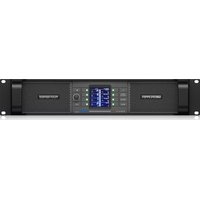
PLM 5K44 - Receiver Lab Gruppen - Free user manual and instructions
Find the device manual for free PLM 5K44 Lab Gruppen in PDF.


| Product Type | Powered Loudspeaker Management System / Amplifier |
| Model | PLM 5K44 |
| Brand | Lab Gruppen |
| Amplifier Output Power | 5000 W (total, 4 channels) |
| Number of Amplifier Channels | 4 |
| DSP Features | EQ, crossover, delay, limiter, FIR filters, dynamics processing |
| Network Connectivity | Ethernet for control and monitoring via Lake Controller |
| Analog Inputs | 4 balanced XLR/TRS combo jacks |
| Analog Outputs | 4 balanced XLR (line level) |
| Loudspeaker Outputs | 4 Speakon NL4 connectors |
| Power Supply | 100-240 V AC, 50/60 Hz, auto-ranging |
| Cooling | Variable-speed fans, front-to-rear airflow |
| Dimensions (W x H x D) | 483 x 88 x 400 mm (19"/2U) |
| Weight | Approximately 14 kg (30.9 lbs) |
| Protection Features | Short circuit, thermal, overcurrent, DC offset, mains protection |
| Maintenance | Keep vents clean; periodic inspection of connections and cooling fans |
| Safety | Class 1 equipment; connect to grounded outlet; do not block ventilation |
| Repairability / Spare Parts | Serviceable by authorized technicians; filter air intake regularly |
Frequently Asked Questions - PLM 5K44 Lab Gruppen
User questions about PLM 5K44 Lab Gruppen
0 question about this device. Answer the ones you know or ask your own.
Ask a new question about this device
Download the instructions for your Receiver in PDF format for free! Find your manual PLM 5K44 - Lab Gruppen and take your electronic device back in hand. On this page are published all the documents necessary for the use of your device. PLM 5K44 by Lab Gruppen.
USER MANUAL PLM 5K44 Lab Gruppen
2.1 Computer Requirements....5 2.2 Lake Controller Installation....10 2.3 Moving User Files between Installations 11
3. Network & Firewall Overview....12
3.1 Ethernet Overview 12 3.2 Firewall Configuration....13 3.3 IP Address Configuration 14 3.4 Wired Network Setup 17 3.5 Wireless Network Setup 19 3.6 Dante and AES67 Digital Audio Networking....22
4. Lake Controller Tutorial ......27
4.1 Starting the Lake Controller 27 4.2 Overview of Main Page Components....28 4.3 Modules and Frames 31 4.4 Equalization 47 4.5 Crossovers 55 4.6 Groups....57 4.7 Lake Controller File Types 59
5. Home Menu Reference....62
5.1 Main Screen Home Menu....62 5.2 Accessing EQ/Levels from HOME....64
6. EQ/Levels Menu Reference 65
6.1 EQ/Levels Overview 65 6.2 Levels 68 6.3 Input EQ 79 6.4 Crossovers and HPF/LPF 94 6.5 Auxiliary Output Channels....106
7. System Store Recall Menu Reference.... 114
7.1 System Store Recall Navigation 114 7.2 Shortcut to Data/User Folder 114 7.3 Recall as New System—Open 115 7.4 Recall as Subsystem 115 7.5 Recall Compare 115 7.6 Recall as Virtual Sub System (SS) 116 7.7 Store System....117 7.8 Store Subsystem.... 117 7.9 File Utilities 117 7.10 System Presets 119
8. Modules Menu Reference....123
8.1 EQ/Levels....123 8.2 I/O Config....123 8.3 Label & Lock 156 8.4 Copy/Paste/Replace 158 8.5 Remove....162 8.6 Module Store/Recall 162 8.7 Add Page....167 8.8 Super Modules (LM & PLM Series only) 167
9. Module File Types & Lake LoadLibrary™ 171
9.1 Module Types Overview....171 9.2 Supplementary Module Data 171 9.3 Module Type Abbreviations....172 9.4 Classic Crossovers/Auxiliary Outputs....173 9.5 Linear Phase Crossovers....178 9.6 FIR Module....180 9.7 XP Module [PLM+ and D Series only] 182 9.8 Mesa EQ Module....184 9.9 Lake LoadLibrary 185 9.10 Additional Information 185
10. Groups Menu Reference....186
10.1 Adding a Group 186 10.2 EQ/Levels....187 10.3 Assign 187 10.4 Label 189 10.5 Copy/Paste 189 10.6 Remove....190 10.7 Gang....190 10.8 Add Page 191 10.9 Discovering Module Group Assignments.... 191
11. Solo/Mute Menu Reference 192
11.1 EQ/Levels....192 11.2 Solo/Mute Enable 192 11.3 Pile 193 11.4 All Mute....193
12. Icon Control Menu Reference....194
12.1 Meters On/Off 194 12.2 Fast Meters 194 12.3 Icon Small/Normal/Medium/Large....194
13. User Preferences Menu Reference 195
13.1 Contexts 195 13.2 Delay Units 195 13.3 Designer Functions 196 13.4 Keyboard Shortcuts....197 13.5 About 197 13.6 Graphics 197 13.7 Show Mode....199
14. Pages Menu Reference....200
14.1 Cut Icon 200 14.2 Copy Icon 201 14.3 Paste Icon 201 14.4 Page Label 201 14.5 Page Delete 202 14.6 Page Add....202 14.7 Page Hide....202 14.8 Scrolling Pages....202
15. Network Menu Reference....203
15.1 Network 203 15.2 Multiple Controllers....204 15.3 Working Offline 206
16. Communication and Synchronization ....208
16.1 Offline Modules 208 16.2 Communication/Network Errors 208 16.3 Synchronization....209
17. Faults and Warnings....214
17.1 Faults and Warnings Indication 214
18. Analyzer Plug-in....216
18.1 Overview....216 18.2 System Requirements.... 217 18.3 Analyzer Plug-in Quick Start Guide 218 18.4 Function Reference 219
19. Designer Mode Menu Reference....229
19.1 Designer Mode Basics 229 19.2 Designer Mode Security 232 19.3 Functional Reference Guide....243 19.4 Designer Worksheets....250
20. Lake-enabled Amplifier Reference 257
20.1 Signal Flow 258 20.2 Monitoring & Control....258 20.3 Lake LoadLibrary™ 258 20.4 LoadSmart™ 258 20.5 Navigation 259 20.6 Status Tab 259 20.7 History Tab 263 20.8 Events Tab 265 20.9 LoadSmart Tab 266 20.10 Output Tab 270 20.11 Power 274
21. LM Series Reference and Operation....275
21.1 Pass-Thru Input Router Functionality 275 21.2 GPIO Configuration 278 21.3 Remote Power Control & Event Logs 278
22. MY8-LAKE Reference and Operation 281
22.1 Signal Flow....281 22.2 Operation Mode 284 22.3 Host Analog Output Reference Configuration 284 22.4 I/O Configuration View Mode Options....285
23. Global Events and Control....287
23.1 Global Events Tab....287 23.2 Global Control Tab 290 23.3 Array Opt (XP Modules only)....294 23.4 Log Files....296
24. Keyboard Shortcuts....297
24.1 Enabling/Disabling Keyboard Shortcuts 297 24.2 General Keyboard Shortcuts 297 24.3 Button Bar Shortcuts....297 24.4 EQ, LEVELS, XOVER, and AUX Screen Shortcuts 298
25. External Control Interfaces ....303
25.1 GPIO (LM Series Only)....303 25.2 AMX® and Crestron® Control....303 25.3 Q-SYS Plugin....304
26. Command Line Options 305
26.1 Overview....305 26.2 Reference....305
27. Firmware Update....308
27.1 Backup System Configuration and Presets 308 27.2 Updating Firmware....308 27.3 Incompatible Firmware Notification in Lake Controller 311 27.4 Remote Power Cycle 312
28. Preset Manager....313
28.1 Starting the Lake Preset Manager 313 28.2 Screen Layout 314 28.3 Working with Frames 315 28.4 Working with Bank Files 318 28.5 Common Functionality 323
29. IP Address Reference 324
29.1 Network Essentials 324 29.2 Factory Reset Configuration....324
30. Corporate Information 326
30.1 Contact Details....326 30.2 Trademarks....326
1. Welcome
1.1 Important Information
In January 2009, Lab.gruppen acquired from Dolby Laboratories, Inc. both the Lake trademarks and the exclusive rights for use of Dolby® Lake® Processor technology for both touring and permanent sound reinforcement markets. Lab.gruppen is now developing the Lake Processing technology and the Controller software independently for these markets. The Lab.gruppen-developed Controller software version will be forthwith named Lake Controller software.
1.2 Introduction
The Lake Controller software provides a unified interface for the Lab.gruppen PLM™ Series, PLM+ Series, D Series, Lake LM Series and the MY8-LAKE (Yamaha Mini-YGDAI). Optimized for a wireless touch-screen or Tablet PC, the Controller uses a unique Graphic interface that brings back the feel of analog faders and controls. The software operates on any Microsoft® Windows® PC with a standard Ethernet network interface.
The Lake Controller may also be accessed via media tablet devices such as the Apple® iPad™ by using remote desktop connectivity software that requires additional configuration. For further details on configuring the Lake Controller for use via a media tablet, please refer to the Product Documentation category of the support section at http://lakeprocessing.com.
This manual describes the functionality of the Lake Controller software suite, including the main Lake Controller component, along with associated Firmware Update Utilities and Preset Manager Utilities.
For a full understanding of the Lake Controller System, use this manual together with associated hardware operation manuals, audio networking information and quick reference guides that are provided in the documentation folder of your software installation.
Note that the Lake Controller software has all necessary functionality to control the Lake LM Series devices, Lab.gruppen PLM, PLM+ and D Series devices and the MY8-LAKE (Yamaha Mini-YGDAI). Support for legacy devices including the Dolby Lake Processor™, Contour Pro 26™ and Mesa Quad EQ™ discontinued in Lake Controller v6.x; for control of these devices please use Lake Controller v5.x.
Throughout this manual, the generic term ‘device’ will be used to describe any hardware product containing Lake Processing technology.
1.3 Controller Overview
Using the Controller software, a sound engineer can control a distributed network of Lake devices from a single location. Instant adjustments can be made to any parameter of any device on the network, or to selected device Groups. By creating Groups, the Controller can deliver the appropriate EQ and level settings to a large, segmented sound system.
A single device can belong to multiple Groups (up to 28); for example, a traditional arena-sized system comprises several left and right main stacks, side-, front-, and down-fills, and multiple levels of delays to different subsystems. Typical technology requires a chain of processing units to enable an overall stereo master and various sub-masters to individually control equalization, dynamics, and gain.
In contrast, the Controller can use multiple Groups to send global adjustments to all PA areas while still providing independent control of individual system components.
1.4 Manual Overview
This operation manual provides software installation instructions, a tutorial for new users, and full-detail reference information for all software functions and features of the Lake Controller user interface.
The manual is organized as follows:
Chapter 1, Welcome, this chapter.
Chapter 2, Software Installation, provides details for installing the Lake Controller software, along with information for configuring various Tablet PC related options. Chapter 3, Network & Firewall Overview, provides information for PC networking and firewall configuration, and verifying of both wired and wireless Lake Controller and device connectivity. Chapter 4, Lake Controller Tutorial, provides a tutorial that introduces the features of the software, and the terminology utilized in the user interface. Chapter 5, Home Menu Reference, describes the top-level functions of the button bar located at the bottom of the Lake Controller user interface. Chapter 6, EQ/Levels Menu Reference, details the functions found within the EQ/Levels menu. This menu provides the most commonly used functions within the Lake Controller. Chapter 7, System Store Recall Menu Reference, describes menu functions related to saving and recalling system configuration files. Chapter 8, Modules Menu Reference, details the functions found on the Modules Menu, including how to store and recall Module files, Super Module functionality, adjusting the I/O configuration of Modules and Super Modules, and accessing other Module-specific functions.
Chapter 9, Module File Types & Lake LoadLibrary™, provides a reference for the available Module file types, including traditional crossovers, linear phase crossovers, and Mesa EQ Modules. Chapter 10, Groups Menu Reference, describes Groups, which provide a sophisticated way to partition complex systems, enabling system-wide control of EQ and Levels in real time. This chapter details all functions related to creating and assigning Modules to Groups. Chapter 11, Solo/Mute Menu Reference, describes functionality relating to Solo/Mute. Chapter 12, Icon Control Menu Reference, describes how to change the size of Module icons within the interface, as well as how to change meter icon views. Chapter 13, User Preferences Menu Reference, provides explanation of the functions contained in the User Preferences menu, including access to Designer Mode, daylight operation, Show mode, and more. Chapter 14, Pages Menu Reference, details the functions associated with adding and naming new page displays within the user interface. Chapter 15, Network Menu Reference, describes how to change between available networks, along with details on Multiple Controller functionality. Chapter 16, Communication and Synchronization, describes how the Lake Controller synchronizes to Lake devices, and provides explanations and suggestions on how to resolve issues that may arise due to network problems, such as moving out of range of a wireless access point. Chapter 18, Analyzer Plug-in, details the functionality of the analyzer plug-in that enables the Lake Controller to display and control third-party analyzers. Chapter 19, Designer Mode Menu Reference, details the security features provided by the Designer Mode of operation. Chapter 20, Lake-enabled Amplifier Reference, provides Lake Controller specific information relevant to all Lake-enabled amplifiers (PLM, PLM+ and D Series). Chapter 21, LM Series Reference and Operation, provides Lake Controller specific information relevant to the LM Series devices. Chapter 22, MY8-LAKE Reference and Operation, provides Lake Controller specific information relevant to MY8-LAKE devices. Chapter 23, Global Events and Control, details the Lake Controller global functions for system control and logging. Chapter 24, Keyboard Shortcuts, details the available Lake Controller keyboard shortcuts. Chapter 25, External Control Interfaces, describes the available external-control interfaces supported by the Lake Controller, including GPIO, AMX®, Crestron®.
Chapter 26, Command Line Options, provides the list of available switches that can be used when starting the Lake Controller to provide alternate functionality. Chapter 27, Firmware Update, presents the methods in which you can update the firmware of your Lake device using the associated Firmware Update Utilities. Chapter 28, Preset Manager, provides information on using the separate Preset Manager utilities that are provided in the Lake Controller software suite. Chapter 29, IP Address Reference, provides reference information for configuring IP addresses for the Lake Controller and Lake device network.
If you are using the Controller for the first time, please read the tutorial in chapter 4 to become familiar with the features and terminology. For information on Lake device hardware and front panel functionality, please refer to the associated operation manuals.
The information in this manual is based on the use of a touchscreen Tablet PC, which utilizes a pen interface instead of a mouse. Therefore the word TAP is used instead of CLICK when referring to tapping the pen on the screen, which is equivalent to clicking the left mouse button. If you are using a mouse instead of a pen, substitute a click of your left mouse button when instructed to tap.
2. Software Installation
These software installation instructions assume some basic knowledge of Microsoft Windows concepts, such as selecting menu items, locating folders and files, and starting programs. For more information on Windows, please consult your Windows documentation.
Before installing the Lake Controller software, please read the license agreement presented at the beginning of the Lake Controller software installer.

It is highly recommended that the video card driver is updated to the latest version prior to installing the Lake Controller software.
2.1 Computer Requirements
This section describes the recommended computer specifications and settings for optimal use of the Lake Controller software.
2.1.1 General PC Requirements
Microsoft DirectX 8.1 or later
100/1000 Base-T wired Ethernet adapter and/or 802.11 wireless Ethernet adapter. Latest video card drivers downloaded and installed from the manufacturer's website.
2.1.2 Recommended PC Specifications
The recommended computer specifications for using the Lake Controller software are:
1.5 GHz Dual Core Processor or faster; 1 GB RAM or greater
▶ 256 MB video RAM or greater (ensure latest video drivers are installed)
▶ Windows 7 or later ▶ A touch-screen Tablet style interface
2.1.3 Minimum PC Specifications
The minimum computer specifications for using the Lake Controller software are:
1 GHz Processor (for Intel Atom processors the 'emulation' command line option is required - please refer to "26. Command Line Options" on page 305)
▶ 512 MB RAM
128 MB video RAM WinXP, 'emulation' for Win 7 (ensure latest video drivers are installed)
▶ Windows XP Service Pack 3 or later
▶ A screen resolution of at least 1024 x 768 (800 x 600 works as well, but with reduced user experience, with some features not directly accessible)
2.1.4 Video Card Settings
It is important that the video card is configured correctly to ensure smooth operation of the Lake Controller software. Incorrect video card settings may result in corruption of Graphics, unusual behavior, or unexpected exit of the Lake Controller software.
In addition to the settings presented below, please visit your video card manufacturer's website and download the latest drivers for your specific video card. The video drivers that come pre-installed with Windows are often out of date and do not include enhancements provided by the video card manufacturer's drivers. Almost all video card issues can be resolved by updating your video card driver to the latest release version.

It is highly recommended that the video card driver is updated to the latest version if you encounter any Graphical problems when using the Lake Controller software.
For optimal results, please ensure the follow settings are made on your Lake Controller PC:
A display resolution of 1024 x 768 pixels or greater is recommended. Resolutions of 800 x 600 and 1024 x 600 pixels are supported, but provide a lower-quality interface with some features less accessible or unavailable. - Color should be set to 32-bit (does work with 16 bit, but screen minimize / maximize is faster with a 32-bit color mode setting). ▶ 3D Acceleration set for best performance with anti-aliasing turned off.
For high resolution tablets running Windows 8.1 or later, the Lake Controller enables Windows DPI scaling. If native resolution is preferred, right-click the Lake Controller executable, select the Compatibility tab, and select Disable scaling for High-DPI. This option may improve performance on low specification processors.
2.15 Tablet PC and Laptop Power Settings
When using a wireless laptop or Tablet PC with the Lake Controller, you may need to switch off power-saving features, which can reduce the performance of your PC.
If you experience slower performance while using the Controller on battery power, turn off any battery power-saving settings that affect general performance of your PC. Some battery optimizations also affect wireless connection speed; if you experience a slow wireless connection while in Battery mode, these settings should be disabled.
To turn off power-saving features, navigate using the Windows Control Panel:
- Go to Windows Start Menu > Settings > Control Panel > Power Options
- As settings vary depending on each Tablet or laptop, please consult the appropriate hardware manual for further information.

Figure 2-1: Power Option Properties
2.1.6 Tablet PC Input Panel Settings
Windows XP Tablet Edition provides the pen action Start Input Panel gesture, which starts the Tablet Input Panel (keyboard or writing pad). This gesture is a quick movement of the pen from side to side. If the Input Panel appears while using the Lake Controller, it will cause flickering because both the Controller and the Input Panel attempt to be in the foreground.
To disable the Input Panel gesture:
- Access TABLET AND PEN SETTINGS through the Windows Control Panel.
Start Menu > Settings > Control Panel > Tablet and Pen Settings, Pen Options
- Select PEN OPTIONS.

Figure 2-2: Tablet and Pen Settings
- Select START INPUT PANEL GESTURE, and tap SETTINGS.

Figure 2-3: Disabling Start Input Panel Gesture
- Uncheck ENABLE START INPUT PANEL GESTURE.
- Tap OK.
- Tap OK again to store your changes.
2.2 Lake Controller Installation
2.2.1 First Time Lake Controller Installation
To install the Lake Controller software suite, insert the installer CD-ROM or USB key into your computer or double-tap the executable installer that was downloaded via the Internet; choose INSTALL LAKE CONTROLLER then follow the on-screen setup instructions.
- Read installation information, and tap NEXT to proceed through the installation dialog boxes.
- Tap INSTALL when requested.
- Tap FINISH when installation is complete.
Following successful installation, the Lake Controller icon appears on the desktop.

Before using the Lake Controller with a network of Lake devices, please follow the configuration procedures described in chapter 3.
2.2.2 Overwriting Existing Lake Controller Installation
Overwriting an existing installation requires that both the Installation and Shortcut folders be identical to those of the existing installation.
If you decide to overwrite your existing installation, ensure that you specify the same location during the software installation process.
2.2.3 Multiple Lake Controller Installations
If you wish to retain previous versions of the Lake Controller, please ensure that the installation location specified during software installation is unique.

Only one instance of the software may be used at any one time. Be aware that different versions of the software are only compatible with certain firmware versions.
2.3 Moving User Files between Installations
To copy preset files from an existing (old) installation to a new Lake Controller installation.
- Tap Windows Start > All Programs > Lake Controller vX.X > User Data Files Where X.X is previous version of the Lake Controller installation.
- Tap Windows Start > All Programs > Lake Controller vY.Y > User Data Files Where Y.Y is the latest Lake Controller installation.
- Use the two Explorer folders that are now visible to transfer user files and folders between the old and new installations of the Lake Controller.

User Data Files can be accessed in My Documents\Lake\
From Lake Controller v6.3.1 an option is provided to migrate user data content from v6.3 installations and later
3. Network & Firewall Overview
This chapter provides an overview of key requirements in terms of firewall configuration, wired and wireless network configuration, and Dante audio network configuration. The separate Lake Network Configuration Guide and Dante configuration literature that is included as part of Lake Controller installation should also be consulted for additional information.
3.1 Ethernet Overview
The TCP/IP protocol suite is structured in layers as illustrated in Figure 3-1. The link layer is Ethernet and is responsible for connecting to the cabling and Ethernet switches. For communication to occur, each device must have a valid IP address. The IP layer uses these addresses to route packets between devices. The transport layer provides flows of data and is used by applications to communicate with each other over the network.
The Lake Controller uses UDP messaging to communicate with Lake devices on the network. Network setup and configuration is fast and easy; simply hook up all the devices on the network, and the Lake Controller software detects and communicates with all devices as required.
![graph TD A["UDP"] --> B["TCP"] B --> C["Transport Layer"] D["IP"] --> E["Network Layer"] F["Ethernet"] --> G["Link Layer"]](/content/2026/07/1419186/images/5d0f996a99b028dfdd574db4c16bc331b806c007f5b70150bb98f3c4959fee0a.jpg)
Figure 3-1: TCP/IP Protocol Suite
Lake devices are configured to use Automatic Private Addressing which allocates IP addresses from the range 169.254.x.x. In most scenarios, this automatic allocation setting will not need to be changed. However, if the device is integrated into a sophisticated network configuration, the IP address allocation method can be changed using the Lake Controller software.
3.2 Firewall Configuration
3.2.1 Overview
By default the Lake Controller Installer creates exceptions for all Lake applications, so manual configuration should not be required.
If all devices connected to the network are not appearing as expected, it is possible that a firewall is enabled and is blocking these programs from obtaining network access. Lake applications utilize TCP/IP networking for Controller and device communication and must be allowed access through any firewall in order to work correctly.
The Audinate services "common" and "Dante Discovery" must be installed and running for the Lake Controller Dante functionality to operate, and for the Lake Update utility to function correctly for PLM+ and D Series amplifiers. Please ensure these services are allowed full access if requested, or restart to correct any problems should they occur.

UDP-Broadcast traffic cannot be blocked as it forms part of the unique device discovery process.
3.2.2 Windows 7 Specific
By default, Windows 7 security functions will display a security alert similar to that shown in the first time each application is started.
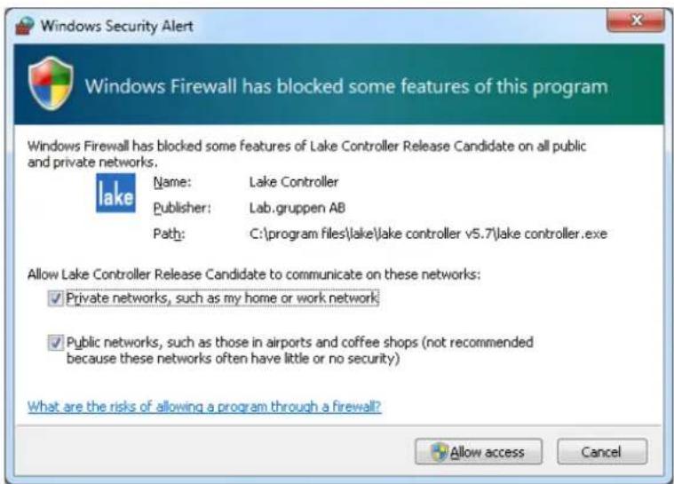
Figure 3-2: Standard Windows Firewall Security Alert
When using the standard Windows 7 firewall and an alert similar to that shown in Figure 3-2 is displayed:
- Select checkboxes to allow the Lake Controller (or other Lake application) to access both the Private and Public networks.
- Tap Allow Access.
When the Lake Controller or other Lake application opens without this warning, but connected Frames cannot be identified on the network, the application firewall settings can be verified manually:
- Type "firewall" into the Windows 7 search feature as shown in Figure 3-3.
- Select "Allow a program through Windows Firewall" from the list of Control Panel options.
- Tap Change Settings and locate the Lake application in the list.
- Ensure all checkboxes are marked then tap OK.

Figure 3-3: Allow a Program through Windows Firewall (via Win 7 Search)
3.3 IP Address Configuration
The network card of the host computer running the Lake Controller must have a valid IP address to communicate with Lake devices on the network.
By default, Windows computers are configured to obtain an IP address automatically. This default setup works successfully for most configurations and is the recommended starting point. On an unmanaged network this option will allocate the PC an IP address from the range 169.254.x.x.
If using automatic IP address allocation, please ensure your Ethernet switch and/or Lake devices are turned on and connected to your PC for a minute or so (Windows XP - generally faster on Windows 7) before starting the Lake Controller. This allows Windows time to correctly identify your PC's IP address, and therefore allows the Lake Controller to communicate properly when it scans the network.
If you are on a managed network (such as a corporate network) with a DHCP server and you are having communication problems, it is recommended that you change the IP addressing mode on the devices to use DHCP. Please consult a network specialist if you have trouble with complex network configurations.
A fixed IP address is useful if you are frequently switching between network adapters, or unplugging and reconnecting your network cable. The automatic IP address allocation used by Windows requires a valid network to be present, and can take up to one minute for the PC to discover its IP address. In this case it is recommended that you try using a fixed IP address in the same subnet as that used by default address allocation (i.e. 169.254), but using the reserved ranges of either 169.254.0.x or 169.254.255.x.

The IP address ranges 169.254.0.x and 169.254.255.x are reserved by IANA so future use of these address ranges cannot be guaranteed.
You can specify a fixed IP address by following these steps in Windows 7:
- Tap the Windows Start icon, type "network" in the search bar then tap NETWORK AND SHARING CENTER from the options listed under the Control Panel heading as shown in Figure 3-4.

Figure 3-4: Opening Windows Network and Sharing Center
- Select the appropriate network connection (Local Area Connection or Wireless Network Connection) to configure, then select "Change settings of this connection" as shown in Figure 3-5.
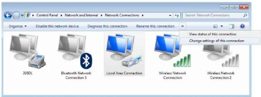
Figure 3-5: Selecting Wired Network Connection

Although this tutorial uses Local Area Connection as an example, the principles also apply to Wireless Network Connection.
- Select INTERNET PROTOCOL VERSION 4 (TCP/IPV4), and tap the PROPERTIES button.

Figure 3-6: Local Area Connection Properties
- Select "Use the following IP address," enter an IP address, tap TAB or tap in the Subnet mask box to auto-populate with the correct mask.

Figure 3-7: TCP/IPv4 Properties
- Tap OK to apply changes, and exit Internet Protocol (TCP/IP) Properties.
- Tap OK to apply changes, and exit Local Area Connection Properties.

Please refer to Chapter 29 for more information on the selection of an appropriate IP address.
3.4 Wired Network Setup
3.4.1 Overview
The Lake Controller host computer can be connected directly to any Lake device through the Ethernet connectors. Multiple devices can be connected by cascading connections between units, although this is not a recommended solution for the successful use of Dante™ (Digital Audio Networking via Ethernet). Connecting devices via a good quality external Ethernet switch with QoS is highly recommended. Please refer to tutorial section 4.3.6 for further information regarding Dante, and section 3.6.4 for details on using QoS with Dante.
The Lake Controller can be connected to a network of Lake devices using a wired or wireless Ethernet solution. A wired network is a simpler, faster and more robust solution and should be implemented where possible in preference to using a wireless system. Additionally, when implementing Dante audio networking in conjunction with a wireless access point for Lake Controller data, additional configuration of an external
Ethernet switch is required to filter Dante audio traffic from reaching the access point. Please refer to section 3.6.3.
The Controller can connect anywhere on a network of Lake devices. LEDs next to each port flash to confirm valid communication. Please connect the Controller computer to the network with an Ethernet cable, and follow the verification steps in the next section.
3.4.2 Verifying Wired Controller and Device Communication
Once the network is connected, follow these steps to confirm communication between the Lake Controller and Lake devices:
- Double-tap the Lake Controller shortcut icon from the Windows desktop. The SELECT NETWORK Adapter dialog box (shown) appears if your computer has more than one network interface enabled. This typically occurs if your PC has both wired and wireless network interfaces.

Only one network adapter should be enabled on your PC when using the Lake Controller. Network adapters can be disabled via the Windows Network and Sharing Center > Change Adapter Settings.
- Select the Ethernet adapter currently used for the network (the wired adapter for this example).

Figure 3-8: Select Network Adapter
When the Controller begins, you will be prompted with a dialog box asking whether to load the last configuration.
- Tap NO to this dialog. The Main page of the Controller is displayed.
- To verify that the devices are on the network and communicating, tap the Modules button. The Module scroll bar will be displayed.

Figure 3-9: Module Scroll Bar
The folder to the left of the Module scroll bar provides Virtual Frames, which are always available whether or not the network is connected. Virtual Frames allow you to create a complete system configuration offline.
If your network connections are valid, all devices connected to the network appear on the Module scroll bar to the right of the Virtual Frames.
Figure 3-9 shows the Module scroll bar, which visually identifies the number of Modules within each Frame on the network. The number of Modules within a Frame depends on the device type/configuration. Modules shown with a circle are available on the network, but not currently in use; Modules identified with text only are already in use in the current system configuration. Please refer to the tutorial in chapter 4 for more information on Modules and Frames.
3.5 Wireless Network Setup
3.5.1 Overview
Several hardware manufacturers supply wireless networking solutions that adhere to the various 802.11 wireless Ethernet standards. This means that any standard Ethernet 802.11 wireless networking solution should work with this network system.
When using a wireless access point on the same network as Dante digital audio, an approved external Ethernet switch must be configured to filter Dante audio packets from reaching the wireless network. Please refer to section 3.6.3 for further information.
An access point is used in a wireless Ethernet network configuration to connect Lake devices to the Lake Controller host computer. The access point is connected to the wired network using standard Ethernet cables. It performs the same function as a switch: receiving, buffering, and transmitting data between wired and wireless networks.
![graph LR A["Lake Processors"] --> B["ACCESS POINT"] B --> C["TABLET PC"] style A fill:#f9f,stroke:#333 style B fill:#ccf,stroke:#333 style C fill:#cff,stroke:#333](/content/2026/07/1419186/images/f64ec4e81366238a85a8aef93020cda6885f45dfb2ec49201821fc9a0490c7dc.jpg)
Figure 3-10: Basic Wireless Setup (Not Suitable for Use with Dante or larger networks)
Ideally, the procedure just described yields a perfectly functional and secure system. However, there are two complications: Some environments have additional wireless network systems and communications equipment competing for the same airspace used by the Lake system. It is also important to provide security so another wireless network cannot access this network system.
As part of the 802.11 standard, various levels of access control and encryption exist. There are also different communication channels that operate at different frequencies.
The service set identifier (SSID) controls access to this wireless network by functioning as a password or key between wireless network devices to differentiate them from each other. The SSID must be exactly the same on all wireless devices (the access point and all Controller host computers). The SSID is case sensitive.
Although the SSID differentiates among wireless systems, it does not provide security to the network. Wired Equivalent Privacy (WEP) is a security protocol for wireless networks defined in the 802.11 standard. The WEP protocol provides the same level of security as a wired network by encrypting data over radio waves to protect it during transmission. It is recommended that WEP encryption is enabled if other computers are connected to your Ethernet network.
3.5.2 Configuring the Tablet PC for Wireless Networking
Assuming that the wireless access point has been set up appropriately and is turned on, we now need to configure the Tablet PC to connect to this access point.
- Navigate to the Windows Network and Sharing Center as shown in Figure 3-4.
- Tap the wireless signal strength icon at the bottom-right of the screen in the Windows notifications area and select the wireless access point from the list that appears and tap CONNECT as shown in Figure 3-11.

Figure 3-11: Connecting to a wireless access point
- Enter the network security key, or press the button on the wireless access point if requested.
- If you encounter network problems when using the default automatic IP address allocation (more likely with Windows XP), please set up a fixed IP address as described in section 3.3.

Please refer to chapter 29 for more information on the selection of an appropriate IP address.
3.5.3 Confirming Wireless Operation of the Lake Controller
To confirm wireless operation:
- Double-tap the LAKE CONTROLLER icon to start the software. If you have more than one network adapter enabled, the SELECT NETWORK ADAPTER dialog box will be displayed; select the WIRELESS NETWORK ADAPTER.
- Tap NO when asked whether to recall the last configuration. A brief resync message will appear for each Lake device on your network, confirming that your network connection is operating properly.
- Tap MODULES. Each online device is represented on the Module scroll bar by a number of Module icons surrounded by a border.
- Tap QUIT CONTROLLER to exit.
3.6 Dante and AES67 Digital Audio Networking
Dante and AES67 provide multi-channel digital audio networking over a standard Ethernet network, alongside control data for the Lake network. Various topics relating to network configuration are summarized in this section; for further details please refer to associated Dante literature available via:
Start > All Programs > Lake Controller vX.X > Documentation > Dante Documentation after installing the Lake Controller software.
Additional Dante product information is available at the Audinate website: http://www.audinate.com/
AES67 is a new open standard making it possible to connect more devices together and share audio.
3.6.1 Dante Controller Compatibility
All devices are compatible with Audinate's Dante Controller software (not applicable for MY8-LAKE). AES67 configuration for AES67-enabled devices is also done in Dante Controller.
Changes made via the Lake Controller will be reflected in the Dante Controller and vice-versa:
When both the Lake Controller and Dante are active, changes will synchronize immediately across both software controllers and affected devices. When Dante-related parameters are changed via the Lake Controller while the Dante Controller is disconnected or closed, the Dante Controller will inherit the change the next time it is connected or opened. When Dante-related parameters are changed via the Dante Controller while the Lake Controller is disconnected or closed, the Lake Controller will identify the Frames as Out of Sync the next time it is connected, or opened using the Recall Last System Configuration option.
3.6.2 Dual Redundant Network Configuration
With dual redundancy activated, the Controller can be connected to the secondary network connection using an IP address in the range 172.31.x.x. on the Lake Controller computer. This configuration allows for fail-over to the secondary network should a problem occur with the primary network. AES67 audio can only be transmitted and received on the Primary network. For PLM+ and D Series devices, it is also possible to manually configure the IP Configuration for the secondary network via Lake Controller Technical Data.

Do not connect Controllers to the primary and secondary network connections simultaneously.
3.6.3 Using Dante with Wireless Data Control or Low-Bandwidth Devices
Dante (Digital Audio Networking) technology requires a reliable 100 Mbps (or faster) network to operate, and therefore cannot operate via a wireless transmitter/receiver. However, in most Lake networks, it is likely that wireless control of the Lake devices will be required on the same network that is transmitting and receiving Dante digital audio signals.
To achieve this, you must configure the Ethernet switch on the boundary of the wireless network to filter Dante traffic from reaching the wireless access point or other lower bandwidth devices (e.g., legacy devices such as the Contour Pro 26 or Mesa Quad EQ), or you will most likely experience communication problems.
The diagram below summarizes the desired outcome from correctly configuring your Ethernet switch to filter Dante audio packets.
![graph TD A["Dante Device"] -->|Multicast Audio| B["Linksys SRW224G4"] C["Dante Audio Network"] -->|Multicast Audio| B B -->|Higher Latency (wireless) or Lower Bandwidth Networks| D["Low Bandwidth Device"] B -->|Multicast Audio| E["Router"] style A fill:#ccc,stroke:#333 style C fill:#ccc,stroke:#333…](/content/2026/07/1419186/images/129892f619dd0ecd16cc3774fa14fec281f0978256ad44f7711d63638fdb44b8.jpg)
Figure 3-12: Using Dante with Low Bandwidth devices
Please refer to the Audinate® document AUD-ANO-ACL Filtering SRW224G4 for further details regarding ACL packet filtering. This document is available via:
Start > All Programs > Lake Controller vX.X > Documentation > Dante Documentation after installing the Lake Controller software.
Additional Dante product information is available at the Audinate website: http://www.audinate.com/
3.6.4 Dante with Quality of Service Ethernet Switches
The use of an external Ethernet switch with QoS (Quality of Service) is strongly recommended when using Dante digital audio over your Lake network. Dante uses standard network QoS techniques available in off-the-shelf Ethernet switches to prioritize clocking and audio traffic, and to allow non-Dante devices such as personal computers to share a single network with Dante devices. The diagram below shows the order of priority given to the different types of data packets going through the switch. Using a switch without QoS, or with QoS turned off on a busy network, may result in audio packets arriving too late to be played out, resulting in audio glitches.
![graph TD A["PC generating network traffic"] --> B["Dante Audio Device"] B --> C["Dante Control Device"] C --> D["Dante Audio Device"] D --> E["Network with mixed devices and traffic types"] style A fill:#f9f,stroke:#333 style B fill:#ccf,stroke:#333 style C fill:#cfc,stroke:#333 style D fill:#fcc,st…](/content/2026/07/1419186/images/968a8baf7923ec93af5fe0a2b4311959ae1528f6afcc88b0ae0f7623125fb6a1.jpg)
Figure 3-13: Dante Quality of Service Switch Configuration
Please refer to the Audinate document AUD-ANO-QoS Switch Configuration for further details regarding ACL packet filtering. This document is available via:
Start > All Programs > Lake Controller vX.X > Documentation > Dante Documentation after installing the Lake Controller software.
Additional Dante product information is available at the Audinate website: http://www.audinate.com/
3.6.5 Recommended Network Topologies When Using Dante
The use of an external Ethernet 100 Mbps switch with QoS (Quality of Service) is highly recommended. It is also recommended that each device has its own direct connection to that switch. Where switches are connected together, this should be achieved via a gigabit fiber or copper connection.
![graph TD A["Device 1"] -->|100Mbit/s links| B["Gigabit Inter-switch links (Copper or Fiber)"] C["Device 2"] -->|100Mbit/s links| B D["Device 3"] -->|100Mbit/s links| B E["Device 4"] -->|100Mbit/s links| B F["Device 5"] -->|100Mbit/s links| B G["Device 6"] -->|100Mbit/s links| B](/content/2026/07/1419186/images/8df192a5d1c99970b3a03e362eea97079372973971cf96d9fe5029e0332a1ddb.jpg)
Figure 3-14: Recommended Network Topologies
Two Lake devices may be daisy chained together and run Dante. The recommended latency when connecting two Lake devices in this manner is 0.8 ms.

Figure 3-15: Only two Lake devices may be daisy chained for use with Dante
More than two Lake devices should not be daisy chained together when Dante is being used.
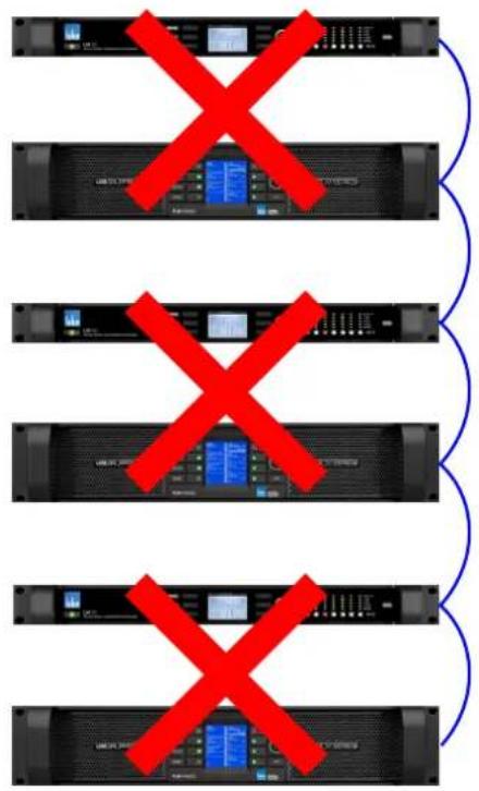
Figure 3-16: Do not daisy chain more than two Lake devices when using Dante
The use of Dante across wireless networks as shown below is not supported.
![graph LR A["User Interface"] --> B["X"] B --> C["X"] C --> D["X"] D --> E["X"] E --> F["Server Interface"]](/content/2026/07/1419186/images/e216793608f8cdd54d13f773e894acd651650b623f5b957b16d84d98d9f5a50a.jpg)
Figure 3-17: Do not use Dante across wireless networks
Please refer to the Audinate document AUD-ANO-QoS Recommended Network Topologies for further details regarding ACL packet filtering.
This document is available via:
Start > All Programs > Lake Controller vX.X > Documentation > Dante Documentation after installing the Lake Controller software.
Additional Dante product information is available at the Audinate website: http://www.audinate.com/
4. Lake Controller Tutorial
This tutorial will help you start using the Lake Controller software quickly and easily by providing an overview of common features. There are many underlying details not covered in this tutorial, so please refer to the other sections of this manual for detailed reference information.
The tutorial uses the Lake LM 26 (Contour Mode) & LM 44 (Mesa Mode) these are the two main types of Modules that are available across Lake-enabled devices. You may however follow this tutorial with any product; most features and functionality are common across all products.
4.1 Starting the Lake Controller
To start the Lake Controller:
- Double-tap the Lake Controller software icon located on the Microsoft® Windows® desktop.
- Tap NO in the dialog box asking if you would like to recall the last configuration.

Tapping YES recalls the configuration in use prior to exiting the last Lake Controller session. A comparison occurs and any differences are highlighted for online Modules. Audio processing is not affected.
The Main page appears and is in its default, blank state.
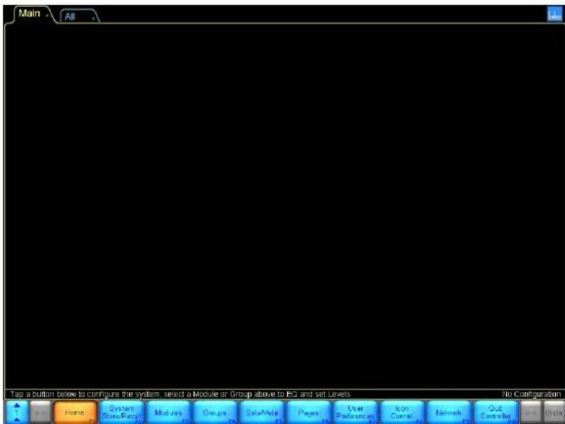
Figure 4-1: Main Lake Controller HOME Page
4.2 Overview of Main Page Components
This section covers the various components shown on the main page.
4.2.1 Button Bar Interface
The button bar, located at the bottom of every page in the software, is used to navigate through and activate the Lake Controller features and functions. Three colors indicate the button status:
▶ ORANGE - currently selected menu or function BLUE - available menu or function based on current selection - GRAY - currently unavailable menu or function
Figure 4-2: Context, Scroll and HOME Buttons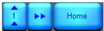
The button with the numbered arrows pointing upward shown in Figure 4-2 is the CONTEXT button, which enables fast system navigation. Contexts allow you to jump directly from one view to another view without having to use the tool bar for navigation. For further detail, please refer to section 13.1.
The button with arrows pointing right is active when a page or menu scroll bar contains more information than can be displayed on the width of the screen. Tap this button to move the scroll bar, pages, or overlay tabs to the right, revealing additional data.
The HOME button is available from almost all menu levels, and returns you to the Main page of the system.
Figure 4-3: Scroll and Undo Buttons
The scroll and undo buttons shown in Figure 4-3 are available on the right side of the button bar and may be active or inactive depending on the screen being viewed. The button with arrows pointing left moves the scroll bar, pages, or overlay tabs to the left.
The button labeled UNDO (or REDO after UNDO has been used) provides a single-level UNDO/REDO function for adjustments made to EQ/levels and crossovers (where applicable).
Generally, labels on buttons describe the open submenu or the function performed by tapping the button.
4.2.2 Help and Status Messages
Context-sensitive help is displayed above the button bar on the left.

Figure 4-4: Context Level Help
System status messages are displayed above the button bar on the right. In the following example, the network status is shown to be offline.

Figure 4-5: Network Status Messages
4.2.3 Page Tabs
At the top left of the user interface, the MAIN and ALL pages are presented. The MAIN page is the default page ready to use. The ALL page provides monitoring of up to 260 Modules on a 1,024 × 768 pixel screen without scrolling. It displays a status summary for each Module, with additional status information for Lab.gruppen amplifiers. More pages can be added as required to logically partition your system.

Figure 4-6: Example Page Tabs
For further details, please refer to section 8.7.
4.2.4 Global Input Router Priority Control
If enabled, the Global Input Router Priority Control (formally known as "Digswitch") makes it possible to control all input routers in the system. LM Mesa Mode devices can be excluded from this control via the separate option from the Global Control tab.
The function is to instantly switch between input router priority Force 1, 2, 3 or 4, or set to Autoselect. It is also possible to check the current status of all input routers in all frames in the system via the magnifying glass.
The Force options:
[Prio 1] forces all online devices in the current system configuration to use forced priority 1 input for all input routers. Prio 2, 3 and 4 work the same way for the associated input priorities.
Autoselect:
[Auto] sets all input routers to AUTOSELECT priority selection.
[Alert] can be used in conjunction with Auto. When Alert is enabled, an "Input Prio Drop" warning is displayed on the module and it will display the GSI (Global Status Indicator) warning if not all input routers for that device are using Prio1 in the input routers. This way it is easy to see if one or more devices have changed to a lower prioritized input.
[Magnifying glass] displays a matrix of all input router statuses for all frames (not including LM if excluded) in the current system configuration. Each cell is clickable and will then display the FrameLabel of the device(s) with input routers in that specific cell.
Figure 4-7: Prio button

Figure 4-8: Prio button expanded
4.2.5 Minimizing the Lake Controller
To minimize the Lake Controller software and return to Windows, tap the Lake icon in the top-right corner of any screen. When running in Windowed-mode, minimize the controller using the standard Windows minimize button.
Figure 4-9: Use the Lake logo (top right of screen) to minimize the Lake Controller
This icon is animated. It rotates when the software is performing any function that requires the user to wait for data to be transferred or for a processing to complete.
4.3 Modules and Frames
4.3.1 Overview
A Frame represents one physical Lake device on the network. Multiple Modules are contained within each Frame. The number of Modules available for a given device is dependent upon the signal processing configuration/capabilities of the device.
| PRODUCT CONFIGURATION NUMBER OF MODULES | ||
| D 200:4L 4x4 Power Amplifier 4 Contour Modules | ||
| D 120:4L 4x4 Power Amplifier 4 Contour Modules | ||
| D 80:4L 4x4 Power Amplifier 4 Contour Modules | ||
| D 40:4L 4x4 Power Amplifier 4 Contour Modules | ||
| D 20:4L 4x4 Power Amplifier 4 Contour Modules | ||
| D 10:4L 4x4 Power Amplifier 4 Contour Modules | ||
| PLM+ 20K44 4x4 Power Amplifier 4 Contour Modules | ||
| PLM+ 12K44 | 4x4 Power Amplifier | 4 Contour Modules |
| PLM+ 5K44 | 4x4 Power Amplifier | 4 Contour Modules |
| PLM 20000Q | 2x4 Power Amplifier | 2 Contour Modules |
| PLM 14000 | 2x2 Power Amplifier | 2 Contour Modules |
| PLM 10000Q | 2x4 Power Amplifier | 2 Contour Modules |
| Lake LM 26 | 2x6 Loudspeaker Processor | 2 Contour Modules |
| 4x4 System Equalizer | 4 Mesa Modules | |
| Lake LM 44 | 4x4 System Equalizer | 4 Mesa Modules |
| 2x6 Loudspeaker Processor | 2 Contour Modules | |
| MY8-LAKE | 4x12 Loudspeaker Processor | 4 Contour Modules |
| 8x8 System Equalizer | 8 Mesa Modules | |
| 2x6 Loudspeaker Processor + 4x4 System Equalizer | 2 Contour Modules + 4 Mesa Modules | |
Table 4-1: Overview of Lake Devices and Module Configurations
Figure 4-10 shows the Module scroll bar displaying Virtual Frames for Lake-enabled devices, after accessing the Virtual Frame folder.

Figure 4-10: Module Scroll bar
Figure 4-11 shows the Module scroll bar displaying Virtual Frames for Lake-enabled devices, after accessing the Virtual Frame folder.
Figure 4-11: Module Scroll bar - Virtual Frames
To place an online Frame in the work area for use during this tutorial:
- Tap the Module button to display the Module scroll bar as shown in Figure 4-11.
- Tap one of the gray circles (which indicates an available online Frame). The cursor takes on the form of the selected frame.
- Place the selected Frame in the work area by tapping in the required location.
An LM 26 (Contour Mode) and an LM 44 (Mesa Mode) are used for most examples in this tutorial; the resulting screen will look similar to that shown in Figure 4-12, depending on the product you are using.

Figure 4-12: LM 26 Frame Placed in Main Work area
4.3.2 Module Icons
Each Module icon provides configuration information as shown in Figure 4-13.

Figure 4-13: Module Icon Components
Module ID - Identifies a particular Module within the device, represented by this icon. Frame Label - Identifies the Frame (device) associated with this icon by a user-defined label that also appears on the front panel of the device. Module Type - For Contour modules, this identifies the number of output channels of the module. For Classic and Aux modules it will only state the number of outputs, and for the other module types it will state XP, FIR or LP before the number of channels. MEq is for Mesa EQ Module. Module Label - User-defined label that describes the Module's use or speaker type. Module Selection and Clip Indicator - The Module icon border is yellow to indicate the Module is selected. If it flashes red, a channel on that Module is clipping.
Power Output Mute Indicator (Lake-enabled amplifiers only) - A red bar indicates the power output channel is muted; a blue bar indicates it is unmuted. This indicator appears on the Module from where the channel is routed. Input Mute Indicator - If the central round part of the icon is red, the input is muted; if the icon is blue, the input is not muted. ▶ Output Mute Indicators - Displayed as small red bars when the outputs are muted and are absent if unmuted. The number of mute indicators depends on the number of output channels in the selected Module type. Module Label - Displays the label for the Module, in this case a default Classic 3-Way. The Module label is by default changed to the name of the Module file recalled, but with use of Dynamic Module Label this behavior can be changed depending of the need. For further details on Module label abbreviations, Dynamic Module Label, and an explanation on Module types, please refer to chapter 9.
4.3.3 Selecting and Moving Icons
Multiple icons may be selected (via the MODULES, GROUPS, PAGES, and ICON CONTROL menus), providing a faster solution to Graphical arrangement of the work area. For example, multiple icons can be dragged back to the scroll bar, moved around on screen, or dragged to another page tab. In addition, the icon meters can be enabled/disabled or icon size can be modified.
This example uses an LM 26 (Contour Mode) and an LM 44 (Mesa Mode) for demonstration purposes; the logic remains the same for all types of Group, Module, and Super Module icons.
- Drag a box around the icons you wish to move.
![graph TD A["LM 26\n5 CL9way"] --> B["CL9way"] C["LM 26\n3"] --> D["CL9way"] E["LM 44 MEQ"] --> F["Mega EQ"] G["LM 44 MEQ"] --> H["Mega EQ"] I["LM 44 MEQ"] --> J["Mega EQ"] K["LM 44 MEQ"] --> L["Mega EQ"]](/content/2026/07/1419186/images/85964e200d2d6554ca50b7543fab18cebf168a994e719196be174472ce630500.jpg)
Figure 4-14: Click and drag around Module icons
- Release the pen (or mouse); icons inside the yellow rectangle are now selected.
![graph TD A["LM26 3 CL8ray"] --> B["LM26 3 CL8ray"] C["A LM44 MEs Mesa EQ"] --> D["B LM44 MEs Mesa EQ"] E["C LM44 MEs Mesa EQ"] --> F["D LM44 MEs Mesa EQ"]](/content/2026/07/1419186/images/a72cc0d44cb58242e19e4217682bf27466bf42b549de7b354db6d514c4bf9ca5.jpg)
Figure 4-15: Yellow border snaps to selected Module icons
- Tap inside the yellow box, and drag it to the new area.

Figure 4-16: Dragging multiple Module icons
- Release the pen (or mouse); the icons are now deselected.

Figure 4-17: Release to deselect Module icons
To drag icons to a new page, select the icons you wish to move and then drag them over the page's tab at the top. That page will be automatically selected. You may then place the icons where required.
4.3.4 Labeling Frames and Modules
The Frame label initially shows the product code (e.g. 10000Q) which varies depending on the device. The Frame label is the same on all Modules in the Lake Controller, and on the front panel of the associated device. The Frame label helps to identify the physical location of a device on the network.
To label a Frame:
- Tap the A Module to select it.
A yellow border surrounding the Module icon indicates it is selected.

If a Module is not selected, most of the button bar functions are gray to signify they are inactive.
- Tap LABEL & LOCK.
- Tap LABEL FRAME to display the on-screen keyboard.
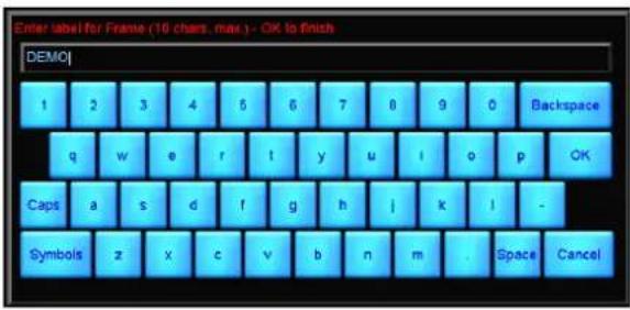
Figure 4-18: On-screen keyboard
- Type 'Demo' using the on-screen (or external) keyboard, and tap OK. The Frame label field for the Frame's Modules displays 'Demo'.
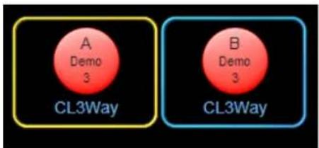
Figure 4-19: Changing the Frame Label
Now let's assign a name to the A Module:
- Tap the A Module to select it.
- Select LABEL MODULE from the button bar.
- Tap LABEL EXIT to return to the MODULES menu.
- Name this Module 'My 3-Way' using the on-screen keyboard, and tap OK.

Figure 4-20: Labelling a Module

To label a Super Module, select it in the work area and tap LABEL SUPERMOD.
4.3.5 I/O Config

This section assumes the use of classic routing mode; all providing extensive I/O routing options. The MY8-LAKE in simplified view provides a fixed output config.
- Tap the I/O CONFIG button to display the block diagrams of each Module in the Frame.

Figure 4-21: LM 44 I/O Configuration Screen with Input Configuration Summary enabled
The right side of the I/O CONFIG page can be dragged to scroll up and down for viewing of all Module block diagrams where all diagrams cannot fit on the screen.
- Tap any black space within the block diagram area and drag up or down to scroll. The I/O CONFIG page is interactive; each blue processing block can be selected to directly access the relevant screen in the software. Each block diagram has a front-end input mixer.
- Tap any one of the four inputs of the 'My 3-Way' Module to access the input mixer.

Figure 4-22: Four-Channel Input Mixer
The number of inputs preset in the input mixer is relevant to the number of inputs available simultaneously for the device / module combination, and allows the inputs to be selected or mixed together appropriately.
- Tap the exit button is the bottom-right corner of the Input Mixer pop-up window to return to the I/O CONFIG screen.
Each output can be custom configured by the user. Tap one of the zoom icons (represented by a magnifying glass) on the right side of the Module's block diagram. This action will open the Output Configuration window.

Figure 4-23: LM 26 Output Configuration
The Output Configuration window provides the ability to route any physical input or Module output to any available analog or digital output on the device. The arrows below the source and destination labels allow selection and mapping of all available I/O.
LM Series devices provide the ability to route any of the eight Input Router Outputs directly to any output. This allows fail-over input switching to be configured for pass-thru / format conversion purposes. For instance, an input router can be configured for fail-over to Analog if AES input fails, and whichever audio is used can be passed through to Dante (or any other output type). For further information, please refer to section 21.1.
- Tap the blue EXIT/RETURN button in the bottom right to return to the I/O CONFIG page.
The left side of the I/O CONFIG summary screen provides both clock and INPUT CONFIGURATION functions along with other Frame specific functionality. Status information is provided, and zoom icons open pop-up windows for access to configuration parameters.
Lake devices have sophisticated digital clocking systems, allowing selection between internal and external clock sources at all standard audio sample rates. By default, all Lake devices (except the MY8-LAKE) use
an internal clock operating at 96 kHz. You can choose to use any available external clock source using the interface provided by the clock source configuration window.
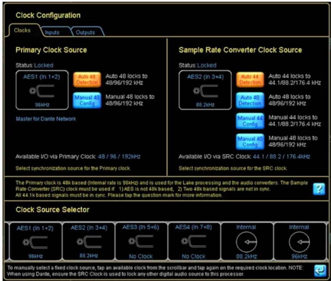
Figure 4-24: LM 44 Digital Clock Configuration
The current Primary Clock Source is shown on the top left of the screen, and the current Sample Rate Converter Clock Source is shown on the top right. You can choose any available clock source using the Clock Source Selector scroll bar at the bottom of this window. The Inputs/Outputs tab is available on some products providing quick access to set unique digital clocks for specific inputs and outputs.
Please refer to each product's Operational manual for further details on clocks, clock source priorities, sample-rate converters, and signal processing latency of the product.
The INPUT CONFIGURATION pop-out window allows flexible routing of all available inputs to each Input Mixer channel along with a four-level auto-select priority allocation for each input, as shown in Figure 4-25.
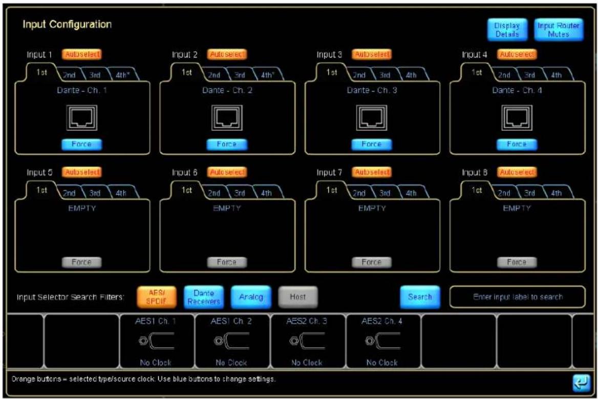
Figure 4-25: LM 44 Input Configuration Screen
From this interface, you can allocate which input is used for each input channel of the Input Mixer, and in which order up to four inputs should auto-select (fail over) for each input channel.
The input AUTOSELECT feature allows you to set up a redundant system. The device will attempt to use the first signal; if the first signal is unavailable it will try the second, third, and fourth signals.
Tapping DISPLAY DETAILS allows control of digital clock selection/digital gain offsets and analog input headroom as shown in Figure 4-26.
DIGITAL GAIN OFFSET allows fine-tuning of gain between different digital and analog signals to allow for a seamless transition between the signal sources.

Figure 4-26: LM 44 Input Configuration - Details View
The next summary item on the left side of the I/O CONFIG screen (LM Series devices only) is GPIO Configuration. Tapping this icon, or the summary text, will display the screen shown in Figure 4-27.
![graph TD A["Acting on"] --> B["Action when transition to CLOSED"] B --> C["Action when transition to OPEN"] C --> D["Current state"] E["No Action"] --> F["-"] G["No Action"] --> H["-"] I["OPEN"] --> J["OPEN"]](/content/2026/07/1419186/images/e19c69d2c7fc2c1934f9e08673988d568d0c02c232b1f825715e0a5bde4b26df.jpg)
Figure 4-27: GPIO Configuration (LM Series Devices Only)
GPIO Configuration is used to set the actions for this contact-closure style external control interface. For further details, please refer to the LM Series Operation Manual and to section 8.2.3 in this document.
The last item on the left side of the I/O CONFIG page allows remote control of Iso-Float™. This powerful feature allows you to troubleshoot grounding issues remotely from the Controller.

Figure 4-28: Analog Iso-Float Status Screen
The ANALOG ISO-FLOAT STATUS window shows you the current state of the device hardware and allows you to make changes to the grounding state of each analog converter card.
After closing the ANALOG ISO-FLOAT STATUS pop-up window, return to the Main page by tapping the HOME button.
4.3.6 Dante
Dante audio networking technology from Audinate provides a hassle-free digital audio networking solution for Dante-enabled Lake devices providing reliable, sample-accurate, low-latency audio distribution over Ethernet.
Dante provides a reliable, digital-audio networking system with complete flexibility, ease of use, and cost-effectiveness. With innovative features such as Zen™, Dante-enabled Lake devices automatically find each other and also allow any Dante audio channel on the network to be routed to the input of one or more devices.
Dante can be easily integrated into an existing network, sharing the system with normal data traffic. Dante also offers a virtual sound card feature for audio recording, processing or playback using computer-based programs. This feature is enabled by plugging into the standard Ethernet port on a PC; no external boxes or sound cards are required.
On Dante-enabled Lake devices no additional hardware is required; a single Ethernet connection can transmit all audio and control data. Table 8-3 on page 140 summarizes the number of Dante input and output channels per Lake product, along with an indication of whether the product provides dual redundant Dante audio networking which as described in section 3.6.2, and the associated Product Operation manuals. Some Dante-enabled Lake products also support AES67. For these products the Dante Configuration view is named "Dante and AES67 Configuration".

The Audinate services 'Dante ConMon' and 'Dante Discovery' must be running to enable Dante configuration from the Lake Controller; restart these services if Dante-related problems persist.
4.3.7 Levels and Meters
From the Main page, tap the My 3-Way Module icon to display its parameters. This action will enter the EQ and Levels interface for the Module, displaying the EQ screen the first time it is accessed.
Tap the LEVELS tab at the top left of the display to access the LEVELS interface. This provides metering information and faders for adjustment of gains, delays, and limiters.
By default, gain controls and meters are displayed for the input and all outputs of the Module. Mute controls are located below each input and output meter, with a polarity button for the input.
![EQ Demo - My 3-Way. MODULE: +1.00 dB [0.00] 0.00 dB. Reverting Volumes (dB) [0.00] 0.00 dB. Reverting Max - Max1 [0.00] 0.00 dB. Reverting Max - Max2 [0.00] 0.00 dB. Gain Gain Gain Gain Gain. Input Mutes Input Mutes Events & Control. Input Mixer.](/content/2026/07/1419186/images/0050dbd866cb83bdda83dfe6991fe210e819b99cfa1bec9cba2a8ab85e3fb225.jpg)
Figure 4-29: Levels Screen
To unmute the Module input, tap the red mute button labeled Input MUTED.

The Module input mute button controls the post input mixer signal mute. To adjust levels of each physical input, tap the Input Mixer button below the Module Input Mute button.
4.3.7.1 Adjusting Levels
There are three ways to adjust the gain of an input or output:
▶ Make large changes (1 dB increments) by tapping and sliding the fader. ▶ Make small adjustments (0.1 dB increments) by tapping and dragging above, below, or to the left of each fader control. Adjust the gain to an exact value (0.01 dB increments) by tapping the gain value directly and using the on-screen keyboard to enter the new value as follows:
- Tap the input gain value (highlighted in blue at the top left of the screen).
- Enter -3.75 dB of gain, and tap OK.
Figure 4-30: Using the parameter edit function to enter values
The same principles apply to adjusting other levels (delays, limiters, and so on) throughout the Lake Controller software.
To view/update other types of levels, simply tap the required type of level from the button bar (Delay, Limiter Max RMS, and so on). The faders and levels change to display the value of the selected level type.
4.3.72 Metering
In the Levels interface, all input and output levels are accompanied by metering. Input meters show both average level and peak level, with a user-definable peak hold. Output meters show the aforementioned level metering on the left side of the meter face, and additionally show limiter activity on the right side of the meter face.

Regardless of the level type currently being adjusted, gain and limiter metering is always displayed.
If an audio channel is clipped, the meter face turns red. Additionally, if an audio channel is within 2 dB of clipping, the meter face turns orange.

Figure 4-31: Clipping and -2 dB warning indicators
As limiters are engaged, the amount of gain reduction is shown with a meter operating in the downward direction.

Figure 4-32: Orange downward meters indicate channel limiting
The limiter meter displays the total amount of limiting resulting from both peak and RMS limiter functions of the LimiterMax™ loudspeaker protection system.
4.4 Equalization
From the LEVELS interface, tap the EQ tab in the top-left corner of the display to move to the EQ controls for the Module. Parametric EQ (PEQ) is displayed by default.
![graph LR A["Levels"] --> B["XOVER"] B --> C["PEQ1"] C --> D["BLEQ2"] E["Frequency Lock"] --> F["A/B"] G["Blue Signal"] --> H["Blue Signal"] I["Blue Signal"] --> J["Blue Signal"]](/content/2026/07/1419186/images/c0eabd7572a1a767650395ce113fb964930e75f718c1d0e6b01c1aba7e6d6a18.jpg)
Figure 4-33: PEQ tab with EQ filter tools and options
Multiple EQ overlays are identified by tabs at the top left of the display. A three-way Module initially has one Parametric (PEQ1) and one Band Level (BLEQ2) overlay, in addition to the XOVER tab. A Mesa EQ Module has a tab labeled HPF/LPF instead of XOVER.
The Parametric EQ overlay (PEQ) provides low-shelf, parametric, Mesa, and high-shelf filters. The Band Level EQ overlay (BLEQ) enables the creation and adjustment of linked filter bands. The XOVER screen allows selection and adjustment of crossover filters, in addition to output EQ.
4.4.1 EQ Overlay Store/Recall
EQ Overlays can be stored and recalled, either to an existing EQ Overlay which will replace the current EQ Overlay content or by Recall as New to add an additional EQ Overlay. All types of EQ Overlays can be stored and recalled to and from Modules and Groups.
When an EQ Overlay is stored or recalled, the path to where it was stored or recalled from is stored by the Module or Group. The path is relative the Modules and EQ Overlay folder, so it will function correctly for migrated files (i.e. the path information will always resolve to the My Documents > Lake Controller folder relevant for the software version after upgrade). If an EQ Overlay file is stored outside the Modules and EQ Overlay folder, the path will not be stored in the Module for that Overlay.
The paths for different EQ Overlays in Modules and Groups are also stored in the System file, however the path is not stored in the frame. E.g. Recalling settings through a FramePreset recall, for dragging frames from scrollbar to the main workarea will not contain path information for EQ Overlays.
4.4.2 Graphic EQ
By default a Graphic EQ overlay is not present on Modules or Groups. To create an additional Graphic EQ Overlay follow the steps below:
- Tap EQ Overlay Functions
- Tap EQ Overlay New
3. Tap Graphic EQ.
A GEQ3 overlay will appear showing a 28-band Graphic EQ with third octave filters. The bottom section of the Graphic EQ screen contains the EQ Tool, which is used to select a frequency band for gain adjustment.
Figure 4-34: EQ Selector Tool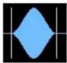
- To select a frequency band, tap and drag the selector left or right. To adjust gain of the selected filter, tap the red rotating X and slide up to boost or down to cut.

If Frequency Lock is off (blue), the frequency can also be selected and changed by directly tapping and dragging a yellow X filter point on the EQ interface.

Figure 4-35: Graphic EQ Screen
- Tap Filter Flat on the button bar to flatten the selected filter.
Many other features are available on the EQ button bar; please refer to chapter 6 for further details.
4.4.3 Ideal Graphic EQ TM
A unique innovation found in all Lake devices is the Ideal Graphic EQ. Conventional analog and digital Graphic equalizers do not provide intuitive results. For example, pulling up the faders on a conventional Graphic equalizer to boost 6 dB at 500; 630; 800; 1,000; 1,250; 1,600; and 2,000 Hz produces the frequency response shown in Figure 4-36.

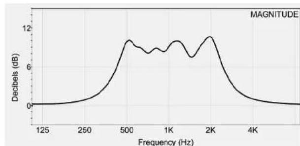
Figure 4-36: Conventional Graphic Equalization and Resulting Frequency Response
This measured frequency response is not what you would expect from the Graphic EQ controls.
If we use the Lake Controller GEQ overlay to boost 6 dB at 500; 630; 800; 1,000; 1,250; 1,600; and 2,000 Hz, the frequency response is shown by the flat top trace in Figure 4-37.


Figure 4-37: Lake Ideal Graphic EQ and Resulting Frequency Response
To implement this EQ overlay:
- Tap and drag the filter tool on the bottom to 500 Hz.
- Tap and drag the red X upward until the filter's gain parameter reads 6 dB.
- Perform these steps for each of the frequencies listed.
The bottom trace in Figure 4-37 shows that the adjacent filters on a Contour or Mesa EQ sum to flat, unlike all previous Graphic equalizer implementations. This is because of the raised cosine filters that give rise to the Ideal Graphic EQ.
Figure 3-7 shows a traditional third-octave Graphic EQ filter (red curve) in comparison to a third-octave raised cosine filter. The area highlighted gray shows the difference between the two filter shapes.

Figure 4-38: Comparison of Raised Cosine (blue) and Traditional Third-Octave (red)
4.4.4 EQ Overlays
The concept of EQ overlays is another innovative Lake feature. Tap the PEQ1 tab at the top of the screen. PEQ1, BLEQ2 and GEQ3 are all different EQ overlays. The white line represents the composite response of all EQ overlays, including those from the Module and Overlays from all assigned Groups. A grey line, if visible separate from the white line, indicates the EQ response for the selected overlay only.
With the PEQ1 screen selected in Figure 4-1 on page 27, the white line (composite curve) indicates the wide band 6 dB boost created in the GEQ3 overlay. The next section illustrates how multiple EQ overlays interact.
4.4.5 Parametric EQ
To add a Parametric filter to the PEQ1 overlay:
- Tap the Parametric filter at the top of the EQ display.
- Tap the screen near 125 Hz to insert the filter there.
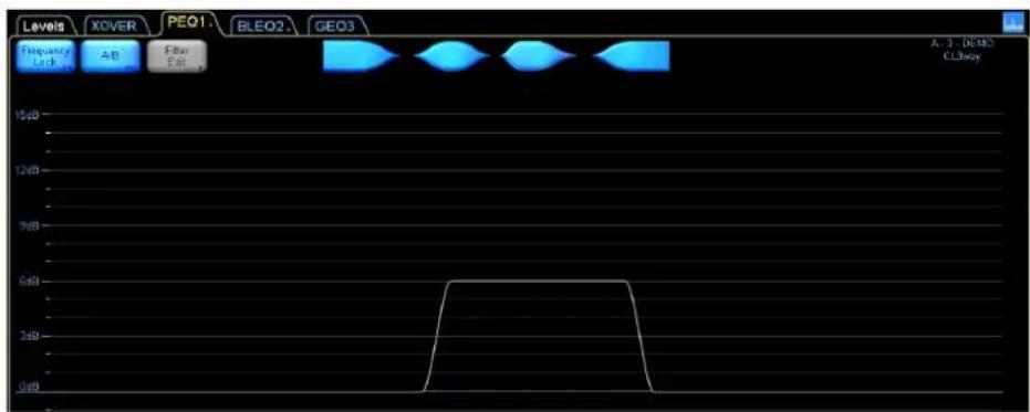
Figure 4-39: Adding a Parametric EQ filter on the PEQ1 Overlay
The Parametric filter tool is similar to the Graphic EQ tool except that the filter bandwidth is adjustable.
- Tap and drag the red X up to boost the volume of this frequency.
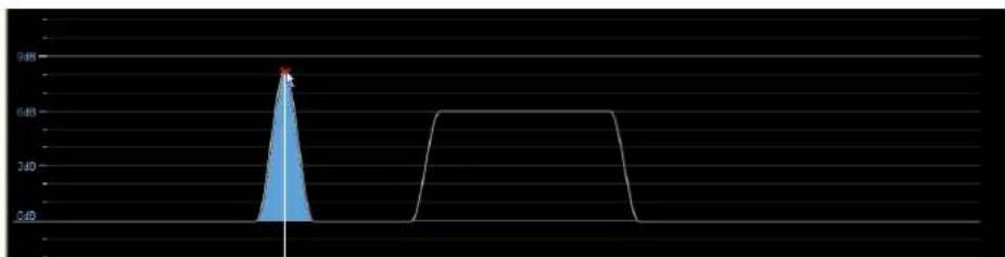
Figure 4-40: Changing filter gain by dragging the filter point
- Tap and drag either of the vertical end lines on the filter tool to increase the bandwidth as shown:

Figure 4-41: Changing the filter bandwidth using the EQ tool
- Change the center frequency of the Parametric filter by tapping and dragging inside the vertical divider lines of the EQ tool.

- Drag the Parametric filter into the same frequency range as the GEQ3 filters to see the result of all the filters (the white composite line in the previous figure).
4.4.6 Mesa Filter
The Mesa filter is a highly versatile filter that can rapidly adjust a loudspeaker's frequency response. The Mesa filter provides a fast, effective optimization tool that truly matches a loudspeaker's asymmetric response. The Mesa filter allows independent adjustment of the slopes and center frequencies of the lower and higher edges.
To add a Mesa filter to the PEQ1 overlay:
- Tap the Mesa filter type at the top of the EQ interface.
- Tap the EQ display near the frequency you wish to insert the Mesa filter.

Figure 4-42: Adding a Mesa filter
- Tap and drag up between the red X marks in the EQ display to increase gain.

Figure 4-43: Increasing the gain on a Mesa filter
The Mesa filter tool has four dividing lines.

Figure 4-44: Mesa EQ Filter Tool
- Tap between the center and right dividing lines and drag to the right. This spreads the filter points, creating a variable-width flat top.

Figure 4-45: Adjusting the Mesa filter width
- Tap and drag to the left of the far-left divider line.
Figure 4-46: Adjusting a Mesa Filter Slope

Figure 4-47: Effect of Adjusting the Mesa Filter Slope
The same principle applies to the high-frequency edge (right side).
- Tap and drag between the two center divider lines to change the frequency.
4.5 Crossovers
The Lake Controller, when used in conjunction with Contour loudspeaker Modules, allows real-time adjustments to crossovers through the XOVER screen.
Crossover frequency and type and post-crossover equalization can be adjusted. In the default three-way configuration, the Contour Module has 24 dB Linkwitz-Riley crossovers with center frequencies set at 250 Hz and 1.6 kHz. Tap the XOVER tab to view the crossover interface.

Figure 4-48: Crossover Screen
The low-output crossover is selected in this example. Use the crossover tool to change the center frequency. The low and high parts of the crossover are currently combined. Tap the CROSSOVER SPLIT button
to split the crossover, and drag the CROSSOVER SELECTOR tool left to reduce the frequencies sent to the low output.

Figure 4-49: Splitting and moving the low channel HPF
Parametric filters (with the exception of the Mesa filter) can be added to further modify the crossover. Add a Parametric filter near the center frequency of the low-output crossover.

Figure 4-50: Adding a Parametric EQ to the low channel
The full response of the Parametric filter is shown in blue, but the Parametric filter affects only the output it is associated with. The solid white line shows the resulting crossover curve for the low output.
Tap the CROSSOVER SELECT button to display the crossover scroll bar, from which you can select various standard crossover types. If crossover sections are combined, the new CROSSOVER SELECTION is applied to both sides of the selected crossover. If crossovers are split, the CROSSOVER SELECTION applies only to the currently selected output.
To change the crossover type to a 48 dB Linkwitz-Riley:
- Tap the 1.6 kHz filter box to select that crossover.
- Tap CROSSOVER SELECT.
- Select 48 dB Linkwitz/Riley from the scroll bar.
- Tap CROSSOVER SET.
- Tap YES in the dialog box to load the new crossover.
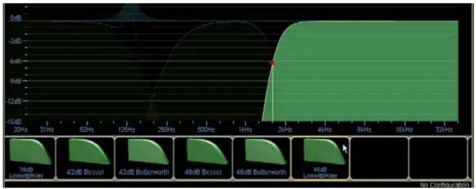
Figure 4-51: Changing the crossover slope
The crossover interface provides a fast and easy method for configuring your loudspeaker system. You can create your own presets or build them based upon data available from speaker manufacturers.
For XP modules 2-way, 3-way and 4-way, the XOVER screen has an Output selector available in the top right corner where the specific output is selected.

4.6 Groups
The Lake Controller allows Grouping of multiple Modules. This unique concept allows the EQ and levels of multiple Modules to be changed with a single adjustment. Every Module may be a member of up to 28 Groups.
All EQ functions available for a Module are also available for a Group, with a maximum of four EQ overlays per Group.
Most Levels functions are also available for Groups, except the following:
▶ LimiterMax RMS Corner ▶ LimiterMax RMS Attack ▶ LimiterMax RMS Release ▶ Input Headroom
▶ Control of output levels where the Group contains Modules of varying crossover types (e.g. 3-Way and 4-Way Modules assigned to the same Group).
4.6.6.1 Assigning Modules to a Group
To assign both Modules of a Frame to a Group:
- Tap the HOME button to locate to the MAIN page.
- Tap the GROUPS button to display the Groups scroll bar.
- Tap GROUP 1, and then tap the MAIN page to add the Group to your configuration.
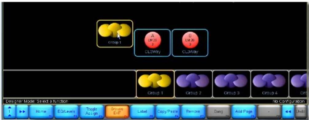
Figure 4-52: Adding a Group to the Main page
- Tap the TOGGLE ASSIGN button, and tap the icons for Modules A and B to assign them to the Group. Assigned Modules are highlighted with a yellow border. It is also possible to use multi-selection to assign, see section 10.3 Assign for further info.

Figure 4-53: Assigning Modules to a Group
- Tap the ASSIGN button again to exit ASSIGN mode.
- Tap GROUPS EXIT or HOME to return to the MAIN page.
4.7 Lake Controller File Types
Before saving the simple configuration just created, it is useful to learn about the file types used to store and recall settings within the Lake Controller software. The following sections describe the various file types.
4.7.1 Base Configuration Files
A base configuration file defines a starting point for the Module setup. It can contain EQ, crossover, and level settings that can be hidden or protected from end-user adjustment. The result of all EQ, levels, and crossover settings for the Module, and any Group that it belongs to, can be combined and stored in the base configuration file.

Figure 4-54: Contour [.cbm] & Mesa [.mbm] Base Configuration Files
4.7.2 Single Module File
These files store all information contained in the base configuration file plus user settings for each Module including the mute states, levels (gain, delay, and limiters), and equalization (filters and EQ overlays).
Figure 4-55: Contour [.csm] and Mesa [.msm] Single Module Files
4.7.3 System Configuration File
This file stores/recalls all information contained within all Contour or Mesa single-Module files on a given network, and additionally includes generic Frame data and all Group assignments and settings.

Figure 4-56: Lake Controller System Configuration File [.csc]
4.7.4 Storing a System Configuration
To store a system configuration file:
- Tap HOME.
- Tap SYSTEM STORE/RECALL to display the scroll bar.
- Tap the STORE SYSTEM button to display the on-screen keyboard.
- Name the system configuration 'Example' and tap OK. The system configuration is stored and the file is displayed in the scroll bar.
- Tap the file labelled 'Example' to select it. This activates all recall and store options on the SYSTEM STORE/RECALL button bar.
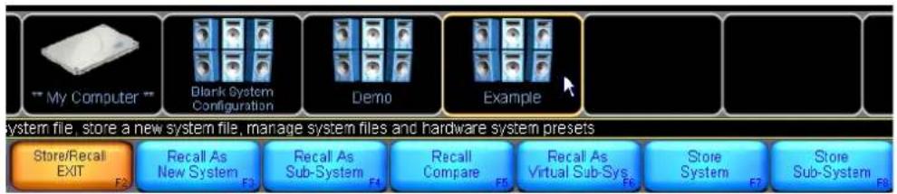
- RECALL AS NEW SYSTEM clears current configuration and loads the selected configuration.
- RECALL AS SUB-SYSTEM retains the current configuration and appends the selected configuration.
- RECALL COMPARE allows a comparison between the data stored on file and the current system configuration.
- RECALL AS VIRTUAL SS (Sub System) loads the data from the file into a virtual offline system, appending it to any currently recalled system configuration.
- STORE SYSTEM stores the entire configuration. STORE SUB-SYSTEM stores only the data in the selected Modules and Groups.
Individual Module settings can also be stored to a file. The single-Module file stores everything about a particular Module, including its EQ overlays, but does not retain Frame data (such as I/O config) or Group assignments. This file can be recalled into any Module of the same type (Contour/Mesa).
4.7.5 Storing a Single Module File
To store the settings of a single Module:
- Tap the HOME button, then tap MODULES.
- Select the Module 'My 3-Way'.
- Tap MODULE STORE/RECALL.
- Tap FILE UTILITIES, then NEW FOLDER.
- Enter the folder name 'Test', and tap OK.
- Tap FILE UTIL EXIT
- Double-tap the folder icon labelled 'Test' on the scroll bar to open it.
- Tap NEW STORE, name the file My 3-Way, then tap OK.
5. Home Menu Reference
This chapter provides detailed information on the top-level structure of the Lake Controller button bar, located at the bottom of every display within the software.
5.1 Main Screen Home Menu
When the Controller starts, the MAIN page, ALL page, and HOME button bar are displayed.
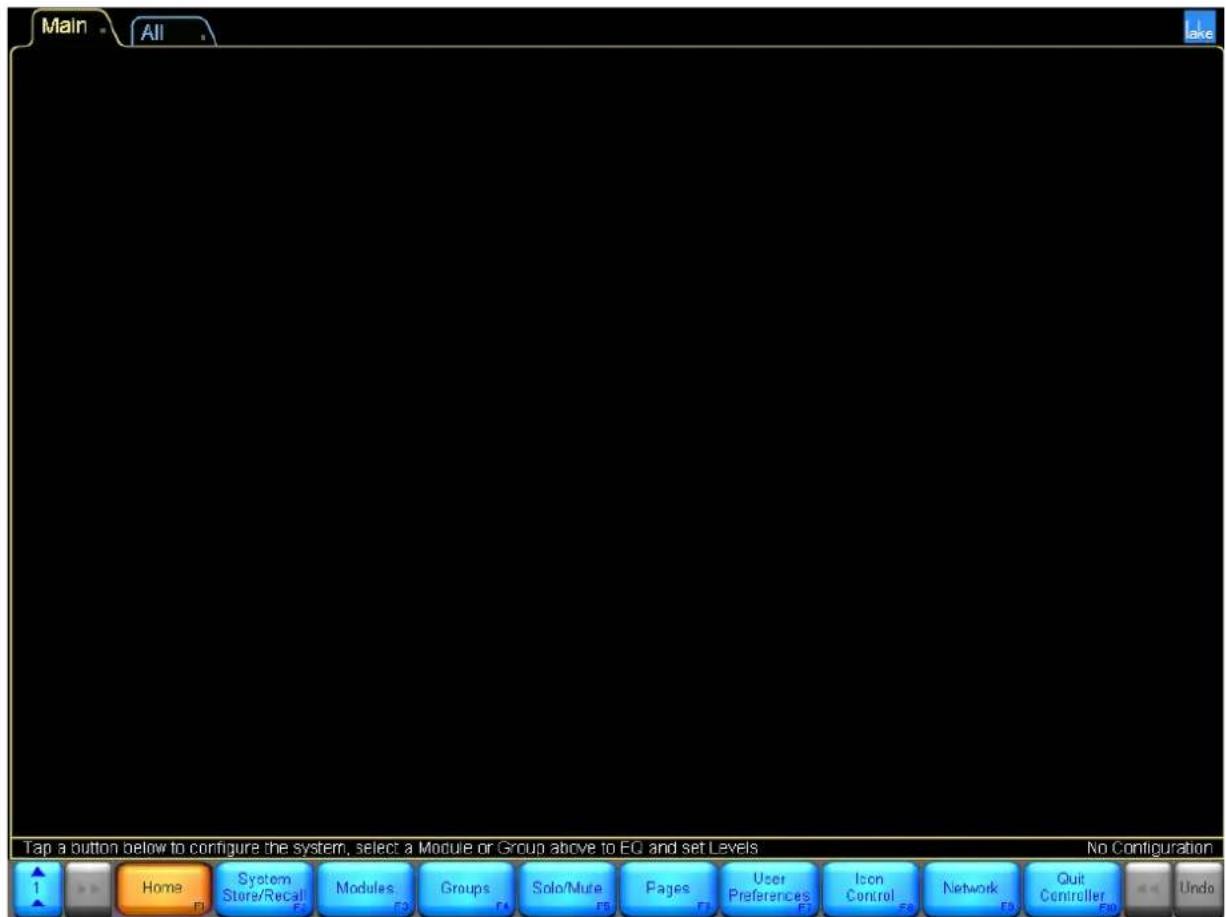
Figure 5-1: Main Screen - HOME Menu
From the HOME button bar, you can navigate to all user-interface displays and functions provided by the Controller. Table 5-1 provides a description of each button.
| Button Description | |
 | Available from most screens in the Lake Controller, the HOME button returns you to the top-level display. |
 | Submenu providing functionality for storing and recalling system configuration files. File utilities are also provided for creating, renaming, and deleting files and folders. |
 | Submenu providing Module functionality. This is one of the most extensive menus within the Controller, providing access to Modules, Super Modules, EQ, Levels, I/O Configuration, labeling, locking, copying, pasting, removing, recalling, and storing. |
 | Submenu providing Grouping functions. Groups are a powerful component of the Controller, allowing you to Group any number of Modules into logical partitions. Groups provide EQ level control across the set of Modules that are assigned to the given Group. |
 | Submenu providing solo and mute functionality. The solo/mute controls allow you to solo Modules and Groups, and also provide a mode to allow soloing for multiple Modules and Groups. |
 | Submenu providing page functions. You can add pages, label pages, and move Groups and Modules between the pages that you create. |
 | Submenu providing user preferences. These functions include contexts, delay units, designer mode functions, keyboard shortcuts, Graphic options (incl. windowed/fullscreen display modes), and show mode. |
 | Submenu providing options to control icon size and icon metering. |
 | Submenu providing network functions. You can select between available networks and access multiple-controller functions. |
 | Quits the Lake Controller. |
Table 5-1: Summary of HOME Menu Options
The menu reference chapters that follow this chapter provide detailed reference for each of the top-level functions on the HOME button bar.
5.2 Accessing EQ/Levels from HOME
When the Lake Controller displays the HOME button bar, you can tap any icon on the current page to immediately access the EQ/Levels interface for the given Module, Super Module, or Group. This provides instant access to the Module or Group, without having to navigate through the button bar to gain access to these most important parameters.
Tapping a Module icon from HOME is equivalent to the following sequence:
- From HOME, tap MODULES.
- Tap a Module icon to select the Module.
- Tap EQ/LEVELS.
Tapping a Group icon from HOME is equivalent to the following sequence:
- From HOME, tap GROUPS.
- Tap a Group icon to select the Group.
- Tap EQ/LEVELS.
Since the EQ/Levels interface for Modules and Groups is the most frequently used component of the Lake Controller, this is the first menu reference chapter to be presented.
6. EQ/Levels Menu Reference
The EQ/Levels functionality of the Lake Controller provides a sophisticated and accurate real-time interface to both Modules and Groups on the network. Modules and Groups require different features and functions for setup and configuration, although they provide the same EQ and level functionality for system optimization and during the show.
6.1 EQ/Levels Overview
Figure 6-1 shows a general overview of how Modules and Groups utilize the same EQ/Levels interface for access to the underlying signal processing parameters.![graph TD A["Modules"] --> C["EQ/Levels"] B["Groups"] --> C["EQ/Levels"] C --> D["Gain"] C --> E["Polarity"] C --> F["Delay"] C --> G["Limiters"] C --> H["EQ"] C --> I["XOVER"] C --> J["AUX"]](/content/2026/07/1419186/images/feb604f223dc98fc740ab616291d2eab9e297c86948e75d3ec4aad61a8d7804b.jpg)
Figure 6-1: EQ/Levels Overview
Modules, Super Modules, and Groups use the EQ/Levels interface to present gain, polarity, delay, limiter, EQ, crossover, and auxiliary output parameters to the sound engineer. When adjusting any of these parameters from a Module, the sound engineer makes changes to a single Module on the network. When adjusting any of these parameters from a Group, the sound engineer makes changes simultaneously to a Group of Modules on the network.
This chapter provides a menu reference for EQ/Levels functionality, which can be accessed from multiple locations within the Controller.
6.1.1 General Access
The EQ/LEVELS button accesses the following information:
Module and Group Parametric EQ (PEQ), Module and Group Band Level EQ (BLEQ), Module and Group Graphic EQ (GEQ) - Module and Group levels (gain, delays, limiters, etc.)
Module crossovers and high-pass filter/low-pass filter (HPF/LPF) (Contour) or HPF/LPF only (Mesa EQ)
The EQ/Levels functions can be accessed by several methods from the following menu locations:
HOME: Tap a Module/Group icon once. MODULES: Select a Module/Group icon, then tap the EQ/Levels button. GROUPS: Select a Module/Group icon, then tap the EQ/Levels button. SOLO/MUTE: Select a Module/Group icon, then tap the EQ/Levels button. I/O CONFIG: Tap a section of the interactive block diagram.
6.1.2 Restricted Access
The Lake Controller provides security by allowing a system designer to hide parts of the system or set them to View Only. This can be done globally in a system, or for individual Modules. This security specification may affect the screens allowed to be displayed when accessing EQ/Levels. Please refer to chapter 19 for further details.
6.1.3 Group Adjustments
Group EQ and levels are in "view only" mode when viewing via a Module. To adjust Group EQ or levels, access the Group EQ/Levels page via the Group icon.

Groups do not have a Xover or HPF/LPF page. However, the Gang Xover/Aux/HPF/LPF functions, available from the Groups menu, can be used to link the Xover/Aux/HPF/LPF for all Modules in a Group.

Group Gang is not available for XP Modules.
6.1.4 Default Settings
The following example shows the available screens and default EQ overlays for a Contour loudspeaker Module placed on the Main page of the Lake Controller.
![graph LR A["Levels"] --> B["XOVER"] B --> C["PEQ1"] C --> D["BLEQ2"] E["Frequency Lock"] --> F["A/B"] F --> G["Blue Bulb"] G --> H["Blue Bulb"] H --> I["Blue Bulb"]](/content/2026/07/1419186/images/c1e05c9f14b726e16280061dcc0132e665577c255a17dfe20361c0070a5cae06.jpg)
Figure 6-2: Default Screen Tabs for Contour Loudspeaker Module
The default Module contains a Classic 3-Way (CL3way) crossover. The default tabs for this Module are:
LEVELS: Displays gain, delay and limiters. XOVER: Displays crossover and output EQ settings. PEQ1: Parametric EQ overlay. BLEQ2: Band Level EQ overlay.
Tap the LEVELS tab to toggle between LEVELS and the XOVER / EQ screens.

These four screen tabs cannot be deleted, but they can be hidden if required. Please refer to the Designer Mode chapter in this manual for further details.
6.2 Levels
Figure 6-3 shows the LEVELS interface for a Classic 3-Way Module with letters identifying key features.![EQ ---- CL3Way Group 1 MODULE +4dBuRet [0.00] 0.00 dB MaxRMS Ret [0.00] 0.00 dB MaxRMS Ret [0.00] 0.00 dB MaxRMS Ret [0.00] 0.00 dB MaxRMS Ret [0.00] 0.00 dB MaxRMS Ret [0.00] 0.00 dB MaxRMS Ret [0.00] 0.00 dB MaxWRS Ret [0.00] 0.00 dB MaxWRS Ret [0.00] 0.00 dB MaxWRS Ret [0.00] 0.00 dB MaxWRS Ret […](/content/2026/07/1419186/images/70f3a9e5b5be5d3e0718087aeccfb950e35e554f80bb15e3358393e970d29ea2.jpg)
Figure 6-3: Levels Screen Overview Table 6-1 on page 69 provides definitions for the labels in Figure 6-3 above.
Level Limits
All levels are subject to limits set by the system designer. If you are unable to change a value to the desired level, this may be due to restrictions set for that channel.
Hidden Output Channels
A system designer may choose to hide an output channel if it is not being used. It is possible that the number of visible output channels will differ from the number suggested by the Module type.
| Label | Function Description | |
| A Parameter Values | For Modules, the value presented in brackets represents the overall parameter value, which includes any Groups the Module is assigned to. The bottom value (in the blue box) represents the value of the Module parameter.The Group parameter value is shown in the blue edit box. | |
| B Limiter Indicator | Indicates the total RMS and peak limiting gain reduction with an orange bar that moves downward as gain reduction increases. | |
| C Frame/Module/Group Label | Modules display the selected Module's name.Groups display the name of the Module providing metering. | |
| D Fader | Drag the fader up or down to adjust its level. Drag below, above, or to the left of the fader to adjust by smaller increments. | |
| E Additional Outputs | For a 4-, 5-, or 6-Way/Aux Module, additional output channels appear here. The number of output channels depends on the Module type. | |
| F Peak Level / Peak Hold | Indicates peak level with a thin green bar, and peak hold with a wide orange segment. | |
| G RMS Level Indicator Indicates RMS | level with a wide green bar. | |
| H | Input Channel Label Mute Button Polarity Button | The channel label is user defined. The color and label of the mute button identifies the mute status of the channel:A blue UNMUTED button = channel unmutedA red MUTED button = channel mutedModules: A red button with blue text denotes the channel has been muted by a Group the Module is assigned to. The polarity button for the channel is located to the right of the mute button.Groups: An orange button with blue text denotes that at least one Module in that Group has the channel muted. A red mute button with blue text denotes the channel is muted on all Modules in the Group. The polarity button is not available at Group level. |
| I Input Mixer | Modules only - provides access to the Input Mixer, which allows audio input channel from available Input Routers to be enabled, disabled, and mixed as required. | |
| J Input Router Mutes | Modules only - provides access to the Input Router Mutes, which will affect any Module on a device using selected Input Router. | |
| K Events & Control | Opens a screen containing product specific event logging and other features (not applicable for MY8-LAKE) | |
| L Levels Menu Button Bar | The functions and submenus available on the Levels screens are described throughout in this section. | |
Table 6-1: Function Descriptions for Levels Screen
6.21 Gain
Tap GAIN to display the gain levels for each channel of the selected Module/Group. To adjust gain values, drag the fader (D) for large increments, drag above or below the fader for fine adjustment, or tap the value (A) for keyboard entry.
6.2.2 Delay
Tap DELAY to display the delay time for each channel of the selected Module/Group. Delay values can be adjusted in four ways:
▶ Drag the fader (D) to adjust by large increments - Drag above or below the fader for fine adjustment - Drag on the meter to the left of the fader for very fine adjustment ▶ Tap the delay value (A) for keyboard entry
A total delay of 2,000 ms (input plus output) can be set, subject to level limits set by the system designer.
6.2.3 LimiterMax TM
Tap the LIMITERMAX button to view a submenu containing functions relating to the MaxRMS and MaxPeak limiters and access to the Multiband Limiter Configuration (XP modules only).
6.2.3.1 MaxRMS Level
Tap MAXRMS LEVEL to display the maximum RMS signal level (dB) allowed at the output. An orange bar moves downward from the top of the channel meter to indicate the limiting amount. To adjust Limiter MaxRMS values, drag the fader (D) for large increments, drag above or below the fader for fine adjustment, or tap the value (A) for keyboard entry.
The MaxRMS Level value is relative to the factory MaxRMS value (dBu). While dragging the fader, the total value is displayed in the status bar as dBu-rms, dBV-rms and Vrms.
6.2.3.2 MaxRMS Corner
MaxRMS Corner applies to Modules only; this function is inactive if a Group is selected.
This limiter corner function softens MaxRMS limiting by creating a curve that gradually introduces limiting. This function is similar to an audio compressor's knee function. For example, if MaxRMS Level equals -6
dB and Limiter Corner equals -4 dB, limiting begins gradually when the Max RMS level reaches -10 dB and increases until maximum limiting occurs at -6 dB.
Tap MAXRMS CORNER to display the value (dB) for each channel of the selected Module. To adjust, drag the fader (D) or tap the value (A) for keyboard entry.
6.2.3.3 MaxRMS Attack and MaxRMS Release
MaxRMS Attack MaxRMS Release apply only to Modules; these functions are inactive if a Group is selected.
The attack and release times (also referred to as 'time constants') determine the time in milliseconds that the MaxRMS Limiter takes to fully engage and disengage once the MaxRMS Corner level has been reached.
Tap MAXRMS ATTACK or MAXRMS RELEASE to display the value (ms) for each channel of the selected Module. To adjust the value, drag the fader (D) or tap the value (A) for keyboard entry.
6.2.3.4 Auto Time Constant
The MaxRMS attack and release values may be set manually by the user, or may be calculated automatically. Automatic calculation is determined by the crossover frequency of the channel's high-pass filter, if applicable. Otherwise, it is fixed at 160 ms.
The TC AUTO button is displayed underneath the slider when viewing either the attack or release settings. When TC AUTO is enabled (Orange), the slider is disabled and the attack or release values are calculated automatically.

Figure 6-4: Tc Auto Attack and Release Controls
6.2.3.5 MaxPeak Level
Tap MAXPEAK LEVEL to display the maximum peak signal level (dB) allowed at the output.
The MaxPeak limiter process is disabled when the total MaxPeak level (including Group and factory settings) is 25 dBu or greater.
An orange bar moves downward from the top of the channel meter to indicate the limiting amount. To adjust Limiter MaxPeak values, drag the fader (D) for large increments, drag above or below the fader for fine adjustment, or tap the value (A) for keyboard entry.
The MaxPeak Level value is relative to the factory MaxPeak value (dBu-pk). While dragging the fader, the total value is displayed in the status bar as dBu-pk, dBV-pk, and Vpk
6.2.3.6 Multiband Limiter (XP modules only)
For XP modules, there is an optional Multiband Limiter. Access to the Multiband Limiter is available via the Multiband Limiter button in the LimiterMax view. Note that for locked modules, the Multiband Limiter can be locked away by the creator of the Speaker Preset, or the Multiband Limiter button can be configured to go directly to All-view without any configuration accessible.
Figure 6-5: Multiband Limiter Configuration button
6.2.3.6.1 Multiband Limiter Configuration
The Multiband Limiter offers the ability to configure the limiter to act differently on different frequency bands within one module output. The advantage this offers over a full-bandwidth limiter is that audible “pumping” in other frequency bands is not caused by changing signal levels in a single frequency band. The Multiband Limiter offers up to three separate bands per Module Output. These bands can be merged if fewer bands are desired.
The crossover to divide the signal into the different bands uses proprietary Zero Phase Shift filters, which makes it possible to sum the bands. The Multiband Limiter can also be enabled on some of the outputs and disabled on others with minimal acoustic summing phase distortion. It is also possible to link the limiters between the bands in Soft, Medium or Hard options.
![Multiband Limiter Configuration - Demo - XP4way Module Output Low - 1 Band 1 Band 2 Band 3 Lmid - 2 Band 1 Band 2 Band 3 Hmid - 3 Band 1 Band 2 Band 3 High - 4 Band 1 Band 2 Band 3 ALL A B Split Frequency 60.0 Hz MaxRMS Ref [20.00] 20.00 dB Split Frequency 125.0 Hz MaxRMS Ref [20.00] 20.00 dB MaxRMS…](/content/2026/07/1419186/images/9024256285ef46179312c5799ef500188f938ad4dddc4a80b7c0504166f5a7d0.jpg)
Figure 6-6: Multiband Limiter Configuration view for an XP4way module with a three band MBL enabled on each of the four outputs
| Label Function Description | ||
| A Module Output Selector | Select the Module Output to work on. For an XP1way, there is only one module output. XP2way will display two outputs, XP3 will display three outputs and XP4 will display four outputs.Below the selector, the Label(s) of each band within that output are displayed.If the band is muted, the label is displayed in red. If the band is bypassed, the label is displayed in grey. The number of bands displayed depends on how many bands the output has. If the Multiband Limiter is disabled for an Output, it will say “DISABLED” in black on grey background. | |
| B Split | Frequency Control | Displays and enables adjustment of the split frequency used for the proprietary Zero Phase Shift crossover filters creating the bands. |
| C Enable the Multi-band Limiter | This button enables or disables the Multiband Limiter for the selected Module Output. This makes it possible to enable the Multiband Limiter on one or more of the Module outputs for the Module individually. | |
| D Select Fader Function | Selects what function the Fader will have:MaxRMS LevelMaxRMS CornerMaxRMS AttackMaxRMS ReleaseMaxPeal Level | |
| E Designer Mode Selections | These buttons are only available while in Designer mode for an unlocked module.Level Limits = will display the Level Limits configuration for the Multiband Limiter as well as other access rights.Adjust Factory = makes it possible to configure Factory offset values. | |
| F ALL The ALL view will display Meters and Mute buttons for all bands within the Module. For example, for a XP4way with all three bands enabled on each module output, ALL view will display all 12 bands at the same time. | ||
| G Band Button Each band | within the Multiband Limiter have a button below the meter. By default, this is a mute button, but the function for the button is selected in the Button Mode menu (I). The button can function for:Mute = Mute or unmute the selected bandBypass = Bypass all limiters for the bandLabel = Label the bandMerge/Split = Merge the center band with either the lower and/or the higher band, making it possible to create a two-band or one-band multiband limiter. | |
| H Module Output Button | Button for the Module Output selected in (A) and function selected in (I). | |
| I Select Button Function | This selection will decide the function of the band buttons (G) and Module output button (H) | |
| J | Band Fader | The band fader will adjust the limiter threshold for the function selected in (D).Drag the fader up or down to adjust its level. Drag below, above, or to the left of the fader to adjust by smaller increments. |
| K Band | Meter The band meter | meter will display RMS level with a wide green bar, display peak level with a thin green bar, and peak hold with a wide orange segment.The total RMS and peak limiting gain reduction is indicated with an orange bar that moves downward as gain reduction increases.When the Limiter is bypassed, the gain reduction meter changes to striped grey, indicating the amount of gain reduction that would have been applied to the signal if the limiter was inserted. |
| L Module Output Meter | The band meter will display RMS level with a wide green bar, peak level with a thin green bar, and peak hold with a wide orange segment.The total RMS and peak limiting gain reduction is indicated with an orange bar that moves downward as gain reduction increases. | |
Table 6-2: Function Description for Multiband Configuration Screen
6.2.4 Enable Mute
This button locks and unlocks the mute buttons and is active by default (that is, muting or unmuting is allowed). When the button is active (orange), channel muting via the Controller is enabled. When the button is inactive (blue), channel muting is disabled.
6.2.5 Enable Polarity
This button locks or unlocks the polarity buttons and is inactive by default (polarity buttons locked). When the button is active (orange), the polarity can be changed. When the button is inactive (blue), the polarity cannot be changed.

If a system designer has locked polarity changes on one or more outputs, the polarity button for the outputs will not be displayed in User mode.
6.2.6 Label Channel
This function applies to Modules only and is inactive if a Group is selected. Channel labels for Groups are derived from the Module that has been assigned for metering purposes as just described.
The channel label is a user-defined value that appears on the mute button at the bottom of each channel, the Module I/O CONFIG page, and on any auxiliary output EQ tabs.
To label a channel:
- Access a Module levels page through a Module icon.
- Tap LABEL CHANNEL, then tap the required channel label/mute button.
- Enter the channel label using the on-screen keyboard (or an external keyboard).
- Tap LABEL CHANNEL to exit this mode.
6.2.7 Meter Options
Tap the METER OPTIONS button to view a submenu containing functions relating to alternate meter views and system designer features.
6.2.7.1 Input +4dBu Reference
Tap INPUT +4dBu REFERENCE to view the physical input signal meter relative to +4 dBu. Tap the button again to return to the default Digital Clip [DClip] view.
The DClip metering mode shows the audio level prior to any gain adjustment (input headroom, or digital gain offset), and indicates when the A/D converters will clip. The +4 dBu metering mode shows the audio level after any gain adjustment, and is useful for comparing levels of different input signals prior to processing.
This is a global function; all physical input meters throughout the system display the reference selected here.
6.2.7.2 Pre Limiter
Tap the PRE LIMITER button to view the pre-limiter output signals. Tap again to return to post-limiter mode. This is a global function; all meters throughout the system display the reference selected here.

The limiter status is identified on the bottom right of each output meter above the channel label/mute button.
6.2.7.3 AmpClip Reference
Tap the AMPCLIP REFERENCE button to view output signals with respect to the AmpClip reference level. Tap again to return to the normal view, which is relative to the factory MaxRMS level as defined using Designer Mode.
When AMPCLIP REFERENCE is selected, the Amp Clip level is used as the reference for the 0 dB level on the meter. With correct settings, the output meter will identify the onset of clipping.
AMPCLIP REFERENCE is a global function; all meters throughout the system display the reference selected here.

The Multiband Limiter band meters are always MaxRMS.
6.27.4 Assign Meters
The ASSIGN METERS function is active only when a Group levels page is accessed via a Group icon. For metering purposes, a Module may be assigned to a Group. This provides an overview of the input/output signals for that Group.
When a Group is created, the first Module to be assigned to that Group is assigned to metering automatically.
To assign a Module to a Group for metering purposes:
- Access a Group LEVELS page through a Group icon.
- Tap METER OPTIONS, then tap ASSIGN METERS.
- The Module scroll bar appears displaying Modules assigned to the selected Group.
- On the scroll bar, tap the Module you wish to use for metering.
- Tap ASSIGN METERS again, then METER OPTIONS EXIT to exit this mode
6.2.7.5 AmpClip
AmpClip provides a parameter for scaling the output metering of the Lake device to calibrate the clipping point to a given amplifier's sensitivity. This value (the AmpClip reference level) is set in dBu and is a sum of the factory AmpClip value (dBu) and the user AmpClip value (dB).
In both AmpClip Reference and MaxRMS Reference metering modes, the output peak meters will turn red at the AmpClip reference level to indicate possible output clipping as shown in Figure 6-7.

Figure 6-7: AmpClip Level Indicators
6.27.6 Level Limits
This function button is visible only in Designer Mode, and is used for setting minimum and maximum values for all Levels attributes described in this chapter.
6.2.7.7 Adjust Factory
This function button is visible only in Designer Mode and is used for defining default level settings and level limits for all attributes described in this chapter.
6.3 Input EQ
The Controller has three types of input EQ: Parametric EQ, Band Level EQ and Graphic EQ. Additional Parametric output EQ is available on the XOVER page and Aux tabs. This section deals with input EQ.
Groups and Modules can have multiple layers of EQ, called EQ overlays. Each Module can have up to eight EQ overlays, and each Group can have up to four EQ overlays. A Module can have up to 256 input EQ filters distributed amongst these EQ overlays. The large number of filters is necessary in order to allow for sophisticated Grouping of Graphic EQ overlays. Input EQ Overlays can be stored and recalled from a file.
A Module's overall input EQ response is calculated by combining its input EQ overlays with those of all Groups to which that Module is assigned. The resulting composite EQ curve is indicated by a white line that is displayed on all overlays. A grey line, if visible separate from the white line, indicates the EQ response curve for the selected overlay only; refer to section 6.4.6.4 on page 100 for instruction on enabling/disabling this feature.
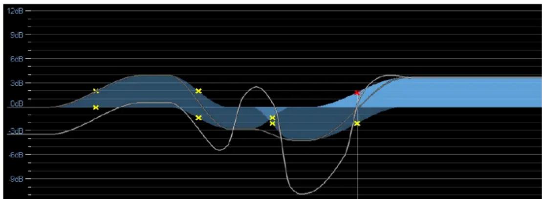
Figure 6-8: Composite EQ Curve (white line) + current Overlay response (grey line)
6.3.1 Default Overlays
Modules and Groups both use the same EQ overlays and EQ functions. If a Module is assigned to a Group, the Group EQ overlays can be viewed from the Module but cannot be updated. Changes to Group EQ are performed by accessing the Group's controls.
By default, a Module has Parametric EQ (PEQ1) and Band Level EQ (BLEQ2); a Group has a single Parametric EQ (PEQ1). A small gray dot to the bottom right of these EQ OVERLAY LABELs signifies they are default overlays that cannot be removed.
Figure 6-9: PEQ1 Tab
6.3.2 EQ Overlay Properties
A system designer can:
▶ Hide specific overlays ▶ Hide all overlays throughout the system ▶Set specific overlays to View Only ▶Set all overlays to View Only
It is important to note that a Module or Group may contain EQ overlays or filters that affect the overall EQ response, but are not visible or accessible to the end user (e.g. manufacture speaker presets)
6.3.3 Parametric EQ Screen
Figure 6-10 shows a Parametric EQ (PEQ1) screen, including letters marking its key functions.
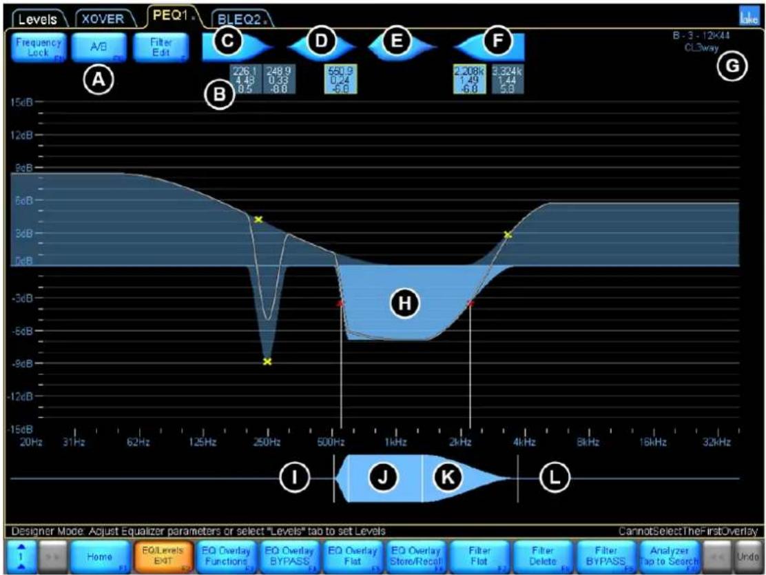
Figure 6-10: Parametric EQ Screen
Table 6-3 describes the functions labelled in Figure 6-10 above.
| Label | Function Description | |
| A | Frequency LockA/BFilter Edit | Refer to section 6.3.6 on page 85. |
| B | Filter Box | Displays the frequency, bandwidth, and gain values of each filter.Tap a filter box to select a particular filter.Double-tap the filter box to switch to Fine Adjustment mode.Drag the filter box down to bypass the filter.Drag the filter box up to insert.Drag the filter box off the top of the screen to delete. |
| C | Low Shelf Filter | Boost/cut low frequencies. The shelf filter can be adjusted from very shallow to extremely steep filter slopes. |
| D | Parametric Filter | Boost/cut a specified frequency band, from one-tenth of an octave to multiple octaves of bandwidth. |
| E | Mesa Filter | The unique Mesa filter contains two filter points that can be adjusted on either side to create a steep peak or a gentle slope with a variable-width flat-top frequency response. |
| F | High Shelf Filter | Boost/cut high frequencies. The shelf filter can be adjusted from very shallow to extremely steep filter slopes. |
| G | Module Icon Displays the currently selected Module and status information. | |
| H | Filter Shape EQ Curve | The selected filter is highlighted in light blue. The overall EQ curve is identified by a white line. |
| I | EQ Tool (Left Side) | Adjusts the filter bandwidth for Parametric, Mesa, and high-shelf filters by dragging left or right. |
| J | EQ Tool (Center) | Changes the frequency of the selected filter by dragging left or right. |
| K | EQ Tool (Flat Top) | Drag left or right at this point on either side of (J) to adjust the flat top width of the Mesa filter. |
| L | EQ Tool (Right Side) | Adjusts the filter octave width for Parametric, Mesa, and low-shelf filters by dragging left or right. |
| M | EQ Menu Button Bar | The functions and submenus available on the EQ overlays are described in the following sections. |
Table 6-3: Function Descriptions for Parametric EQ Screen
To add an EQ filter to a Parametric EQ overlay:
- Tap the required Parametric EQ shape (C, D, E, or F).
- Tap again anywhere on the EQ curve (H).
- Boost/cut the frequency gain by dragging the filter point up or down.

If a mouse with a wheel is attached to the computer, you can use the wheel to adjust the gain of the selected filter.
- Adjust the frequency by dragging the filter point left or right.
If FREQUENCY LOCK (A) is active (orange), you cannot adjust the frequency by dragging the filter point in the main EQ overlay display. Deactivate FREQUENCY LOCK (A) or use the EQ Tool (J) to adjust frequency.
6.3.4 Band Level EQ Screen
Figure 6-11 shows a Band Level EQ (BLEQ2) screen, including letters marking its key functions.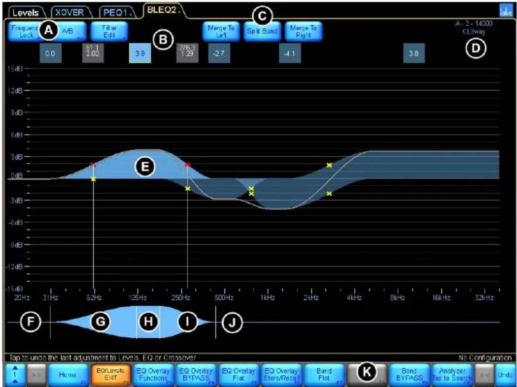
Figure 6-11: Band Level EQ Screen
On a BLEQ overlay the EQ filters are linked together, creating bands. Changing one band will also change the linked neighboring filter(s). By default, the BLEQ overlay has three bands. Any band can be split into two bands making it possible to create up to eight bands.
When fewer bands are required, bands can be merged together. Select a band and then tap MERGE TO RIGHT to merge the selected band with the band to the right; MERGE TO LEFT will merge the selected band with the band to the left. The MERGE TO LEFT and MERGE TO RIGHT functions replace the FILTER DELETE function for this overlay type.
| Label | Function Description | |
| A | Frequency LockA/BFilter Edit | Refer to section 6.3.6. |
| B | Filter Box | Displays the gain value of each band or the frequency & bandwidth of the currently selected band.Tap a filter box containing a single gain value to select a particular band.Double-tap the filter box to switch to Fine Adjustment mode.Drag the filter box down to bypass the band.Drag the filter box up to insert the band. |
| C | Merge to LeftSplit BandMerge to Right | Functions to combine or split the selected band |
| D | Frame and Module Label Displays the currently selected Frame and Module labels. | |
| E | Filter Shape EQ Curve | The selected band is highlighted in light blue. The overall EQ curve is identified by a white line. |
| F | EQ Tool (Left Side) | Adjusts the filter bandwidth for the low-freq filter for the selected band (and any adjoining filter) |
| G | EQ Tool (Left Outer) | Adjusts the centre frequency of the low-freq filter for the selected band (and any adjoining filter) |
| H | EQ Tool (Centre) | Adjust the centre frequency of both filters for the selected band (and any adjoining filters) |
| I | EQ Tool (Right Inner) | Adjusts the centre frequency of the hi-freq filter for the selected band (and any adjoining filters) |
| J | EQ Tool (Right Outer) | Adjusts the filter bandwidth for the hi-freq filter for the selected band (and any adjoining filter) |
| K | EQ Menu Button Bar | The functions and submenus available on the EQ overlays are described in the following sections. |
Table 6-4: Function Descriptions for Band Level EQ Screen
6.3.5 Graphic EQ Screen
The Lake Controller provides a 28-band Graphic EQ overlay. This overlay is not present by default and must first be created by following the steps below:
- From the PEQ1 or BLEQ2 screens, tap EQ OVERLAY FUNCTIONS
- Tap EQ OVERLAY NEW
- Tap GRAPHIC EQ
Figure 6-12 shows the Graphic EQ (GEO3) screen that will appear along with letters identifying key functions that are described in Table 6-5.
Figure 6-12: Graphic EQ Overlay
| Label | Function Description | |
| A | Frequency LockA/BFilter Edit | Refer to section 6.3.6 on page 85. |
| B | Filter Box | Displays the frequency, bandwidth, and gain values of each filter.Tap a filter box to select a particular filter.Double-tap the filter box to switch to Fine Adjustment mode.Drag the filter box down to bypass the filter.Drag the filter box up to insert.Drag the filter box off the top of the screen to delete. |
| C | Frame & Module Label Describes the currently selected Module and status. | |
| D | EQ Curve A white line identifies the overall EQ curve. | |
| E | EQ Tool Drag the EQ Tool left or right to select the frequency to change. |
Table 6-5: Function Descriptions for Graphic EQ Screen
To adjust the Graphic EQ:
- Select the filter point to adjust using the EQ Tool (E).
- Drag the filter point up or down to increase or decrease gain.
If FREQUENCY LOCK (A) is inactive (BLUE), you can tap to select a filter point then drag up or down to adjust the gain.
6.3.6 Input EQ On-Screen Functions
The following three functions are permanently available on all input EQ overlays in addition to those available on the button bar at the bottom of the screen.
6.3.6.1 Frequency Lock
Frequency Lock provides an option to lock the selected frequency to ensure when dragging the filter point up and down to change gain inadvertently change the frequency.
If FREQUENCY LOCK is blue then filter frequency is unlocked; the frequency is locked if the button is orange. When locked, the frequency can be adjusted using the EQ Tool (J) or FILTER EDIT functionality.
6.3.6.2 Overlay A/B
Tapping the A/B button creates a bypassed copy of the selected overlay. Changes can then be made to one version of the EQ overlay and the two overlays compared by tapping EQ OVERLAY COMPARE (F4), or by dragging one of the overlays up or down to switch between the two.
Tapping A/B Mode EXIT will exit this EQ comparison mode and delete the bypassed overlay.
6.3.6.3 Filter Edit
This function allows manual entry of gain (dB), frequency (Hz), and bandwidth (octave) for the selected filter. If a PEQ overlay is selected and the FILTER EDIT button is pressed, the Parametric shapes are replaced with the values of the selected filter

Figure 6-13: Manual Filter Edit Options
To adjust filter parameters using FILTER EDIT:
- Tap the overlay to select it.
- Tap the filter box, or use the EQ Tool to select the filter.
- Tap FILTER EDIT.
- Tap the gain, frequency, or bandwidth value (highlighted in blue).
- Enter the value required using the on-screen keyboard (or an external keyboard), and tap OK. The FILTER EDIT function is inactive if the selected overlay does not contain any filters.

High-frequency values can be entered using k to denote kHz, instead of Hz (for example, 12k instead of 12,000 Hz).
6.3.7 Input EQ Menu Reference
The button bar presented while viewing the Input EQ display provides a number of applicable functions for adjusting EQ and configuring EQ overlays.

Figure 6-14: EQ/Levels Menu
EQ OVERLAY FUNCTIONS, immediately to the right of the EQ/LEVELS button, provides a submenu with the following items:

Figure 6-15: EQ Overlay Functions Menu
6.3.7.1 EQ Overlay Properties/EQ Preferences
In User Mode, the only function active under the EQ OVERLAY PROPERTIES menu is EQ PREFERENCES, which provides a submenu containing functions that control the view of the EQ scale and screens.
Separate settings can be stored for crossover EQ and input/auxiliary EQ. Therefore, most changes made using EQ OVERLAY PROPERTIES/EQ PREFERENCES affect only the input and auxiliary output EQ scales.
| Function Description | |
| No Scale [F2] Removes the scale lines on all EQ/Crossover and Auxiliary screens. | |
| Reset Scale [F3] Resets the EQ scale to the default setting of ±15 dB. | |
| Zoom In [F4] | Zooms the EQ scale in by 3 dB increments (for example, if scale is ±15 dB, tapping Zoom In will change the scale to ±12 dB). |
| Zoom Out [F5] | Zooms the EQ scale out by 3 dB increments (for example, if scale is ±15 dB, tapping Zoom Out will change the scale to ±18 dB). |
| EQ Pref Exit [F6] Returns the previous menu level. | |
| Full Response [F7] | Available only for Crossover and Auxiliary Output screens. When active (orange), the overall EQ curve is shown taking into account all crossovers, HPF, LPF, input and output EQ (and any loaded FIR for the XP module) for the Module and any Groups it is assigned to. Not applicable for input EQ screens (PEQ/BLEQ/GEQ). |
| Up [F8] Moves the zero line up in 3 dB increments. | |
| Down [F9] Moves the zero line down in 3 dB increments. | |
| Current OVLAY Response | Available only for input EQ overlays (PEQ/BLEQ/GEQ). Enable (orange) by default. When enabled, a grey line is displayed for the selected EQ overlay to show EQ response for the current overlay only. The white line (overall EQ composite curve) remains present at all times. |
Table 6-6: Function Descriptions for EQ Preferences Menu
6.3.7.2 EQ Overlay Hide/EQ Overlay View Only
These functions are active only when in Designer Mode. Please refer to chapter 19.
6.3.7.3 EQ Overlay Type
The EQ Overlay Type menu provides options to convert any overlay to Parametric (PEQ), Band Level (BLEQ) or Graphic (GEQ) EQ overlays.
The current Overlay type is indicated by an orange button, and other available options are indicated by blue buttons.
While in Multiple Controller mode the EQ Overlay Type function is disabled for conversions to or from GEQ Overlays.

Changing the EQ overlay type will flatten and delete all existing filters from the selected EQ overlay.
6.3.7.4 EQ Overlay Delete
EQ OVERLAY DELETE is inactive for the default overlays. An overlay created by a user may be deleted by selecting the overlay and tapping EQ OVERLAY DELETE. If the overlay contains filters, a warning message will be displayed.
6.3.7.5 EQ Overlay Copy
Tap EQ OVERLAY COPY to copy the selected overlay. This function is used in conjunction with EQ OVERLAY PASTE OVER.
6.3.7.6 EQ Overlay New
Tap OVERLAY NEW then select an EQ Overlay Type to create an additional EQ overlay.
GEQ Overlays cannot be created while in multiple controller mode.

Each Module can have up to eight overlays; Groups can have up to four overlays.
6.3.7.7 EQ Overlay Paste Over
After using the EQ OVERLAY COPY action, tapping EQ OVERLAY PASTE OVER pastes the copied data into the selected overlay, overwriting its previous content.
6.3.7.8 EQ Overlay Label
An EQ Overlay Label is a user-defined value that appears on the overlay tab at the top of the screen.
To label an overlay:
- Tap the desired overlay tab.
- Tap EQ OVERLAY LABEL.
- Enter the label name using the on-screen keyboard (or an external keyboard).
- Tap OK.

The EQ Overlay Label is also stored as part of the EQ Overlay file although the filename for the EQ Overlay file can be set as required.
6.3.8 EQ Overlay Bypass/Insert/Compare
This button's label changes depending on whether the selected overlay is currently active or bypassed.
If the overlay is active, the button reads EQ OVERLAY BYPASS. Tap the button to bypass the overlay. A bypassed overlay is displayed at the bottom of the screen, just above the button bar.
If the overlay is bypassed, the button reads EQ OVERLAY INSERT. Tap the button to insert the overlay. An active overlay is displayed at the top of the screen.
If a bypassed overlay is placed directly underneath an active overlay, the button reads EQ OVERLAY COMPARE.

An overlay can be bypassed by dragging the overlay tab downwards or inserted by dragging upwards. In A/B mode, dragging up or down swaps the active/bypassed overlays.
6.3.8.1 A/B Overlay Compare
In addition to the bypass feature, you can compare two overlays within a Module or Group. The two ways to create an A/B comparison are described in the following sections.
6.3.8.2 Using the A/B Button
The A/B button at the top left of the screen creates a bypassed copy of the selected overlay. Changes can then be made to one of the overlays, and compared by tapping EQ OVERLAY COMPARE, or just pull down on the inserted overlay and it will switch with the other overlay.
6.3.8.3 Comparing Existing Overlays
Follow this process to compare two existing EQ overlays:
- Tap overlay A to select it.
- Tap EQ OVERLAY BYPASS. Overlay A moves to the bottom of the screen.
- Tap EQ OVERLAY COMPARE.
- Tap and drag overlay A left or right along the bottom of the screen until it is aligned directly underneath the EQ overlay you wish to compare.
Each time the button is tapped, the two overlays switch positions; the top overlay is active and the bottom is bypassed.
6.3.9 EQ Overlay Store/Recall
The EQ Overlay Store/Recall button opens a submenu containing functions relating to storing and recalling EQ overlays.
6.3.9.1 Recall As New
Selecting a previously stored EQ Overlay file and tapping RECALL AS NEW loads the selected EQ Overlay file as a new additional EQ Overlay. A module can have up to eight EQ Overlays, and a Group can have up to four EQ Overlays.
6.3.9.2 Recall
Selecting a previously stored EQ Overlay file and tapping RECALL (or double-tapping the icon) loads the EQ Overlay into the currently selected EQ Overlay, replacing all settings.
6.3.9.3 Store
Tapping STORE will store the currently selected EQ Overlay into the selected EQ Overlay file overwriting its content.
6.3.9.4 New Store
Tapping NEW STORE will store the currently selected EQ Overlay into a new EQ Overlay file, providing the ability to enter a filename via the on-screen or manual keyboard. Ensure the Overlay is appropriately labelled before storing; the EQ Overlay filename is independent from the OVERLAY LABEL.

EQ Overlays with Hidden or View Only properties cannot be stored to an EQ Overlay File.
6.3.9.5 File Utilities
This button provides a submenu containing further functions that manage files and folders from within the Lake Controller.
Open
This button is active only when a folder is selected. Tap OPEN to open the selected folder.
Read Only
This function protects important files from being accidentally overwritten or deleted and is active only when a file is selected. The currently selected file's status is identified by the color of the READ ONLY button:
▶ ORANGE - indicates the selected file is set to READ ONLY. BLUE - indicates the selected file is not protected.
To change the Read Only status of a file:
- Tap a file from the scroll bar to select it.
- Tap READ ONLY to toggle function ON (orange) and OFF (blue).
Rename
This button allows the name of a file/folder to be changed.
- Tap the required file/folder from the scroll bar, then tap RENAME.
- Enter the new name, and tap OK.
Delete
This button is active only when a file or folder is selected. When a file is selected, this function will only be available if the file is not set to READ ONLY. To delete a file or folder:
- Tap a file or folder to select it, then tap DELETE.
- Confirm action by tapping YES in the warning message.

Deletion of a file is permanent and cannot be restored using the UNDO function.
New Folder
This button creates a new folder in the current directory.
- Navigate to the desired directory location and tap NEW FOLDER.
- Enter the folder name, and tap OK.
6.3.10 EQ Overlay Flat
Tap EQ OVERLAY FLAT to flatten and delete all filters from the selected overlay. This function is inactive if the selected overlay does not contain any filters.
6.3.11 Filter Bypass/Filter Insert
The button label changes depending on whether the selected filter is active or bypassed. The button reads:
FILTER BYPASS: If the filter is active; tap to bypass the filter.
FILTER INSERT: If the filter is bypassed; tap to insert the filter.
The FILTER EDIT box of a bypassed filter is positioned slightly lower than an active filter's edit box and does not have a yellow border when selected.

A filter can be bypassed/inserted by dragging the filter edit box down (bypass) or up (insert).
6.3.12 Filter Flat
Tap FILTER FLAT to flatten the selected filter. This sets the filter gain to zero, but frequency and bandwidth remain unchanged.
FILTER FLAT is inactive if the selected overlay does not contain any filters.
6.3.13 Filter Delete
Tap FILTER DELETE to remove the selected filter from the overlay.

A PEO filter can be deleted by dragging the filter box upward off the screen.
FILTER DELETE is inactive if the selected overlay is a:
Graphic EQ, because its filter points are fixed and cannot be deleted - Parametric EQ overlay without any filters.
6.3.14 Analyzer Tap to Search
The Lake Controller can interface directly with certain audio analyzer software programs that are installed on the same computer, or on another computer on the same network.
When the analyzer is enabled, and a compatible audio analyzer is online and on the same network, the Lake Controller provides spectrum, spectrograph, and transfer function displays on the XOVER, Aux, and EQ overlays.
6.3.15 High-Precision Filter Adjustments
Double-tap the filter parameters box so it turns from its normal appearance to a gray outline and gray text. This switches from Normal Adjustment to Fine Adjustment mode. To return to Normal Adjustment mode, tap the filter box once. Fine Adjustment mode is also implemented globally when Show mode is selected.
6.4 Crossovers and HPF/LPF
The XOVER and HPF/LPF screens display the crossover and/or HPF/LPF information for the selected Module, depending on the Module type. The XOVER and HPF/LPF screens do not apply to Groups.
To view the XOVER screen:
- Access EQ/LEVELS, and tap the EQ page tab at the top left of the screen.
- Tap the XOVER or HPF/LPF tab next to Levels at the top of screen.
Figure 6-16 shows the XOVER screen along with letters marking key functions that are described in Table 6-7.
Figure 6-16: Xover Screen
| Label | Function Description | |
| A | Frequency LockHPF EnableFilter Edit | Frequency Lock is relevant only to Parametric filters (B, C, and D).When button is blue, the filter frequency is unlocked. When the button is orange, the filter frequency is locked (i.e. can only be adjusted with the EQ Tool).HPF Enable activates or deactivates the high-pass filter (HPF).When button is blue the HPF is disabled, when orange the HPF is enabled.filter edit enables filter edit data entry mode for the selected filter. |
| B | Low Shelf Filter(Xover/Aux) Used to | boost/cut low frequencies. |
| C | Parametric Filter (Xover/Aux) | Used to boost/cut a specific frequency band. |
| D | High Shelf Filter (Xover/Aux) Used to | boost/cut high frequencies. |
| E | Filter Edit Box | Displays the crossover or HPF/LPF center frequency and type, or the details of any EQ filters on the selected output. |
| F | Module/Frame Labels and Selected Output Channel Label | This area of the screen displays the Frame and Module labels and the selected output label. |
| G | Low Output Frequency Range (Selected) | The lowest frequency output of the crossover. This output channel is the currently selected crossover filter, identified by light green shading. A solid white line identifies the frequency response of this output channel. |
| H | Mid Output Frequency Range | The pass band crossover that is currently not selected, as identified by dark green shading. |
| I | High Output Frequency Range | The highest frequency output of the crossover.For a two-way Module, the Xover screen displays two crossover channels instead of three. |
| J | Crossover/Filter Point | An X marks the frequency at which the output filters cross over. Parametric filter points are also identified by a red (selected) or yellow (not selected). Only filter points/filter boxes for the selected output are displayed. |
| K | Crossover Selector | This is used to change the crossover frequency and to select the side of the crossover you wish to affect. Light green denotes the selected half, and dark green is not selected. When a PEQ filter is selected, the crossover selector changes to the blue EQ filter tool. |
| L | Crossover Menu Button Bar | The functions and submenus available on the Xover page are described in the following sections. |
Table 6-7: Function Descriptions for Xover Screen
6.4.1 Using the High-pass Filter (HPF Enable)
The high-pass filter filters all frequencies below the specified frequency. Input HPF and Low Output HPF are available. Input HPF affects all output channels; Low Output HPF affects only the lowest output of the Module. These two different modes of operation are provided in order to satisfy the requirements of various loudspeaker manufacturers' required signal-processing configurations.
To set the Low Output HPF:
- Tap HPF ENABLE, then tap HPF Select.
- Select a filter from the scroll bar (24 dB or less).
- Tap HPF Set, then YES to the warning message.
To change the HPF to affect all outputs (Input HPF):
- Tap CROSSOVER FUNCTIONS, then HPF Functions.
- Tap INPUT HPF.
While in this mode, move the HPF center frequency, and note how it affects all outputs of the Module.

The center frequency of the HPF can be set to a minimum of 10 Hz using the Filter Edit function.
6.4.2 Filter Edit
Tap FILTER EDIT to manually enter values for a selected filter using the on-screen (or external) keyboard. The values available for adjustment depend on whether a crossover or PEQ filter is selected. For a crossover, HPF or LPF only the frequency can be edited; for a Parametric EQ filter the gain (dB), frequency (Hz), and width (octave) can be edited.
To manually edit a filter:
- Tap the filter box, then tap FILTER EDIT.
- Tap the value to edit at the top of the screen (highlighted in blue).
- Enter the value using the on-screen (or external) keyboard, and tap OK.
- Tap FILTER EDIT again to exit this mode.
6.4.3 Using EQ Filters on the Xover Screen
The XOVER screen provides low-shelf (B), Parametric (C), and high-shelf (D) filters to shape the audio from each output as required. When used on the XOVER screen, the Parametric EQ filters affect only the selected output.

Only EQ filter points and filter boxes of the selected output are displayed. To select an output, tap the associated green filter box and toggle between outputs using the crossover tool.
Figure 6-17 shows a Parametric filter used to affect audio on output 1, the first channel of Module A. Letter-labeled references in this example are used in the subsequent instructions.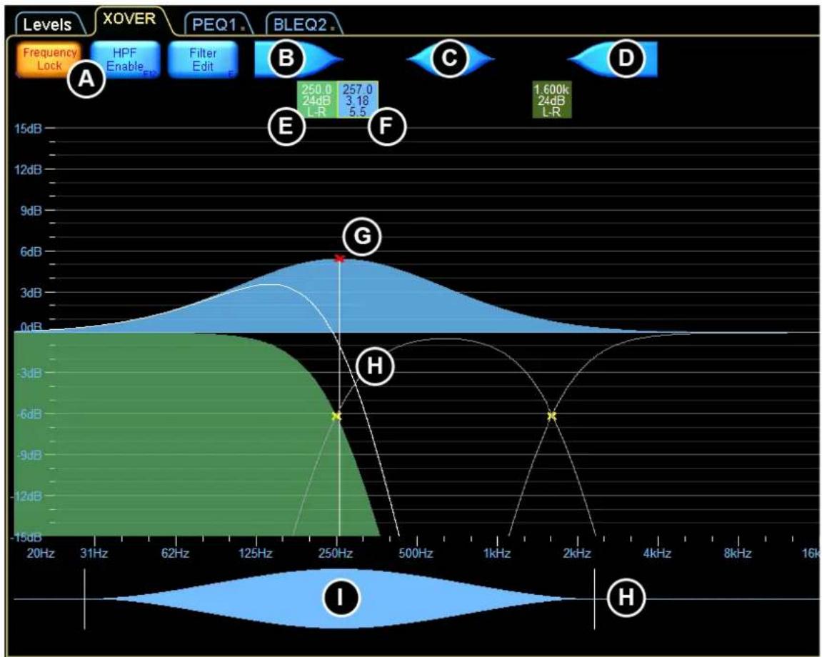
Figure 6-17: Using Output EQ Filters on the Xover Screen
Although this Parametric filter crosses the range used by all outputs, it affects only the range of the selected output. The curved white line identifies the effect the Parametric filter has on output 1.
To add Parametric EQ to an output:
- Tap the required crossover filter box (F) to select the crossover.
- Use the crossover tool to select the required output of the crossover (light green is selected).
- Tap an EQ filter (B, C, or D), and tap again in middle of screen.
- Boost/cut the frequency gain by dragging the filter point (G) up/down.
- Adjust the frequency by dragging the filter point (G) left or right. If FREQUENCY LOCK (A) is active (orange), you cannot change the frequency by dragging the filter point. Either deactivate FREQUENCY LOCK or use the EQ Tool (I) to change the frequency.
- Adjust the bandwidth by dragging to the left or right of the shape tool (J).
6.4.4 Linear Phase Crossovers
The linear phase crossover Modules provide steep crossovers without phase distortion. Figure 6-18 shows the XOVER screen for a Linear Phase Brick Wall 4-Way Module (LP4way).

Figure 6-18: Linear Phase Crossover Screen
While most of the button bar functions are the same, some XOVER menu options and functions are different for linear phase Modules. These differences are identified in the following sections.
6.4.5 XP Crossovers
The XP Module crossover provides LPF and HPF filters as well as 384 taps of FIR for each output.
The XP Module can be used with 1 to 4 outputs with XP1way, XP2way, XP3way or XP4way. Selections are made with the Output Selector in the top right corner.
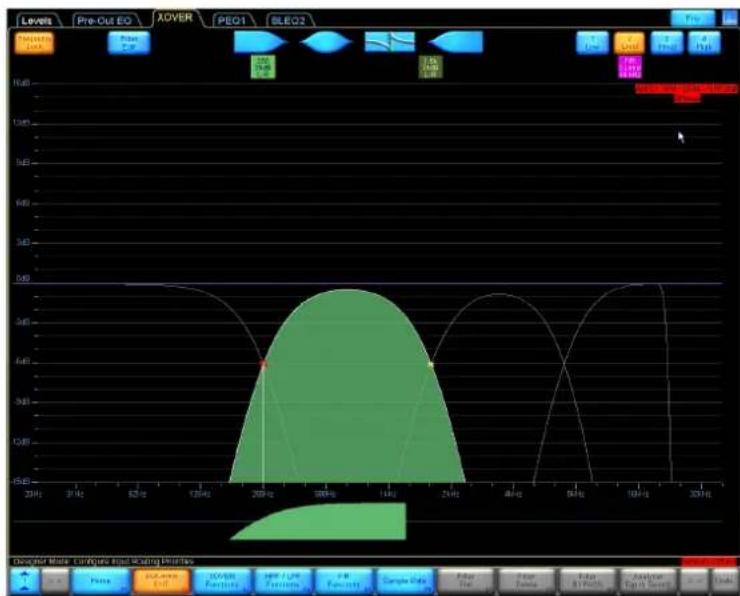
Figure 6-19: XP4way Module XOVER view with Output 2 selected
6.4.5.1 FIR import
Importing a FIR filter is done via the FIR Functions menu.
The file extension is .fir and the format requires one tap per row in the file.
The XP output channel can be configured to different sample rates (12, 24 or 48 kHz) and this will affect the FIR filter. The FIR filter response is displayed with a purple line in the XOVER view and the FIR filter is also included in the solid white line showing the resulting crossover curve.
6.4.6 Crossover Functions
CROSSOVER FUNCTIONS provides a submenu containing the following functions:
6.4.6.1 HPF/LPF Functions
HPF/LPF FUNC EXIT exits this menu and returns to the CROSSOVER FUNCTIONS menu. ▶ INPUT HPF SETs the HPF to affect all output channels for the Module (depending on the frequency of the HPF and outputs). Applicable to Contour Modules only. - LOW OUTPUT HPF SETs the HPF to affect only the lowest output channel of the selected Module. Applicable to Contour Modules only. HPF ENABLE enables/disables the HPF for the selected Module. LPF ENABLE enables/disables the LPF on the highest output channel for the selected Module.

INPUT HPF and LOW OUTPUT HPF are disabled for the Linear Phase Brick Wall 4-Way Module. The LP4way HPF is fixed to INPUT HPF. Other Module types, incl. LP2/LP3way provide the HPF option.
6.4.6.2 Crossover Hide
Available only in Designer Mode. When enabled (orange), the crossover page will be hidden when the Module is locked, or after exiting from Designer Mode.
6.4.6.3 Crossover View Only
Available only in Designer Mode. When enabled (orange), the crossover page will be set as view only when the Module is locked, or after exiting from Designer Mode.
6.4.6.4 EQ Preferences
This provides a submenu containing options regarding the view of the EQ scale.
6.4.6.5 Crossover Copy
Copies all crossover and EQ settings from the selected XOVER or HPF/LPF page.
6.4.6.6 Crossover Paste
Active only when a crossover or HPF/LPF page has previously been copied and the current Module is the same type.
A crossover can only be pasted to a Module of the same number of channels and the same type. For example, a Classic 3-Way crossover can only be pasted into another Classic 3-Way crossover; the HPF/LPF of a Mesa EQ Module can only be pasted onto another Mesa EQ HPF/LPF page; and a Classic 4-Way crossover cannot be pasted into a Linear Phase Brick Wall 4-Way.

CROSSOVER COPY and CROSSOVER PASTE only transfer the crossover and output EQ settings. Levels and input EQ (PEQ/BLEQ/GEO) will not be transferred to the destination Module.
6.4.7 Crossover Split/Crossover Combine/Alignment Delay
This button's label depends on the state of the currently selected crossover and the Module type. A classic crossover Module will read CROSSOVER SPLIT / CROSSOVER COMBINE; a linear phase Module will read ALIGNMENT DELAY.
6.4.7.1 Crossover Split
The label reads CROSSOVER SPLIT when a filter box is selected for a classic crossover that is currently combined. This function separates the HPF and LPF of a classic crossover, enabling independent adjustment of the crossover frequency and type.
To split a crossover, tap a crossover filter box, then tap CROSSOVER SPLIT.

CROSSOVER SPLIT is not applicable for linear phase crossovers.
6.4.7.2 Crossover Combine
The label reads CROSSOVER COMBINE when a filter box is selected for a classic crossover that is currently split. This function joins the separated classic crossover filters together based on the frequency and type of the currently selected filter.
To combine a previously split crossover, select the crossover filter box you wish to use, then tap CROSSOVER COMBINE.

CROSSOVER COMBINE is not applicable for linear phase crossovers or XP Modules.
6.4.7.3 Alignment Delay
A linear phase response requires considerable processing; the Alignment Delay function allows a linear phase response to be used in different circumstances depending on the maximum delay that can be permitted in conjunction with the crossover slope.
Steeper low-frequency linear phase crossovers can be calculated with a longer alignment delay. If a steep low-frequency linear phase crossover is not required, a shorter alignment delay can be utilized.
The label on this button reads Alignment Delay for linear phase crossovers, and is not applicable for Classic crossovers or other Module types.
To change Alignment Delay settings:
- Tap ALIGNMENT DELAY. The currently selected delay setting is highlighted in orange.
- Tap the required delay setting. A shorter alignment delay equals a shallower linear phase crossover transition band slope. A longer alignment delay equals a steeper linear phase crossover transition band slope.
LP2way and LP3way Modules use different Alignment Delay settings than the LP4way.
Table 6-8 shows the highest and lowest frequencies available for the Linear Phase Brick Wall 2/3-Way Modules, along with associated roll-off per octave at these settings.
| Alignment Delay | Lowest Frequency | dB/Octave | Highest Frequency | dB/Octave |
| 1.25 ms | 500 Hz | 13.61 | 12 kHz | 93.37 |
| 2.50 ms | 250 Hz | 11.04 | 12 kHz | 93.37 |
| 5.00 ms | 125 Hz | 11.01 | 12 kHz | 93.37 |
| 10.0 ms | 62.5 Hz | 11.03 | 12 kHz | 93.37 |
| 20.0 ms | 32.5 Hz | 10.84 | 12 kHz | 93.37 |
| 40.0 ms | 32.4 Hz | 14.47 | 12 kHz | 93.37 |
Table 6-8: Linear Phase Brick Wall 2/3-Way
Table 6-9 shows the highest and lowest frequencies available for the Linear Phase 24 dB/octave 2/3-Way
| Alignment Delay | Lowest Frequency | Highest Frequency |
| 1.25 ms 1.03 kHz | 6.022 kHz | |
| 2.50 ms 515 Hz | 6.022 kHz | |
| 5.00 ms 258 Hz | 6.022 kHz | |
| 10.0 ms 129 Hz | 6.022 kHz | |
| 20.0 ms 32.5 Hz | 6.022 kHz | |
| 40.0 ms 31.6 Hz | 6.022 kHz |
Table 6-9: Linear Phase 24 dB/Octave 2/3-Way
Table 6-10 shows the highest and lowest frequencies available for the Linear Phase 48 dB/octave 2/3-Way.
| Alignment Delay | Lowest Frequency | Highest Frequency |
| 1.25 ms 1.03 kHz 8.501 kHz | ||
| 2.50 ms 515 Hz 8.501 kHz | ||
| 5.00 ms 258 Hz 8.501 kHz | ||
| 10.0 ms 129 Hz 8.501 kHz | ||
| 20.0 ms 32.5 Hz 8.501 kHz | ||
| 40.0 ms 31.6 Hz 8.501 kHz | ||
Table 6-10: Linear Phase 48 dB/Octave 2/3-Way
Table 6-11 shows the highest and lowest frequencies available for the Linear Phase Brick Wall 4-Way (LP4way), along with associated roll-off per octave at these settings.
| Alignment Delay | Lowest Frequency | dB/Octave | Highest Frequency | dB/Octave |
| 3.15 ms | 220 Hz | 13.61 | 16 kHz | > 180 |
| 6.29 ms | 110 Hz | 13.61 | 16 kHz | > 180 |
| 12.58 ms | 62.5 Hz | 13.56 | 16 kHz | > 180 |
| 25.17 ms | 62.5 Hz | 24.58 | 16 kHz | > 180 |
Table 6-11: Linear Phase Brick Wall 4-Way
6.4.8 Crossover/HPF/LPF Select
6.4.8.1 Crossover Select
This button reads CROSSOVER SELECT and is active only when a crossover filter box is selected on a Classic crossover or a Linear Phase 2/3-Way. This function is not available for the Linear Phase Brick Wall 4-Way Module.
Tap CROSSOVER SELECT to display a scroll bar containing available crossover types. For a Classic crossover, the following scroll bar displays.

Figure 6-20: Classic Crossover Selection
For a Linear Phase 2-/3-Way crossover, the following scroll bar displays.

Figure 6-21: Linear Phase 2/3-Way Crossover Selection
To change the crossover type:
- Tap a crossover filter box, then tap CROSSOVER SELECT.
- Drag the scroll bar left or right, and tap the desired crossover.
- Tap CROSSOVER SET, then YES to the warning message.
6.4.8.2 HPF Select
This button reads HPF SELECT and is active only when a high-pass filter box is selected. Follow the process described for CROSSOVER SELECT to set the high-pass filter.
6.4.8.3 LPF Select
This button reads LPF SELECT and is active only when a low-pass filter box is selected. Follow the process described for CROSSOVER SELECT to set the low-pass filter.

The LPF is enabled via the HPF/LPF FUNCTIONS menu.
6.4.9 HPF Set/LPF Set/Crossover Set/Filter Bypass/Filter Insert
This button has various states depending on the status of the selected filter. For further details, refer to section 6.4.8.
6.4.9.1 HPF Set
The button reads HPF SET when a high-pass filter has been selected from the HPF SELECT scroll bar.
6.4.9.2 LPF Set
This button reads LPF SET when a low-pass filter has been selected from the LPF SELECT scroll bar.
6.4.9.3 Crossover Set
This button reads CROSSOVER SET when a crossover filter has been selected from the CROSSOVER SELECT scroll bar.

CROSSOVER SET is not applicable for the Linear Phase Brick Wall 4-Way crossover.
6.4.9.4 Filter Bypass/Filter Insert
This button reads FILTER BYPASS when a Parametric filter is selected, or when a crossover filter has been split. For Parametric EQ filters, select the filter box and tap FILTER INSERT / FILTER BYPASS to activate or deactivate the selected filter.
A crossover HPF/LPF filter can be disabled by splitting the crossover and tapping FILTER BYPASS, followed by OK on the warning confirmation dialog.

Linear phase crossovers, or combined Classic crossovers, cannot be bypassed. To bypass the Module's overall HPF or LPF, toggle the HPF ENABLE / LPF ENABLE button.
6.4.10 Filter Flat
The FILTER FLAT button is active only when a PEQ filter is selected. The function is inactive if a crossover is selected. Tap FILTER FLAT to set the filter gain to zero and leave frequency/bandwidth unchanged.
6.4.11 Filter Delete
The FILTER DELETE button is active only when a PEQ filter is selected. The function is inactive if a crossover is selected. Tap FILTER DELETE to remove the selected PEQ filter from the overlay.
6.4.12 Analyzer Tap to Search
Please refer to section 6.3.14 for details on this function.
6.5 Auxiliary Output Channels
Contour Modules provide various options to configure channels as auxiliary outputs. Up to 12 individually configured auxiliary outputs can be created. The Auxiliary Output Module files allow full-bandwidth custom settings to be configured by the user. Independent Aux tabs are provided for each output channel instead of a unified crossover tab. These tabs are provided in addition to the input EQ overlays (PEQ/BLEQ/GEQ) that still apply to all outputs for the Module.
Because a different process is used to calculate output-specific EQ, the Mesa filter is not available. However, in addition to low-shelf, high-shelf, and Parametric filters, the Auxiliary Output Modules provide both low-pass and high-pass filters. In Designer Mode, all-pass filters are also available.
6.5.1 Auxiliary Output Module Types and Combinations
This section describes the available Auxiliary Output Module types along with the combinations of Modules that are allowed.
6.5.1.1 One Auxiliary Output
The 1-Auxiliary Outputs Module is automatically recalled into Module B/D when a Classic 5-Way Module is recalled into Module A/C. This Module type cannot not be used in Module A/C.
6.5.1.2 Two Auxiliary Outputs
The 2-Auxiliary Outputs Module may be recalled into any Module. The other Modules of the Frame may contain any Classic or Linear Phase Module that uses two or three output channels.
6.5.1.3 Three Auxiliary Outputs
The 3-Auxiliary Outputs Module may be recalled into any Module. The other Modules of the Frame may contain any Classic or Linear Phase Module that uses two or three output channels.
6.5.1.4 Four Auxiliary Outputs
The 4-Auxiliary Outputs Module may be recalled into Module A or C. When loading this Module type, an option to load either the Classic 2-Way or 2-Auxiliary Outputs Module into Module B/D will be provided. No other combinations are allowed.
6.5.1.5 Five Auxiliary Outputs
The 5-Auxiliary Outputs Module may be recalled into Module A or C. When loading this Module type, the 1-Auxiliary Outputs Module will be recalled into Module B/D. No other combinations are allowed.
6.5.1.6 Six Auxiliary Outputs
The 6-Auxiliary Outputs Module uses two Modules (A&B, or C&D). This Module type can only be recalled into Module A or C.
6.5.1.7 Classic 2-Way + 1-Auxiliary Outputs
The Classic 2-Way + 1-Auxiliary Outputs Module may be recalled into any Module. The other Modules of the Frame may contain any Classic or Linear Phase Module that uses two or three output channels.
6.5.1.8 Classic 3-Way + 1-Auxiliary Outputs
The Classic 3-Way + 1-Auxiliary Outputs Module may be recalled into Module A or C. When loading this Module type, an option to load either the Classic 2-Way or 2-Auxiliary Outputs Module into Module B/D will be provided. No other combinations are allowed.
6.5.1.9 Linear Phase Brick Wall 2-Way + 1-Auxiliary Outputs
The Linear Phase 2-Way + 1-Auxiliary Outputs Module may be recalled into any Module. The other Modules of the Frame may contain any Classic or Linear Phase Module that uses two or three output channels.
6.5.2 Using Auxiliary Outputs
To configure a Module for output-specific EQ, first load an Auxiliary Output file into a Module.
- From Home, tap MODULES.
- Place Module A of a Frame on the MAIN page, or select an existing Module.
- Tap MODULE STORE/RECALL.
- Select an Auxiliary Output file from the scroll bar, and tap RECALL.
- Read and tap YES to both warning messages.
![Provides three full-bandwidth auxiliary channels. For use with Contour modules. Default Module x Contour Auxiliary. Up, 1aux, 2aux, 3aux, 4aux, 5aux, 6aux. [Recall] loads the Module file - [Store] overwrites selected Module file - [New Store] creates new Module file. Home, Recall, Store, New Store,…](/content/2026/07/1419186/images/1a724b09fec91c6aa99ba546be747b49b0af283a22279ecb3c16ad3a649af40d.jpg)
Figure 6-22: Loading an Auxiliary Output file
- After loading an Auxiliary Output Module file, access EQ/LEVELS for this Module by tapping STORE/RECALL EXIT, then tap EQ/LEVELS
6.5.3 Adding Output-Specific EQ
The available overlays for the 3-Auxiliary Outputs Module are shown in Figure 6-23.

Figure 6-23: Auxiliary Output Tabs for 3-Aux Module
The Levels, PEQ & BLEQ screens are the same for all Module types. Refer to section 6.1 for further information.
The XOVER tab is not displayed as it is not relevant for this Module type. The XOVER tab will be present for the Classic 2-Way + 1-Auxiliary Outputs (CL2w+1a) Module.
Three additional AUX tabs are present, providing individual high-pass, low-pass, and EQ filters for each output.
- Tap AUX -1 to select the Auxiliary Output tab for output 1.
- Add a low and a high-shelf filter.
The screen should look similar to Figure 6-24.
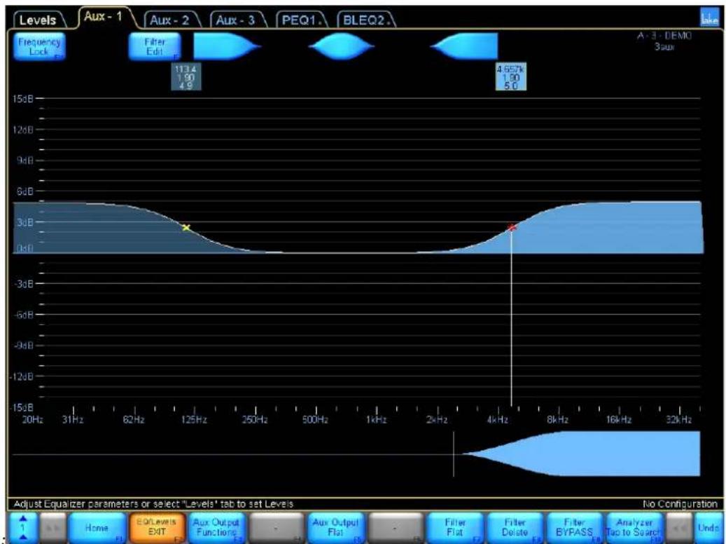
Figure 6-24: Adding a High Shelf and Low Shelf Filter to Aux-1
EQ added to an Aux tab affects only the associated output. Module and Group input EQ (PEQ/BLEQ/GEO) still affects all outputs of the Module.
6.5.4 High-pass and Low-pass Filters
The high-pass and low-pass filter controls are located under the AUX OUTPUT FUNCTIONS submenu.
- With the AUX-1 tab selected, tap AUX OUTPUT FUNCTIONS
- Tap HPF ENABLE then tap LPF ENABLE
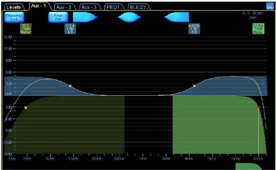
Figure 6-25: Aux Output with HPF and LPF Enabled
To adjust the slope of these filters:
- Tap FILTER SELECT. A scroll bar appears displaying available HPF/LPF types.
- Drag the scroll bar or use the << and >> buttons to view available filters.
- Select the 24dB LINKWITZ/RILEY filter from the scroll bar.
- Tap FILTER SET to activate this filter, then YES to the warning message.

Figure 6-26: Selecting a new filter slope for HPF or LPF

To protect loudspeaker drivers, the audio output for the affected channel is muted momentarily while the settings are changed.
- Select the HPF by tapping its filter box located top left of the screen.
- Select the 18dB BUTTERWORTH filter from the scroll bar.
- Tap FILTER SET, then YES to the warning message.
- Tap AUX OUTPUT EXIT to return to the EQ/LEVELS menu.

Steep high-pass and low-pass filters (48 dB) require more EQ resources than shallower slopes (6 dB).
6.5.5 Auxiliary Output Menu Options
The menu options shown in Figure 6-27 are available when an EQ filter is selected on an Auxiliary Output in the EQ/Levels section of an Auxiliary Output Module.

Figure 6-27: Auxiliary Output Button Bar
A summary of the functions relevant to Auxiliary Outputs is shown below; many are identical to those used on the EQ and XOVER screens.
6.5.5.1 Home
Navigate back to the HOME menu.
6.5.5.2 EQ/Levels EXIT
Navigates to HOME menu, or I/O CONFIG if the current screen accessed via interactive block diagram.
6.5.5.3 Aux Output Functions
Provides EQ preferences, high-pass and low-pass filter options, and OVERLAY COPY/PASTE (and overlay access controls in Designer Mode).
6.5.5.4 Aux Output Flat
Deletes all EQ filters and disables HPF, and LPF filters on the selected auxiliary output channel.
6.5.5.5 Filter Bypass / Filter Insert
Bypasses or inserts a selected EQ filter (not applicable to high-pass and low-pass filters).
6.5.5.6 Filter Flat
Resets the gain of the selected EQ filter to zero. Frequency and bandwidth are unchanged (not applicable for high-pass and low-pass filters).
6.5.5.7 Filter Delete
Deletes the selected EQ filter (not applicable for high-pass and low-pass filters).
6.5.5.8 Filter Edit
Allows keyboard entry of gain, frequency, and bandwidth values for EQ filters (frequency only for high-pass and low-pass filters). Tap the required value at the top of the screen (highlighted in blue) to edit using the on-screen (or external) keyboard.
6.5.5.9 Analyzer Ready / Analyzer Unavailable
Please refer to section 6.3.14 for details on this function.
After selecting AUX OUTPUT FUNCTIONS, the following menu is displayed:

Figure 6-28: Aux Output Functions Menu
6.5.5.10 Home
Navigate back to the HOME menu.
6.5.5.11 Aux Output Properties
Provides a submenu containing EQ Preferences. Access control functions such as AUX OUTPUT HIDE and AUX OUTPUT VIEW ONLY are available only in Designer Mode. Please refer to chapter 19.
6.5.5.12 Aux Output Exit
Navigate back to the main EQ/Levels menu.
6.5.5.13 Filter Select
When selected (orange), a scroll bar is displayed with available high-pass and low-pass filters. Available only when a high-pass or low-pass filter is active and selected; not applicable to EQ filters
6.5.5.14 Filter Set
Available only when a high-pass or low-pass filter is selected on the FILTER SELECT scroll bar.
6.5.5.15 HPF Enable
The high-pass filter is disabled when this button is blue, and enabled when orange.
6.5.5.16 LPF Enable
The low-pass filter is disabled when this button is blue, and enabled when orange.
6.5.5.17 Aux Output Copy
Tapping this button copies the settings of the currently selected output.
6.5.5.18 Aux Output Paste
This button is active only after AUX OUTPUT COPY has been used, and will overwrite the selected auxiliary output with the settings in the copy buffer.
Auxiliary Outputs can be copied and pasted within or between Modules, but the data cannot be pasted on XOVER, PEQ, BLEQ or GEQ screens; the destination channel must be an Auxiliary Output.
7. System Store Recall Menu Reference
The Lake Controller allows the user to store and recall complete system configurations. This enables the same Lake device to be used in entirely different situations, as their complex configurations can be changed in seconds.
7.1 System Store Recall Navigation
From the HOME menu, tap SYSTEM STORE/RECALL. The button bar displays the following options, and a scroll bar also appears containing files and folders.

Figure 7-1: System Store Recall Scroll Bar
The first icon on the system scroll bar is labeled **My Computer**. Selecting this and tapping OPEN will allow you to navigate to folders and files on your hard drive or any removable disk.
The other files shown at the root of this directory are the system configuration files stored from within the Controller software.
If there are many folders or files, drag the scroll bar to the left or right, or tap the << or >> buttons. Most options on the button bar appear gray and are inactive until a folder or file is selected on the scroll bar.
7.2 Shortcut to Data/User Folder
Default software installation of the Lake Controller places a shortcut in the Windows Start menu:
START > PROGRAMS > LAKE CONTROLLER > USER DATA FILES

System files, Module files and LoadLibrary files are located in the My Documents\Lake\Lake Controller 6.x\

Historical files created in versions prior to Lake Controller v6.3 can be located as described below and copied over during migration if required.
For Windows XP, pre Lake Controller v6.3, user files were located at C:\Program Files\Lake\Lake Controller vX.X\data\user.
For Windows 7, pre Lake Controller v6.3, user files were located at C:\Users\username"\AppData\Local\VirtualStore\Program Files\Lake\Lake Controller vX.X\data\user.
7.3 Recall as New System—Open
The function and label of the button depend on whether a folder or file is selected. The button is inactive when neither a file nor folder is selected.
The button is labeled OPEN when a folder is selected.
To open a folder:
- Tap the desired folder icon. The selection is indicated by a yellow border.
- Tap OPEN. Double-tapping the folder icon also opens the folder.
The button is labeled RECALL AS NEW SYSTEM when a file is selected; recalling the file will clear all current settings from the Controller and load the details stored in the file into the associated devices.
To recall a system configuration file as a new system:
- Tap the desired file to recall.
- Tap RECALL AS NEW SYSTEM.
- Confirm the action by tapping the YES button on the warning message.

RECALL AS NEW SYSTEM overwrites current settings in associated Lake devices and will affect audio processing. Presets stored in hardware devices are not overwritten during a system file recall.
7.4 Recall as Subsystem
RECALL AS SUBSYSTEM enables the content of a system configuration file to be added to the current system configuration.
This function adds the Modules, Super Modules, and Groups to your current configuration, or replaces the data if the device is already in use. This function does not automatically arrange icons so they do not overlap. Be careful to either move existing icons before loading a sub-system, or ensure icons are placed appropriately in the stored files.
7.5 Recall Compare
RECALL COMPARE enables comparison of a system configuration file with the system configuration that is currently active in the Lake device. This button is active only when a file is selected.
To compare the current configuration with one stored in a file:
- Tap SYSTEM STORE/RECALL.
- Navigate to the file you wish to compare.
- Tap the file icon to select it.
- Tap RECALL COMPARE.
- Confirm the action by tapping the YES button in the warning message.
This function can help identify any changes that have been made since a file was recalled. Modules with altered data are identified by a red disc behind their normal icon. This indicates that the Lake Controller is out of sync with the device.

Figure 7-2: Module Out of Sync Identification

RECALL COMPARE does not overwrite any data in the device. Audio will not be changed until you tap the button labeled USE DATA IN CONTROLLER.
7.6 Recall as Virtual Sub System (SS)
The RECALL AS VIRTUAL SS button enables you to work on a system file when no physical units are connected. All Frames are seen as virtual. Once the system has been designed, the Virtual Frames can be replaced by physical Frames.
This function adds the Modules, Super Modules and Groups from the selected file to the current system configuration as virtual Modules.
The button will read RECALL AS VIRTUAL SS on screen resolutions of 1024 x 768 or less; the full label RECALL AS VIRTUAL SUB SYSTEM will be displayed on higher resolution screens.

When recalling a Dante-configured system as a Virtual Sub System, all devices receive new default Dante Device names to ensure no conflicts occur if the same system is recalled multiple times. Dante receivers will subscribe to the same Dante channels prior to the virtual recall.
7.7 Store System
The STORE SYSTEM button stores the entire system configuration, including any Dante and AES67 configurations. If a file is selected on the scroll bar, the name of that file will appear in the on-screen keyboard, allowing the file to be overwritten or for a file name variation to be used.
- Tap STORE SYSTEM.
- Confirm the action by tapping the YES button in the warning message.

If the selected file is set to read only, the STORE SYSTEM function is inactive (gray).
7.8 Store Subsystem
The STORE SUBSYSTEM button stores the selected Modules, Super Modules, and Groups as a subsystem. Only the data from the selected Modules, including Group assignments, will be stored in the file.
- Navigate the file system, and tap the desired destination folder to select it.
- Select the required Modules, Super Modules, and Group icons.
- Tap STORE SUBSYSTEM.
- Enter the file name using the on-screen keyboard (or an external keyboard).
- Tap OK.
The scroll bar displays the new file.
7.9 File Utilities
This button provides a submenu containing further functions that manage files and folders from within the Lake Controller.
7.9.1 Open
This button is active only when a folder is selected. Tap Open to open the selected folder.
7.9.2 Read Only
This function protects important files from being accidentally overwritten or deleted and is active only when a file is selected. The currently selected file's status is identified by the color of the Read Only button:
▶ ORANGE - the selected file is set to Read Only.
BLUE - the selected file is not set to Read Only.
To change the status of a file:
- Tap a file from the scroll bar to select it.
- Tap READ ONLY to toggle the function on (orange) and off (blue).
7.9.3 Rename
This button changes the name of a file or folder.
- Tap the file/folder from the scroll bar.
- Tap RENAME.
- Enter the new name using the on-screen keyboard (or an external keyboard).
- Tap OK.
7.9.4 Delete
This button is active only when a file or folder is selected. When a file is selected, this function is not available if the file is set to Read Only.
To delete a file or folder:
- Tap a file or folder to select it.
- Tap DELETE.
- Confirm the action by tapping YES in the warning message.

Deletion of a file is permanent and cannot be restored using the UNDO function.
7.9.5 New Folder
This button creates a new folder in the current directory. To create a new folder:
- Navigate to the directory where the NEW FOLDER will reside.
- Tap NEW FOLDER.
- Enter the NEW FOLDER name using the on-screen (or external) keyboard.
- Tap OK.
7.10 System Presets
The SYSTEM PRESETS function allows entire system configurations to be stored in a network of Lake devices. This enables fast retrieval and switching of configurations as there is minimal data being sent between the Controller and the devices.

Figure 7-3: System Presets Scroll Bar
System Presets are stored in each device and retrieved either via the Controller software (described in this section), via the front panel of the device, or via the relevant Preset Manager utility.
The Preset icon will contain a lock icon if the Preset is locked, and/or a crossed tag icon if the Preset is set to Exclude Labels when the Preset is recalled. For further information on using the Preset Manager Utilities, please refer to chapter 28.
7.10.1 Storing a System Preset in Multiple Devices
To store the current system configuration in multiple Lake devices:
- Set up the configuration as required.
- From HOME, tap SYSTEM STORE/RECALL, then tap STORE SYSTEM. This ensures that you have a backup of the exact data, which will be stored as a preset in the hardware.
- Tap SYSTEM PRESETS.
- Tap the Group/Module icons that you wish to be stored as part of the system preset. Icons turn green to indicate selection.
If you require all Frames in your system configuration to be stored as a system preset, tap a Module from each Frame, or if you are using Groups, tap a Group that contains all Frames, as shown in Figure 7-4. To deselect a Frame or Group, tap the icon again.

Figure 7-4: Selecting Multiple Frames for Preset Store via Group Icon
After making the desired Module selections:
- Tap on an empty preset location from the scroll bar (for example, Preset 1). The button labeled STORE WITH NEW NAME will be activated.
- Tap STORE WITH NEW NAME.
- Enter a preset name using the on-screen (or external) keyboard, and tap OK.
7.102 Recalling a System Preset into Multiple Devices
To recall a system preset into multiple Lake devices:
- From HOME, tap SYSTEM STORE/RECALL, then tap SYSTEM PRESETS.
- Select each Frame you wish to recall the preset into by tapping Module or Groups icons. Selected Frames are identified by green icons.
- Tap the required preset on the scroll bar.
- Tap RECALL and then OK to the warning messages.
The audio will change quickly, but the Controller will not synchronize with the network until you exit the SYSTEM PRESET menu. A flashing warning message confirms this.
This enables quick comparison between different configurations without the need to synchronize the Controller after each preset is recalled

Figure 7-5: System Presets Warning Message
The system configuration name of the preset last recalled will flash at the bottom right of the screen.
Once the required system preset has been recalled, tap HOME or SYSTEM PRESET EXIT to synchronize the Controller with the new settings that have been recalled into the devices.

Individual Frame presets can also be recalled from the front panel of each Lake device.

For LM Series devices, if the preset recall changes the configuration between Contour and Mesa configurations, a warning will be displayed and Modules returned to the scroll bar.
7.10.3 Quick System Preset Recall and Comparison
Quick Recall mode instantly recalls each system preset into all selected Frames when the preset location on the scroll bar is tapped. No confirmation messages are displayed while in this mode, and all other preset functions are disabled.
To enable fast recall/comparison of SYSTEM PRESETS:
- From HOME, tap SYSTEM STORE/RECALL, then tap SYSTEM PRESETS.
- Select each Frame you wish to recall the preset into by tapping Module or Groups icons. Selected Frames are identified by a green icon.
- Tap QUICK RECALL. Orange equals active; blue equals inactive.
- Tap a preset location from the scroll bar.
- Repeat the previous step to compare with other SYSTEM PRESETS.

Confirmation/warning messages are not displayed in Quick Recall (except for configuration between Contour & Mesa). Tapping the preset location immediately recalls the selected system preset.
7.10.4 Storing over an Existing Preset
Follow the steps shown in section 7.10.1, but select a system preset location that is already used and tap STORE instead of NEW STORE. The data in the preset location of the selected Frames will be replaced by the current system configuration.
7.10.5 Clearing a Preset Location
To clear a system preset location from multiple Lake devices:
- From HOME, tap SYSTEM STORE/RECALL, then tap SYSTEM PRESETS.
- Select each Frame you wish to clear the preset from by tapping Module or Groups icons. Selected Frames are identified by a green icon.
- Tap the preset location that you wish to clear from the scroll bar.
- Tap CLEAR, then OK to the warning messages.
7.10.6 Preset Mismatch
If one or more of the selected Frames contains a different configuration in a particular preset location, PRESET MISMATCH displays as the name for that system preset location.
A mismatch occurs if different configurations are stored separately in the same Preset location across different Lake devices, and these devices are selected together in the SYSTEM PRESET menu.
To correct a preset mismatch status, either empty the preset location using the CLEAR function, or use the STORE WITH NEW NAME function to store the data of the current system configuration into all selected Frames.
The RECALL and STORE buttons will be disabled when a location is selected for multiple Frames that contain a preset mismatch.
8. Modules Menu Reference
From the HOME menu, tap MODULES. The Modules menu and scroll bar appear as shown below. The scroll bar shows all Lake devices connected to the network.

Figure 8-1: Modules Menu and Scroll Bar
The scroll bar pictured above displays the following (from left to right):
▶ Virtual Frames folder, containing all device configurations for creating systems offline ▶ Two Modules of a PLM 14000 that are available on the network but not used in the current system ▶ Two Modules of a Lake LM 26, and four Modules of a D200:4L that are in use in the current system
If many devices are available, tap and drag the scroll bar to the left/right, or tap the blue << or >> buttons. Most options on the button bar appear gray (inactive) until a Module is placed from the scroll bar onto the Main page. If the labels on the scroll bar are selected for a module that is used in the system, the modules on the work area will be highlighted.

Devices are sorted by product type, followed by alphabetical Frame name order on the Module scroll bar.
8.1 EQ/Levels
Navigate to the Modules menu, and tap the EQ/Levels button to display the Parametric EQ, Graphic EQ, XOVER, and LEVELS screens for the selected Module. This function is active only when a Module has been selected in the work area. For more information, please refer to section 6.1.
8.2 I/O Config
The I/O CONFIG screen provides access to I/O Configuration, Technical Information and Input Router Mutes; it also provides an interactive signal path that can be used to directly navigate to the LEVELS/EQ/XOVER screens, and the ability to reset or configure the device.
To view the I/O CONFIG screen:
- From HOME, access the MODULES menu.
- Select a Module icon in the work area, and tap I/O CONFIG. The I/O CONFIG button is active only when a Module is selected in the work area.
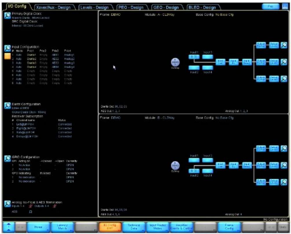
Figure 8-2: LM 44 I/O Configuration Screen
Figure 8-2 shows the I/O CONFIG page for an LM 44. The sections that follow describe each screen/function in further detail.
I/O Config settings are stored in system configuration files and in Frame/system presets. I/O Config parameters are transferred during the Frame Replace function.

I/O Config parameters are not stored, recalled, copied, or pasted via Module or base configuration files.
8.2.1 Digital Clock Configuration
LM, PLM+ and D Series devices provide two digital clock domains:
The Primary Digital Clock locks to sample rates of 48, 96, or 192 kHz. The Sample Rate Converter (SRC) Clock locks to 44.1, 48, 88.2, 96, 176.4, and 192 kHz.
The PLM Series provides a single digital clock, equivalent to the SRC Clock on PLM+, LM and D Series devices. The MY8-LAKE provides a Primary clock fixed to multiples of 48 kHz and an SRC clock fixed to multiples of 44.1 kHz. The LM Series digital clock screens will be used in the examples below.
To access the Digital Clock Configuration window, tap the zoom button located at the top left of the I/O CONFIG page.

Figure 8-3: LM 44 Digital Clock Summary - I/O Configuration
After tapping the zoom button shown in Figure 8-3 the following screen is displayed:

Figure 8-4: LM 44 Digital Clock Configuration Screen
8.2.1.1 Auto Detection
By default, the most appropriate digital clocks are automatically detected. The first valid clock in the order of the list shown below is chosen to configure the Primary Clock as 48/96/192 kHz, and the SRC Clock as 44.1/88.2/176.4 kHz.
- Host Word Clock (MY8-LAKE Only)
- AES1 (In 1+2)
- AES2 (In 3+4)
- AES3 (In 5+6)
- AES4 (In 7+8)
- Internal Clock (88.2 or 96 kHz)
If a clock signal is not relevant for the product, or is not connected, or the signal has been temporarily lost, the automatic detection process chooses the next valid clock source from the list, provided it matches the selected base rate (either 44.1 or 48 kHz). If a valid clock source is detected from a source which is higher on the list than the currently selected source, then the clock will switch to use the higher priority source.

The SRC Clock has two options for automatic clock detection: Auto 44 and Auto 48. These settings provide automatic detection within a particular range of frequencies (either 44.1/88.2/176.4 kHz or 48/96/192 kHz).
8.2.1.2 Manual Config
For a fixed configuration, it is possible to fix the clock selection independently for each digital clock.
- Tap the required clock from the CLOCK SOURCE SELECTOR at the bottom of the DIGITAL CLOCK CONFIGURATION window.
- Tap the icon showing the currently selected clock under the relevant clock heading in the top-left (Primary) or top-right (SRC) sections of the window.
The larger icon in each of the windows shows the selected clock, and the associated text confirms the rates that are available when using this clock for either inputs or outputs.

Manual configuration is necessary when two asynchronous base-48 kHz clock domains are connected to a device. In this scenario, ensure that each digital clock, digital input and digital output is manually forced to lock to the appropriate clock domain.
8.2.1.3 Dante Clock (not applicable for MY8-LAKE)
When Dante is enabled on a Lake device, the Primary Clock is used for Dante purposes. One Dante device will be allocated as the Dante Master, and all other devices will be Dante Slaves. The Dante master is selected automatically following these priorities:
- Preferred Dante master (via Dante Configuration screen)
- Devices with an external BNC Word Clock input
- Devices with other external clocks (e.g. AES Inputs)
- Hardware-based devices
- Software-based devices, e.g. Dante Virtual Soundcard
Where there is no distinguishing feature for a device to be selected (for example, all devices have a BNC Word Clock connected, or multiple devices have an AES signal), then Dante uses the device with the lowest Mac Address as a unique distinguishing feature. However, if a Frame has been the Dante master for more than one minute, its priority is elevated to prevent a master transition based on Mac address alone.
The Dante Master may lock to an external clock via the Primary Clock as shown in the example below. If the Frame requires locking to another signal type, the SRC Clock should be used. The example below shows how two differing AES signals can be connected to one Lake device, with Dante locking to the Primary Clock's AES signal.

Figure 8-5: Primary Clock as Dante Master
Other Lake devices on the network that have Dante enabled will be Dante slaves, and the clock will report that it is overridden by Dante, as shown in Figure 8-6. Any other 96 kHz signal, or 44.1 kHz based signal should be locked using the SRC Clock (applicable for LM Series only).

Figure 8-6: Primary Clock as Dante Slave
For PLM+ and D Series with Dante enabled, the Primary Clock will always lock to Dante; the device can still be a Dante master, but the internal clock will be used to lock the Primary Clock. Any external digital input must use the Sample Rate Converter Clock.
8.2.1.4 Host Clock (MY8-LAKE only)
The highest priority auto-clock selection for the MY8-LAKE device is the Host Clock as shown in section 8.2.1.1. For the MY8-LAKE device, the Primary Clock can only lock to a source operating in multiples of 48 kHz, and the Sample Rate Converter Clock can only lock to a source operating in multiples of 44.1 kHz.
Ensure that AES & Host clocks operating at the same base-rate (e.g. multiples of 48 kHz) are in-phase to avoid any clock slipping errors.
8.2.2 Input Configuration
Each input router may be configured to use any available input source. Sources include AES/EBU digital inputs, Dante inputs, analog inputs, and Host digital inputs (MY8-LAKE only).
To access the input configuration, tap the zoom button, or any area of the INPUT CONFIGURATION summary text on the I/O CONFIG screen shown in Figure 8-7, except the enable button below the magnifying glass. Clicking this will enable the Input Router Configuration Overview, making it easy to see how all input routers and the four priorities are configured. The selected channel will be highlighted in orange. The selection to have Input Router Configuration Overview enabled will be stored when going between different frames as well between Lake Controller sessions. To disable, just click the enable button.
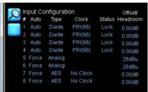

Figure 8-7: Input Configuration Active Input and Summary view on I/O Config screen
After tapping the zoom button or anywhere on the text, an INPUT CONFIGURATION screen similar to that shown in Figure 8-8 will be displayed. The number of available input routers varies depending on the product type.

Figure 8-8: LM 44 Input Configuration Screen
8.2.2.1 Autoselect
The input auto-selection feature enables the set up of a redundant system. The device will attempt to use the first signal; if the first signal is unavailable it will try the second, third, or fourth signal.
By default Priority 1 is set to Dante Receivers, Priority 2 is empty, Priority 3 is AES and Priority 4 is Analog.
8.2.2.2 Force
This feature forces the input to the selected input, regardless of whether a valid signal is present.
8.2.2.3 Input Selector Search Filters
▶AES displays the available AES input signals ▶DANTE displays the available DANTE input signals ▶HOST displays the available HOST input signals ▶ANALOG displays the available ANALOG input signals
- SEARCH filters the available input signals based on text that is entered
8.2.2.4 Input Configuration Display Details View
After tapping the DISPLAY DETAILS button, a screen similar to Figure 8-9 is displayed.
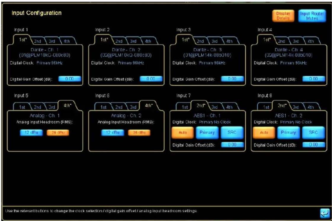
Figure 8-9: LM 44 Input Configuration - Display Details View
8.2.2.5 AES Input Options
These options are available only for a Lake device with two clock domains.
▶ AUTO chooses the clock most relevant to the incoming digital signal. For example, if the input signal is 48 kHz, the Primary Clock will be selected; if the input is 44.1 kHz, the SRC Clock will be selected. The default is Primary Clock if a digital input signal is not present. ▶ PRIMARY forces use of the Primary Clock, regardless of whether the clock rate matches the incoming signal rate. ▶ SRC forces use of the SRC Clock, regardless of whether the clock and incoming signal rates match.

When both the Primary and SRC clocks are manually locked to separate asynchronous base-48 kHz domains, it is important to manually select which clock domain each AES input should lock to. Leaving as AUTO may result in clock slipping errors.
8.2.2.6 Analog Input Options
For analog inputs, ANALOG INPUT HEADROOM (RMS) provides a two-way toggle for selecting 12 or 26 dBu. Tap the required headroom level to set the maximum RMS level for the input.
PLM+ and D Series amplifiers are fixed to 26 dBu RMS.
8.2.2.7 Digital Gain Offset
The Digital Gain Offset represents the amount of gain increase or reduction in dB that will be applied to the digital input signal to allow seamless transition between all input types.
As levels of digital and analog signal vary, the Digital Gain Offset can be used to adjust the digital input signal level to match the analog input signal level.
This can be used in conjunction with AUTOSELECT to provide an automatic analog backup to the incoming digital audio. Separate values are provided for AES and CobraNet.
To change an offset, tap the value that you wish to change and enter a new value using the on-screen (or external) keyboard. These offsets are shown on the I/O CONFIG summary.

When aligning analog and digital signals using the Digital Gain Offset setting, the +4 dBu Reference meter mode should be used to ensure levels are matched with a common internal reference.
8.2.2.8 Input Router Mutes
Tapping the INPUT ROUTER MUTES button from the Input Configuration screen will display the Input Router Mutes floating tool bar.
Please refer to section 8.2.11 for further information.
8.2.3 GPIO Configuration (LM Series Only)
For LM Series devices, a summary of the current GPIO settings is displayed on the I/O CONFIG screen. Please also refer to the LM Series Operation Manual for additional information on the GPIO feature.
GPIO allows external interface with alarm and monitoring systems, providing basic functionality such as muting, power control, preset recall and fault monitoring. GPI (input) allows external devices to control certain features of LM Series devices as listed in Table 8-1. GPO (output) enables the LM Series device to report certain statuses and faults to external devices as summarized in Table 8-1.
Tapping the summary text or associated zoom button on the I/O CONFIG screen will display the screen shown in Figure 8-10.

Figure 8-10: LM Series GPIO Configuration Screen
The screen is split into two sections - the top section provides options for two General Purpose Input (GPI) actions, and the bottom section provides actions for two General Purpose Output (GPO) commands.
8.2.3.1 GPI Options and Configuration (LM Series Only)
Table 8-1 lists the options available for General Purpose Input (GPI). These options can be set independently for a transition from closed > open and from open > closed.
To change the action that occurs for a GPI command:
- Tap the 'Acting On' cell for the required GPI command
- Select the required option from the pop-up window.
- Tap the corresponding 'Action when transition to CLOSED' cell
- Select the required option from the pop-up window that is displayed
- Tap the corresponding 'Action when transition to OPEN'
- Select the required option from the pop-up window that is displayed.
8.2.3.2 GPO Options and Configuration (LM Series Only)
Table 8-1 lists the options available for General Purpose Output (GPO). The state when closed is user-defined and the state when open is set to the opposite value automatically.
| Indicating State when Closed | |
| Protective Mute State | 1. Muted2. Unmuted |
| Standby State | 1. Standby2. On |
| Fault | 1. No Fault2. Any Fault |
| Ready | 1. Ready2. Not Ready |
| No Indication - |
Table 8-1: GPO Options
To change the action that occurs for a GPO command:
- Tap the 'Indicating' cell for GPO1 or GPO2.
- Select the required option from the pop-up window.
- Tap the corresponding 'State when CLOSED' cell.
- Select the required option from the pop-up window that is displayed. 'State when OPEN' will be set automatically.
8.2.4 Breaker Emulation Limiter (BEL™) - PLM 20000Q, PLM+ and D Series
Three types of breaker are available (Conservative, Fast and Universal) as shown in Figure 8-11; each breaker behaves accordingly when the nominal current is reached. Breaker characteristics that a product does not support are grayed out. These can still be selected, but the product will automatically use a characteristic that it supports. The actual characteristic in use is displayed within brackets [] to the right of the selection.
The Conservative breaker type does not allow the current to exceed the nominal current value.
The Fast and Universal breaker types allow the current to exceed the nominal current value, but calculate how the temperature of the breaker is affected. The allowed current is decreased when necessary to reduce breaker temperature; the Universal breaker type allows a higher temperature before the allowed current is reduced.
The meters on the right of the screen display Volts RMS and Amps RMS. The Volts RMS meter is gray (voltage OK) when the voltage is between 80 and 265 V. The meter turns orange (voltage warning) when between 65 V and 80 V and UVL (Under Voltage Limiter) may engage. It turns red (voltage fault) when below 65 V or above 265 V and the audio will be muted.
UVL is not applicable for D Series 10:4L and D 20:4L models.

Figure 8-11: Breaker Emulation Limiter Screen
To change the nominal current, tap the blue edit value and enter a value between 1.0 A and 32.0 A (5.0 A and 32.0 A for PLM 20000Q). The actual value is displayed in brackets to the right of the desired editable value, and varies depending on the minimum and maximum capability of the amplifier model.
To change the currently selected breaker type, tap the required breaker on the scrolling bar at the bottom of the screen then tap again in the Breaker Type box at the top of the screen.
| Model Current (Amps) Fuse Options Available | ||
| D 200:4L 5-32 Conservative, Fast, Universal | ||
| D 120:4L 5-25 Conservative, Fast, Universal | ||
| D 80:4L 5-15 Conservative, Fast, Universal | ||
| D 40:4L 2-15 Conservative, Fast, Universal | ||
| D 20:4L | 1-7 | Universal |
| D 10:4L | 1-7 | Universal |
| PLM+ 5K44 | 2-15 | Conservative, Fast, Universal |
| PLM+ 12K44 | 5-25 | Conservative, Fast, Universal |
| PLM+ 20K44 | 5-32 | Conservative, Fast, Universal |
| PLM 20000Q | 5-32 | Conservative, Fast, Universal |
Table 8-2: Nominal current range and fuse options by product
8.2.5 Dante Configuration (not applicable for MY8-LAKE)
The Dante Configuration (named "Dante and AES67 Configuration" for all AES67 enabled models) summary on the I/O CONFIG screen reports either the Global Dante Clock Sample Rate, or advises that Dante is disabled. When disabled, the device does not support transmitting or receiving any networked audio. It additionally lists the assigned receiver subscriptions and associated sample rate and status.
Further information on Dante settings can be accessed by tapping the zoom button or the associated text. A screen similar to that shown in Figure 8-12 will be displayed. All settings available under Dante Configuration are stored in System files, Frame Presets and are set on any Frame Replace/BATCH REPLACE operation.
To configure the device for Dante dual redundant operation, navigate to the TECHNICAL DATA screen via the I/O CONFIG menu and enable the Dual Redundancy option. This change will require a power cycle of the device; please refer to section 8.2.10.4.
8.2.5.1 Device Tab
Tapping the zoom button labeled DANTE CONFIGURATION displays the Dante Configuration > Device tab, with Dante disabled by default:

Figure 8-12: Dante is disabled by default
To enable Dante, tap the button labelled Dante Disabled; the button turns orange and now reads Dante Enabled and other functions become available. Enabling Dante will enable the device for network audio input and output.

Dante can be enabled globally for all Dante-capable devices in the current system configuration via Home > All > Global Info > Events & Control > Control > Global Dante Enabled control.

AES67 can be enabled globally for all AES67-capable devices in the current system configuration via Home > All > Global Info > Events & Control > Control > Global AES67 Enabled control.
Preferred Clock Master
This option identifies this device as the preferred clock master device for the Dante network. To enable this device as the Preferred Clock Master, tap this button. Any AES67 enabled devices can also act as AES67 clock master. The AES67 clock master can be seen in Dante Controller. For a device to be Clock Master on either Dante or AES67, the device cannot be in Slave Only mode.
If this button is disabled when Dante is Enabled, the device is set to Dante Slave Only mode. The Dante Slave Only mode can be viewed/edited via the Technical Data screen - refer to section 8.2.10.
Sample Rate
Dante may operate at either 48 kHz or 96 kHz; tap the appropriate button to select the preferred sample rate. For products supporting AES67, when AES67 mode is enabled, the device can only operate at 48 kHz.
Dante Device Name
The Copy Frame Label button copies the Frame label into the Dante Device Name parameter for this device; after tapping this button, click OK on the on-screen keyboard to confirm the change. Alternatively the keyboard icon may be selected to display the keyboard for manual Dante Device Name entry.

If the Dante Device Name is changed after another device has already subscribed using the previous name, the existing audio connection will be lost and the other device will need to subscribe again.

When recalling a system file created before Lake Controller v6.1, the legacy DLP-XX-XX device names are restored to retain Dante subscriptions.
This parameter is synchronized between the Lake Controller and the Dante Controller. This can also be done for all frames in the system from the Global Control tab.
Device Latency Options
This latency is additional Dante-specific latency used to ensure uninterrupted digital audio. The latency is added to the normal latency of your chosen signal path and Module type.
The following latencies are available dependent on the device:
LM, PLM+ and D Series (Gigabit Ethernet): 0.25ms / 0.50ms / 1.00ms / 2.00ms / 5.00ms
PLM Series (100 Mbit Ethernet): 1.00ms / 2.00ms / 5.00ms
This parameter is synchronized between the Lake Controller and the Dante Controller.

Dante latency values changed in Lake Controller v6.1. When recalling a system file created before Lake Controller v6.1, previous Dante latency options will be converted, rounding up to the nearest latency value.
These minimum receive latency options are provided to allow flexibility depending on the network complexity and architecture. Higher latency reduces the risk of audio glitches due to audio packets being delayed via the network, and is therefore recommended for complex networks containing many hops, or in circumstances where a small delay is irrelevant and reliability is paramount.

Using Ethernet switches without Quality of Service (QoS) is not recommended. If QoS is unavailable, use the 5 ms latency option on all devices to reduce the risk of audio glitches.
As with all Dante devices, Multicast flows are automatically set to a minimum of 1 ms. If a transmitter does not support the latency set on the receiver (i.e. it can't guarantee delivery within the required latency), Dante will increase the latency to the lowest setting supported by the transmitter.
For supported devices, it is possible to see a Latency tab in Dante Controller displaying histograms of audio packet latency for each transmitter that the device is subscribed to.
8.2.5.2 Receive Tab
To configure the Dante Receivers for the selected device, tap the RECEIVE tab and assign channels from another Dante device which will be used as inputs for this device.
To assign Dante Receive channels to a device:
- Tap the RECEIVE tab
- Select a device from the DEVICES scrollbar
- Tap a channel on the Channels scrollbar then place the selected channel in a Receiver location at the top of the screen.
This parameter is synchronized between the Lake Controller and the Dante Controller. All Dante receive configurations (subscriptions) can also be done in Dante Controller. Starting subscriptions on AES67 channels can only be done from Dante Controller. It is however possible to see the AES67 transmitter device in Lake Controller, but it is not possible to do the actual subscription.
Once an AES67 subscription is done (from Dante Controller), it is possible to see the active subscription in the Dante Receiver in Lake Controller.
Active AES67 subscriptions in the Dante Receivers can also be removed or replaced with Dante Subscriptions from Lake Controller.

Channels that cannot be subscribed to due to sample rate differences or other reasons are displayed greyed out after those which can be subscribed.

When Dante is locked for the receiving channel, an asterisk (*) is shown next to the Receiver number as shown in Figure 8-13.

Figure 8-13: LM Series Dante Receive
When Dante is enabled, the INPUT CONFIGURATION screen provides an option to view the assigned Dante Receivers as configured on the DANTE CONFIGURATION > RECEIVE tab. To assign a Dante Receive channel to an available Input Priority, tap on an icon on the scrollbar and place it in an Input Priority tab. A channel that is grayed-out is operating at a different sample rate compared to the selected device; the device will be unable to lock to this channel until both the channel and the device are operating at the same sample rate.

Figure 8-14: Dante Receivers on Input Configuration scroll bar

If Audinate 'Dante ConMon' and 'Dante Discovery' services are not running correctly, the Dante Receive Config is disabled and a warning is displayed at the top-right of the Receive tab. Verify via Control Panel Items \ Administrative Tools \ Services; restart if required.
| PRODUCT | DANTE IN | DANTE OUT | DUAL REDUNDANCY | AES67 SUPPORT |
| Lake LM Series 4 channels 8 channels YES NO | ||||
| PLM Series 2 channels | 2 channels(unprocessed audio only) | YES NO | ||
| PLM+ Series 8 channels | 8 channels(unprocessed audio only) | YES YES | ||
| D Series 8 channels | 8 channels(unprocessed audio only) | YES YES | ||
| MY8-LAKE | N/A | N/A | N/A | N/A |
Table 8-3: Dante Input / Output Channels and AES67 support by Product
8.2.5.3 Transmit Tab
When Dante is enabled, by default the device will receive networked audio but will not transmit audio. Transmission is disabled in order to prevent unnecessary network traffic and unused channels on the INPUT CONFIGURATION screen of all other devices on the network.
To transmit Dante channels from a device:
- Tap the DANTE DISABLED button on the DEVICE tab
- Tap the TRANSMIT tab
- Tap the TRANSMIT OUTPUTS button
Transmit channels from this device will now appear on the list of all available Dante channels on the network.

Dante Transmit can be enabled globally for all Dante-enabled devices in the current system configuration via Home > All > Global Info > Events & Control > Control > Global Dante Transmit Enabled control.

Figure 8-15: PLM+ and D Series Dante Transmit Enabled
When the TRANSMIT OUTPUTS button is active (orange), all Dante channels will be advertised on the Dante audio network as available channels for any other Dante receiver to use for its inputs. In addition, this screen provides MULTI/UNI options for each channel, and output channel labeling functions as shown in Figure 8-16. To the right is AES67 transmit information available for applicable models. AES67 transmit flows are configured in Dante Controller and are view-only in Lake Controller.

Figure 8-16: Options and Labels for Dante Outputs
Multicast / Unicast Setting
The MULTI/UNI options provide the ability to identify whether each channel will be configured as multicast (i.e., many devices receive a connection to the same audio flow), or configured as unicast (i.e., each device receives a separate point-to-point audio flow).

Use alphanumeric characters (uppercase or lowercase) and the "-" character only. DO NOT use any other characters, especially @ . =

It is important to use Multicast when a particular channel is distributed to three or more receivers; this ensures optimal bandwidth usage and Dante network stability.
Set to multicast before enabling the transmit outputs option if it is known that three or more receivers will subscribe to this channel. AES67 transmit flows are Multicast only.
This parameter is synchronized between the Lake Controller and the Dante Controller.
Output Channel Labeling
Tapping the keyboard button to the right of the UNI button will display the on-screen keyboard allowing up to a 31-character name to be entered for this Dante channel.

Use alphanumeric characters (uppercase or lowercase) and the "-" character only. DO NOT use any other characters, especially @ . =
Entry of appropriate and meaningful channel labels on all devices is recommended before configuring system routing. If a Dante device name or output channel label is changed on a Dante transmitter after routing to receiving devices, the channel must be disconnected and re-routed on the receiver/s to reestablish a valid connection.
For additional information regarding Dante configuration, please refer to chapter 8.2.
As Dante uses standard Ethernet for digital audio transmission, there are certain guidelines and rules which must be adhered to for successful implementation. Please refer to section 3.6 for further details, along with the Dante literature included with the Lake Controller software installation.
Dante Dual Redundancy
For LM, PLM and PLM+ Series, dual redundancy is OFF by default; navigate to the TECHNICAL DATA screen via the I/O CONFIG menu and enable if required.
For D Series, dual redundancy is ON by default; navigate to the TECHNICAL DATA screen via the I/O CONFIG menu and disable if not required.
This change requires power cycle of the device to complete; please refer to section 8.2.10.4.

Dual redundancy status is also displayed on the Front Panel of the device (except D Series)
8.2.6 Iso-Float Status & AES Termination
When an online device is selected the button reads Analog Iso-Float & AES Termination. When any virtual device or an MY8-LAKE device is selected then neither option is available.
The Analog Iso-Float & AES Termination Status screen is accessed by tapping the zoom button to the left of this summary as shown in Figure 8-17.
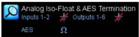
Figure 8-17: Analog Iso-Float & AES Termination Summary
Software control of the Analog Iso-Float is available for Lake-enabled amplifiers, along with separate control for the analog outputs on LM Series devices. AES Termination is available for all devices except MY8-LAKE. The current status is identified by an orange button as shown in Figure 8-18.

Figure 8-18: LM Series Analog Iso-Float & AES Termination Status
8.2.7 Input Mix Summary and Input Mixers/Switches
Input mix summaries and switches are shown on the I/O CONFIG page as part of the interactive signal path for each Module.
8.2.7.1 Input Mix Summary
The block diagram for each Module shows a summary of the connected inputs and associated gain settings. The example in Figure 8-19 shows a LM Series Mesa Module.
![graph LR A["Input 1 -3.20"] --> B["Input 3 1.20"] C["Input 2 0.30"] --> D["Input 4"] E["Input 5"] --> F["Input 6"] G["Input 7"] --> H["Input Gain"] I["Input 8"] --> H H --> J["Input EQ"] J --> K["Input Delay"] K --> L["HPF/LPF"] L --> M["Output Levels"] N["Anlg Out: 7"] --> O["Dig Out: 7"]](/content/2026/07/1419186/images/cc8aad6f06475c587712d55bd4bec2a10766e77ab3932eb694c9de754cfa26aa.jpg)
Figure 8-19: LM Series Mesa Module Input Mix Summary and Interactive Block Diagram
8.2.7.2 Input Mixer
The Input Mixer provides the ability to mix incoming audio channels as defined by the Input Configuration, and can be accessed from two locations:
▶ Tap the Input Mix Summary from I/O CONFIG ▶ Tap the INPUT MIXER zoom button from LEVELS
The input mixer provides gain faders and ON/OFF connection buttons as shown in Figure 8-20.

Figure 8-20: Module Input Mixer
To connect/disconnect an input, tap the button labeled ON/OFF or drag the fader. The total Module input mix is shown on the far right of the Input Mixer window.
For Dante inputs, the receiver input channel label is displayed below the ON button.
Input +4dBu Button
Tap the INPUT +4dBu button to view the physical input signal meter relative to +4 dBu. Tap the button again to return to the default Digital Clip (DClip) view.
The DClip metering mode shows the audio level prior to any gain adjustment (input headroom, or digital gain offset), and indicates when the A/D converters will clip. The +4 dBu metering mode shows the audio level after any gain adjustment, and is useful for comparing levels of different input signals prior to processing.
This is a global function; all physical input meters throughout the system display the reference selected here.
Auxiliary Input Toggle Switch
An auxiliary channel is available on the following Module types:
▶ Classic 2-Way + 1-Auxiliary Outputs (CL2w+1a) ▶ Classic 3-Way + 1-Auxiliary Outputs (CL3w+1a) ▶ Linear Phase Classic 2-Way + 1-Auxiliary Outputs (LP2w+1a)
The interactive block diagram for these Modules types looks similar to that shown in Figure 8-21.
![graph TD A["Input 1 0.00"] --> B["Input Gain"] C["Input 2"] --> D["Input EQ"] E["Input 3"] --> B F["Input 4"] --> D B --> G["Post EQ"] D --> G G --> H["Output EQ/Xvr"] G --> I["Output Levels"] G --> J["Output EQ/Xvr"] G --> K["Output Levels"] H --> L["Output EQ/Xvr"] I --> M["Output Levels"] J --> N…](/content/2026/07/1419186/images/368ef2333ca19347d7f3ba4ce0310b3ba273c06e066b1250e65f3260ed788886.jpg)
Figure 8-21: 2-Way + 1-Auxiliary Outputs Block Diagram and Input Mixers
These Module types provide a separate input selector for the auxiliary channel. This allows the auxiliary channel to be sourced independently of the crossover, or from the same post-input EQ signal.

The input EQ (PEQ/BLEQ/GEQ) overlays will also affect the auxiliary output channel when the input switch is set as shown in Figure 8-21.
Simplified View Input Toggle (MY8-LAKE Mesa Mode Only)
For an MY8-LAKE in Mesa Mode, the default I/O configuration view is set to Simplified View. In this view, either the Host output or AES input can be selected as the source input signal. The Input Mixer and Input Router are not available; the input selector toggles between Host Output and AES Input.
![graph LR A["Host Out Ch 1"] --> B["Input Gain"] C["AES CH 1"] --> B B --> D["Input EQ"] D --> E["Input Delta"]](/content/2026/07/1419186/images/a8541bb9a465503933c0c3de0e9ce4b285895195eea4cef9b11b7d05009c1068.jpg)
Figure 8-22: MY8-LAKE Simplified View Input Mixer
Please refer to section 22.4 for further information on Simplified View.
8.2.8 Output Configuration
The Output Configuration window is displayed either after tapping the zoom button located to the right of each output on the right side of the I/O CONFIG page, or after loading a Module file. The automatic display of the Output Configuration following a Module Recall can be enabled or disabled from this screen. A summary of the output connections for each Module appears at the bottom of each Module cell on the I/O CONFIG page.
![graph LR A["Input 1 0.00"] --> B["Post EQ"] C["Input 2"] --> B D["Input 3"] --> B E["Input 4"] --> B B --> F["Output EQ/Xvr"] F --> G["Output Levels"] G --> H["Search Icon"]](/content/2026/07/1419186/images/930dfed574af16e2996a03883f0ed75c326f2e23e30784c13fff9448056ecd79.jpg)
Figure 8-23: Output Configuration Zoom Button
After tapping any of these zoom buttons, an Output Configuration window is displayed, which looks similar to that shown in Figure 8-24. The options and number of channels available on this screen depend on the type of Lake device currently selected.
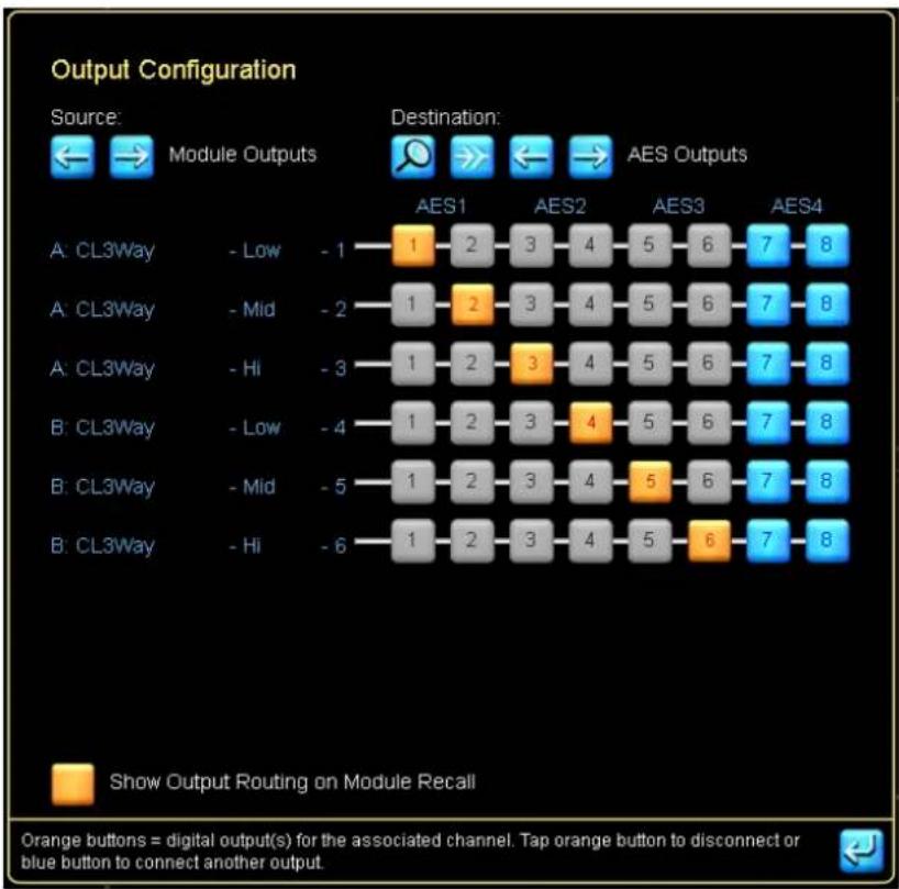
Figure 8-24: Output Configuration Screen
The left side of the screen lists the output channels for each Module. The orange numbered blocks denote the output/s from which the signal will be sent. The same audio channel can be sent from multiple outputs, but each digital output can contain only one channel of audio.
The following sections describe the options for SOURCE and DESTINATION. Selecting the required SOURCE and DESTINATION values enables patching of any input or Module output to any available audio output on the device.
8.2.8.1 Source
The arrow buttons select the audio source variable. The default setting is Module Outputs, which are the Lake device DSP channels. Depending on the device type and installed options, the source can also be set to AES Inputs, Analog Inputs, Input Router Outputs, Dante Receivers, or Host Inputs.
All Source options except Module Outputs bypass the DSP, providing pass-through routing / signal conversion.
8.2.8.2 Destination
The arrow buttons select the audio destination variable. The default setting is AES (or Host for MY8-LAKE). The destination can also be set to Analog outputs, Power outputs, or Dante outputs where available.
8.2.8.3 Destination Output Options
Tapping the zoom button under DESTINATION will provide a pop-up screen with further options for the selected output type.
8.2.8.4 Show Output Routing on Module Recall
This option controls whether the Output Configuration screen is displayed automatically after recalling a Module file. When the button is active (orange), this screen will be displayed for every Module Recall; when it is inactive (blue), you must manually navigate to the Output Configuration screen. Once set, this parameter is persistent (across Lake Controller sessions) until changed again by the user.
8.2.8.5 Module Output Mixing (PLM+ and D Series Only)
If Module Output Mixing is enabled in Designer mode, it is possible to route up to four Secondary channels that will be summed with the Primary channel.
The Primary channel will set ISVPL limiter and Amp Gain.
Analog Output Options
For analog outputs, the ANALOG ISO-FLOAT & AES TERMINATION STATUS is displayed. Please refer to section 8.2.6 for further details.
AES Output Options
For devices with AES outputs, the relevant AES Output Sample Rate Configuration screen is displayed as shown in Figure 8-25. For the MY8-LAKE device, additional Auto/Manual controls are provided with Auto as the default. Auto sets the AES Outputs to follow the settings in the host device (i.e., if host is set to 96 kHz, AES output will be 96 kHz); selecting Manual allows independent configuration for each AES output.

When both the Primary and SRC clocks are manually locked to separate asynchronous base-48 kHz domains, it is important to manually select which clock domain each AES input should lock to. Leaving as AUTO may result in clock slipping errors.

Figure 8-25: AES Output Sample Rate Configuration (LM Series / MY8-LAKE)
Please refer to section 8.2.1 for further information on Digital Clock Configuration.

For all output types, the number of channels varies depending on the options available for the selected device.
Dante Output Configuration
For Dante outputs the DANTE CONFIGURATION screen is displayed. Please refer to section 4.3.6 for further details regarding Dante.
Disconnecting Outputs for Output Type
Tapping the DISCONNECT ALL icon will disconnect all outputs for the currently selected destination output type. For example, if ANALOG is the currently selected output type, tapping this button will disconnect all analog outputs from any source they are currently connected to. A warning dialog is displayed for confirmation on this action.
Bridge Mode Configuration (Lake-enabled Amplifier only, except D 10:4L, D 20:4L and D 40:4L)
To activate power output channel bridge mode on a Lake-enabled amplifier, tap the blue Bridge button on the Output Configuration page as shown in the image on the left in Figure 8-26. The Bridge button turns orange and the output selectors merge to indicate bridge mode is active. To deactivate output channel bridge mode, tap the orange Bridge button again.

To maintain cross-compatibility, if a frame preset/replace results in bridge mode activation for D 10:4L, D 20:4L or D 40:4L the Bridge function will still show as enabled although these outputs are no longer bridged. This is identified by separated output selector icons as shown in the image to the right in Figure 8-26.
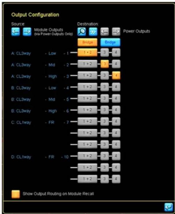
Figure 8-26: Bridge Mode (Lake-enabled amplifiers only)

When Bridge Mode is activated, CLASS 3 WIRING is required. Please refer to the Operation Manual for additional wiring information.
8.2.9 Latency Match
This button is available on all devices except MY8-LAKE. It is blue when disabled and orange when enabled.
This feature adds additional latency to the output signal to align latency with PLM Series devices. LATENCY MATCH is based on the following criteria:
- Input types for all devices are identical (Analog or AES only).
- Input sample rates for all devices are identical where AES inputs are being used.
- Outputs are set to analog.
For any other scenarios, the appropriate delay adjustments must be made manually.
8.2.10 Technical Data
The technical data screen is displayed by tapping TECHNICAL DATA (F5) on the I/O CONFIG button bar.
Technical Data includes hardware-based Frame data including IP Address, Dual Redundancy, Front Panel Configuration (D Series only) and Dante Slave Only settings that are unaffected by SYSTEM RECALL, FRAME REPLACE, FRAME PRESET RECALL or FRAME CONFIGURATION and SOFT RESET options. When any of these hardware-based parameters are changed, a power cycle is required to apply the changes.
Figure 8-27 shows the technical data screen for an LM 44 and a PLM 20K44. Most information is similar for all products, any product differences are detailed in the following sections. The LM Series and PLM Series have the same feature set available, and the D Series and PLM+ have a more advanced feature set available. All features are described in detail in the following sections:

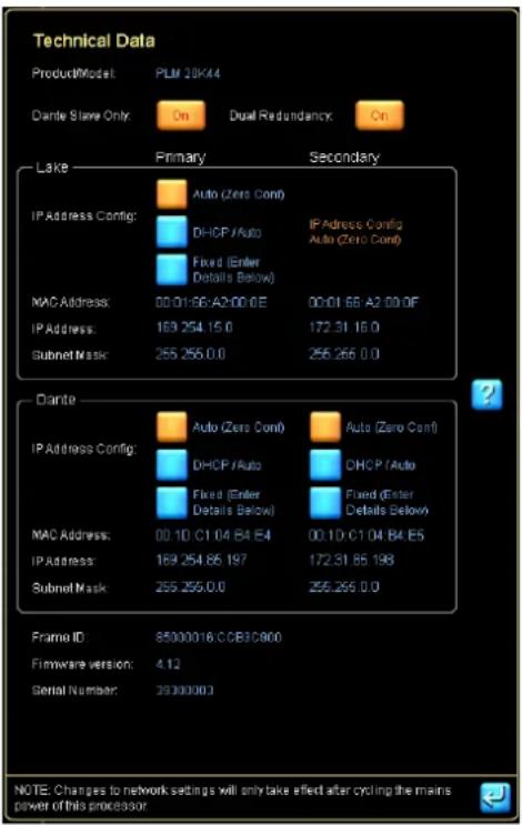
Figure 8-27: LM 44 and PLM+ 20K44 Technical Data Screens
8.2.10.1 Product/Model
The description and model number for the selected device.
8.2.10.2 Front Panel Enable (D Series only)
If Front Panel Enable is ON (orange), the front panel configuration functionality on the device will be active; this functionality will be disabled if this button is OFF (blue).

This hardware parameter is unaffected by SYSTEM RECALL, FRAME REPLACE, FRAME PRESET RECALL or FRAME CONFIGURATION and SOFT RESET options. It can be changed only via this screen and via a front panel Factory Reset.
8.2.10.3 Dante Slave Only (not applicable for MY8-LAKE)
If Dante Slave Only is Enabled, the device can only operate as a slave to the Dante network, and will not be part of the Dante Clock Master selection process. It is recommended that this setting is enabled for all devices unless the device is specifically required to be part of the Dante Clock Master selection process. This setting is enabled (ON) by default for Lake-enabled amplifiers and disabled (OFF) by default for LM Series devices. When running a Dante Dual Redundant system, it is recommended to have a few (2-6) Lake-enabled amplifiers with Dante Slave Only disabled.

This hardware parameter is unaffected by SYSTEM RECALL, FRAME REPLACE, FRAME PRESET RECALL or FRAME CONFIGURATION and SOFT RESET options. It can be changed only via this screen and via a front panel Factory Reset.
8.2.10.4 Dual Redundancy (not applicable for MY8-LAKE)
This option activates dual redundant network capabilities for Lake Controller data and Dante audio. For PLM and LM Series devices (and default for PLM+ and D Series), the secondary Ethernet port has an IP address in the 172.31.x.x range. For D Series and PLM+, the Secondary IP address for Dante can be configured manually. The power must be cycled on the Lake device to complete the change.
The Dual Redundancy option can also be viewed and changed for all devices (except MY8-LAKE) via the Global Control Tab.

This hardware parameter is unaffected by SYSTEM RECALL, FRAME REPLACE, FRAME PRESET RECALL or FRAME CONFIGURATION and SOFT RESET options.
This value can only be changed via the Technical Data screen, Global Control Tab, or via the Factory Reset option from the device front panel.
8.2.10.5 IP Address Config
This field is set by default to AUTO - ZERO CONF. It can also be set to AUTO - DHCP (if a DHCP server is used) or to a FIXED IP ADDRESS. If in DHCP mode without a DHCP server, the device will auto select an IP address just as in Auto Zero Conf. PLM+ and D Series devices have individual configuration for Lake and Dante. The power must be cycled on the Lake device to complete the change.

This hardware parameter is unaffected by SYSTEM RECALL, FRAME REPLACE, FRAME PRESET RECALL or FRAME CONFIGURATION and SOFT RESET options.
This parameter is changed only via this screen and via the FACTORY RESET option from the front panel of the device.
8.2.10.6 IP Address
The Internet protocol (IP) address identifies which device is sending or receiving information. The power must be cycled on the Lake device to complete the change. For PLM+ and D Series devices, there is a separate Dante module with its own IP address. When in AUTO or DHCP, it is possible to see the IP addresses currently used by the device. The Dante IP address specified is what can be seen in an online Dante Controller.
For the PLM+ and D Series, both the Lake and Dante IP addresses must be on the same subnet to enable Dante configuration via the Lake Controller, and to enable full firmware update of both components via the Lake Update Utility. If the IP Address of the Lake component is set to a fixed IP address, it is recommended that the Dante component is changed to the Lake address + 1.
If the FIXED IP ADDRESS option is selected as described in 8.2.10.5, this field becomes editable and an IP Address may be entered manually. When a device has Dual Redundancy enabled and the FIXED IP ADDRESS option is enabled, it is possible to manually enter the IP address for the secondary network as well. For the PLM and LM Series, the IP address of the secondary network is always in AUTO on the 172.31.x.x subnet.

This hardware parameter is unaffected by SYSTEM RECALL, FRAME REPLACE, FRAME PRESET RECALL or FRAME CONFIGURATION and SOFT RESET options.
This parameter is changed only via this screen and via the FACTORY RESET option from the front panel of the device.
The subnet mask is used for IP address routing; the default setting is 255.255.0.0 when AUTO - ZERO CONF is selected. The power must be cycled on the Lake device to complete the change.
If the FIXED IP ADDRESS option is selected as described in 8.2.10.5, this field becomes editable and a Subnet Mask may be entered manually.
This parameter is unaffected by SYSTEM RECALL, FRAME PRESET RECALL or soft FRAME RESET options. It is reset only via the FACTORY RESET option from the front panel of the device.
8.2.10.8 ID
The unique Lake device identifier.
8.2.10.9 Firmware
The firmware version that is currently running on the selected device.
8.2.10.10 Serial Number
Device as well as the front and rear panel display (not applicable for D Series and MY8-LAKE).
Displays the hardware serial number for the selected device. This is visible on the rear panel and in the front panel menu (not applicable for D Series and MY8-LAKE).
8.2.11 Input Router Mutes
Input Router Mutes represent the actual inputs to the device. Muting an input via Input Router Mutes will mute the signal to all Modules that are connected to that Input Router. To display the Input Router Mutes toolbar:
Tap INPUT ROUTER MUTES (F6) from the button bar on the I/O CONFIG screen
Tap the INPUT ROUTER MUTES zoom button from the Levels screen
The buttons describe the current status. An input with a red button labelled MUTED is currently muted and may be tapped to unmute the input. A button labelled UNMUTED is currently unmuted and may be tapped to mute the input.

Figure 8-28: Input Router Mutes

Input Router Mutes are not available when a device is offline.
8.2.12 Interactive Signal Path Block Diagram
The signal path of each Module is shown in graphical form on the right of the I/O CONFIG page. Each of the blocks can be selected to navigate directly to the associated EQ/LEVELS/XOVER/AUX/HPF/LPF screens.

After using the interactive block diagrams to access the other screens, the EQ/LEVELS EXIT button returns you to the I/O CONFIG page instead of HOME.
8.2.13 Input Selection (MY8-LAKE in Simplified View Only)
The MY8-LAKE device has a unique simplified view for the Mesa Frame configuration by default. In this view the input can be easily toggled between default Host output and AES input. Please refer to "8.2.7.2 Input Mixer" on page 144 and "22.4 I/O Configuration View Mode Options" on page 285 for further information.
8.2.14 Frame Config/Soft Reset
For Lake-enabled amplifiers this button reads SOFT RESET and resets the device to its factory default state, without removing any presets stored in the device, and without resetting the networking configuration data including IP Config, IP Address, Subnet Mask & Dual Redundancy settings.
For LM Series and MY8-LAKE devices, this button reads FRAME CONFIG and provides a sub-menu allowing the device to be configured as:
CONTOUR (2-Contour Modules for LM Series; 4-Contour Modules for MY8-LAKE) ▶ MESA EQ (4-Mesa EQ Modules for LM Series; 8-Mesa EQ Modules for MY8-LAKE) CONTOUR/MESA EQ (2-Contour Modules and 4-Mesa EQ Modules for MY8-LAKE)

For all products, configuring or resetting a device via the Lake Controller retains the current IP address setting and system/Frame presets.
8.3 Label & Lock
From the Modules menu, tap LABEL & LOCK to view a submenu with functions to label a Module or Frame and allow a system designer to lock Module and base configurations.
8.3.1 Module Label
The Module Label is a user-definable value at the bottom of the Module icon that identifies the Module.
To label a Module:
- Tap the desired Module icon on the MAIN page.
- Tap MODULE LABEL, enter a Module name, and tap OK.
8.3.1.1 Dynamic Module Label

Figure 8-29: Dynamic Module Label enabled
By default, the Module Label changes to the name of a Module file recalled. The Dynamic Module Label makes it possible to specify a Module Label, and configure it to have static parts of the name that are kept on a Module recall and not replaced with the name of the recalled module. With the Dynamic Module Label feature it is possible to specify a Suffix, or a Prefix and Suffix for the module label. To enable this feature, the pipe character is used (I) in the Module Label.
| Example with both Prefix and Suffix (two pipe characters used in the label): | |
| Module label displayed on work area before recall: Right 80deg Rack1:1 | |
| Starting module label: Right |80deg| Rack1:1 | |
| Name of Module file being recalled: 120deg | |
| Module label after recall: Right |120deg| Rack1:1 | |
| Module label displayed on work area after recall: Right 120deg Rack1:1 | |
| Example with only Suffix (one pipe characters used in the label): | |
| Module label displayed on work area before recall: 80deg Rack1:1 | |
| Starting module label: 80deg| Rack1:1 | |
| Name of Module file being recalled: 120deg | |
| Module label after recall: 120deg| Rack1:1 | |
| Module label displayed on work area after recall: 120deg Rack1:1 | |
Table 8-4: Example with both Prefix and Suffix (two pipe characters used in label)
Table 8-5: Example with only Suffix (one pipe character used in label)
On the work area module label, the pipe character itself is hidden. The on-screen displayed keyboard will highlight when the Dynamic Module Label is enabled, and it will:
▶ Display the persisted text in white ▶ Display the overwritten text in blue
When storing a Module file from a Module where Dynamic Module Label is used, the Store dialog will only suggest the part of the name that is part of neither Prefix nor Suffix.
Double pipe characters (||) will not control the Dynamic Module Label and are instead displayed as a single pipe character on work area.
If a system file stored in v6.8 or earlier contains module labels that contain pipe character in the name, these will be replaced with (i.e. converted to) double pipe characters in the label so that they are displayed as before and not treated as Dynamic Module Labels.
8.3.2 Frame Label
The Frame label is a ten-character user-defined value that appears on the Module icon and on the front panel of the device. The Frame label associates the Module icons with a Lake device.
To label a Frame:
- Tap any Module of the Frame you wish to label.
- Tap FRAME LABEL, enter a Frame name, and tap OK.

When a Frame consists of multiple Modules, labelling the Frame via one Module automatically updates the Frame label on any associated Module icons.
8.3.3 Module and Base Configuration Locking
The following functions are active only in Designer Mode:
▶ MODULE UNLOCKED/UNLOCK MODULE ▶ SET MOD PASSWORD ▶ BASE UNLOCKED/UNLOCK BASE ▶ SET BASE PASSWORD
For additional details on these functions, please refer to chapter 19.
8.4 Copy/Paste/Replace
From the MODULES menu, tap the COPY/PASTE/REPLACE button to view a submenu that allows the transferring of data between Modules. These functions enable fast setup of multiple speakers using the same type and configuration.
The REPLACE function allows assignment of a different physical hardware device to perform the task of a selected device (i.e., to transfer all data from one hardware device to another). The BATCH REPLACE function allows fast transfer of data from a virtual or offline configuration to online Frames.
8.4.1 Copy
This function is active only when a Module icon is selected. To copy data from a Module:
- Tap the Module icon that contains the data to copy.
- Tap COPY.
8.4.2 Paste
This function is active only when Module data has been previously copied and a destination Module icon is selected. To paste data to a Module:
- Tap the Module icon in which to paste the data.
- Tap PASTE.

A Mesa EQ Module cannot be pasted into a Contour Module and vice versa.
8.4.3 Replace Frame
The REPLACE function allows transfer of Module/Super Module/Group data between devices. If a previously used device is unavailable, or the device that performs a task is required to change, follow these steps:
- Tap COPY/PASTE/REPLACE from the Modules menu.
- Tap a Module from the Frame you wish to replace on the work area.
- Tap REPLACE FRAME
The Module scroll bar displays used and unused Modules.
- Tap a Module from an unused Frame, then tap COMPLETE REPLACE.
To locate a particular device, tap the SEL button on the front panel to center the unit on the scroll bar:
LM Series | Press the top-left dynamic function button on the front panel. PLM Series | Press the second dynamic function button down on the left on the front panel. PLM+ Series | Press the top-left dynamic function button on the front panel. D Series | Press the SELECT button to the far-right of the front panel.
8.4.3.1 Replace Frame Rules and Compatibility
All Modules of a Frame must be present on the Module scroll bar (i.e., no part of the Frame can be in use in the current system configuration). Network IP settings and Dual Redundancy configuration are not transferred during a Frame Replace operation; configure these manually on the destination Frame. PLM 10000Q and PLM 20000Q Frames may be replaced with PLM+ or D Series, and will populate Modules A&B only. Modules C&D will remain unaffected. PLM+ or D Series may be replaced with any product from either of these product lines without any loss of data. If a destination model cannot set a value contained in the source model, the appropriate minimum or maximum will be set and these discrepancies are indicated via the desired values and actual values within brackets [ ]. These products may not be replaced by a legacy PLM product.
PLM 14000 can only be replaced with an online PLM 14000.
For LM Series and MY8-LAKE devices, the source and destination Frames must be of the same configuration type (i.e., Contour, Mesa, or Contour/Mesa), and can only be replaced with a Frame of the same product type.
8.4.4 Complete Replace
This button completes the REPLACE FRAME function. This function is active only when the REPLACE button is selected and a destination Module has been selected from the Module scroll bar.
Data from the source Frame is transferred to the destination Frame, and the Frame from the scroll bar will now take the place of the source Frame in the system configuration.
If the source Frame is online, all Modules in the work area are returned to the scroll bar.

If a 2xContour module is replaced with a 4xContour module PLM+ or D Series, it is recommended to enable "Enable #Unused Page". This will move the unused module C&D to a new #Unused page. Any module(s) on this page will not be displayed on the ALL page.
8.4.5 Batch Replace
This button is active (blue) regardless of whether a Module is selected in the work area. When tapped, a screen similar to Figure 8-30 is displayed.
The left side of the screen displays offline or Virtual Frames present in the main work area. The right side of the screen displays available online Frames on the scrollbar.

To complete the BATCH REPLACE, all online destination Frames must be on the Module scroll bar, and not currently in use in the work area.

Please refer to section 8.4.3.1 for detailed information on Frame Replace rules and compatibility.
Frames are sorted by Frame type (product/configuration), then by Frame name. If the product type and Frame name match between an online and offline Frame, a number will automatically be assigned to the destination Frame.
Pressing the ME/SEL button on the front panel will identify the selected destination Frame with yellow highlighting.
Please refer to the notes in section 8.4.3 for rules relating to which products are compatible with each other for Batch Frame Replace.

If a 2xContour module is replaced with a 4xContour module PLM+ or D Series, it is recommended to enable "Enable #Unused Page". This will move the unused module C&D to a new #Unused page. Any module(s) on this page will not be displayed on the ALL page.
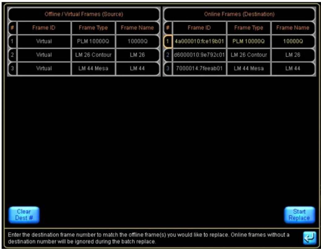
Figure 8-30: Batch Replace Screen
8.4.5.1 Assigning the Virtual Frames to the Destination Frames
With the exception of very small systems, the virtual/offline Frame must be labeled to enable Frame identification. If the destination Frame of the same product type and configuration is also labeled with a matching name, the assignment will be automatic. Tapping START REPLACE will transfer data to the associated online Frames.
If the destination Frames are not labeled:
- Type the corresponding offline/Virtual Frame number into the # field, either via the on-screen or a manual keyboard.
- The destination Frame will move up or down the list so that it is on the same row as its corresponding offline/Virtual Frame.
- Tap START REPLACE, then tap YES to the confirmation message.
All offline/Virtual Frame data will be transferred to the online Frames.
8.5 Remove
To remove a Module from the current system, tap the Module icon in the work area while in the MODULES menu, then tap REMOVE.
Audio will not be affected unless the Module is assigned to a Group that contains settings that affect the audio of the Module.

You can also remove a Module by dragging the Module icon to the Module scroll bar when in the MODULES menu.

No warning is displayed unless the selected Module is assigned to a Group. In this instance, removing a Module de-assigns it from all Groups to which it is currently assigned.
8.6 Module Store/Recall
Tap the MODULE STORE/RECALL button to view a submenu containing functions that recall and store Module and base configurations, and to store Frame presets. The button bar displays the following options and a scroll bar with files and folders.
![My Computer Default Modules Lake LoadLibrary 3.9 er Mode: Select an existing Module file or tap [New Store] to create new Module file Blank System C Home F1 Keep Group Assignment F2 Recall F3 Store F4 New Store F5 - F6 Base Configuration F7 Store/Recall EXIT F8 File Utilities F9 Frame Presets F10](/content/2026/07/1419186/images/f965a77bb01b506fca3ce88d00b8ad7e62830a4d25fee47421819bbd8e5647e1.jpg)
Figure 8-31: Module Store/Recall Menu and Scroll Bar
For detailed information on all of the Module file types supported by the Lake Controller, please refer to section 4.7.
8.6.1 Recall/Open
This button's function and label depends on whether a folder or file is selected. It is inactive when neither a file nor folder is selected, or when a Group icon is selected in the work area.
The button is labeled OPEN when a folder is selected. To open a folder, tap the desired folder icon on the scroll bar, then tap OPEN.

Double-tapping a folder or file icon also opens the folder or file.
The button is labeled RECALL when a file is selected. To recall a Module file, tap the desired file, then tap RECALL. Confirm the action by tapping YES to the warning message. By default, the Output Configuration
screen is displayed to enable confirmation of output routing - this setting can be changed by toggling the option on the Output Configuration screen.
By default, a Module recall will remove the Module from any assigned Groups and a warning will be displayed to confirm this action. If the Keep Group Assignment option is enabled, the assignment of the Module to the Group will be maintained during the Module recall.

Figure 8-32: Recalling a Module File

Recalling a Module file overwrites all data currently stored in the selected Module and if "Keep Group Assignment" is not enabled it will also remove the Module from any Groups.

EAV ® Greybox ™ file (.gyx) may also be recalled directly into the Modules of Lake-enabled amplifiers. Please refer to chapter 9 for further details.
8.6.2 Store
The STORE button stores over an existing file. This button is active only when a file is selected.
- Tap an existing file to store over (overwrite).
- Tap STORE.
- Confirm the action by tapping the YES button in the warning message.

If the selected file is set to READ ONLY, the STORE function is gray (inactive).
8.6.3 New Store
The NEW STORE button stores the current Module configuration under a new file name.
- Navigate the file system, and tap the desired destination folder to select it.
- Tap NEW STORE.
- Enter the file name.
- Tap OK.
The scroll bar displays the new file.
8.6.4 Base Configuration
A base configuration file defines a starting point for the Module setup. It contains EQ and levels settings, invisible to the user, which represent the appropriate general configuration for a particular speaker type.
EQ, LEVELS and XOVER settings for an existing Module may be stored as a base configuration for future use when configuring new Modules. A system designer can also lock access to the XOVER/AUX screens (Contour) or HPF/LPF screen (Mesa EQ) within the base configuration file. For details on this function, please refer to chapter 19.
The RECALL/OPEN, STORE, and NEW STORE functions operate identically as described above, but the available files/folders in the scroll bar change when BASE CONFIGURATION is selected.
To store or recall a base configuration file, perform the following steps:
- Select a Module icon in the work area.
- Tap MODULE STORE/RECALL from the MODULES menu.
- Tap BASE CONFIGURATION.
- Navigate to the desired folder/file.
- Use the RECALL/STORE/NEW STORE functions as required.

A base configuration file cannot be created from a Virtual Frame.
8.6.5 File Utilities
This button provides a submenu containing further functions that manage files and folders from within the Lake Controller.
8.6.5.1 Open
This button is active only when a folder is selected. Tap OPEN to open the selected folder.
8.6.5.2 Read Only
This function protects important files from being accidentally overwritten or deleted and is active only when a file is selected. The currently selected file's status is identified by the color of the READ ONLY button:
▶ ORANGE - indicates the selected file is set to READ ONLY. BLUE - indicates the selected file is not protected.
To change the Read Only status of a file:
- Tap a file from the scroll bar to select it.
- Tap READ ONLY to toggle function ON (orange) and OFF (blue).
8.6.5.3 Rename
This button allows the name of a file/folder to be changed.
- Tap the required file/folder from the scroll bar, then tap RENAME.
- Enter the new name, and tap OK.
8.6.5.4 Delete
This button is active only when a file or folder is selected. When a file is selected, this function will only be available if the file is not set to READ ONLY. To delete a file or folder:
- Tap a file or folder to select it, then tap DELETE.
- Confirm action by tapping YES in the warning message.

Deletion of a file is permanent and cannot be restored using the UNDO function.
8.6.5.5 New Folder
This button creates a new folder in the current directory.
- Navigate to the desired directory location and tap NEW FOLDER.
- Enter the folder name, and tap OK.
8.6.6 Frame Presets
A Frame preset is a configuration for the device stored locally inside the device for fast retrieval from the Front Panel (not applicable for D Series or MY8-LAKE), Lake Controller or Preset Manager.
There are 100 preset locations available for all Lake-enabled devices, except MY8-LAKE; the MY8-LAKE card does not support Frame Presets as the host controls all snapshot/preset functionality.
Frame presets can be recalled instantly using the front panel, without the use of the Lake Controller software. For further information on presets and Preset Manager functionality, please refer to chapter 28.
The FRAME PRESETS button provides a submenu containing the functions described below.
8.6.6.1 Store
This button is active only when a Module of an online Frame is selected and a preset location is selected that is not empty (such as when overwriting an existing preset).
To overwrite the settings of the Frame preset:
- Recall or configure both Modules of the Frame with the required settings.
- Tap a Module icon of the Frame containing the data you wish to store.
- Tap FRAME PRESETS from the MODULE STORE/RECALL menu.
- Select a previously used preset location, and tap STORE.
8.6.6.2 Store with New Name
This button is active only when a Module of an online Frame is selected and a preset location is selected. The function is similar to STORE, but always provides the on-screen keyboard for entering a preset name.
8.6.6.3 Clear
This button is active only when a Module of an online Frame is selected and a preset location containing data is selected. To delete the data in a preset location, perform the following steps:
- Select the preset location from the scroll bar.
- Tap CLEAR, then YES to the warning message.
- Tap a Module icon of the Frame containing the preset for deletion.
8.7 Add Page
The ADD PAGE function is always available from the MODULES menu and creates additional pages that help manage large systems that contain many Module and Group icons.
8.8 Super Modules (LM & PLM Series only)
Super Modules enable the user to control Contour Modules that span multiple Frames (not applicable for PLM+, D Series or MY8-LAKE) as a single entity in the user interface. A Super Module can be a combination of two or more processing Modules on the same or different Frames that act together to provide the same audio processing with flexible output routing.
8.8.1 Assigning Super Modules
- Tap MODULES.
- Tap a Module on the scroll bar, and place it in the work area.
- Tap SUPER MODULES from the MODULES menu. A Venn icon that represents the combination of multiple Modules appears in the scrolling bar as shown in Figure 8-33.
- Tap this Super Module icon and place it in the work area. The icon displays as a Super Module marked as empty.
- Tap the empty Super Module to select it, then tap ASSIGN MODULE. A message displays, advising Group assignments of the first Module assigned to a Super Module will be transferred to subsequently assigned Modules.
- Tap the icons for Modules to be included in the Super Module. The Modules are assigned to the Super Module and removed from the work area. The Modules contained in the Super Module appear in the scrolling bar when the Super Module is selected.

Figure 8-33: Super Modules
8.8.2 Super Module EQ/Levels or Module EQ/Levels
These functions enable you to view or change the EQ levels of a Module or Super Module. When a Module is selected, you change only the EQ and level of that Module. When a Super Module is selected, you change the EQ and level for all Modules contained in that Super Module. See chapter 6 for more information on EQ/Levels.
To view the EQ/Levels of a Module or Super Module, tap the Module or Super Module to select it, then tap SUPER MOD EQ/LEVELS or MODULE EQ/LEVELS.
8.8.3 SM Routing: I/O Config
This button reads I/O CONFIG when a Module is selected and SM ROUTING when a Super Module is selected. For further information on the I/O CONFIG option, please refer to section 8.2.
The SM ROUTING function displays the Super Module output routing pop-up window. It shows each of the elemental Modules contained in the Super Module and its available output routing options.
To configure routing for a Super Module:
- From HOME, tap MODULES.
- Select a Super Module in the work area.
- Tap SM ROUTING.
Figure 8-34 shows the SM ROUTING screen for a stereo Classic 4-Way configuration split across two Lab.gruppen PLM 10000Q amplifiers. The sub and low channels are being driven by one amplifier in Bridged Mode, and the mid and high channels by a separate amplifier in normal mode.![graph TD A["Input Gain"] --> B["Input EQ"] B --> C["Input Delay"] C --> D["Output EQ XVR"] D --> E["Output Levels"] C --> F["Output EQ XVR"] F --> G["Output Levels"] C --> H["Output EQ XVR"] H --> I["Output Levels"] D --> J["1 + 2"] E --> K["3 + 4"] F --> L["1 + 2"] G --> M["3 + 4"] H --> N["1 + 2"]…](/content/2026/07/1419186/images/063299dc339c034099d1c26fb785db63b8ddd489f206d64a00c69a0a0b168b51.jpg)
Figure 8-34: SM Routing Screen
With this Super Module configuration, two 4-Way speakers can be controlled simultaneously via one Super Module icon, with all changes to levels, EQ and crossover being duplicated in real time across both amplifiers.
The DESTINATION arrow icons enable selection of available output types. The magnifying glass icon navigates to the I/O CONFIG screen of the associated Frame. Please refer to section 8.2 for further details.
The SM Routing screen is divided into two sections. The left side contains the interactive block diagram that provides access to Super Module settings; the right side displays output configuration information for each Module.
8.8.4 Label Frame
To label a Frame, perform the following steps:
- Select a Module in the work area, or from the Super Module scroll bar if all Modules of the Frame are already assigned to a Super Module.
- Tap LABEL FRAME
8.8.5 De-assigning a Super Module
To de-assign a Super Module:
- Select a Super Module in the work area and tap DE-ASSIGN MODULE [F7]
- Tap the Module icons on the scroll bar to remove them from the Super Module
8.8.6 Remove Super Module
To remove a Super Module:
- Tap the Super Module icon in the work area and tap REMOVE SUPER MOD. A message appears, advising that removing the Super Module disassociates it with all the Modules currently assigned to it.
- Tap YES to proceed. The Super Module disappears.

A Super Module can also be removed by dragging it to the Super Module scroll bar.
9. Module File Types & Lake LoadLibrary™
Lake devices provide two categories of Modules; Contour Modules and Mesa Modules. Contour Modules are suitable for devices that can perform loudspeaker crossover functionality, and Mesa Modules are suitable for devices that provide equalization only.
This chapter provides a detailed reference for all Lake Module file types. Default Module files are located in the Default Modules folder and can be accessed and recalled utilizing the MODULE STORE/RECALL menu.
9.1 Module Types Overview
Within the Contour Module category, there are five distinct types of Module:
- Classic Crossover Modules (featuring Bessel, Butterworth, and Linkwitz-Riley crossovers, available with roll-off ranging from 6 dB/octave to 48 dB/octave).
- Auxiliary Output Modules (provides EQ only functionality with a single input mix to multiple outputs when in Contour Mode).
- Linear Phase Crossover Modules (providing zero phase distortion with steep transition slopes using FIR filters).
- FIR Modules (combination of FIR filters, Classic crossovers, and output-specific driver EQ) - only available on Lake-enabled amplifiers by recalling an FIR Module, or via the import of EAW® Greybox™ files (.gyx), providing support for EAW Focusing.
- XP Modules (can be used for both Auxiliary and Crossover use, combining FIR filters and classic Bessel, Butterworth and Linkwitz-Riley LPF/HPF available with roll-off ranging from 6 dB/octave to 48 dB/octave and output-specific driver EQ, Multiband Limiter, Pre-Output EQ with ALL-pass filters. Also offers Array-optimization capability and integration). To create advanced Speaker Presets, there is also a custom control interface available for additional configuration. Contact Lab.gruppen support for more information.
The MESA EQ Module category provides a signal Module type of MESA EQ, that it defaulted for use as a single input to single output, full bandwidth EQ Module and also provides HPF/LPF functionality.
9.2 Supplementary Module Data
Any Module file may contain additional parameters relating to the power output stage, including Amplifier Gain and ISVPL™ limiter. These parameters are used when the file is loaded into a Lake-enabled amplifier and ignored when loaded into another Lake device; these parameters are retained and passed through to new Module files via the Module/System Store commands.
Additionally, loudspeaker electrical characteristic parameters (termed Fingerprint and used for LoadSmart™ verification) are stored and recalled via a supplementary “.mdl” file with the same filename. This Fingerprint file must be present in the same directory as the Module file; it is stored and recalled for Lake-enabled amplifiers, and ignored for other Lake devices. Fingerprint data may be reconnected with a Module file simply by renaming or moving the mdl file to ensure it has the same filename and directory location as its associated Module file. When a Fingerprint is loaded, this can be seen in the LoadSmart tab of the Amplifier Events & Control view.
9.3 Module Type Abbreviations
Figure 9-1 identifies the Module type abbreviation code.

Figure 9-1: Module Icon indicating Module Type Code
Table 9-1 describes the various abbreviation codes along with the associated Module description.
| Abbr. Description # Modules used | ||
| 1 Classic 1-Way or 1-Auxiliary Outputs 1 | ||
| 2 Classic 2-Way or 2-Auxiliary Outputs 1 | ||
| 2+1 Classic 2-Way + 1-Auxiliary Outputs 1 | ||
| 3 Classic 3-Way or 3-Auxiliary Outputs 1 | ||
| 3+1 Classic 3-Way + 1-Auxiliary Outputs 1+1 borrowed channel | ||
| 4 | Classic 4-Way or 4-Auxiliary Outputs | 1+1 borrowed channel |
| 5 | Classic 5-Way or 5-Auxiliary Outputs | 1+2 borrowed channel |
| 6 Classic 6-Way or 6-Auxiliary Outputs 2 | ||
| LP2 | Linear Phase 2-Way + 1-Auxiliary Outputs | 1 |
| LP3 | Linear Phase 3-Way | 1 |
| LP4 | Linear Phase Brick Wall 4-Way | 2 |
| FIR1 | FIR 1-Way 2 | |
| FIR2 FIR 2-Way 2 | ||
| FIR3 | FIR 3-Way | 2 |
| XP1 | XP1-Way | 1 |
| XP2 | XP2-Way | 2 |
| XP3 | XP3-Way | 3 |
| XP4 | XP4-Way | 4 |
| MEq Mesa EQ 1 | ||
Table 9-1: Module Type Abbreviations

The Mesa EQ Module can only be used on LM Series and MY8-LAKE devices.

The FIR Modules can only be used on Lake-enabled amplifiers.

The XP Module can only be used on PLM+ and D Series amplifiers.
9.4 Classic Crossovers/Auxiliary Outputs
This section describes the available combinations of classic crossovers and shows the default signal path for each configuration.
Classic 2- or 3-Way Modules, or any Module requiring less than three channels, may be used in any combination on a Lake device. Linear Phase 2-Way and 3-Way Modules may also be recalled in any combination alongside classic crossover Modules.
Classic 4-, 5-, and 6-Way Modules, as well as Modules requiring more than three channels, are provided as fixed configuration options. A Module with more than three channels may only be recalled into Module A or C and, in most cases, the remaining outputs of the device can be configured to provide other crossovers and auxiliary outputs.
9.4.1 Classic 2-Way + 1-Auxiliary Outputs
The CL2w+1a Module provides an auxiliary output that can be driven by the post-input EQ signal, post-input EQ and delay, or from an independent input mix. By default, the auxiliary output is driven by the post-input EQ signal.
If you switch the auxiliary channel to receive input from its own input mixer, the auxiliary channel will no longer be muted by the Module input mute control. The auxiliary channel can be muted by the channel's output mute control.
![graph TD A["Input 1: 0.00"] --> B["Input Gain"] C["Input 2: Input 4"] --> B B --> D["Input EQ"] D --> E["Input Delay"] E --> F["Output EQ/Xvr"] E --> G["Output Levels"] H["Input 1: 0.00"] --> I["Input 3"] J["Input 2: Input 4"] --> I I --> K["Post EQ"] K --> L["Output EQ/Xvr"] K --> M["Output Levels"…](/content/2026/07/1419186/images/45ec4f02c92e4a3aad80c56a9806877ace63133677b77d954c860ae405528399.jpg)
Figure 9-2: Classic 2-Way+1-Auxiliary Outputs
To change the auxiliary output to receive its own independent input mix, tap the switch selector box labeled POST EQ.
9.4.2 Classic 3-Way and 3-Auxiliary Outputs
The signal paths for both of these Module types look similar, but the Classic 3-Way (shown in Module A) has a single crossover page providing specific frequency bands from each output.
The 3-Auxiliary Outputs Module provides three full-bandwidth channels per Module. Each of these outputs can be configured independently as required using traditional high-pass and low-pass filters, which are available on each independent Auxiliary Output page.
![graph TD A["CL3Way"] --> B["Input 1: 0.00"] A --> C["Input 2: Input 4"] B --> D["Input Gain"] C --> E["Input Gain"] D --> F["Input EQ"] E --> G["Input EQ"] F --> H["Input Delay"] G --> I["Input Delay"] H --> J["Output EQ/Xvr"] H --> K["Output Levels"] I --> L["Output EQ/Xvr"] I --> M["Output Levels"…](/content/2026/07/1419186/images/83caeef376f0c5e648e6d623256e267cc2a29d35b5152cb1967084fcf94fa974.jpg)
Figure 9-3: Classic 3-Way and 3-Auxiliary Outputs

The Classic 2-Way, Classic/Linear Phase 2-Way + 1-Auxiliary Outputs, Classic/Linear Phase 3-Way, and Classic 3-Auxiliary Outputs Modules can be used in any combination on all available Modules.
9.4.3 Classic 3-Way + 1-Auxiliary Outputs (with Classic 2-Way/2-Aux)
The Classic 3-Way + 1-Auxiliary Output (CL3w+1a) Module allows the remaining two output channels to be configured as either Classic 2-Way or 2-Auxiliary Outputs.
Separate input EQ (PEQ/BLEQ/GEO) is available for the CL3w+1a and the 2-Way/2-Aux Modules.
As with the Classic 2-Way + 1-Auxiliary Outputs Modules, the Auxiliary channel on the CL3w+1a can be fed post-input EQ, post-input EQ and delay, or from its own independent Input Mixer.
![graph TD A["Input 1: DEMO 3+1 CL3w+1a"] --> B["Input 0.00"] A --> C["Input 2: DEMO 3+1 CL3w+1a"] B --> D["Input Gain"] C --> E["Input Gain"] D --> F["Input EQ"] E --> G["Input EQ"] F --> H["Post Delay"] G --> H H --> I["Output EQ/Xvr"] H --> J["Output Levels"] H --> K["Output EQ/Xvr"] H --> L["Outpu…](/content/2026/07/1419186/images/d7755b2dadfcc341674a9b36b068acac4a8d5d9f2fe8e133e5a31fa74b48895d.jpg)
Figure 9-4: Classic 3-Way+1-Aux with Classic 2-Way
9.4.4 Classic 4-Way/4-Aux (with Classic 2-Way/2-Aux)
The Classic 4-Way (CL4way) or 4-Auxiliary Outputs (4aux) Modules allow the remaining two output channels to be configured as either Classic 2-Way or 2-Auxiliary Outputs.
Separate input EQ (PEQ/BLEQ/GEO) is available for the Classic 4-Way/4-Aux and the 2-Way/2-Aux Modules
![graph LR A["Input 1: 0.00"] --> B["Input Gain"] C["Input 2: Input 4"] --> B B --> D["Input EQ"] D --> E["Input Delay"] F["Output EQ/Xvr"] --> G["Output Levels"] H["Output EQ/Xvr"] --> I["Output Levels"] J["Output EQ/Xvr"] --> K["Output Levels"] L["Output EQ/Xvr"] --> M["Output Levels"]](/content/2026/07/1419186/images/3ec5de4fff19fe6ad69bc846944d1f22932870429ed639b8bdac2477cec00bf6.jpg)
![graph TD A["Input 1"] --> B["Input Gain"] C["Input 2"] --> B D["Input 3"] --> B E["Input 4"] --> B B --> F["Input EQ"] F --> G["Input Delay"] G --> H["Output EQ/Xvr"] G --> I["Output Levels"] G --> J["Output EQ/Xvr"] H --> K["Output Levels"] I --> L["Output Levels"]](/content/2026/07/1419186/images/d1759d1fa8fd22e9517e5255a78a33e09ef4ecb4d2efa673d2fccaf8de1cea56.jpg)
Figure 9-5: Classic 4-Way with Classic 2-Way
9.4.5 Classic 5-Way/5-Aux (with 1-Auxiliary Outputs)
The Classic 5-Way (CL5way) or 5-Auxiliary Outputs (5aux) Module provides an auxiliary channel on output 6.
Separate input EQ (PEQ/BLEQ/GEQ) is available for the Classic 5-Way/5-Aux and the 1-Auxiliary (1aux) Output Modules
![graph TD A["DEMO 5 CL5way"] --> B["Input 1: 0.00"] A --> C["Input 2: Input 3"] A --> D["Input 4: Input 4"] B --> E["Input Gain"] C --> E D --> E E --> F["Input EQ"] F --> G["Input Delay"] G --> H["Output EQ/Xvr"] G --> I["Output Levels"] H --> J["Output Level 1"] I --> K["Output Level 2"] J --> L["O…](/content/2026/07/1419186/images/1ebdb49245d31f4ef1e9741bb744387cb5ff99a6eda8013254dfc1114da14b86.jpg)
![graph LR A["B DEMO 1\n1Aux"] --> B["Input 1"] A --> C["Input 2"] A --> D["Input 3"] B --> E["0.00"] C --> F["Input 4"] D --> G["Input Gain"] G --> H["Input EQ"] H --> I["Input Delay"] I --> J["Output EQ/Xvr"] J --> K["Output Levels"] K --> L["Search Icon"]](/content/2026/07/1419186/images/ee68067a333ce0e17ecf6047c52883da6722a593e2359b397a3117835bee1288.jpg)
Figure 9-6: Classic 5-Way with 1-Auxiliary Outputs
9.4.6 Classic 6-Way/6-Auxiliary Outputs
The Classic 6-Way (CL6way) or 6-Auxiliary Outputs (6aux) Modules use a single Module input mix with the output split to all six output channels.
![graph LR A["A/B DEMO 6 CL6way"] --> B["Input 1: 0.00"] A --> C["Input 2: Input 4"] B --> D["Input Gain"] C --> D D --> E["Input EQ"] E --> F["Input Delay"] F --> G["Output EQ/Xvr"] F --> H["Output Levels"] G --> I["Output EQ/Xvr"] H --> J["Output Levels"]](/content/2026/07/1419186/images/b66f89555b501ba2b5f7cda26ccc7dc7769eae7016de0cd330deac528a405669.jpg)
Figure 9-7: Classic 6-Way
9.5 Linear Phase Crossovers
Linear phase modules utilize FIR filters to create steep transition slopes to divide the frequency bands. The phase response of all channels summed together is flat and therefore all frequencies are equally delayed which results in no phase distortion. Linear phase crossovers are available as 2-, 3-, and 4-Way Module types.
9.5.1 Linear Phase 2-Way (+1-Auxiliary Outputs)
The Linear Phase 2-Way (LP2way) provides an auxiliary channel with traditional HPF/LPF for each Module (LP2w+1a). The Auxiliary channel can be fed post-input EQ, post-input EQ and delay, or from an independent Input Mixer.
![graph TD A["Input 1"] --> B["0.00"] C["Input 2"] --> D["Input 4"] E["Input 3"] --> F["Input Gain"] G["Input 4"] --> H["Input EQ"] I["Input 1"] --> J["0.00"] K["Input 2"] --> L["Input 4"] M["Input 3"] --> N["Post EQ"] O["Input 4"] --> N N --> P["Output EQ/Xvr"] N --> Q["Output Levels"] N --> R["Outpu…](/content/2026/07/1419186/images/143ec225fca10df8635513433f0c34bf8ddcefef943e30a713a8861fca39c392.jpg)
Figure 9-8: Linear Phase 2-Way + 1-Auxiliary Outputs
9.5.2 Linear Phase 3-Way
The Linear Phase 3-Way (LP3way) has a similar signal path to the Classic 3-Way (CL3way).
![graph TD A["DEMO LP3\nLP3way"] --> B["Input 1\n0.00"] A --> C["Input 2\nInput 4"] B --> D["Input Gain"] C --> D D --> E["Input EQ"] E --> F["Input Delay"] F --> G["Output EQ/Xvr"] F --> H["Output Levels"] F --> I["Output EQ/Xvr"] G --> J["Output Levels"] H --> K["Output Levels"] I --> L["Output Leve…](/content/2026/07/1419186/images/9521527500753323844d81e2e82eebcef6baf86d3b630439213579160bb89ee2.jpg)
Figure 9-9: Linear Phase 3-Way
9.5.3 Linear Phase 2-/3-Way EQ/MaxPeak combinations
The LP2 and LP3way Modules use a significant amount of processing power to create steep crossovers with flat phase response. For this reason, the full amount of output-specific EQ filters can only be used if the MaxPeak is disabled on the Module, as the MaxPeak Limiter also requires a large amount of processing.
The MaxPeak Limiter process is disabled when the total MaxPeak level (including Group and factory settings) is 25 dBu or greater. The following crossover EQ filters for the LP2 and LP3way are available:
▶MaxPeak Activated: 10 EQ Filters + High-pass Filter
MaxPeak Deactivated: 15 EQ Filters + High-pass Filter
9.5.4 Linear Phase Brick Wall 4-Way
The Linear Phase Brick Wall 4-Way (LP4way) uses the processing power of two Modules to create extra-steep crossovers.
![graph TD A["A/B DEMO LP4\nLP4neg"] --> B["Input 1\n0.00"] A --> C["Input 2\nInput 3"] A --> D["Input 4\nInput 4"] B --> E["Input Gain"] C --> E D --> E E --> F["Input EQ"] F --> G["Input Delay"] G --> H["Output EQ/Xyr\nOutput Levels"] G --> I["Output EQ/Xyr\nOutput Levels"] G --> J["Output EQ/Xyr\nO…](/content/2026/07/1419186/images/48a7dd37163800c719b183488ac4b05151c58f8139b3b90e6f6d492c50b4a1cb.jpg)
Figure 9-10: Linear Phase Brick Wall 4-Way
9.6 FIR Module
This module incorporates a combination of FIR (finite impulse response) and IIR (infinite impulse response) technology. The extensive FIR filters can be used to create both crossovers and driver EQ. The phase can be absolutely controlled rendering linear phase, minimum phase, or arbitrary phase filters. The IIR filters can be used to create classic crossovers and specific driver EQ.
There are some SpeakerPresets in the Lake LoadLibrary that use the FIR module.
FIR modules supports EAW Focusing through direct import of EAW greybox files into the Lake Controller. The latest EAW greybox files can be downloaded via: http://www.eaw.com/downloads/

The FIR module cannot be created or configured via the Lake Controller. A third party software plugin is available for the Lake Controller; please contact Lake support if you are a loud-speaker manufacturer and would like further information.
9.6.1 FIR 1-Way
The FIR 1-Way (FIR1) is a FIR/IIR processing program that uses the processing power of two Modules. This program is activated by recalling an FIR Module or by recalling an EAW Greybox (.gyx) file.
![graph LR A["Virtual PLM 10000Q\nA/B\n10000Q\nFIRI\nJF10 SNGL"] --> B["Input 1\n0.00"] B --> C["Input Gain"] C --> D["Input EQ"] D --> E["Input Delay"] E --> F["Output EQ/Xvr"] F --> G["Output Levels"] G --> H["Search"] I["Input 2"] --> B](/content/2026/07/1419186/images/f5a333fc6a1d0088b5c8e0236775659cc248383f6d7329c9abf733f4d62413c4.jpg)
Figure 9-11: FIR 1-Way
9.6.2 FIR 2-Way
The FIR 2-Way (FIR2) is a FIR/IIR processing program that uses the processing power of two Modules. This program is activated by recalling an FIR Module or by recalling an EAW Greybox (.gyx) file.
![graph LR A["Virtual PLM 10000Q A/B 10000Q FIR2 MV12 BI"] --> B["Input 1: 0.00"] A --> C["Input 2:"] B --> D["Input Gain"] C --> D D --> E["Input EQ"] E --> F["Input Delay"] F --> G["Output EQ/Xvr"] F --> H["Output EQ/Xvr"] G --> I["Output Levels"] H --> J["Output Levels"]](/content/2026/07/1419186/images/51825b2dd9da6d52c5a5d3f645589e56372354acc7efaf014a6770de7bb8ed96.jpg)
Figure 9-12: FIR 2-Way
9.6.3 FIR 3-Way
The FIR 3-Way (FIR3) is a FIR/IIR processing program that uses the processing power of two Modules. This program is activated by recalling an FIR Module or by recalling an EAW Greybox (.gyx) file.
![graph LR A["Virtual PLM 10000Q A/B 10000Q FIR3 KF740x10 TRI"] --> B["Input 1 0.00"] A --> C["Input 2"] B --> D["Input Gain"] C --> D D --> E["Input EQ"] E --> F["Input Delay"] F --> G["Output EQ/Xvr"] F --> H["Output Levels"] F --> I["Output EQ/Xvr"] F --> J["Output Levels"]](/content/2026/07/1419186/images/7f822e3eab0c7ad7d51b992fbcb6b5d6da4efbca1ab077b0e83c421f3a7c1188.jpg)
Figure 9-13: FIR 3-Way
9.7 XP Module [PLM+ and D Series only]
Lake-enabled amplifiers (PLM+ and D Series) support the XP Module type, which incorporates a combination of FIR and IIR technology. The extensive FIR filters can be used to create both crossovers and driver EQ. The phase can be absolutely controlled, rendering linear phase, minimum phase, or arbitrary phase filters. The IIR filters can be used to create classic crossovers and specific driver EQ. The module also includes a pre-output EQ which are IIR filters (includes ALL-pass) which are separated from the XOVER view.
The XP Module also includes an optional Multiband Limiter on each of the outputs.

Figure 9-14: Array Optimizer EQ view
The XP Module is prepared for Array Optimization capabilities using both FIR and IIR. If there are Array Optimization settings sent to the module, this can be viewed from the "Array Opt" button in the XP signal flow.
Any Array Optimization data is stored in a System file, but storing a module where Array Optimization is enabled will not store the Array Optimization data.
There is also an option to configure a latency when bypassed. This creates a consistent latency in the system with and without Array Optimization. The Latency when bypassed setting is stored in the Module file.
It is also possible to disable the Array Optimization capability for the XP module. When configured for "Not capable", the module will not be available in the optimizer software and in the statistics view it will be displayed in the "Not capable" section.
![Lab Gruppen PLM 5K44 - XP Module [PLM+ and D Series only] - 2](/content/2026/07/1419186/images/63144dc3fea95cdb2b8ff21b12e6f0cdf4ffe572746822bf44324a5274dd90a0.jpg)
The XP module does have a lot more features which cannot be controlled or configured via the Lake Controller. A plugin API is available for the Lake Controller which offers control and configuration for everything. Please contact Lake support if you are a loudspeaker manufacturer and would like more information and the complete SDK.
9.7.1 XP 1-Way
The XP 1-Way (XP1) is a FIR/IIR processing program with Multiband Limiter and Array Optimization that uses the processing power of one Contour Modules.
![graph LR A["XPI"] --> B["Input 1: 0.00"] A --> C["Input 2: Input 4"] A --> D["Input Gain: Input EQ"] D --> E["Input Delay: Input EQ"] E --> F["Pre-Out EQ"] F --> G["Output EQ/Xvr"] G --> H["Array Opt"] H --> I["Output Levels"] I --> J["Search icon"]](/content/2026/07/1419186/images/6aabc7c308edd7d08cfb2640d24d08523662b36e2349187b1eec2f8884343520.jpg)
Figure 9-15: XP-1way
9.7.2 XP 2-Way
The XP 2-Way (XP2) is a FIR/IIR processing program with Multiband Limiter and Array Optimization that uses the processing power of two Contour Modules. This can only be recalled to Module A or C.
![graph LR A["A/B Demo XP2 XP2wag"] --> B["Input 1 0.00"] A --> C["Input 2"] A --> D["Input 3"] B --> E["Input Gain"] C --> E D --> E E --> F["Input EQ"] F --> G["Input Delay"] G --> H["Pre-Out EQ"] H --> I["Output EQ/Xvr"] H --> J["Output EQ/Xvr"] I --> K["Array Opt"] J --> L["Array Opt"] K --> M["Ou…](/content/2026/07/1419186/images/8bebf998927ffddcfd3d3c2318671c2d3e92e653c1bab50ea3678b2566a311e3.jpg)
Figure 9-16: XP-2way
9.7.3 XP 3-Way
The XP 3-Way (XP3) is a FIR/IIR processing program with Multiband Limiter and Array Optimization that uses the processing power of three Contour Modules. This can only be recalled to Module A.
![graph LR A["A/B/C Demo XP3 XP3way"] --> B["Input 1 0.00"] B --> C["Input Gain"] C --> D["Input EQ"] D --> E["Input Delay"] E --> F["Pre-Out EQ"] F --> G["Output EQ/Xvr"] G --> H["Array Opt"] H --> I["Output Levels"] F --> J["Output EQ/Xvr"] J --> K["Array Opt"] K --> L["Output Levels"] F --> M["Outp…](/content/2026/07/1419186/images/63820717b138ca46df0b10e416fd8dfa837a0e3d63e3169f5587aeb78368a81a.jpg)
Figure 9-17: XP-3way
9.7.4 XP 4-Way
The XP 4-Way (XP4) is a FIR/IIR processing program with Multiband Limiter and Array Optimization that uses the processing power of four Contour Modules. This can only be recalled to Module A.
![graph LR A["ABCD Demo XP4 XP4way"] --> B["Input 1 0.00"] A --> C["Input 2"] A --> D["Input 3"] A --> E["Input 4"] B --> F["Input Gain"] C --> F D --> F E --> F F --> G["Input EQ"] G --> H["Input Delay"] H --> I["Pre-Out EQ"] I --> J["Output EQ/Xvr"] J --> K["Array Opt"] K --> L["Output Levels"] I --…](/content/2026/07/1419186/images/8a5e65edc47e84fd06fb8701ab08864386570bb8ce4f719708820b51df8afa9d.jpg)
Figure 9-18: XP-4way
9.8 Mesa EQ Module
The Mesa EQ Module type is abbreviated as MEq on the Module icon. The Mesa EQ provides EQ only (with HPF/LPF) functionality.
![graph LR A["Input 1"] --> B["0.00"] C["Input 2"] --> D["Input 4"] E["Input 3"] --> F["Input 5"] G["Input 4"] --> H["Input 6"] I["Input 5"] --> J["Input 7"] K["Input 6"] --> L["Input 8"] M["Input Gain"] --> N["Input EQ"] N --> O["Input Delay"] O --> P["HPF/LPF"] P --> Q["Output Levels"] R["DEMO MEq M…](/content/2026/07/1419186/images/ca920dd4d9b3b26b5adccd4f1d8d424799ebddc175c3e412cac316b55a7d7ad4.jpg)
Figure 9-19: Mesa EQ
9.9 Lake LoadLibrary
The Lake LoadLibrary is a collection of over 1000 speaker presets distributed with the Lake Controller installer and available as a stand-alone download from the Lake website.
Lake LoadLibrary speaker presets can include individual or sets of Contour or Mesa Module files providing fast and accurate tuning of a wide range of PA systems. These files can also include additional parameters specific to certain devices either within the Module file itself, or via a supplementary .mdl file as explained in section 9.2.
The Lake LoadLibrary can include:
- Presets designed by the loudspeaker manufacturer
- Presets designed by Lab.gruppen
- Presets designed by the Lake community (end-users)
9.10 Additional Information
For additional information on Lake LoadLibrary speaker presets, please refer to the LoadLibrary release notes included in the Lake Controller software installation package.
Please refer to section 20.3 on page 258 for further details relating to the use of Lake LoadLibrary speaker presets in conjunction with Lake-enabled amplifiers.
10. Groups Menu Reference
Groups provide powerful control over all Modules in a system. Modules can be assigned to multiple Groups, and each Module can be a member of up to 28 different Groups.
Groups enable several important functions, including the following:
- Master EQ and Levels control over an entire system
- EQ and Levels control over subsections of a system (for example, speaker clusters)
- HPF/LPF/Crossover/Auxiliary Output ganging, allowing a change to a crossover or output-specific EQ to be reflected across all Modules of the same type within the Group
- Simplified control over multiple speakers or zones
Once the speakers are configured, the Modules that control each speaker's response can be locked using Designer Mode security features; alternatively, individual Modules can be placed on a separate page, leaving Groups to simplify the overall control of the audio system.
Multiple Groups can be used to logically partition a large-scale loudspeaker system. For instance, Modules driving the left loudspeaker array can be grouped to create a left sub-master, or Groups can be used to control the center cluster, side-array, side-fill, down-fill, front-fill, and delay systems. A master Group can be created to enable a system-wide interface for EQ and Levels, allowing instant adjustments to all Lake devices on the network.
10.1 Adding a Group
Tap the GROUPS button from the HOME menu. The available Group icons appear in the scroll bar. Most options in the button bar appear gray and are inactive until a Group is moved from the scroll bar to the work area.
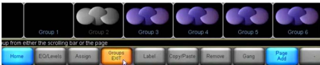
Figure 10-1: Groups Menu
The GROUPS scroll bar in Figure 10-1 shows the status of different Group icons while on the scroll bar.
▶ Group 1 (empty) is being used in the current system configuration.
▶ Group 2 (gray) is assigned to a Module that is not a part of the current system configuration.
Groups 3 through 28 are available for use and are not currently assigned to any other Modules.
Tap and drag the scroll bar to the left/right or tap the << or >> buttons to access additional Group icons.
To add a Group to the system configuration, perform the following steps:
- Tap a Group icon on the scroll bar. The cursor changes to the Group icon.
- Tap somewhere in the work area to add the Group to your system configuration.
- Follow the instructions in section 9.3 to assign Modules to the Group.
10.2 EQ/Levels
Tap the EQ/LEVELS button from GROUPS to display the Parametric EQ, Graphic EQ, and Levels screens for the selected Group. This function is active only when a Group is selected in the work area.
For detailed information relating to all EQ/Levels functionality, please refer to Chapter 6 on page 65.
Module level limits are always adhered to when Group levels are changed. If one Module in the Group would exceed its level limit as a result of a change to Group data, then the change will not be allowed.

Level limits can be adjusted in Designer Mode for unlocked Modules.
10.3 Assign
Changes made to the Group EQ/Levels affect only those Modules assigned to that Group. Before assigning Modules to a Group, make sure the required Modules and Groups are in the work area and navigate to the Groups menu.
10.3.1 Assign One-by-One
To assign one Module to a Group, perform the following steps:
- Tap a Group icon. The icon illuminates yellow.
- Tap TOGGLE ASSIGN to activate the function.
- Tap each Module icon you wish to assign to that Group. Each Module icon's border illuminates yellow indicating it is assigned to the selected Group.
- Tap TOGGLE ASSIGN to deactivate the function.
Module Group assignments can be verified by selecting a Group icon in the work area. The selected Group and associated Module icons will display yellow borders as shown in Figure 10-2.

Figure 10-2: Group Assignment Indication
10.3.2 Assign by Multi-select
It is possible to assign multiple modules to a group by using the multi-select (yellow lasso) function;
- Tap a Group icon. The icon illuminates yellow.
- Use the multi-select to select multiple modules.
- Press ASSIGN.
10.3.3 Assign by Copy/Paste
It is possible to copy the Group assignments for one module to a different module:
- Open the Group menu.
- Tap on a module with the completed Group assignments.
- Tap COPY/PASTE.
- Tap COPY ASSIGNMENT.
- Tap on the module where assignment will be pasted.
- Tap PASTE ASSIGNMENT.
10.3.4 Keep Group Assignment on Module Recall
If the Keep Group Assignment function is disabled (default) on the Modules Store/Recall menu, Group assignments will be lost when a Module is recalled. A warning message will be displayed to confirm this action.
If the Keep Group Assignment function is enabled on the Modules Store/Recall menu, Group assignments will be maintained when a Module is recalled.

Modules will not allow assignment of Group/s if it will result in level limits being exceeded. Warning messages will be displayed if a Group assignment would cause the Module to exceed its level limits.

The first Module assigned to the Group will be used for Group level metering purposes. This metering assignment can be changed later if required; please refer to section 6.2.7.
10.4 Label
The Group label is a user-defined value at the bottom of the Group icon that is useful for identifying the part of the sound system to which the Group communicates (front of house, monitors, down-fill, and so on).
To label a Group, perform the following steps:
- Tap the desired Group icon.
- Tap LABEL and enter a Group label.
- Tap OK.
10.5 Copy/Paste
Select a Group in the work area, and tap COPY/PASTE to view a submenu that transfers attributes between Groups.
10.5.1 Copy
The COPY button is active only when a Group icon is selected. To copy data from a Group, tap the Group icon that contains the data to be copied, then tap COPY.
10.5.2 Paste
The PASTE button is active only when Group data has been previously copied and a Group icon is selected. To paste data to a Group, tap the Group icon in which to paste the copied data then tap PASTE.

The Paste operation overwrites all the destination Group's EQ and Levels settings, but not the Module label or Module assignments.
10.6 Remove
This function removes the selected Group from the current system configuration. To remove a Group, select the Group icon, tap REMOVE, then tap YES to the warning message.
The warning message is displayed only if the Group has Modules assigned to it. The Group icon reappears in the scroll bar indicating it is not currently in use.

A Group can also be removed by dragging the icon back to the GROUPS scroll bar.
10.7 Gang
Tapping this button activates a scroll bar containing all Modules currently assigned to the selected Group, along with a submenu.

Figure 10-3: Group Gang Menu
10.7.1 Gang Xover/Aux or Gang HPF/LPF
This button reads GANG XOVER/AUX when a Group containing Contour Modules is selected, and GANG HPF/LPF when a Group containing Mesa EQ Modules is selected. These functions allow the crossovers, auxiliary output channels, and HPF/LPF settings of Modules on different Frames to be linked together.
When GANG XOVER/AUX is active on a Group containing crossover Modules, the crossovers, HPF/LPF and auxiliary channels of all Modules in the Group are synchronized. A change made in one Module will be reflected in all Modules of that Group. When Gang HPF/LPF is active on a Group containing Mesa EQ Modules, the HPF/LPF will be linked on all Modules in the Group.
To gang the crossover or HPF/LPF of all Modules in a Group, perform the following steps:
- Assign the Modules to a Group. All Modules must be of the same crossover type, such as Classic 3-Way (CL3way), for example.

All Modules must be of the same Module type, such as a Classic 3-Way (CL3way), for example.
- From the GROUPS menu, tap GANG.
- Tap the Module on the scroll bar to select which Module's settings will be transferred to all other Modules in the Group.
- Tap GANG XOVER/AUX (Contour Modules) or GANG HPF/LPF (Mesa EQ Modules).
- Tap YES to the warning message.

Only the XOVER/AUX/HPF/LPF and associated OUTPUT EQ data is ganged. LEVELS data and INPUT EQ (PEQ/BLEO/GEO) cannot be ganged. Use Group EQ/LEVELS to control multiple Modules.

To synchronize all data across multiple Modules, you can use the powerful SUPER MODULE feature. Refer to section 8.8 for details.
10.8 Add Page
The ADD PAGE function is always available from the GROUPS menu and creates additional pages that help manage large systems with many Module and Group icons.
10.9 Discovering Module Group Assignments
While inside the Group menu:
It is possible to tap on a Group on work area and all Modules assigned to the group will have the Module icon's border illuminate yellow. It is also possible to tap on a Module and the Group(s) the Module is assigned to will have the icon's border illuminate yellow. It is possible to tap on a Group down on Scrollbar and all Modules assigned to the group will have the Module icon's border illuminate yellow.
11. Solo/Mute Menu Reference
The functionality provided by the SOLO/MUTE menu provides an invaluable tool for the sound engineer during system setup and optimization. The solo function allows specific Module or Groups to be isolated, instantly muting the rest of the system. This allows for rapid measurement and analysis, including lobe studies in large, complex systems.
Tap SOLO/MUTE from the HOME menu. This action displays a submenu with mute and solo functions for Modules and Groups.
11.1 EQ/Levels
Tap EQ/LEVELS from the SOLO/MUTE menu to display the Parametric EQ, Graphic EQ, XOVER, and LEVELS screens for the selected Module or Group. This function is active only when a Module or Group icon has been selected.

When SOLO/MUTE is enabled, EQ/LEVELS can only be accessed for a Module that is in SOLO mode.
The ability to access EQ/LEVELS from the SOLO/MUTE button bar is necessary as the Lake Controller will exit SOLO/MUTE mode when you navigate to other areas of the user interface. This is a safety feature to ensure that no Modules or Groups are left accidentally muted.
Additionally, context switching is also disabled to ensure that no Modules or Groups are left accidentally muted.
11.2 Solo/Mute Enable
Tap SOLO/MUTE ENABLE button to toggle the SOLO/MUTE functionality ON (orange) and OFF (blue). While the SOLO/MUTE function is on, icons are red when muted or green when in solo mode. All Modules default to solo mode when SOLO/MUTE is first turned on.
Tap a Module or Group icon to keep solo mode active on that Module (or all Modules in the selected Group) and mute all other Modules in the system. Tap the same icon again to UNMUTE all Modules.
Figure 11-1 shows Module B of a Frame in solo mode. The other two Module icons are muted through the SOLO/MUTE function.
![A LAKE 2 Classic 2 Way + 1Auxiliary B LAKE 3 Classic 3 Way 2 and 3 Way ALL A/B DEMO 4LP Linear Phase Brick Wall 4 Way 4 Way Soo/Mute separately - [Pile] to Solo/Mute multiple Modules/Groups EQ/Levels Solo/Mute ENABLE Pile Solo/Mute EXIT - - - - - ALL MUTE](/content/2026/07/1419186/images/e757333b27b23bc89afb29feb35e8d847b058303f9e12fb637737a7cc9c6fa61.jpg)
Figure 11-1: Solo/Mute
11.3 Pile
The Pile function allows for multiple Modules or Groups to solo at the same time.
- Tap SOLO/MUTE ENABLE from the SOLO/MUTE menu. The button illuminates orange.
- Tap PILE. The button illuminates orange.
- Tap a Module or Group icon to solo. Repeat for other Modules or Groups to solo.
- Tap SOLO/MUTE ENABLE again to exit this function.
11.4 All Mute
To mute all Modules in a system, perform the following steps:
- Tap SOLO/MUTE ENABLE from the SOLO/MUTE menu. The button illuminates orange.
- Tap ALL MUTE.
- Tap SOLO/MUTE ENABLE or SOLO/MUTE EXIT to resume normal status.
12. Icon Control Menu Reference
The functionality provided through the ICON CONTROL menu allows configuration of icon size and an option to change the icons to show input and output metering. Pages can be configured to provide an overview of all Modules on the network, providing a system-monitoring interface including both level and limiting activity.
12.1 Meters On/Off
This feature is active for Modules and Groups when an icon is selected. Meters on the icon display input and output levels, limiting, clipping, and the Module label.
Figure 12-1: Icon Metering
To toggle meters on and off:
- Tap ICON CONTROL from the HOME menu.
- Tap METERS ON/OFF. The button illuminates orange.
- Tap the Module or Group icon to toggle between METERS ON/OFF.
- Tap METERS ON/OFF again to exit this mode.
The ICON SMALL, ICON NORMAL, ICON MEDIUM, and ICON LARGE buttons are active only when a Module or Group icon is selected from the main work area and the METERS ON/OFF mode is not selected (i.e., the METERS ON/OFF button is blue). It is also possible to enable/disable the meters on multiple modules at the same time using the multiple select yellow rectangle.
12.2 Fast Meters
There is an option to always get fast meters; otherwise, the meter speed depends on the size of the module icon (i.e., ICON SMALL has slow meters, and ICON LARGE has fast meters, etc.). With FAST METERS enabled, all meters will be fast.

This option is not recommended to have enabled while connected to a large network via WiFi.
12.3 Icon Small/Normal/Medium/Large
Tap these icon size buttons to change the size of the selected Module, Super Module, or Group icon. It is also possible to change the icon size for multiple modules at the same time using the multiple select yellow rectangle.
13. User Preferences Menu Reference
The User Preferences menu provides various functions for customizing the Lake Controller interface.
Tap USER PREFERENCES from the HOME menu to display a submenu containing functions and various additional menus. These functions change settings globally throughout the system.
13.1 Contexts
Contexts allow up to eight views to be stored and retrieved easily using the CONTEXT button, which is available on the far left of the button bar on most screens, identified at [A] in Figure 13-1.

Figure 13-1: Context View Options
The Context menu enables selection of the number of views to be available throughout the system.
To set up four contexts in your system, perform the following steps:
- From HOME, tap USER PREFERENCES.
- Tap CONTEXT, then tap the button labelled [4].
- Tap HOME.
- Navigate to the first screen.
- Tap the numbered context button [A] to move to the next view.
- Repeat steps 4 and 5 until all four contexts are configured.
Tapping the CONTEXT button now allows you to switch instantly between these views.

The last screen viewed is stored under the currently selected context number.
13.2 Delay Units
The DELAY UNITS preference selection is reflected throughout the Lake Controller interface.
This menu provides the option for values to be entered and viewed in feet and meters. Tap the relevant button to change to your required default setting. The system default is milliseconds.
Delay calculations in meters and in feet are performed with the speed of sound being 343.6 meters (1127.3 feet) per second. This is the speed of sound as calculated for an ambient temperature of 20 degrees Celsius (68 degrees Fahrenheit).
13.3 Designer Functions
DESIGNER FUNCTIONS provide a gateway to Designer Mode, an advanced mode of the Lake Controller that provides the engineer with the ability to secure various aspects of the user interface.
13.3.1 Change Password
The CHANGE PASSWORD function is active only when Designer Mode is on. It allows a system designer to password protect access to Designer Mode.
13.3.2 Designer Mode
Tap DESIGNER MODE to toggle Designer Mode ON (orange) and OFF (blue). With DESIGNER MODE ON, the user can access and adjust additional functions throughout the system, including the following:
▶ Global and Individual Overlay access security settings ▶ Crossover and HPF/LPF access security settings ▶ Hidden channels ▶ Factory settings and Level Limits
When DESIGNER MODE is active, the text Designer Mode is displayed on the status bar as shown.

Figure 13-2: Designer Mode Help Text
13.3.3 Global Access
GLOBAL ACCESS function is active only when Designer Mode is on. It allows a system designer to hide or set parts of the system to VIEW ONLY. Refer to chapter 19 for further details.
13.3.4 Module Output Mixing (PLM+ and D Series amplifiers only)
If Module Output Mixing is enabled, it is possible to create a Secondary output routing scheme that enables the combining of outputs for a Module. Applications of this feature include mixing multiple module channel outputs and sending to the same speaker output, in addition to creating frequency-dependant limiters.
The Primary channel sets the ISVPL limiter and Amp Gain settings, so this limiter is after the summation of Primary and Secondary routes.

Ensure LevelLimits limiter values are correct, as when two or more channels are combined, the total level of the combined signal cannot be above 21 dBu. A value over this amount will result in a hard clip, indicated with a module clip on the DSP channel that has the Primary route to the Power channel.
13.4 Keyboard Shortcuts
The KEYBOARD SHORTCUTS button enables (orange) or disables (blue) keyboard shortcut functionality. For details on all available keyboard shortcuts, please refer to chapter 19.
13.5 About
Tap the ABOUT button to view the current Lake Controller software version. Tap anywhere on the display to return to the previous view.
13.6 Graphics
13.6.1 Display Mode
Display Mode provides options to run the Lake Controller in fullscreen mode (default) or various fixed-resolution Window modes to allow for easier parallel use with other Windows applications.

Display Mode is persistent after restarting the Lake Controller. If the Display Mode is changed to an unsupported resolution, this can be corrected manually via the IC.ini file.
13.6.2 Auto Icon Arrange
This button is on by default, automatically placing icons so they do not overlap each other.
13.6.3 Screen Capture
This button changes the UNDO button into a SCREEN CAPTURE button, which stores a bitmap of any screen in the system to the data/user/printout folder in your Lake Controller installation directory.
13.6.4 Animate
This button is on by default, enabling various animation and Graphic effects during use of the Lake Controller. For slower computers or when connecting via remote desktop, it is recommend that this feature is disabled.
13.6.5 Daylight Mode
Daylight Mode provides high-contrast Graphics on a white background, making the Controller easier to view under daylight conditions.
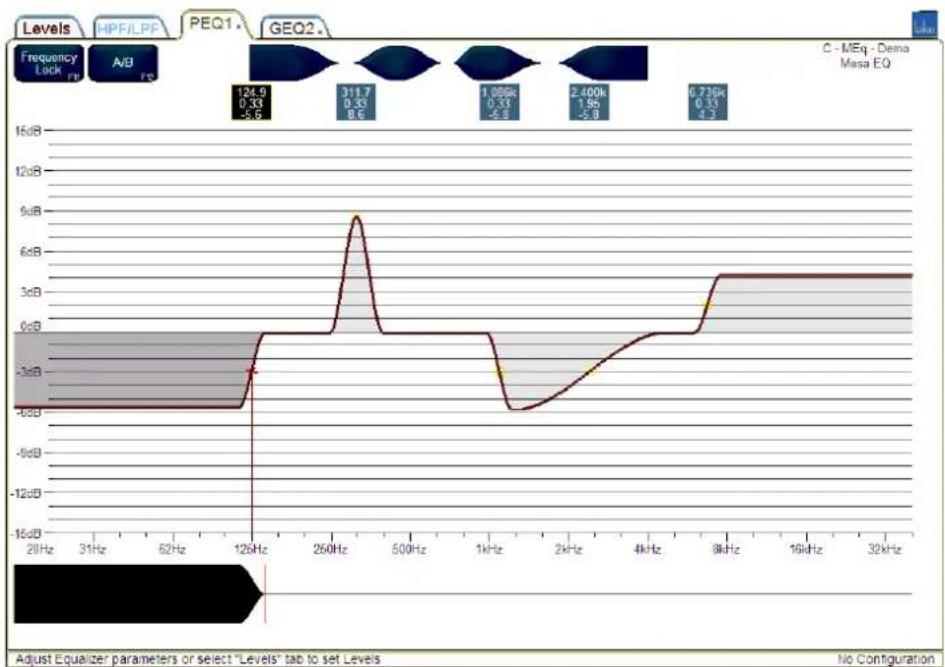
Figure 13-3: Lake Controller in Daylight Mode Figure 13-4:
Tap the DAYLIGHT MODE button to toggle between normal Graphics settings (black background) and the high contrast daylight view (white background).
13.7 Show Mode
Tap SHOW MODE to toggle ON (orange) and OFF (blue). SHOW MODE can be activated during a show to prevent accidental changes. When SHOW MODE is on:
▶ MUTE and POLARITY buttons are disabled on all LEVELS screens. ▶ INPUT MIXER and INPUT MUTE controls are disabled. All changes to EQ and LEVELS are restricted to fine adjustments. ▶ All XOVER screens become unavailable. All HOME menu options are disabled except USER PREFERENCES and NETWORK.
14. Pages Menu Reference
Tap the PAGES button from the HOME menu to display a submenu with functions that manage the main work area of the system, along with the Module and Group icons. The default system setting is a single page, labelled MAIN. Large systems with many Modules and Groups may require additional pages.
The functions described in this chapter may be used to manage pages and copy or move icons across the pages. The following example shows a configuration containing three pages: one containing Groups for main front-of-house EQ and Levels, another for monitor EQ and Levels, and another to store all the Module icons.
![graph TD A["FOH Master"] --> B["Groups - FOH"] A --> C["Groups - Foldback"] A --> D["Modules"] A --> E["FOH Master"] A --> F["Groups - FOH"] A --> G["Groups - Foldback"] A --> H["Modules"] A --> I["FOH Master"] A --> J["Groups - FOH"] A --> K["Groups - Foldback"] A --> L["Modules"] A --> M["FOH Mast…](/content/2026/07/1419186/images/1f36902b23c2fbc9519aefd7e84b539e9a2c1b8969606ba5e8d5aafdd49c0b2e.jpg)
Figure 14-1: Lake Controller Pages
14.1 Cut Icon
The CUT ICON button is active only when a Module or Group icon is selected. To move an icon from one page to another, perform the following steps:
- Tap a Module or Group icon on the work area.
- Tap CUT ICON.
- Select another page using the tabs at top of the screen, or tap ADD PAGE if no other pages exist.
- Tap PASTE ICON.
14.2 Copy Icon
The COPY ICON button is active only when a Module or Group icon is selected. More than one copy of an icon can exist on different pages.
To copy an icon, perform the following steps:
- Tap a Module or Group icon on the work area.
- Tap COPY ICON.
- Tap PASTE ICON.
- Select another page using the tabs at top of screen, or tap ADD PAGE if no other pages exists.

There can be only one instance of an icon on each page.
14.3 Paste Icon
The PASTE ICON button is active only after a CUT ICON or COPY ICON action. When tapped, this button will paste a copy of the icon currently in memory to the currently selected page.

Icons can also be moved by selecting and dragging the icon to a page tab at the top of the screen. Select and drag the icon/s to the required page tab then release in the required location.
14.4 Page Label
The PAGE LABEL button is always active.
To label a page, perform the following steps:
- Select the page to be labeled (top of screen).
- Tap PAGE LABEL.
- Enter the label using either the on-screen or external keyboard.
- Tap OK.
14.4.1 Unused
If a Page is labeled #Unused, the label on the tab will turn gray and any modules moved to this page will not be displayed on the ALL page.
This can be helpful on a system with several 4x module products such as the PLM+ and D Series where only one or two modules are used; this ensures the ALL page displays only the modules that are in use in the system.

If the #Unused page is full, create another page and label by appending a number to the end e.g.
Unused2 etc.

The #Unused page is automatically created if a PLM is frame replaced with a PLM+ or D Series if the "Enable #Unused page" is enabled.
The #Unused page is automatically created if a PLM is frame replaced with a PLM+ or D Series if the "Enable #Unused page" is enabled.
14.5 Page Delete
This function deletes the selected page, including all Module and Group icons, which return to the Module and Group scroll bars.

PAGE DELETE is inactive if the MAIN page or the ALL page is selected.
14.6 Page Add
Tap the ADD PAGE button to add another page to the Lake Controller interface.
14.7 Page Hide
This button is active only in Designer Mode and is used for hiding pages. For further information, please refer to chapter 19.
14.8 Scrolling Pages
The << and >> buttons on the button bar activate if there are more pages than can fit across the screen. Tap these buttons to view pages that are currently out of view, or use the keyboard TAB key.
15. Network Menu Reference
This chapter provides information on the Network menu functions in the Lake Controller. For additional information on network configuration, please refer to chapter 3 and to the separate Lake Network Configuration Guide and Dante configuration literature included in the Lake Controller installation.
15.1 Network
Tap NETWORK to display the network adapters used to connect the Lake Controller to the network. This feature can be used to switch between network adapters or to work offline.
- From HOME, tap NETWORK.
- Tap the required network connection on the scroll bar.
- Tap SELECT NETWORK, and then tap YES to the warning message.
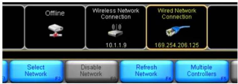
Figure 15-1: Network Menu
If multiple adapters are enabled, any adapters other than the currently selected adapter may be disabled to avoid communication errors.
To disable an adapter, tap the desired network adapter in the scroll bar and tap DISABLE NETWORK. To enable a currently disabled adapter, tap on the desired network adapter and tap ENABLE NETWORK.

The Lake Controller must be running as administrator for the Enable / Disable functions to work.
To update information about the currently selected network adapter, tap the desired network adapter and tap REFRESH NETWORK. To enable multiple Controllers to be connected to the same network, tap the desired network adapter and tap MULTIPLE CONTROLLERS. Please refer to section 15.2 for further details.
15.2 Multiple Controllers
15.2.1 Overview and Menu Options
The Lake Controller system allows multiple Controllers to be connected to the same network. When in this mode, certain functionality is restricted.
The first Controller to connect to a network is called the primary Controller. Any subsequent Controllers are referred to as secondary Controllers.
The following options are available on the MULTIPLE CONTROLLERS submenu:
15.2.1.1 Multi Cont Enable
This button is available only on the primary Controller and is disabled (gray) on any secondary Controllers. When this button is active (orange), multiple Controllers are allowed on the same network. When the button is inactive (blue), only one Controller is allowed on the network.
15.2.1.2 Confirmation Required
This button is available only on the primary Controller and is disabled (gray) on any secondary Controllers. When this button is active (orange), a confirmation dialog box is displayed on the primary Controller when a secondary Controller attempts to connect. If this button is inactive (blue), then additional Controllers are able to connect to the network without primary Controller approval.
15.2.1.3 Analyzer Enable
This button provides the option to disable analyzer data on a per-controller basis (useful when using multiple Controllers). If this button is active (orange), analyzer data will be displayed on this Controller. If this button is inactive (blue), analyzer data will not be displayed. This button is disabled (gray) if the analyzer is not available.
15.2.2 Primary and Secondary Controllers
The primary Lake Controller communicates with the network of Lake devices, and also with secondary Controllers. The secondary Controllers communicate only via the primary Controller.
Primary and Secondary Controllers can be used in either Designer or User Mode (in which various Designer Mode functions will be restricted). The Primary Controller must have a connection to the network for Secondary Controllers to function.
If communication is lost between the primary Controller and the network, all secondary Controllers are suspended with a warning message displayed until the network connection returns.
If the primary Controller is restarted, all secondary Controllers must also be restarted.
If the Controllers become out of sync with the network, the primary Controller must be used to synchronize the network.
In a multiple Controller environment, it is recommended that the primary Controller is either wired to the network or kept within range of the wireless transmitter to ensure that all Controllers can function without interruption.
To ensure correct operation of multiple Controllers, consider the following:
- Ensure the date, time and time-zone are synchronized on all computers.
- Ensure firewalls are correctly configured.
- Ensure each computer has a unique IP address on the same subnet.
- Do not use multiple network adapters if more than one NIC has an IP address on the same subnet.
15.2.3 Restricted Functionality
Various functionality is restricted when multiple Controller mode is active. The following figure shows the top-level menus that are available from the HOME menu when multiple Controllers are enabled; the buttons shown in gray are unavailable.
Note the **PRIMARY** label on the far right of the help text identifies the Controller status and reads **SECONDARY** for all secondary Controllers.

Figure 15-2: Limited Functionality using Multiple Controllers
From within the SYSTEM STORE/RECALL and MODULES menus, both primary and secondary Controllers can STORE SYSTEM files and use the REPLACE FRAME functionality; most other functions in these menus are disabled. SOLO/MUTE functionality is available on both primary and secondary Controllers.
Certain functions on the EQ/LEVELS/XOVER screens are also disabled in multiple Controller mode; any unavailable function is identified by a gray button.
To restore full functionality, the primary Controller has the ability to disable multiple Controllers using the MULTI CONT ENABLE button. Disabling multiple Controllers disconnects all secondary Controllers. The
primary Controller can re-enable multiple Controller mode in the same session and the secondary Controllers will automatically reconnect.

If multiple Controller mode is disabled then restored by the primary Controller, the system configuration will be transferred again to all secondary Controllers to ensure data is synchronized.
15.2.4 Using the Analyzer with Multiple Lake Controllers
If a compatible analyzer is available on the network, Analyzer data can be transmitted and displayed on all Controllers that have the ANALYZER ENABLE button activated.
Each Controller has the ability to disable the analyzer independently. One Controller can view analyzer data while other Controllers continue working without the analyzer data being displayed.
To enable/disable analyzer data on a Controller, perform the following steps:
- From HOME, tap NETWORK, then MULTIPLE CONTROLLERS.
- Toggle the ANALYZER ENABLE button (orange equals enabled; blue equals disabled).
15.3 Working Offline
Working offline enables the Lake Controller to be used even if a network is not enabled or present. This allows offline setup of system configurations.
Therefore, systems can be created or modified when the network of Lake devices is unavailable. To work offline, start the Controller without a network adapter enabled, or select OFFLINE during initial network selection on startup, or tap the NETWORK button and select the network card Graphic labeled OFFLINE from the scroll bar.
A large majority of functions can be used when offline, although some hardware-specific configuration functions are not accessible.

If an existing system configuration has been modified and stored while offline, the new values will take effect when the system configuration is recalled with an online Lake device network.
15.3.1 Virtual Frames
Virtual Frames can be used while working offline. A Virtual Frame provides the same functions as online Modules; Module files can be recalled, stored, copied and pasted, and the Virtual Frames can be stored as part of a system configuration.
The virtual frame folder contains all configurations of Lake-enabled products to allow for offline configuration:

Figure 15-3: Virtual Frame Icons
To use Virtual Frames, perform the following steps:
- Tap the Virtual Frame icon that you require. The cursor will represent the relevant number of Module icons.
- Place the Virtual Frame in the work area. The majority of functions are available, enabling full offline configuration.
Virtual Frames do not have a device identifier, and therefore a replace function is used to assign the Module to an online Lake device.
Refer to section 4.3 for details about Contour and Mesa Modules.
15.3.2 Replacing Virtual Frames with an Online Device
The MODULE STORE/RECALL or COPY/PASTE/REPLACE functions can be used to transfer the data from a Virtual Frame to an online Frame.
Individual Modules created offline can be stored as Module files and recalled into an online device.
Offline system configurations can be stored and recalled, and then each Frame can be replaced with an online device.
Please refer to section 8.4.3 for detailed information on the REPLACE FRAME functionality
16. Communication and Synchronization
The Lake Controller and Lake devices communicate via an Ethernet network. All updates made using the Controller are transmitted in real time to the network of devices. Both the Controller and the devices store all required information, which results in two copies of the data for each Module:
▶A copy stored in the Lake Controller software ▶A copy stored in the Lake device hardware (aka Processor)
This data redundancy ensures an extremely high level of confidence in communicating over an Ethernet network that can be subjected to other network traffic, as well as interference or lost data packets due to a noisy transport such as wireless Ethernet configurations.
If there is ever a discrepancy found between these two data records, the Controller immediately notifies the user that the two data records are out of sync, and provides a choice to either continue using the settings on the device (aka Processor) or to use the settings in the Controller software. Discrepancies are typically caused by making adjustments via the device front-panel interface while the Controller is offline.
This chapter provides useful terminology definitions and reference information for dealing with communication and synchronization issues.
16.1 Offline Modules
A Module that cannot be found on the network is referred to as OFFLINE. This can occur for the following reasons:
▶The device is turned off. ▶The device is not connected to the network. The wireless transmitter is out of range or turned off. ▶Network cabling or hardware is faulty.
Virtual Frames always show offline because they have not been assigned to a device, and therefore exist only in the computer's data record.
16.2 Communication/Network Errors
The Lake Controller displays communication or network problems highlighted in red at the bottom right of the screen:
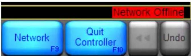
Figure 16-1: Network Related Warning Messages
If a network problem persists, the affected Modules become offline as described above. To rectify the situation, check all network connections. If using a wireless access point, make sure the computer is within range.
16.3 Synchronization
This section describes the various synchronization processes between the Lake Controller software and Lake devices.
16.3.1 Resync Process
The resync process ensures that the data in the Lake Controller software and on the Lake devices (aka Processors) is synchronized, or that the operator is informed of differences between the two copies of data.
The resync process compares the data in the Controller software with that stored on the devices. If differences are found, the Controller software informs the user that Modules are out of sync.
A resync occurs when:
▶ A system configuration file is recalled ▶ An offline Module becomes online ▶ A network or communication error occurs
The Controller provides a general PLEASE WAIT message if any Module is syncing, along with a RE-SYNCING indication on the Module icon as shown in Figure 16-2.

Figure 16-2: Please Wait and Re-Syncing Indications
16.3.2 Out of Sync
The Lake Controller and Lake devices could become out of sync for the following reasons:
An update was made using the Controller software while a device was offline.
▶ A communication or network error occurred during an update.
When the affected Modules return online, the Controller compares its data with that in the devices. If differences are found, the Controller highlights which Modules are out of sync.

OUT OF SYNC Modules or related Groups are set to VIEW ONLY. No further changes can be made until the Lake Controller (Computer) and Lake devices (Processors) are synchronized.

Audio will not be affected unless the USE COMPUTER SETTINGS option is selected; in this instance audio may change depending on the differences from the current Processor settings.
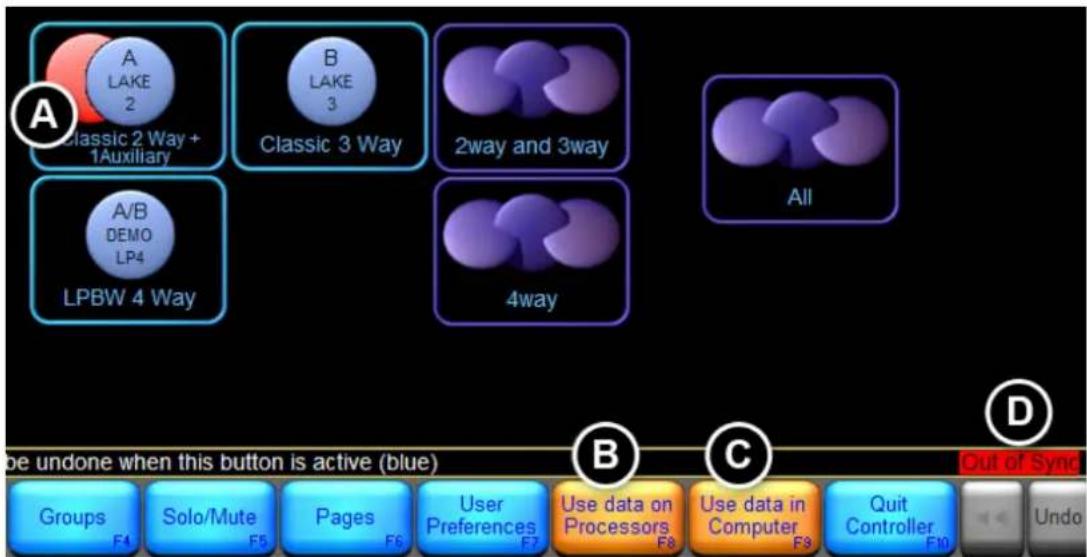
Figure 16-3: Out of Sync Notifications
(A) The red disc behind the Module icon indicates that the Module is out of sync. (B) Flashing USE DATA ON PROCESSORS button. (C) Flashing USE DATA IN COMPUTER button. (D) A warning message appears that is visible from any screen in the system.
16.3.3 Updating All Devices with Computer Settings
To update all devices with the information stored in the Controller, perform the following steps:
- From the HOME menu, tap the flashing USE DATA IN COMPUTER button.
- Tap YES on the warning message to confirm the action.

This option may result in an audible effect, as the data in the devices will be overwritten with the data stored in the computer.
16.3.4 Updating the Controller with Device Settings
To update the Lake Controller with the information stored on the devices, perform the following steps:
- From the HOME menu, tap the flashing USE DATA ON PROCESSORS button.
- Tap YES on the warning message to confirm the action.

Audio will not change if this option is selected.
16.3.5 Synchronizing the Lake Controller and Devices
In the following example, a communication error occurred while the PEQ1 overlay was being updated using the Controller. Figure 15-2 shows an example of the COMPUTER SETTINGS view, along with letters marking key information.

Figure 16-4: Computer Settings on the PEQ1
The referenced information in Figure 16-4 is described below.
▶ A OUT-OF-SYNC Modules are set to VIEW ONLY pending synchronization. ▶ B The settings currently viewed are: COMPUTER - Frame/Module name highlighted in red as offline PROCESSOR - Frame/Module name displayed in blue text as online ▶ C The main part of the screen changes to show the Computer and Processor settings as selected. ▶ D The help text shown here indicates the type of data that is out of sync. Navigate to the relevant section of the system to view/update. ▶ E The OUT OF SYNC warning message is visible on all screens. ▶ F This button changes labels depending on the currently selected view. SHOW PROCESSOR - when viewing computer settings SHOW COMPUTER - when viewing device (Processor) settings ▶ G Tapping this button updates either the computer or the device with the settings being viewed.
To compare and update settings stored in the Lake Controller software and Lake devices, perform the following steps:
- From the HOME menu, tap a Module icon that is out of sync. An out-of-sync Module is indicated by a red disc behind the normal Module icon.
- View the help text [D] that advises which parameters are affected.
- Navigate to the relevant EQ/LEVELS page. Computer settings are displayed by default.
- Tap SHOW PROCESSOR/SHOW COMPUTER [F] to compare settings.
- Decide which settings to use, and tap USE THESE SETTINGS.
- Repeat the process for each out-of-sync Module.
Alternately, all Modules can be updated with the USE DATA IN COMPUTER or USE DATA ON PROCESSOR functions.
16.3.6 Audible Changes when Synchronizing
If a Module becomes out of sync while audio is being processed, choosing to synchronize with the Controller could affect the sound, depending on the values that are out of sync.
If the Controller EQ/XOVER/LEVELS settings differ from those currently used by the device, the audio signal may change or be momentarily muted while settings are configured if USE DATA IN COMPUTER is selected.
17. Faults and Warnings
17.1 Faults and Warnings Indication
Each Lake device has different warning and fault messages relevant to that device.
When a warning or a fault occurs, this is typically indicated on the front panel of the device (where applicable), and may also be indicated in the Lake Controller. Please consult the Operation Manual for each device for the associated Faults & Warnings and where they will appear.
In the Lake Controller, error messages are displayed in a few locations:
On the Module icon visible on the Main page via Home menu, or on additional pages if present
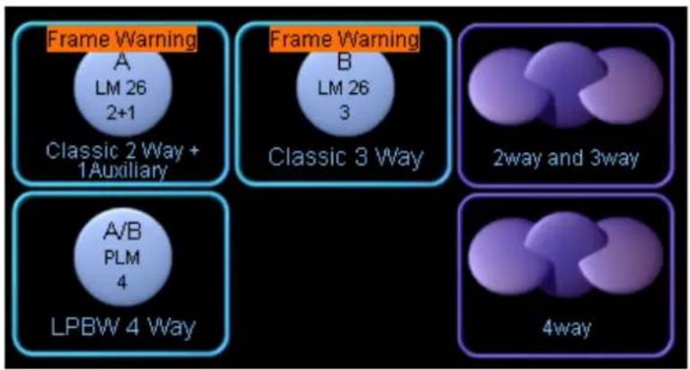
Figure 17-1: Module Icon Warning Indication
On the Module icon on the ALL page
![graph TD A["Main"] --> B["PLM A/B - LPBW 4..."] C["All"] --> D["TEMP WARNING"] C --> E["TEMP WARNING"]](/content/2026/07/1419186/images/3f345281cabc6e7d5f36ded6302afcab226634ce3b698237c76f9248947e7e22.jpg)
Figure 17-2: All Page Warning indication
Via the Module/Global Events & Control > Events tab

Figure 17-3: Global Events Warning Indication
Via the Global Events log file (for post-session analysis)
| A | B | C | D | E | F | G | H | I | J | |
| 1 | Date Time Duration FrameID Frame Module Channel Type Source Description | |||||||||
| 2 | 2014-01-29 12:43:22 - 9a000014:703bd501 LM 26 - - UserAction Unknown Frame removed | |||||||||
| 3 | 2014-01-29 12:43:22 - 72000010:9e598c01 LM 26 - - UserAction Unknown Frame removed | |||||||||
| 4 | 2014-01-29 12:42:51 - - - UserAction Unknown Frame added | |||||||||
| 5 | ||||||||||
| 6 | ||||||||||
Figure 17-4: Global Events Log File
When the Faults and Warnings indications are not visible in a particular view (e.g. EQ/Levels or I/O Config) a traffic-light style indication is displayed in the bottom-right corner of the screen. A red light indicates and fault and a yellow light indicates a warning. Navigate to the ALL page identify the issue further and ascertain any action to be taken.
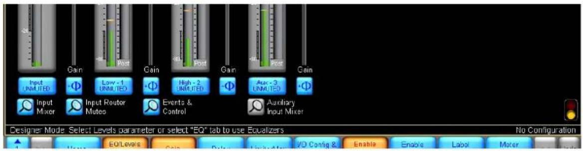
Figure 17-5: Faults and Warnings Indication via Global Status Indicator on Levels screen in lower right corner
18. Analyzer Plug-in
18.1 Overview
The analyzer plug-in provides an interface between the Lake Controller and third-party audio analyzer software products. The plug-in displays measurement results within the Lake Controller, and passes control information from the Lake Controller back to the third-party analyzer software. This communication link can be provided on the same host computer, or between computers over an Ethernet network as Figure 18-1 and Figure 18-2 illustrate.
![graph LR A["Lake Controller Software"] <--> B["Analyzer Plug-in Interface"] B <--> C["3rd Party Analyzer"]](/content/2026/07/1419186/images/a9ed53e48ebdaebbce927f55bf21ff9864ca8f5cbe09e0a86329cea3d1e906ab.jpg)
Figure 18-1: Single host computer
![graph LR A["Lake Controller PC"] --> B["Lake Controller Software"] A --> C["Analyzer Plug-in.dll"] C <--> D["Ethernet Network"] D <--> E["Analyzer Computer"] E --> F["3rd Party Analyzer"]](/content/2026/07/1419186/images/71140ef94ee60cf3bafd1bdeefbffe489ef72c84fa345f9a584deed9cc75f82f.jpg)
Figure 18-2: Two computers connected across Ethernet network
Figure 18-3 shows a practical example connection for connecting the Lake Controller using two computers. The analyzer PC (running the third-party analyzer software with associated plug-in functionality) has a wired connection to an Ethernet switch that connects the Lake network. A wireless tablet PC running the Lake Controller is connected to the same switch using a wireless access point. This configuration allows the analyzer results to be transmitted via a wireless access point to the Lake Controller.

Figure 18-3: Example network configuration
For further information on networking and hardware configuration, please refer to chapter 3 of this Operation Manual and your hardware device Operation Manual.
18.2 System Requirements
To use the analyzer plug-in, the following items are required:
- A Microsoft® Windows® PC with a fully registered installation of an approved analyzer meeting the computer requirements for the analyzer. Supported analyzers include:
▶ Rational Acoustics® Smaart® v7 / v7 Di / v8.0.2 and newer
▶ AFMG® SysTune
WaveCapture™ Live-Capture™ Light / Live-Capture Pro
▶ Additional third-party analyzers approved in the future
- A Windows PC with an installation of the Lake Controller v6 or later, meeting the Lake Controller minimum computer requirements as specified in section 2.1.
Operating the Lake Controller and the third-party analyzer on the same computer may result in slow performance even where the required minimum specifications are met. The Lake Controller is graphic intensive, and audio analyzer software FFT calculations are CPU intensive; therefore, the performance of the graphics card is important. A graphics card with slow performance or low video memory will reduce computer performance by the transfer of rendering and display data. Please ensure that the graphics card driver is updated to the latest version available from the graphics card manufacturer; drivers shipped with Microsoft Windows are generic and may not take full advantage of video card resources.
18.3 Analyzer Plug-in Quick Start Guide
The analyzer plug-in relies on correct configuration of the third-party analyzer for the analyzer functionality to operate correctly in the Lake Controller. When the Lake Controller starts, it verifies if an approved and correctly configured analyzer can be found on the local machine or on the selected network.
The following steps may need to be completed in your software analyzer to enable successful connection to the Lake Controller:
- Start the analyzer software.
- Enable API / external communication.
- Create new measurement routing pairs (groups) & associated measurement configurations.
- Adjust all levels for optimal gain structure and verify generator levels.
- Start both spectrum and transfer functions and verify measurements are working correctly in the analyzer.
- Start the Lake Controller.
If the Lake Controller detects a valid analyzer on the network, the F10 button will read ANALYZER, providing access to the submenu for further controls. Please refer to section 18.4 for details.
If the Lake Controller cannot find a valid analyzer, the F10 button on EQ and XOVER/HPF overlays will read ANALYZER TAP TO SEARCH. Tapping this button initiates a network search for approved and correctly configured analyzers; during the search the button reads ANALYZER SEARCHING.

Please refer to your analyzer documentation for further information on configuring your chosen third-party analyzer software.
18.4 Function Reference
This section details each function of the analyzer functionality available via the Lake Controller software. The Analyzer submenu provides access to enter the three types of measurement mode: Spectrum, Spectrograph, and Transfer functions. The following sections explain these modes and their functions.
18.4.1 Global Control Functions
The following functions affect the overall operation of the third-party analyzer. These functions are provided on the button bar of the top-level interface of the Analyzer submenu.
![graph LR A["Home"] --> B["Spectrum RTA"] B --> C["Spectro-Graph"] C --> D["Transfer"] D --> E["Pause"] E --> F["Signal Generator"] F --> G["Measurement Selection"] G --> H["Spectrum Properties"] H --> I["Transfer Properties"] I --> J["Analyzer EXIT"]](/content/2026/07/1419186/images/3c018569242f723050dd3f40172c452875bbd99c535eb66539f493504496e34b.jpg)
Figure 18-4: Top Level Analyzer submenu
18.4.1.1 Pause
This command pauses the analyzer in all modes of operation, and the last measurement trace remains frozen on the screen. Pause is a toggle command; to resume the analyzer tap the Pause button again.
18.4.1.2 Signal Generator
Tapping this button turns the analyzer's signal generator on or off. When the button is selected (orange), the Signal Generator is turned on. Use the third-party analyzer software interface to select the type of generated signal or to adjust the signal generator gain.
18.4.1.3 Measurement Selection
Tapping this button displays a scrollbar displaying available measurement configurations that have been pre-configured in your third-party software analyzer.
18.4.2 Spectrum RTA Measurement Mode
The SPECTRUM real-time analyzer (RTA) display provides real-time spectrum analyzer functionality. This display plots the spectrum (magnitude values by frequency) of the channel selected for measurement via the third-party analyzer software. The SPECTRUM RTA plot assigns magnitude to the (vertical) y-axis and frequency to the (horizontal) x-axis.
When the SPECTRUM button is selected, the Lake Controller will show the SPECTRUM display on EQ and Auxiliary Overlays.

Figure 18-5: Spectrum measurement mode
The y-axis scale of the SPECTRUM RTA is displayed on the right side of the Lake Controller interface. The SPECTRUM PROPERTIES button provides access to additional functions.

Figure 18-6: Spectrum Properties submenu
18.4.2.1 Averages
Averaging methods and calculations may vary depending on the analyzer being used, and the available options will be displayed in the scrollbar accordingly. Please refer to your analyzer documentation.
Upon entering the AVERAGES submenu, the Lake Controller displays a scrollbar with available averaging schemes. Tap the desired averaging period, then tap the AVERAGES SELECT button. The status text between the scrollbar and the button-bar shows the active measurement parameters.

Figure 18-7: Averages submenu scrollbar
18.4.2.2 Amplitude Range
▶ Move Primary Up:
Move displayed range upward to show higher magnitudes.
▶ Move Primary Down:
Move displayed range downward to show lower magnitudes.
▶ Zoom Primary In:
Magnify displayed vertical range for most plot types; narrows magnitude range for Spectrograph.
▶ Zoom Primary Out:
Decrease magnification of vertical range for most plot types; widens magnitude range for Spectrograph.
18.4.2.3 Banding
The BANDING submenu provides options for the horizontal (x-axis) scaling of the RTA; whole-octave, 1/3-octave, 1/6-octave, 1/12-octave, and 1/24-octave resolutions.
18.4.3 Spectrograph Measurement Mode
The Spectrograph displays frequency content of an input signal over a period of time. Instead of displaying results for one measurement at a time (whether averaged or instantaneous), as per the Spectrum display, the Spectrograph displays a measurement history over an adjustable period of time.
A Spectrum analyzer displays magnitude values for each fractional octave frequency band indicated by vertical bars of varying height; a Spectrograph indicates the "height" using a range of colors to indicate higher or lower magnitude.
The Spectrograph displays three-dimensional data (time, frequency, and energy) on a two-dimensional plot with time on the y-axis, frequency on the x-axis, and magnitude represented by color. Exactly which color represents which magnitude value is determined by the magnitude range specified.
Figure 18-8: Spectrograph measurement mode
18.4.3.1 Colormap Range
The magnitude range of the Spectrograph colormap is displayed on the top of the Spectrograph display. Two edit fields are provided to adjust the minimum and maximum range values for the colormap. To adjust a value tap either field to display the on-screen keyboard.
Figure 18-9: Colormap range
18.4.3.2 Speed
Two buttons are provided to increase or decrease the speed of the Spectrograph. By adjusting the speed of the Spectrograph, you can increase or decrease the amount of time it takes for data to traverse the display.
Figure 18-10: Speed controls
18.4.3.3 Spectrograph Properties
The Spectrograph measurement mode is controlled by all of the settings under Spectrum Properties, as detailed in section 18.4.2 on page 219.
18.4.4 Transfer Function Measurement Mode
The analyzer's real-time Transfer Function measurement capability is a useful tool for setting up sound system equalizers and crossovers. The Transfer Function is calculated by comparing the signal on input to a system (reference) to the signal on the output of the system (measured).
By comparing what goes into a device or system with what comes out, the transfer function calculates its frequency (magnitude and phase) response very precisely. A major advantage of this dual-channel approach is that it works with a wide variety of test signals, including music or other recognizable program material.
To make a transfer function measurement, a test signal is split at the source and sent to both the system under test and back through the analyzer as a reference signal. The output of the system under test is returned to the analyzer as the measurement signal.
![graph LR A["Signal Source"] --> B["Device or System Under Test"] B --> C["Measurement Signal"] C --> D["Computer"] D -->|Reference Signal| B](/content/2026/07/1419186/images/186fdbeda14c84818370477707f2f8bff20ae97b613c770efc768ea0a4c56ca7.jpg)
Figure 18-11: Block-diagram of Transfer function measurement
In Transfer Function mode, calculations are performed using audio data from the two inputs. This data is compared and displayed as a single trace showing the relative magnitude difference between the two signals frequency by frequency.
The default Transfer Function mode Magnitude display plots magnitude values on the y-axis with 0 dB in the center and positive and negative decibel values above and below the zero line. The x-axis of the plot shows frequency and is normally displayed in logarithmic scaling with grid lines at octave intervals. On the standard magnitude display, a value of 0 dB for a given frequency data point represents an equal amount of energy (that is, a relative difference of zero) in both the reference (system input) and measurement (system output) signals at that frequency. A positive or negative decibel value for a given frequency indicates more or less magnitude in the measurement signal relative to the reference signal at that frequency. The Phase display in Transfer Function mode is a second plot showing the relative difference in phase between the two signals for each frequency.
In most cases there is a distance between the loudspeaker and the measurement microphone. This distance creates a propagation delay (the sound travelling through the air) which must be compensated for.
When a transfer function channel is started a reference channel must be selected. Press FIND to find the delay so the reference signal can be adjusted to the same delay.

Figure 18-12: Transfer function measurement mode
The y-axis scale of the Transfer Function is displayed on the right-side of the Lake Controller interface. The controls at the top of the Transfer Function display provide easy access to common controls as described below.
18.4.4.1 Reseed Avg
Reseed Averages clears the averaging buffers (used to increase the stability of the live traces); the trace will require a short period of time to re-stabilize while the buffers are filled. This function is not available for all analyzers, or may be automated; please refer to your analyzer documentation for further details.

Changing the number of averages, FFT size, or sampling rate, or switching between main display modes, also reseeds the averaging buffers.
18.4.4.2 Delay Controls
The Delay controls are grouped together at the top of the screen as shown in Figure 18-13 when Transfer mode is selected. These controls are used to provide signal alignment between the reference and measurement signals for transfer function measurements.
Figure 18-13: Transfer function delay controls

Delay must be adjusted to provide a meaningful measurement. Delay compensates for the system propagation delay, the time taken to create sound through the system and to travel through the air.
The Delay (ms) value is displayed in the Delay edit field. To change the delay value, tap this edit field and enter the required delay using the on-screen keyboard.
The Delay+ and Delay- buttons to the right of the Delay edit field can be used to decrease and increase the current Delay setting by 0.02 milliseconds.
The FIND button identifies the time offset (delay) between two input signals by measuring the impulse response of the device or system under test.
The TRACK button continuously measures and adjusts the delay between the reference and measured signals. This feature is CPU intensive and should only be used when the distance between a measurement microphone and the signal under test is constantly changing.
Please refer to individual analyzer documentation for further information.
18.4.4.3 Transfer Properties
The Transfer Properties button at the bottom of the interface provides access to Transfer Function specific functions.

Figure 18-14: Transfer function properties submenu
18.4.4.4 Averages
Please refer to section 18.4.2.1 on page 220.
18.4.4.5 Amplitude Range
▶ Move Primary Up: Moves displayed range upward to show higher magnitudes. ▶ Move Primary Down: Moves displayed range downward to show lower magnitudes. Zoom Primary In: Magnifies the displayed vertical range for most plot types or narrows the magnitude range of the Spectrograph display. Zoom Primary Out: Decreases magnification of the vertical range of the primary display for most plot types or widens the magnitude range of the Spectrograph display.
18.4.4.6 Smoothing
Smoothing is a graphical averaging available only in Transfer Function mode. This feature helps reduce jagged display on the Transfer Function trace, helping to more clearly visualize the overall system response.

Figure 18-15: Smoothing submenu
18.4.4.7 Coherence
Selecting the Coherence button will turn on the Coherence trace display. The Coherence is displayed in red in the top-half of the screen. The Coherence y-axis scale is displayed in red on the right side of the display.
Coherence is a measure of quality (such as signal-to-noise ratio and time-matching) between signals in a transfer function measurement. Coherence values are given as a percentage, where 100% equals perfect coherence; values closer to one equal improved quality and therefore more accurate results. It is important to note that low coherence values do not necessarily mean your data is untrustworthy. This is particularly true when making acoustic measurements in environments with many reflections where a lot of averaging is required.
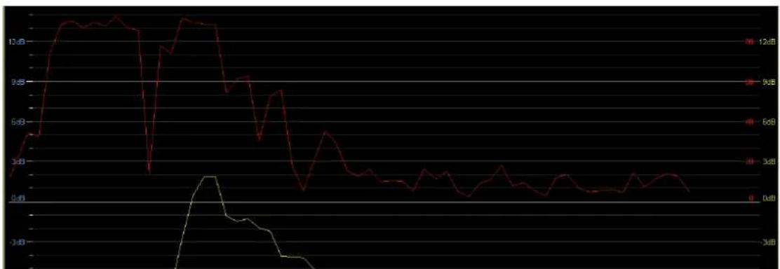
Figure 18-16: Coherence display
18.4.4.8 Phase
Selecting the Phase button will turn on the Phase trace display, shown as a blue line across the screen.
Figure 18-17: Transfer Function showing Phase (blue line)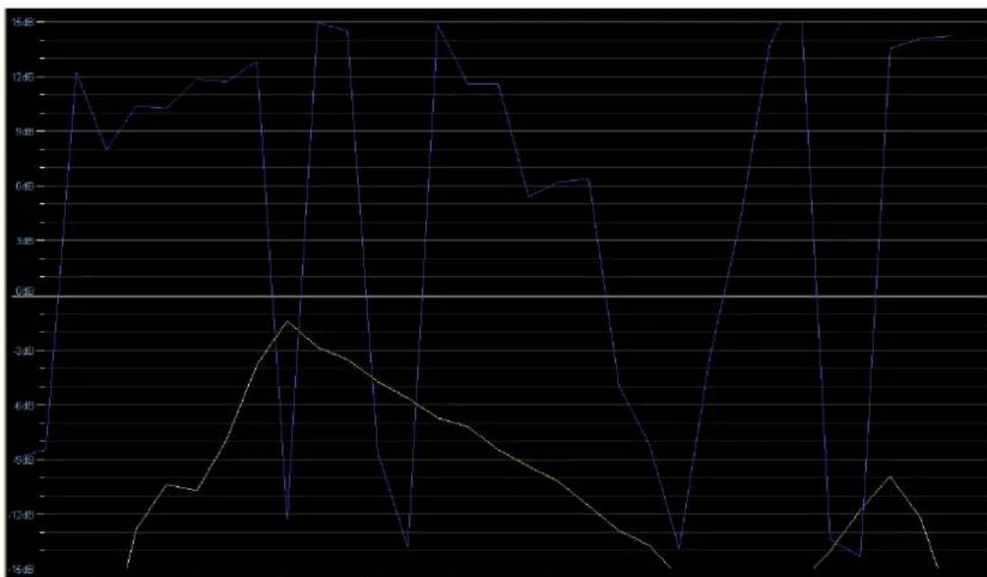
18.4.4.9 Phase Properties
The Phase Properties button provides access to Phase-specific functions.
Phase Normal / Phase Alternate
On the default Phase display plot, all phase values are plotted within a 360° range of +180° to -180°, with 0° in the center [wrapped phase]. This 360° range represents one complete cycle of delay at any given frequency. You can also choose to view the phase within a 360° range of 0° to 360° (alternate phase). This is useful if there is a reverse of signal polarity within your transfer function measurement setup. Please refer to your analyzer documentation for further information regarding phase and the implementation of these options.
18.4.4.10 Invert
Pressing the INVERT button swaps the inputs to the Transfer Function calculation, so the analyzer divides the reference signal by the measurement signal. This feature is mainly used when you want to display the inverse (upside-down) magnitude response curve of an EQ or processor channel to facilitate using the room or system response as a template for setting EQ filters.

Figure 18-18: Invert enabled
19. Designer Mode Menu Reference
The Lake Controller software provides two modes of operation: User Mode and Designer Mode. This chapter describes Designer Mode.
19.1 Designer Mode Basics
Various important functions that Designer Mode activates include:
▶Global Access security - Individual overlay/screen access security ▶Level Limits ▶Factory levels (Adjust Factory mode) ▶Password protection of Modules and base configurations ▶All-pass filters ▶Designer Worksheets ▶Polarity locking
This chapter provides detailed descriptions of these functions. An example system design illustrates the utility of Designer Mode functions. A quick reference guide provides a high-level overview of Designer Mode functions.
This document refers to loudspeaker Modules in the examples, although all features (with the exception of crossovers) also apply to Mesa EQ Modules.
19.1.1 Security Levels
Designer Mode provides three levels of password-protected security.
19.1.1.1 Global
At the global level, a simple selection makes system-wide changes that affect what can be seen or adjusted in User Mode. A system designer can choose to hide any combination of LEVELS, PEQ, GEO, BLEQ, XOVER, AUX, HPF/LPF. These items can also be set to View Only, allowing a User Mode operator to view but not change information as required.

Global Designer Mode settings are stored in the system configuration file.
19.1.1.2 Module
Individual EQ overlays and crossover tabs can be hidden or set to View Only. Additional settings normally invisible in User Mode can also be adjusted and hidden at the Module level.
At the Module level, changes are specific to individual Modules and Groups. Discrete password protection can be applied to Modules, providing an additional level of security.
19.1.1.3 Base Configuration
Base configuration is the lowest level of Module security, enabling the system designer to define an underlying base EQ curve and crossover settings along with factory levels and level limits. A system designer can restrict what can be seen or adjusted and provide optional password protection to the underlying settings.

The Lake Controller is not shipped with base configuration files. These can be created if required using default Module files.
19.1.2 Designer Mode
The functions available in Designer Mode can be used with or without password protection. By default, the Designer Mode password is empty, allowing unprotected access to Designer Mode in a new installation of the Lake Controller software.
To access Designer Mode:
- From Home, tap USER PREFERENCES.
- Tap DESIGNER FUNCTIONS.
- Tap DESIGNER MODE.
Additional buttons on the button bar become active, providing functions specific to Designer Mode.

Figure 19-1: Accessing Designer Mode
When Designer Mode is active, the label DESIGNER MODE appears before any other help text above the button bar.

Figure 19-2: Designer Mode Help Text
19.1.2.1 Password Protection of Designer Mode
Each software installation has one Designer Mode password. This password is stored on the host computer and is relevant for any system configuration.
To password protect Designer Mode, perform the following steps:
- Tap CHANGE PASSWORD.
- Enter a password, and tap OK.
- Confirm the password, and tap OK.
It is important that you record the Designer Mode password in a safe place. Once the password is set, it will always be required to enter Designer Mode.

If the Designer Mode password is forgotten, please email support@lakeprocessing.com for details on password retrieval.
19.1.2.2 Simple Designer Mode System Security
If multiple levels of security are not required for your Lake Controller installation, exiting Designer Mode activates all security features described in this document without needing to lock or password protect individual Modules or base configuration files.
19.1.3 Designing and Protecting a Lake Controller System
This section describes how to use Designer Mode to protect your system by developing an example system with one Lake device. The example includes detailed instructions to define a base configuration, lock individual Module level settings, and enforce global security

An online Lake Controller and Lake device network is required for the following tutorial.
19.1.3.1 System Setup for Designer Mode Tutorial
Follow the steps below to prepare for the tutorial.
To access Designer Mode, perform the following steps:
- From HOME, tap USER PREFERENCES.
- Tap DESIGNER FUNCTIONS.
- Tap the Designer Mode button and enter your Designer Mode password if prompted. (If the Designer Mode button is orange, you are already logged in to Designer Mode.)
- Tap HOME to return to the MAIN menu.
- Place the Modules of a factory-reset Lake device in the work area.
To label the Frame and store the system:
- Tap STORE/RECALL EXIT, then tap LABEL & LOCK.
- Tap LABEL FRAME, enter 'Lake' as the Frame name, and tap OK.
- Tap HOME, then SYSTEM STORE/RECALL.
- Navigate to or create a folder in which to store the file.
- Tap NEW STORE, enter the file name as 'Designer Mode Tutorial', and tap OK.
- Your system configuration is now ready for the following tutorials.
19.2 Designer Mode Security
19.2.1 Security for the Base Configuration
A base configuration file contains EQ, levels, crossover, and HPF/LPF information for a particular speaker type. A base configuration file can be used to create a standard starting point for a particular make and model of speaker; this can then be used in a variety of system configurations and fine-tuned using Module and Group settings.
The base password is stored with the base configuration file preventing access to locked data even in Designer Mode. Using a base password allows hiding of your custom settings from any Lake Controller user.

Base Configuration files hide EQ curves, crossovers, or high-pass and low-pass filters, and convert Group and Module levels to hidden Factory values. The use of base configuration files is recommended for
experienced Lake Controller users who require this additional level of security and functionality.

Module files provide additional functionality to base configuration files and can be used instead of base configuration files in most circumstances.
19.2.1.1 Crossover and Output EQ
All information in the XOVER screen (Lake Contour) or HPF/LPF screen (Mesa EQ) is stored in the base configuration file, including crossover frequencies, crossover type (for example, Bessel, Butterworth, or Linkwitz-Riley), along with any output-specific EQ, HPF/LPF settings, and crossover access status. All data in the XOVER screen can be adjusted for each Module, unless the designer has applied security to the base configuration file.
A base configuration file cannot be recalled into a Module running a different DSP program. For example, a two-way base configuration file cannot be recalled into a Module that is currently running a three-way Module program; a two-way Module program must be recalled first.
19.2.1.2 Input EQ (PEQ, BLEQ & GEO)
All Module and Group EQ overlays are combined and stored as an invisible default EQ curve for the new base configuration. Once stored in the base configuration files, this default EQ curve cannot be viewed or adjusted, although further EQ overlays can be created at the Module or Group level. When the new base configuration file is recalled into a different Module, the main EQ appears flat. Output-specific EQ from the XOVER or output EQ screens can still be viewed or adjusted, unless the system designer has protected it.

The EQ curve created in the input EQ overlays is separate from any output-specific EQ created on the XOVER/AUX pages.
19.2.1.3 Levels
With the exception of the MaxRMS Limiter Corner, Attack and Release, the current Module and Group levels are combined and stored as factory levels when a base configuration file is stored. The factory levels can be viewed and adjusted in Designer Mode after activating the ADJUST FACTORY option in the LEVELS/METER OPTIONS menu.
Level Limits, also stored with a base configuration file, can be viewed and adjusted from LEVELS/METER OPTIONS/LEVELS LIMITS.
19.2.1.4 Base Configuration Tutorial
This tutorial illustrates important features of base configuration files, using loudspeaker Modules as the example. For Mesa EQ Modules, use the only output available on each Module and ignore the steps regarding crossovers.
To adjust levels and level limits, perform the following steps:
- Navigate to the GAIN levels page of Module A.
- Adjust the Output 2 gain to -9 dB.
- Tap the DELAY button and increase Output 3 delay to 6 ms.
- Tap METER OPTIONS, then tap LEVEL LIMITS.
- Select GAIN/DELAY LIMITS.
- Enter 0 (zero), and tap OK.
- Tap the MAX DELAY value highlighted in blue for the input channel. This is located on the left of the screen, second from bottom, and should initially read 1800.00.
Setting a maximum value identical to the minimum value removes the fader when in User Mode, or when the base configuration file or Module is locked.
To adjust crossover settings, perform the following steps:
- Tap the EQ tab (top left) and select XOVER (Contour) or HPF/LPF (Mesa EQ).
- With the first output (low frequency) selected, tap CROSSOVER SELECT.
- Select 36 dB Butterworth from the scroll bar.
- Tap CROSSOVER SET, then tap YES to the warning message.
- Tap HPF ENABLE located at the top left of the screen.
- Tap XOVER FUNCTIONS from the button bar, then tap CROSSOVER VIEW ONLY. This hides the crossover screen or HPF/LPF screen when in User Mode, or when the base configuration/Module is locked.
To add EQ, perform the following steps:
- Tap PEQ1 and add a low-shelf filter around 80 Hz, with 3 dB of gain.
- Tap HOME.
To lock the base configuration, perform the following steps:
- Tap MODULES, then tap Module A to select it.
- Tap LABEL & LOCK. The options shown in Figure 19-3 are displayed.

Figure 19-3: Label & Lock Menu Options
- Tap SET BASE PASSWORD, type 'Demo', and tap OK.
- Type 'Demo' again to confirm, and tap OK to the message.
- Tap BASE UNLOCKED. This changes to read UNLOCK BASE and the password is now required to unlock this base configuration file.
The XOVER page will be displayed as VIEW ONLY until it is unlocked. Any user, even a system designer, cannot adjust the settings without first unlocking the base configuration file.
LEVEL LIMITS and ADJUST FACTORY options are locked out in both User Mode and Designer Mode, and the input delay fader is removed when in User Mode.
To store the new base configuration file, perform the following steps:
- Tap LABEL EXIT, then MODULE STORE/RECALL.
- Tap BASE CONFIGURATION.
- Navigate to the desired folder location or create a NEW FOLDER.
- Tap NEW STORE, enter 'Base Config Test', and tap OK.
The file is stored in the folder you navigated to prior to storing, and the screen appears similar to Figure 19-4.
![** My Computer ** Base Config Test overwrites selected Module file - [New Store] creates new Module file Recall Store New Store - Base Configuration Store/Recall EXIT](/content/2026/07/1419186/images/e52124d339f9c8f1130523e31105c905ea0c2bbd0eab272c0d842f307ae8c1c0.jpg)
Figure 19-4: Storing a Base Configuration File
In addition to locking the crossover, HPF/LPF, and EQ of a base configuration file, the entire file can be protected from accidental deletion.
To secure the base configuration file, perform the following steps:
- Tap FILE UTILITIES.
- Select the BASE CONFIG TEST base configuration file from the scroll bar.
- Tap READ ONLY. Notice that the DELETE button is now disabled for this file.

Figure 19-5: Setting a Base Config File to Read Only

For further protection, base configuration file utilities are disabled when in User Mode.
To load the new base configuration file into Module B:
- Tap FILE UTIL EXIT, then tap the Module B icon to select it.
- Select the BASE CONFIG TEST file on the scroll bar, and tap RECALL.
- Tap YES to the warning message.
All data changed during this tutorial is recalled into Module B, and because the base configuration was locked, some data is now invisible or protected. Table 19-1 below describes various affected parameters. Navigate using Module B to verify the changes made to the base configuration file.
| SCENARIO NAVIGATE TO | |
| Factory Levels Locked | Levels > Meter OptionsThe Adjust Factory button normally present is not available until the base configuration file is unlocked. |
| Level Limits Locked | Levels > Meter OptionsThe Level Limits button normally present is not available until the base configuration file is unlocked. |
| The Input Delay Max Level Limit is set to zero. | Levels > DelayAttempt to move the input delay fader, shown in Designer Mode only. (In User Mode, this delay fader is removed.) |
| XOVER/HPF/LPF transferred and set to View Only | EQ > XOVER (or HPF/LPF) |
| EQ is affecting the audio, but cannot be viewed | EQ settings stored in base configuration files cannot be viewed, although an audio comparison can be made between Module A and B to verify they are identical. |
Table 19-1: Designer Mode Security Examples
19.2.1.5 Summary
Base configuration files enable low-level security allowing control over individual aspects of the system. The system designer can fine-tune a speaker configuration or system EQ and protect the settings by hiding or setting them as View Only.
The base configuration files can be stored and recalled into other Modules in the same system or in different systems. This provides a starting point from which the Module can be fine-tuned by another designer or user.

The I/O CONFIG screen displays the name of the base configuration file that was originally recalled or most recently stored. I/O CONFIG is located under the MODULES menu.
19.2.2 Security for Module Functions
All settings that can be protected for a base configuration can also be protected for a Module. Base configuration settings are overwritten by Module settings, unless access has been restricted in the base configuration file, in which case certain parameters will not be accessible. The base configuration file itself will not be affected by any changes made to a Module after the file is recalled.
The Module password is stored with the single Module file, and is stored at the hardware level when recalled into a Lake device. This prevents access to certain data stored in the Module file, even if you are in Designer Mode in the Lake Controller. Using a Module password allows hiding of your custom settings from any user of the Controller.
The following features are available for both base configuration and Module files:
▶ Adjust and lock factory levels ▶ Adjust and lock access to crossover settings ▶ Hide unused channels ▶ Adjust Level Limits
- Disable individual level faders or entire levels sections from other users
In addition to these features, a system designer can also adjust and lock access to individual input EQ overlays (PEQ, GEQ & BLEQ).
19.2.2.1 Module Tutorial
The following tutorial illustrates Designer Mode's most important Module features. It also includes some functions that relate to both base configuration and Module files, such as Level Limits. Use the same Designer Mode tutorial system configuration described in section 19.1.3.1. Ensure you are in Designer Mode and that the base configuration is unlocked before proceeding.
For Mesa EQ Modules, use the only output available on each Module and ignore the steps regarding crossovers.
To add PEQ and set the overlay to View Only, perform the following steps:
- Navigate to the PEQ1 page of Module A.
- Add a high-shelf filter (gain: 10 dB; frequency: 10 kHz; bandwidth: 3).
- Tap EQ OVERLAY FUNCTIONS, then EQ OVERLAY PROPERTIES.
- Tap EQ OVERLAY VIEW ONLY (illuminates orange).
To add GEQ and hide the overlay, perform the following steps:
- Tap EQ OVERLAY FUNCTIONS.
- Tap EQ OVERLAY NEW.
- Tap GRAPHIC EQ.
- Reduce the 125 Hz filter by 6 dB.
- Tap EQ OVLY NEW EXIT
- Tap EQ OVERLAY PROPERTIES
- Tap EQ OVERLAY HIDE (illuminates orange).

When an EQ overlay is hidden, the effect its filters have on the overall EQ curve is not visible in User Mode or when the Module is locked.
To remove an unused channel meter and fader, perform the following steps (not applicable for Mesa EQ):
- Tap the LEVELS tab.
- Tap LABEL CHANNEL.
- Tap the MUTE/LABEL button of output 3.
- Type 'UNUSED', and tap OK.
To lock the Module, perform the following steps:
- Tap Home, then MODULES.
- Tap the icon for Module A to select it.
- Tap LABEL & LOCK, then SET MOD PASSWORD.
- Type 'demo', then tap OK.
- Type 'demo' again to confirm, tap OK, then tap OK to the message.
- Tap MODULE UNLOCKED.
To store the new Module file, perform the following steps:
- Tap LABEL EXIT, then MODULE STORE/RECALL.
- Navigate to the required folder.
- Tap NEW STORE, type demo Module, and tap OK.
To load this new Module file into Module B, perform the following steps:
- Tap the icon for Module B.
- Tap the DEMO Module file on the scroll bar.
- Tap RECALL, then YES to the warning message.
- Exit Designer Mode to see the effect of the changes on Module A. Module B is already locked following loading the Module file.
19.2.2.2 Summary
All data that can be stored and secured for a base configuration also can be stored and secured for Modules. In addition, the Module can restrict access to input EQ overlays.
19.2.3 Security for Group Functions
Groups are used to connect and adjust multiple Modules. Groups cannot be locked or password-protected, but individual EQ overlays can be hidden. Global Access settings also apply to Groups. Security for levels and crossovers is not relevant for Groups.
A Group may contain various types of Modules, each with different security settings. Group levels, however, are restricted by the level limits set for the Modules within the Group. For example, if changing a Group level causes one or more Modules to exceed their minimum/maximum level limits, the action is not permitted.
19.2.3.1 Group Tutorial
To add a Group to the configuration, perform the following steps:
- From HOME, tap GROUPS.
- Tap GROUP 1 from the GROUPS scroll bar, and tap again in the work area.
- Tap ASSIGN, then tap the Module A and Module B icons.
- Tap ASSIGN again to exit the Group Assignment mode.
- Tap EQ/LEVELS and navigate to the PEQ1 page of Group 1. To add PEQ and hide the overlay, perform the following steps:
- Add a Parametric filter (gain: -6 dB; frequency: 125 Hz; bandwidth: 1).
- Tap EQ OVERLAY FUNCTIONS, then EQ OVERLAY PROPERTIES.
- Tap EQ OVERLAY HIDE (illuminates orange), then tap OVERLAY PROP EXIT.

When an EQ overlay is hidden, the effect its filters have on the overall EQ curve are not visible in User Mode or when the Module is locked.
To add GEQ and set the overlay to View Only, perform the following steps:
- Tap EQ OVERLAY NEW.
- Tap GRAPHIC EQ.
- Reduce the 4 kHz filter by 4 dB.
- Tap EQ OVLY NEW then tap EQ OVERLAY PROPERTIES.
- Tap EQ OVERLAY VIEW ONLY (illuminates orange). To verify the effect of the changes, perform the following steps:
- Tap HOME, then USER PREFERENCES.
- Tap DESIGNER MODE to return to User Mode (button becomes blue).
- Tap HOME, then tap the GROUP 1 icon and navigate to EQ.
PEQ1 is hidden, and its filter is not displayed in the EQ curve, although its effect is still audible. GEQ2 is displayed as View Only, and most functions are disabled.
19.2.3.2 Summary
Because a Group may contain various types of Modules with different security settings, Group security is limited to EQ overlays only. Crossovers are not relevant to Groups, and all security for levels is controlled via individual Modules.
19.2.4 Security for Global Access Functions
Global Access settings affect all Modules and Groups within a system configuration. To enable Global Access mode, perform the following steps:
- From HOME, tap USER PREFERENCES.
- Tap DESIGNER FUNCTIONS. Ensure Designer Mode is active - orange.
- Tap GLOBAL ACCESS.
The options for Global Access are shown in Figure 19-6.

Figure 19-6: Global Access Options
[F2] EQ HIDE hides all EQ overlays for all Modules and Groups.
[F3] EQ VIEW ONLY protects all EQ overlays from adjustment for all Modules and Groups. [F4] XOVER HIDE hides all XOVER screens or HPF/LPF screens for all Modules and Groups. [F5] XOVER VIEW ONLY protects XOVER/AUX/HPF/LPF from adjustment for all Modules and Groups. [F7] LEVELS HIDE hides all LEVELS screens for all Modules and Groups. [F8] LEVELS VIEW ONLY protects all LEVELS screens from adjustment for all Modules and Groups.
19.2.4.1 Global Access Tutorial
To hide all XOVER, AUX, HPF/LPF and EQ overlays in a system, perform the following steps:
- From HOME, tap USER PREFERENCES.
- Tap GLOBAL ACCESS, then tap EQ Hide.
- Tap XOVER HIDE.
- Tap GLBL ACCESS EXIT.
- Tap DESIGNER MODE to exit Designer Mode. The button becomes blue (inactive/available) in User Mode.
19.2.4.2 Summary
The Global Access functions apply an overall security to a particular Controller system and can be used in addition to the system security settings.
19.3 Functional Reference Guide
This section provides an overview of the steps required for each Designer Mode process. This can be used as a quick reference for the features described throughout the tutorial based on the procedure or function. This section describes the standard functions using the LEVELS, XOVER, and EQ screens.

Designer Mode must be active to access the functions described in this section.
19.3.1 Xover/Aux/HPF/LPF Functions
These functions apply to base configurations and Modules only. The XOVER buttons listed below could read Aux Output or HPF/LPF depending on the Module type.
19.3.1.1 Set Individual Xover Screens to Hide/View Only
- Navigate to the XOVER screen.
- Tap CROSSOVER FUNCTIONS.
- Tap CROSSOVER VIEW ONLY or CROSSOVER HIDE. The selected status illuminates orange.

The same process applies to AUX and HPF/LPF.
19.3.1.2 Set All Xover/Aux or HPF/LPF Screens to Hide/View Only
This process will affect all XOVER/AUX/HPF/LPF screens in the current system configuration.
- From HOME, tap USER PREFERENCES.
- Tap GLOBAL ACCESS.
- Tap CROSSOVER HIDE or CROSSOVER VIEW ONLY.
The selected status illuminates orange.
19.3.1.3 All Pass Filters
In Designer Mode, the All Pass filter is available on the XOVER/AUX screens. The All Pass filter icon is identified at [A] in Figure 19-7:

Figure 19-7: All Pass Filter
The ALL PASS filter allows first- and second-order (default) phase adjustment with variable bandwidth and frequency.
To add an ALL PASS filter to an output, perform the following steps:
- Select an output on the Xover page, or select the required Aux Output screen.
- Tap the ALL PASS filter icon [A].
- Tap on the EQ scale to add the filter.
- Adjust the order, frequency, and bandwidth as required.
19.3.2 EQ Functions
19.3.2.1 Set Hide/View Only Status for an Individual EQ Overlay
- Navigate to the Module or Group overlay in EQ/LEVELS.
- Tap EQ OVERLAY FUNCTIONS, then EQ OVERLAY PROPERTIES.
- Tap EQ OVERLAY VIEW ONLY or EQ OVERLAY HIDE. The selected status is illuminated orange.
19.3.2.2 Set Hide/View Only Status for All EQ Overlays
This affects all EQ overlays in the current system configuration.
- From HOME, tap USER PREFERENCES.
- Tap GLOBAL ACCESS.
- Tap EQ HIDE/EQ VIEW ONLY.
19.3.3 Levels Functions
19.3.3.1 Adjust Factory Levels
A button labeled ADJUST FACTORY is available on the METER OPTIONS menu from the LEVELS page of a Module. When this button is active (orange), a label reading ADJUST FACTORY appears at the top of each Levels page to confirm this special mode of operation. Factory levels are not applicable for Groups.
In this mode, a different set of factory levels are displayed for each level type. These are displayed using the same faders and meters used for the adjustment of user levels; the fader positions and gain values change to indicate the factory level instead of the user level.

The sum of factory, user, and Group levels are combined to provide the actual total. Factory levels are not included in the total level value that is shown in brackets in User Mode.

Adjust Factory values are available for all level types with the exception of MaxRMS Corner, MaxRMS Attack and MaxRMS Release.
To set factory levels, perform the following steps:
- From the LEVELS page, tap METER OPTIONS, then ADJUST FACTORY.
- Tap METER OPTS EXIT, and navigate to the relevant LEVELS page.
- Enter the values required using the fader or keyboard entry.
- Tap METER OPTIONS, then ADJUST FACTORY to exit this mode.

Factory levels can be hidden from the end user by locking the Module or exiting Designer Mode.
19.3.3.2 Restrict Level Adjustments
Level Limits are used to restrict minimum and maximum levels for a Module. Although a Group's Level Limits cannot be set, they adhere to the limits of all Modules that are assigned to it. For example, if changing a Group level causes any of its Modules to exceed their allowable range, the action is not permitted.
- Navigate to Module Levels, tap METER OPTIONS, then tap LEVEL LIMITS.
- Tap GAIN/DELAY LIMITS or LIMITERMAX LIMITS.
- Tap the relevant minimum/maximum level. Each channel is displayed in the same order as the channel faders (from left to right: Input, Output 1, Output 2, and so on).
- Enter the limit, and tap OK.

Figure 19-8: Restricting the Minimum Gain Value for Output 1
19.3.3.3 Disable Level Adjustments
If the minimum and maximum level limits are identical for a particular channel and level type, that control is effectively disabled. The fader for the associated channel and level type is not visible in User Mode or when the Module is locked.
Set both the minimum and maximum values of a particular level output and level type to the same value. To verify that the fader has been removed and the level fixed, either lock the Module or base configuration or switch to User Mode.
19.3.3.4 Disable Access to a Levels Function
To disable access to an entire level function (delay, for example), set identical minimum and maximum delay level limits for every channel for the Module. Set the minimum and maximum values of all inputs/outputs for a particular level type to the same value.

Figure 19-9: Disabling an Entire Levels Function
Figure 19-9 shows an example of identical minimum/maximum settings for delay. These settings disable the DELAY button on the EQ/LEVELS menu in User Mode, or when the Module or base configuration is locked.

Figure 19-10: Access to the Delay Function is Disabled
19.3.3.5 Disable/Enable Unused Output Channels
To completely hide a levels meter/fader, set the name of fader to Unused, perform the following steps:
- Navigate to the relevant Module LEVELS page.
- Tap LABEL CHANNEL, then tap the mute/label button of the relevant channel.
- Type UNUSED, and tap OK.
The meter and fader will be invisible on the software Controller, and the meter is also disabled on the front panel of the Lake device. To enable the channel again, change the channel label to something other than UNUSED.
19.3.3.6 Set Hide/View Only Status for All Levels Screens
This function affects all Levels screens in the current system configuration.
- From HOME, tap USER PREFERENCES.
- Tap GLOBAL ACCESS, then tap LEVELS HIDE or LEVELS VIEW ONLY. The selected button is illuminated orange.
19.3.4 Additional Designer Mode Functions
19.3.4.1 Switch between Designer Mode and User Mode
To access Designer Mode, perform the following steps:
- From HOME, tap USER PREFERENCES, then tap DESIGNER MODE.
- Enter the password (if set), and tap OK.
To switch to User Mode, perform the following steps:
- From HOME, tap USER PREFERENCES. The Designer Mode button is orange when Designer Mode is active.
- Tap DESIGNER MODE. The Designer Mode button is now blue; Designer Mode is inactive.
19.3.4.2 Lock and Password-Protect a Module or Base Configuration
Locking a Module or base configuration enables access security (such as hiding EQ overlays, setting XOVER screens to View Only, and disabling level functions). The LABEL & LOCK function activates security in both User Mode and Designer Mode, allowing certain settings to be protected from other system designers.
From the Modules menu, tap a Module icon to select it.
- Tap LABEL & LOCK.
- Tap SET MOD PASSWORD (for Module) or SET BASE PASSWORD (for base Module).
- Enter a password, and tap OK.
- Confirm password, tap OK, then tap OK to the warning message.
- Tap MODULE UNLOCKED or BASE UNLOCKED to lock the relevant settings.
19.3.4.3 Unlock a Locked Module or Base Configuration
From the MODULES menu, tap a Module icon to select it.
- Tap LABEL & LOCK.
- Tap UNLOCK MODULE or UNLOCK BASE.
- Enter the associated password, and tap OK.
19.3.4.4 Creating Descriptions/Assigning Graphics for Module Files
Text files (.txt) and bitmap files (.bmp) with the same file name as a Module file can be placed in My Documents\Lake\LakeController_vX.XX\Modules folder.
When a text file is present with the same file name, the Controller displays the text when the Module file is selected on the MODULE STORE/RECALL scroll bar. When a bitmap file is present, the Graphic is displayed in place of the default Module icon.

Bitmap files must be 24-bit Microsoft Windows format with a dimension of 80×80 pixels. MODULE LABEL text will overwrite the bottom portion of the bitmap.
Follow these steps to create and view Module file descriptions:
- Store a Module with the file name 'example' at the Modules root directory.
- Minimize the Controller and, using a text editor (such as Microsoft Notepad), create a text (.txt) file containing the text you require.
- Store this text file in the Lake folder in your Windows My Documents directory e.g. My Documents\Lake\LakeController_vX.XX\Modules\Modules.txt

Since Lake Controller v6.3, user data files are stored in My Documents\Lake. Or go to Start > All Programs > Lake Controller vX.XX > User Data Files for quick consistent navigation across all versions.
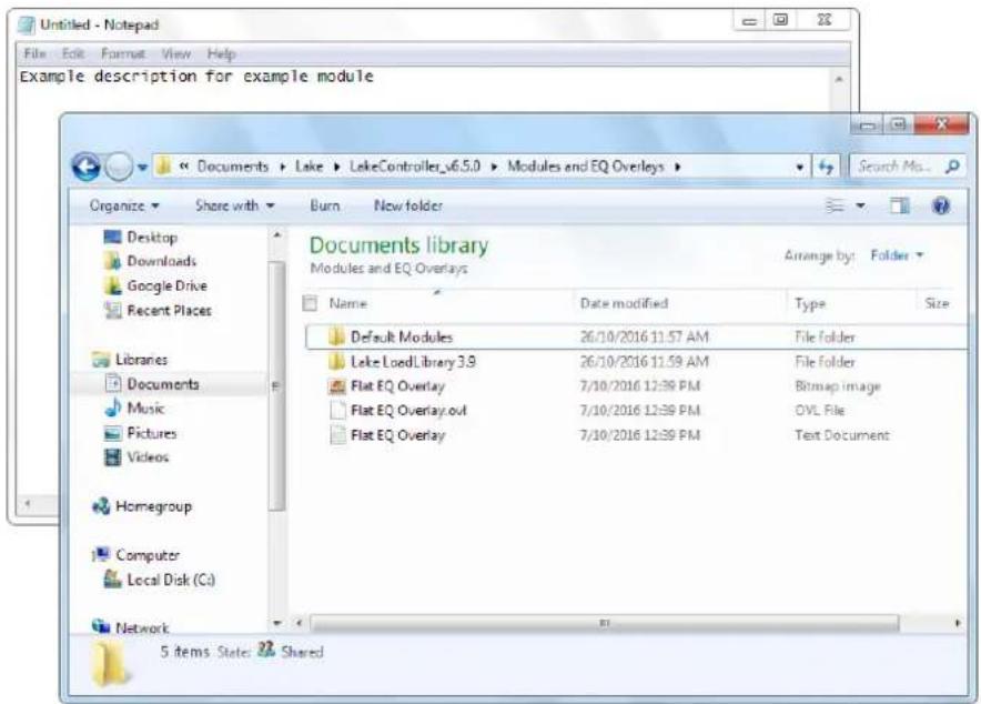
Figure 19-11: Storing a Module Help Text File
- Maximize the Lake Controller and navigate to MODULE STORE/RECALL.
- Select the Module file example from the scroll bar. The text you entered appears above the Module as shown in Figure 19-12.

Figure 19-12: Module Help Text
Module descriptions can be modified by editing the text file, or removed by deleting the text file. A shortcut to the data/user folder is available at:
START > PROGRAMS > LAKE CONTROLLER > LAKE CONTROLLER USER DATA FILES.

Folder descriptions can also be created by placing a text file with the same name as the folder in the same directory as the folder.
19.4 Designer Worksheets
19.4.1 Overview
The Designer Worksheets provide the ability to quickly view and edit the majority of data for a Lake device via a spreadsheet style interface.
Designer worksheets are available only in Designer Mode, via the I/O CONFIG & Worksheets button.
To access the Designer Worksheets, perform the following steps:
- From HOME, tap MODULES.
- Select a Module in the work area.
- Tap I/O CONFIG & WORKSHEETS.
The following screen tabs are available for loudspeaker Modules in Designer Mode.

Figure 19-13: Designer Worksheets for Contour Modules
The following screen tabs are available for Mesa EQ Modules in Designer Mode.

Figure 19-14: Designer Worksheets for Mesa EQ Modules
- Tap LEVELS - DESIGN.
A screen similar to that shown below will be displayed.
| I/O Config Xover/Aux - Design Levels - Design PEQ - Design GEQ - Design Lake | |||||||||||
| Module | A - CL3Way | B - CL3Way | |||||||||
| Channel Type | Input Mix | Output | Output | Output | Input Mix | Output | Output | Output | Input Mix | Outp | |
| Channel | n/a | 1 | 2 | 3 | n/a | 4 | 5 | 6 | n/a | ||
| Channel Label | Input | Low | Mid | Hi | Input | Low | Mid | Hi | Input | Lo | |
| Polanty | Polanty (+/-) | + | + | + | + | + | + | + | + | + | |
| Lock Polanty? (Y/M) | n/a | N | N | N | n/a | N | N | N | n/a | ||
| Gain | Factory Gain (dB) | 0.00 | 0.00 | 0.00 | 0.00 | 0.00 | 0.00 | 0.00 | 0.00 | 0.00 | 0.€ |
| User Gain (dB) | 0.00 | 0.00 | 0.00 | 0.00 | 0.00 | 0.00 | 0.00 | 0.00 | 0.00 | 0.€ | |
| Delay | Factory Delay (ms) | 0.00 | 0.00 | 0.00 | 0.00 | 0.00 | 0.00 | 0.00 | 0.00 | 0.00 | 0.€ |
| User Delay (ms) | 0.00 | 0.00 | 0.00 | 0.00 | 0.00 | 0.00 | 0.00 | 0.00 | 0.00 | 0.€ | |
| MaxRMS Limiter | Factory MaxRMS Level(dBu) | n/a | 4.00 | 4.00 | 4.00 | n/a | 4.00 | 4.00 | 4.00 | n/a | 4.€ |
| User MaxRMS Level(dB) | n/a | 20.00 | 20.00 | 20.00 | n/a | 20.00 | 20.00 | 20.00 | n/a | 20.€ | |
| User | |||||||||||
Figure 19-15: Levels-Design Worksheet
19.4.2 Worksheet Navigation and Data Entry
To navigate to the worksheets, select one of the Design tabs at the top of the screen.
19.4.2.1 External Keyboard Entry
For fast data entry via the Designer Worksheet, an external keyboard should be attached. Use the arrow keys to navigate around the cells of the worksheet, and enter values and data using the keyboard. The data of the current cell will be verified and updated when you move to the next cell.
Cut/Copy/Paste functionality between cells in the worksheet is available using the following standard keyboard shortcuts.
▶ Ctrl+X Cut ▶ Ctrl+C Copy ▶ Ctrl+V Paste
19.4.2.2 On-screen Keyboard Entry
If a keyboard is not attached, you may select a cell using the touch screen:
▶ A single tap selects the cell.
▶ A double tap displays the on-screen keyboard to allow you to enter the data.

Cell Cut/Copy/Paste functionality is not available without an external keyboard attached.
19.4.3 Xover/Aux: Design (Loudspeaker Modules Only)
The XOVER/AUX screens provide access to HPF and LPF frequencies and types (including crossovers) along with output EQ filters and types. The abbreviated codes for this data are listed here with descriptions.
19.4.3.1 HPF and LPF Types
The same HPF/LPF/Crossover types are allowed via data entry as are allowed via the HPF/LPF/Crossover scroll bars on the XOVER page. The following HPF/LPF types are available for the lowest output HPF and highest output LPF.
| BESSEL BUTTERWORTH LINKWITZ-RILEY | ||
| BE6 BU6 - | ||
| BE12 BU12 | LR12 | |
| BE18 BU18 | - | |
| BE24 | BU24 | LR24 |
Table 19-2: HPF/LPF Types
19.4.3.2 Classic Crossover Types
The following HPF/LPF types are allowed for crossover points only (all HPF/LPF fields except for the HPF on the lowest output channel, and the LPF on the highest output channel for the Module).
| BESSEL BUTTERWORTH LINKWITZ-RILEY | ||
| BE6 BU6 - | ||
| BE12 BU12 LR12 | ||
| BE18 BU18 - | ||
| BE24 BU24 LR24 | ||
| BE30 BU30 - | ||
| BE36 BU36 | LR36 | |
| BE42 BU42 | - | |
| BE48 BU48 | LR48 | |
Table 19-3: Classic Crossover Types
19.4.3.3 Linear Phase Crossover Types
The following HPF/LPF types are allowed for Linear Phase 2-Way and 3-Way Module crossover points only (i.e. not the HPF on the lowest output channel or the LPF on the highest output channel for the Module).
Table 19-4: Linear Phase Crossover Types

Linear phase crossovers require both sides of the crossover point to be the same crossover type. Therefore if one side of the crossover is changed, the other side will change automatically.
19.4.3.4 Linear Phase Alignment Delay
Unlike most values in the worksheet, ALIGNMENT DELAY is a Module-based value, not a channel-based value. Therefore, when ALIGNMENT DELAY is changed for any channel, all other channels of that Module will be updated automatically.
Linear Phase 2-Way and 3-Way Modules provide six settings: 1.25 ms, 2.5 ms, 5 ms, 10 ms, 20 ms, 40 ms.
Linear Phase Brick Wall 4-Way Modules provide four settings: 3.15 ms, 6.29 ms, 12.58 ms, 25.17 ms.
19.4.3.5 Output EQ Types
Table 19-5 shows the abbreviations for adding output EQ filters via the XOVER - DESIGN worksheet, along with associated default values.
| EQ TYPE | DESCRIPTION | GAIN | FREQUENCY | BANDWIDTH |
| LS | Low Shelf | 0 dB | 125 Hz | 1.9 |
| BP | Band-pass (Parametric) | 0 dB 500 Hz 0.33 | ||
| AP All Pass | 2nd Order | 800 Hz 0.33 | ||
| HS | High Shelf | 0 dB | 8 kHz | 1.9 |
Table 19-5: Output EQ Types
19.4.3.6 FIR Import/Export (XP Modules Only)
The XP module offers FIR import/export. On the Output FIR row, tap the (Menu bar) cell in the output row and then the FIR IMPORT/EXPORT button on the menu will be enabled. Import or export the FIR file. The FIR file requires a .fir file extension with one FIR tap on each row, up to 384 taps can be imported.
19.4.4 HPF/LPF - Design (Mesa EQ Only)
Crossovers, EQ, and All Pass filters are not available on the Mesa EQ HPF/LPF - DESIGN screen. The same HPF/LPF types are available for Mesa EQ as listed in Table 19-2.
19.4.5 Levels - Design
The data on the LEVELS - DESIGN worksheet is entered by typing the appropriate numerical value into a cell on the worksheet. An error message will be displayed if the value is invalid or incorrect.
To set polarity through the LEVELS - DESIGN worksheet, enter either + (positive) or - (negative) in the polarity field. The polarity of each output can be independently locked using the LOCK POLARITY? field, which is only available via this worksheet.
To lock polarity of an output, change the value in the associated LOCK POLARITY? field to Y. The example Module in Figure 19-16 has the polarity of all channels locked except for the input and lowest output.
| Output Channel No. | n/a | 1 | 2 | 3 | 4 | |
| Channel Label | Input | Low | Low Mid | Hi Mid | Hi | |
| Polarity | Polarity (+/-) | + | + | - | + | - |
| Lock Polarity? (Y/N) | n/a | N | Y | Y | Y |
Figure 19-16: Locking Polarity
When the Module is locked, the worksheet will appear as shown in Figure 19-17. In this example, output polarity for channels 2, 3, and 4 will be locked even in Designer Mode.
| Output Channel No. | n/a | 1 | 2 | 3 | 4 | |
| Channel Label | Input | Low | Low Mid | Hi Mid | Hi | |
| Polarity | Polarity (*/-) | + | + | Locked | Locked | Locked |
| Lock Polarity? (Y/N) | n/a | N | Y | Y | Y |
Figure 19-17: Polarity Locked
Designer worksheets are not available in User Mode, and in the example shown in Figure 19-17, only the input and low output polarity buttons will be visible.
19.4.6 PEQ - Design
The PEQ-DESIGN worksheet displays the details for each PEQ overlay for the selected Lake device. Table 19-6 shows the available PEQ type abbreviations, descriptions, and default values.
| EQ TYPE | DESCRIPTION | GAIN | FREQUENCY | BANDWIDTH |
| LS | Low Shelf | 0 dB | 125 Hz | 1.9 |
| BP | Band-pass (Parametric) | 0 dB | 500 Hz | 0.33 |
| ME | Mesa Filter | 0 dB | 830 Hz | 0.33 |
| 0 dB | 1.2 kHz | 0.33 | ||
| HS | High Shelf | 0 dB | 8 kHz | 1.9 |
Table 19-6: PEQ Types

The extra fields for the Mesa filter can only be edited when a Mesa filter type is entered.
19.4.7 GEQ - Design
The GEQ-DESIGN worksheet displays the details for each GEQ overlay for the selected Lake device, including the gain value of each GEQ filter and the bypassed/inserted status of each filter and each overlay.
19.4.8 BLEQ - Design
The BLEQ-DESIGN worksheet displays the details for each BLEQ overlay for the selected Lake device. Table 19-7 shows the available BLEQ type abbreviations, descriptions, and default values.
| EQ TYPE | DESCRIPTION | GAIN | FREQUENCY | BANDWIDTH |
| LS | Low Shelf | 0 dB | 160 Hz | 2.0 |
| ME Mesa Filter | 0 dB 160 Hz 2.0 | |||
| 0 dB | 1.6 kHz | 2.0 | ||
| HS | High Shelf | 0 dB | 1.6 kHz | 2.0 |
Table 19-7: BLEQ Types

The extra fields for the Mesa filter can only be edited when a Mesa filter type is selected.
19.4.9 Locked Modules/Hidden/View Only Data
If data on a Module has been hidden or set to view only, and the Module has been locked, the associated data will either be view only on the worksheets (View Only data) or will be replaced with the word LOCKED (Hidden data).
20. Lake-enabled Amplifier Reference
This chapter describes information specific to using the Lake Controller with Lake-enabled amplifiers including PLM, PLM+ and D Series devices. For further details on each product, please refer to the relevant Operation Manual.
20.1 Signal Flow
The diagrams below depict the audio signal flow for Lake-enabled amplifiers.
![graph TD A["*INPUTS\nDante Receivers 1-8\nAES 1-4\nAnalog 1-4"] --> B["Input Routers 1-4*\nWITH INPUT MUTES"] B --> C["Input Mixer A\nLake Contour Module A"] B --> D["Input Mixer B\nLake Contour Module B"] B --> E["Input Mixer C*\nLake Contour Module C*"] B --> F["Input Mixer D\nLake Contour Module…](/content/2026/07/1419186/images/58e1cb91ee556496e952df26009c1d5a4be27adac36ce4d84f6c01121126f24e.jpg)
* PLM Series is limited to 2 Inputs, 2 Outputs and 2 Contour Modules. ^ Not applicable for PLM Series.
Figure 20-1: Amplifier Signal Flow
The signal flow within the Lake Contour Module is shown below.
![graph LR A["Gain Phase Rev Mute"] --> B["EQ"] B --> C["Delay"] C --> D["Xover"] D --> E["EQ"] E --> F["Gain/Delay Phase Rev Mute"] F --> G["LimiterMax RMS / Peak"] H["MODULE INPUT"] --> A I["MODULE OUTPUT"] --> E](/content/2026/07/1419186/images/89109aef2d91b8961f7fa6d1b191fc52067b4a962cb742fec8de34e1f7ef43f3.jpg)
Figure 20-2: Lake Contour Module Signal Flow
20.2 Monitoring & Control
Many basic operating parameters are available in both the Lake Controller software and on the front panel (except for D Series). These include, for example, gain adjustment, monitoring of output levels and temperatures, and power control.
Basic per-channel operating parameters and gain adjustments are presented in the Status tab, with certain adjustments and power control accessed via the Control tab. The History and Events tabs provide both real-time log data and a graphical representation of the amplifier's performance.
20.3 Lake LoadLibrary™
In addition to the standard loudspeaker preset Module files, the Lake LoadLibrary includes a set of enhanced files specifically for use with Lake-enabled amplifiers. These Module files provide parameter settings for Amplifier Gain and ISVPL™ limiter.
Some Lake LoadLibrary loudspeaker types may include electrical characteristics data for the associated loudspeaker. The data set relating to the loudspeaker's electrical characteristics is used to enable load verification (LoadSmart™) to be performed. This data set is termed a Fingerprint. When a Lake-enabled amplifier loudspeaker type is recalled, its Fingerprint load characteristics are included. These load characteristics are stored in a file with a ".mdl" suffix and are recalled simultaneously with the Module file.
Lake LoadLibrary Modules can be recalled into any Lake-enabled device. Certain data such as ISVPL, Amplifier Gain and Fingerprint information is ignored when a Module is recalled into a device that does not support these features.

Custom RPM parameters are stored in System files and Frame Presets; these settings are not stored in Module files.
20.4 LoadSmart™
LoadSmart is Lab.gruppen's exclusive system for verifying the load connected to each output channel of the amplifier. LoadSmart is set up and run from the LoadSmart Tab. The number of each type of cabinet that should be connected to each power channel can be specified, along with cable lengths, resistance, etc. LoadSmart evaluates the load characteristics on each power output channel and either confirms them as correct or reports if they are exhibiting anomalies.
LoadSmart is available when a Module with an associated Fingerprint file is loaded; check the Lake LoadLibrary release notes to confirm which speaker presets have an associated Fingerprint file. Please refer to section 9.9 for further details.
20.5 Navigation
The AMPLIFIER EVENTS & CONTROL functionality, when used with Lake-enabled amplifiers, provides additional module-level information including STATUS, HISTORY and LOADSMART information. MODULE VIEW and GLOBAL VIEW. Each has further tabbed views.

Figure 20-3: Events & Control Module View Tabs
20.5.1 Accessing Module View
Module View can be accessed by three different methods.
- Tap HOME [F1] then tap a Module icon. Ensure LEVELS is selected, then tap AMPLIFIER EVENTS & CTRL (located below the first output fader).
- Tap HOME [F1] then tap MODULES [F3]. Select a Module, tap I/O CONFIG [F4] then tap EVENTS & CTRL [F7].
- Tap HOME [F1] then tap the ALL page tab. Tap a Module icon to access AMPLIFIER EVENTS & CTRL.
20.5.2 Accessing Global View
To access Global View:
- Navigate to the ALL page then tap GLOBAL EVENTS & CTRL [F9]
![graph LR A["Events"] --> B["Control"]](/content/2026/07/1419186/images/f489e10e67ecd2ae9eaa135b2b88f543f9526172bc22116d38d9aa497e620c51.jpg)
Figure 20-4: Events & Control Global View Tabs
20.6 Status Tab
The STATUS display is selected by tapping the STATUS tab in MODULE VIEW.
Channel strips display data relating to each power output section assigned to the selected Module.
The channels are presented in Module output order (e.g., low, mid, high). If a Module output is assigned to more than one power output channel, then this is displayed accordingly (e.g., low, low, mid, high).
The amplifier's meters are reproduced as vertical bar graphs. Each channel strip provides an attenuation fader, phase reverse button, and mute button. Additional identity and status information concerning the output channel and connected loads is shown below in two data blocks. To the right of the channel strips, a column of control buttons provides options for displaying and enabling the mute and polarity buttons on individual channels.

Figure 20-5: Status Tab Speaker and Power Output Channel Status
20.6.1 Attenuation

The virtual fader permits adjustment of the channel's attenuation, from 0 dB (fader fully open) to -∞ dB (fader closed). Moving this fader has the same effect as adjusting attenuation on the front panel in Menu Mode, via MENU > ATTENUATION.
The attenuation value may also be set by tapping the numeric display at the top of the fader. A numeric keypad opens allowing an absolute value to be entered.
20.6.2 Mute 2
The large mute button below the meter display activates the mute function for the power output channel. The button changes color to red when the mute is applied, and the legend changes from UNMUTED to MUTE. This function is equivalent to muting via the front panel for PLM and PLM+ Series devices.
20.6.3 Phase Reverse ③
A phase reverse button is provided which inverts the audio signal within the channel power output stage. The button is blue and normally shows the legend +Φ; when applied it turns red and shows -Φ. Note that this is an additional phase reversal at a later stage in the signal chain from the Lake Processing Modules, and does not have an equivalent control via front panel operation, or elsewhere in the Lake Controller software.
20.6.4 Meters 4
Four vertical bar graph meters are depicted for each channel. These display output voltage (V), current (I) and power (P), along with the amount of gain reduction applied by combined action of the various limiters and protection circuitry (L). The meters correspond to the four bar graph meters on the PLM or PLM+ Series front panel display in METER MODE, MODULE VIEW. Clip indicators for, respectively, voltage and current are located directly above the voltage and current meter. Clip behavior is shown by a red light, using a fast update rate to correctly indicate ballistics.
Two numerical displays are above the meter block. The top display switches mode dynamically to show the parameter closest to clipping at the moment: voltage (V), current (I) or power (P). The bottom display shows the current value of the Limiter meter.
20.6.5 Speaker Data Block 5
The display block below the meter section provides user feedback about the loudspeaker connected to each power output channel.
▶ SPEAKER - The name shown here corresponds to that of the Module outputs and usually describes the frequency band (e.g. Low, Mid, High) that a particular power output channel addresses.

For Modules with two or more identical output channel names, the channel number will be appended.
STATUS - OK is displayed when all load detection and monitoring functions report that the load attached to the power output channel is normal. If output conditions are such that a fault or warning state arises, a message will be displayed here advising the nature of the problem. Please refer to the associated Operation Manual for a list of fault/warning messages.
▶ LoadPilot status (PLM+ and D Series only). LoadPilot is configured via the separate CAFÉ software application. Not available for PLM Series amplifiers.
20.6.6 Power Output Data Block 6
The bottom display block provides user feedback about the performance of the device. The information is (from top):
▶ AMPLIFIER - Confirms Frame label and channel number. The channel number corresponds to the power output channel. The Frame name and number are separated by a colon. STATUS - OK is displayed during normal operation, when no faults, warnings or clipping is occurring. If an amplifier-related fault or warning state arises, a message is displayed here indicating the problem. TPSU - Provides the temperature of the power supply. The temperature is expressed as a percentage of the maximum safe value. TCH - Provides the temperature of the particular channel's output stage, displayed as a percentage of the maximum safe value. ▶ TAMP - Whichever of TPSU or TCH is closer to the maximum temperature allowed is also displayed on a horizontal bar graph.
20.6.7 Mute and Polarity Enable
Controls to the right of the channel strips enable and disable the MUTE and POLARITY functions on a global basis. When MUTE is enabled (default), the mute buttons are active. When MUTE is disabled, the mute status cannot be changed.
Polarity control allows three states:
▶ HIDDEN (default) removes the polarity buttons from the channel strips. ▶ VISIBLE displays the polarity buttons but they are disabled. ▶ ENABLED activates the buttons and allows a change of state.

The Mute and Polarity enable controls are global for all Modules currently in the work area. Controls are reset to defaults at the start of each new session.
20.7 History Tab
A log of various optional parameters is maintained within the device. Samples are taken every two minutes. The last 120 samples (i.e. the last 4 hours of operation) may be viewed Graphically on the HISTORY tab.

Figure 20-6: Module History Tab
20.7.1 Select Curve
The HISTORY tab displays a graph of several operational parameters against time. The vertical (Y-) axis is in arbitrary units and is scaled from 0 to 100%; the horizontal (X-) axis is effectively 'time', but actually shows the previous 120 samples taken at 2 minute intervals.
The parameter to be displayed is selected by tapping on one of the buttons in the SELECT CURVE box below the graph. The options are:
- COMBINED HEADROOM – This curve is constructed from all the individual parameters listed below, and shows the maximum value derived from all of them at each sample time. FRAME PSU TEMP – Displays the temperature of the PSU relative to its maximum safe level.
- AMP CHANNEL TEMP – Displays the temperature of the power output channel devices relative to their maximum safe level.
- AMP OUTPUT CURRENT – Displays the channel's output current relative to its maximum safe value. (This is the value at which the CPL becomes active.)
- AMP OUTPUT VOLTAGE – Displays the power output channel's voltage relative to the voltage permissible, regardless of ISVPL setting. ▶ TOTAL OUTPUT POWER – Displays the total output power (sum of all channels in that Frame) relative to the maximum rated power.
- AMP OUTPUT POWER – Displays the power output channel's power relative to the maximum rated power.
- MAINS CURRENT – (PLM 20000Q, PLM+ and D Series Only) Displays the mains current as a percentage of the maximum current.
- MAINS VOLTAGE – (PLM 20000Q, PLM+ and D Series Only) Displays the mains voltage as an actual value in volts.
20.7.2 Select Dimension
The MIN, PEAK and AVERAGE buttons in the SELECT DIMENSION box determine whether the data displayed on the graph is the log of minimum, peak or average values for the displayed parameter.
MIN is only active for the Mains Voltage parameter, and displays the minimum Mains Voltage levels at intervals during the sample period (PLM 20000Q, PLM+ and D Series Only).
PEAK displays the highest values attained by each parameter during the sample period.
AVERAGE displays the average of the values measured during the sample period.
20.7.3 Channels
The graph displays data for any selected power output channel assigned to the selected Module, or any combination of channels. The number of channel buttons that appear under SELECT CHANNEL/S depends on the Module configuration. The channel buttons display the associated Module channel labels; the curves on the graph are color coded, with a key color shown below each channel button.
The SELECT/DESELECT ALL button toggles states to either select or deselect all channels on the selected Module.

With a single channel selected, clicking the graph will display the time and sample number for that sample on the status line.

A white dot is displayed on the graphs if a power cycle of the Frame was performed during the sampling period.
20.8 Events Tab
The MODULE EVENTS tab shown in Figure 20-7 lists all faults and warnings occurring in the power output channels allocated to the selected Module.
The EVENT LOG displayed on this screen is the same as that displayed via GLOBAL EVENTS with filters applied to only display events relevant to the currently selected Module, power output channels assigned to that Module, and the Frame/s incorporating those channels. The tab is identical in format and function to the GLOBAL EVENTS tab. Please refer to section 20.12 for further details.

Figure 20-7: Module Events Tab
20.9 LoadSmart Tab
The LoadSmart page is selected by tapping the LoadSmart tab in Module view. LoadSmart loudspeaker verification is initiated from this tab. LoadSmart generates a test signal which is applied to the power output stage. Measurements are taken at the power output stage, and the results computed for the speaker type, using data from the Fingerprint. It is specified in the LoadLibrary documentation which SpeakerPresets have Fingerprint data.

The LoadSmart tab is disabled if fingerprint data is not present, and also when the Lake-enabled amplifier is in Standby mode.

Some LoadLibrary SpeakerPresets do not have associated Fingerprint data.
The LoadSmart tab allows editing of default cable data in the Fingerprint, including cable characteristics that are used in the calculation of the total cable resistance for each loudspeaker. The Lake Controller application combines this information with the known loudspeaker characteristics contained in the fingerprint to accurately verify the load and to confirm correct loudspeaker system operation.

Figure 20-8: LoadSmart Tab and Verification
20.9.1 Number of Cabinets
The number of loudspeaker cabinets connected in parallel to each channel is entered in the No. of Cabinets in Parallel field. LoadSmart uses this value for verification purposes. This data may also be entered via the PLM or PLM+ Series front panel. Please refer to the relevant Operation Manual for further information.

Number of Cabinets are not read from the SpeakerPreset.
20.9.2 Cable Resistance
The Cable Resistance field presents the total cable resistance that is configured for each power output channel. The fingerprint contains a default cable type that is recalled with the file. Tapping the CABLE RESISTANCE field opens the Cable Resistance Calculator where the individual cable parameters can be viewed and edited.
Changes made on the Cable Resistance Calculator are reflected in the Cable Resistance field.
20.9.2.1 Calculator
The Cable Resistance Calculator provides input fields for cable length, cable gauge, contact resistance and cable resistivity. The entered data fields give a calculated result for the total loudspeaker cable resistance in ohms. This value is reflected in the TOTAL CABLE RESISTANCE field for the selected power output channel in the upper table. The values for a specific cable's properties (resistivity, gauge, etc.) can be obtained from the cable manufacturer's data sheets.
20.9.2.2 Ambient Temperature
The load verification and monitoring system takes ambient temperature into account when checking the performance of the load. The ambient temperature for the system is entered in the GLOBAL CONTROL tab, accessed from the ALL view. Please refer to section 20.9 for further details.

The TEMPERATURE setting also affects the temperature presentation in LOAD RESULTS and STATUS.
20.9.3 Fingerprint Label
This field presents the label of a particular fingerprint as it was set when the fingerprint was created.
20.9.4 Verify
After all required cable data is entered, tap VERIFY to initiate LoadSmart verification. Tap YES to confirm. Load verification commences for all power output channels assigned to the selected Module. The channels are muted and a sequenced sweep is issued. After the verification procedure has been conducted, the LOAD RESULTS window appears.
Simultaneous load verification of all Lake-enabled amplifiers on the network can be initiated from the GLOBAL CONTROL tab. Please refer to section 20.9.

LoadSmart verification can be initiated from the PLM and PLM+ front panel, with a reduced set of results displayed on the front-panel LCD. Refer to the relevant Operation Manual for further info.

Figure 20-9: Load Verification Results
20.9.5 Settings
The set of buttons at the foot of the page allow the user to select the most convenient measurement units for the load verification system and cable resistance calculation. The options are:
▶ TEMPERATURE – °C or °F ▶ CABLE LENGTH – Meters or Feet
▶ CABLE GAUGE – AWG numbers or as mm² cross-section
20.9.6 LoadSmart Results
LOAD RESULTS reports the findings of the verification procedure. Results for each power output are displayed together with a summary in the ALL column.
20.9.6.1 Load Type Verification
The results shown in the Load type row of the table will be one of the following:
- CORRECT – The measured load characteristics closely match the values predicted from the load library data in combination with the total resistance calculation. UNCERTAIN – The measured load characteristics exhibit a degree of variance from the predicted values. A warning becomes active on the channel.
- WRONG – The measured characteristics differ widely from the predicted values; it is assumed that the load has malfunctioned or is of the wrong type. A fault is issued and the channel remains muted. A successful re-verification, power cycle, or placing the device into standby mode, will clear the fault and the mute state.
- NO MODEL – Fingerprint data is missing from the Module file selected.
- ABORTED – A power output channel was in a protective state during the load verification process (e.g. temperature fault).

The ALL column summarizes the NUMBER OF CABINETS verification result from each power output channel in the order VERIFIED > WRONG. e.g. 2/1 = two channels match, one does not.

If LOAD TYPE VERIFICATION fails, the power output channel will be muted to prevent speaker damage. A subsequent CORRECT or UNCERTAIN verification (or power cycle) resolves the mute.
20.9.6.2 Cabinet Count Verification
The results in the NUMBER OF CABINETS row will be one of the following:
- VERIFIED – The measured load impedance indicates the number of cabinets connected to this power output matches that configured.
- WRONG – The measured load impedance indicates either that the number of cabinets connected to this power output channel is incorrect.

If the correct number of cabinets is entered but the results returned are wrong it is possible to force settings by selecting FORCE TO CONFIGURED.
20.9.6.3 Voice Coil Temperature
The VOICE COIL TEMPERATURE row indicates the estimated loudspeaker voice coil temperature from the LoadSmart test results. This is calculated from the LoadSmart verification results and Fingerprint data.

The ALL column summarizes temperatures in the order Min/Average/Max. e.g. 20/23/25 = voice coil temperatures in range 20° C to 25° C, with an average value of 23° C.
20.10 Output Tab
The Module control page is selected by tapping the OUTPUT tab in Module view.
The Control tab displays data contained in the Module output DSP channel, and not the power channels. It is important to remember that AMPLIFIER GAIN and ISVPL data are stored within each Module DSP channel alongside other Lake Module data. Appropriate AMPLIFIER GAIN and ISVPL data are transferred to the respective power output channel/s when they are routed to the Module outputs.

Custom RPM configuration can result in power output channels having unique actual ISVPL values even though they are routed from the same DSP channel.
![Status History Events LoadSmart Output Power MODULE A: 3 - 12K44 - CL3way ALL Low Mid High Amplifier Gain (dB) 35.0 35.0 35.0 35.0 ISVPL Speaker Threshold (V) - 194.0 170.0 135.0 Actual ISVPL (V) Pwr1 [194.0] RPM Pwr3 [170.0] RPM Pwr4 [135.0] RPM Pwr2 [194.0] RPM ISVPL Profile - LF MF HF Amplifier C…](/content/2026/07/1419186/images/e9a10e97a29b28b0e50fde85f8cf5902cf09ce0ed1eb5a11bb4e65e0c8e90e6f.jpg)
Figure 20-10: Output Tab
20.10.1 Amplifier Gain
The amplifier gain parameter on the Output tab relates to the power output stage of the amplifier.
This gain is set per Module output channel, and it is part of Speaker Preset files created for Lake-enabled amplifiers. Any power output channel routed to a Module output will inherit the Amplifier Gain value specified for that Module output.
To change the amplifier gain for a channel, tap on the associated cell and enter a value via the pop-up numeric keypad. Entering a value in the ALL cell applies that value to all power output channels.
Amplifier gain may also be set via the front panel via MENU > MODULE > AMP GAIN on PLM and PLM+ devices only.
20.10.2 Inter-Sample Voltage Peak Limiter (ISVPL) Threshold
The ISVPL threshold information is displayed in the second row of the Control tab table.
Blue text indicates the desired value; white text within block parenthesis indicates the actual value for each power output. The actual value per power output channel can be affected by:
▶ The ISVPL Threshold
The maximum voltage a particular Lake-enabled amplifier can produce
▶ Rational Power Management (RPM) configuration (PLM+ and D Series only)

The maximum upper limit is 600 V, but is capped at the maximum allowed channel voltage for the specific model. In Bridge mode, double the normal maximum channel voltage is allowed. Please refer to the Product Operation Manual for additional information.
Module settings are cross compatible between models and the ISVPL threshold can be set to the voltage that a speaker may require. If the Module is recalled or copied to a device with a lower output voltage capability than the configured value, the actual value will be limited accordingly. When using a device with lower output voltage, a higher configured value can still be adjusted and stored.
The actual ISVPL is the resulting ISVPL (including RPM functionality for PLM+ and D Series). The actual ISVPL is displayed per Power channel (Pwr). Actual values read from the device are displayed in [brackets] and calculated values between |vertical lines|. The values are calculated for virtual, offline and standby frames.
These values correspond to the ISVPL settings adjusted on the PLM or PLM+ Series front panel via MENU > MODULE > LIMITERS > ISVPL. Threshold values may be adjusted on the front panel interface or on screen in the same manner as above.
AMPLIFIER GAIN and ISVPL are subject to limits set by the system designer. If you are unable to change a value, this may be due to restrictions set by the system designer for that parameter. See section 20.10.5.
20.10.2.1 Rational Power Management (PLM+ and D Series only)
Rational Power Management™ (RPM) is a unique Lab.gruppen feature that allows for flexible allocation of power across channels. It is available in two modes: Auto and Custom.
Auto RPM
The frame automatically allocates power per output channel according to the ISVPL settings in the speaker preset (Module file). Power that is unused by one output channel is available for use by another output channel provided the total limit for the amplifier model is not exceeded.
When RPM is active, 'RPM' text is displayed next to the Actual ISVPL values. When the specified ISVPL threshold is reached, 'RPM' is displayed green (see Figure 20-10); if the threshold is not reached 'RPM' is displayed yellow.
Custom RPM
An advanced custom power allocation scheme may be created using the CAFÉ software.
Selecting Custom RPM mode disables Auto RPM mode; please refer to the CAFÉ Operations Manual for further information on setting Custom RPM settings.
When RPM is active, RPM text is displayed next to the Actual ISVPL values.
20.10.3 ISVPL Profile
The ISVPL profile controls attack and release times of the ISVPL limiter along with the associated voltage clip behavior. There are six options available as shown and described in Figure 20-11.

Figure 20-11: ISVPL Profile Options
20.10.4 Amplifier Clip Level
The Amplifier Clip level is calculated from Amplifier Gain and ISVPL Speaker Threshold values. This figure represents the digital signal level from the Module output that will produce clipping or limiting at the power output channel. If no EQ or additional gain is applied in the Lake Processing Module, this figure also represents the digital input level at which clipping or limiting will be produced at the power output channel.

The ALL column parameter displays if all values for the parameter type are identical.
20.10.5 Amplifier Gain and ISVPL Level Limits
Designer Mode allows a system designer to set level limits for Amplifier Gain and ISVPL, and hide these parameters. This function is accessed from a button visible only in Designer Mode when both the Module and base configuration file are unlocked.
The LEVEL LIMITS button, located in the bottom right hand corner opens a new window where minimum and maximum levels can be set.
Level limits are stored as factory levels when a base configuration file is stored. Users loading a Module file employing this base configuration can only adjust parameters within the allowed range. If the maximum and minimum values are identical, the value is locked and hidden from view. For more information on Designer Mode, please refer to chapter 19.
20.11 Power
20.11.1 Power Control
POWER ON and STANDBY buttons are provided on the Power tab. These buttons can control the Frame (or multiple Frames in a Super Module configuration) containing any power output channels assigned to the Module, allowing the Frame/s to be set in Standby mode. A system-wide power control facility is available from the Control tab in Global View. Please refer to section 20.9 for further details.
20.11.2 Auto Power Down (PLM+ and D Series only)
If Auto Power Down is enabled (ON), the selected device will automatically go into standby mode after the defined number of minutes has been reached where the following criteria is met:
▶ No audio is passing on any Power output channel (signal must be below -60 dB). ▶ No user interaction via Lake Controller, Front Panel or 3rd Party Controllers
When the amplifier enters standby mode, it remembers that the expected power state is ON and thereby after a power cycle the frame will turn on again.

There is no Auto Power On feature, so the device will need to be turned on manually as required via the Lake Controller power control (either the per device or the global power), or from the front panel or 3rd Party power on command.
20.11.3 Adaptive Rail Control (D Series D10:4L, D20:4L & D40:4L only)
This feature allows selection between different Amplifier Rail profiles for improved energy efficiency, depending on application.
21. LM Series Reference and Operation
This chapter provides information specific to using the Lake Controller with LM Series devices. Please refer to the LM Series Operation Manual for further details on LM Series hardware and front panel functionality.
21.1 Pass-Thru Input Router Functionality
21.1.1 Overview
Although other types of Lake device provide the ability to pass audio directly from any input to any output, the LM Series devices provide the ability for the signal from any of the eight Input Routers to be patched directly to any other output. This allows the result of automatic fail-over input priority switching to be fed to the Module Input, or to any analog or digital output directly.
![graph TD A["Input Routers 1-4 WITH INPUT MUTES"] --> B["Input Mixer A"] A --> C["Input Mixer B"] B --> D["Gain Polarity / Mute"] B --> E["Gain Polarity / Mute"] C --> F["Gain Polarity / Mute"] D --> G["EQ"] E --> H["EQ"] F --> I["Delay"] G --> J["CROSSERS"] H --> J I --> J J --> K["EQ"] J --> L["EQ"…](/content/2026/07/1419186/images/d1693a872dbb20ecb79c0341121cf206b69a1509a706650f080e5e9a917fe3b6.jpg)
Figure 21-1: LM Series Signal Flow (Contour Mode)
![graph TD A["Input Routers 1-8 WITH INPUT SUTES"] --> B["Input Mixer A"] A --> C["Input Mixer B"] A --> D["Input Mixer C"] A --> E["Input Mixer D"] B --> F["Gain"] B --> G["EQ"] C --> H["Gain"] C --> I["EQ"] D --> J["Gain"] D --> K["EQ"] E --> L["Gain"] E --> M["EQ"] F --> N["Delay"] G --> O["Delay"]…](/content/2026/07/1419186/images/06cfdad9e8554c49cd084e3b8fd48ec073143efb58c8e08b936d61afd5fee996.jpg)
Figure 21-2: LM Series Signal Flow (Mesa Mode)
The signal from any of the eight input routers identified in Figure 21-1 and Figure 21-2 can be connected directly to any output. This is useful for various reasons, including audio signal conversion (e.g. from analog to digital) and for using the LM Series devices as a break-in box for Dante.
For example, Input Routers 1-4 could be configured to provide inputs to the processing modules, while input routers 7+8 could be configured to provide a stereo break-in for the Dante audio network. As it is the signal coming out of the input router that is connected to the outputs, rather than directly routing the input to the output, this provides the ability to fail-over from AES to Analog input before sending the signal to the output. This ensures that the receiving device has uninterrupted audio when fail-over from AES to analog occurs.

In Mesa Mode, the signal from all eight Input Routers is available for Input Mute and Module Input Mixer functionality. In Contour Mode, only Input Routers 1-4 provide this functionality; the signal from Input Routers 5-8 may be patched directly to the outputs.
21.1.2 Configuring Pass-Thru Input to Output via Input Router
To configure a pass-thru configuration via an input router:
- Navigate to HOME > MODULE > IO CONFIG > INPUT CONFIGURATION.
- Configure the input router with the relevant inputs and priorities as described in section 8.2.2.
To route the signal from the pass-thru input routers to a particular output:
- Navigate to HOME > MODULE > IO CONFIG > OUTPUT CONFIGURATION. Please refer to section 8.2.8 for further details.
- Tap the left arrow under the label 'Source'. The source will change to display 'Input Router Outputs' similar to that shown in Figure 21-3. This example has the source from Input Router 7 & 8 directly patched to AES4 (Out 7 & 8).

Figure 21-3: Output Configuration - Input Routers selected as Source
- Use the 'Destination' arrows to select the required output type, then select an available (blue) routing point to connect the signal from the Input Router to one or more outputs.

When connecting the Input Router signal directly to an output (bypassing the Module processing), the Input Router Mutes do not have any effect on the signal path. Please refer to the signal flow diagrams in Figure 21-1 and Figure 21-2.
21.2 GPIO Configuration
General Purpose Input/Output control (GPIO), allows external devices such as alarm systems to interface with the LM Series devices and control basic functions including mute, preset recall and standby/power control. The LM Series device can report the current state of protective mute and standby settings to an external system and also advise if a fault or warning occurs.
Please refer to section 8.2.3 on page 132 for further details, and also refer to the LM Series Operation Manual for GPIO technical reference and front panel functionality.
21.3 Remote Power Control & Event Logs
In addition to the common Lake Controller screens available for all Lake devices, the LM Series devices have additional Events & Control tabs available by navigating to EVENTS & CONTROL as described in section 21.3.1.
The Control tab provides the ability to remotely control the power/standby state of the LM Series device. Please refer to section 21.3.2 for further details.
The Event tab provides information on frame activity along with all faults and warnings that occur on the LM Series device. Please refer to section 21.3.7 for further details.
21.3.1 Navigation
The Events and Control screens are accessed as described in the following sections, depending on whether a Module, Super Module or Global View is required. Two tabs are displayed at the top of the screen in each case, distinguished by the words MODULE, SUPER MODULE or GLOBAL as shown in Figure 21-4, Figure 21-5 and Figure 21-6.
- Module View displays Events relating to the selected Module/Frame, and provides Power Control for that Frame only via the Control tab. Super Module View displays Events relating to all Modules/Frames that are assigned to the selected Super Module, and provides power control for those Frames. Global View displays Events relating to all devices in the current system configuration, and allows power control for all devices except MY8-LAKE.

Super Modules or Systems containing Lake-enabled amplifiers will display additional data relevant to the amplifiers only. Please refer to chapter 20 for further details.
21.3.1.1 Accessing Events and Control (Module View)
Events & Control Module View for LM Series devices can be accessed by three different methods.
- Tap HOME [F1] then tap a Module icon. Ensure LEVELS is selected, then tap EVENTS & CONTROL (located below the first output fader).
- Tap HOME [F1] then tap MODULES [F3]. Select a Module, tap I/O CONFIG [F4] then tap EVENTS & CONTROL [F7].
- Tap HOME [F1] then tap the ALL page tab. Tap a Module icon to directly access EVENTS & CONTROL.

Figure 21-4: LM Series Module Events & Control Tabs
21.3.1.2 Accessing Events & Control (Super Module View)
Events & Control Super Module View for LM Series devices can be accessed by three different methods.
- Tap HOME [F1] then tap a Super Module icon. Ensure LEVELS is selected, then tap EVENTS & CONTROL (located below the first output fader).
- Tap HOME [F1] then tap MODULES [F3]. Select a Super Module, tap SM ROUTING [F4] then tap EVENTS & CONTROL [F8].
- Tap HOME [F1] then tap the ALL page tab.
- Tap a Super Module icon to directly access EVENTS & CONTROL.

Figure 21-5: LM Series Super Module Events & Control Tabs
21.3.1.3 Accessing Events & Control (Global View)
To access Events & Control Global View:
- Navigate to the ALL page
- Tap GLOBAL INFO [F9]
- Tap EVENTS & CONTROL [F8]

Figure 21-6: Global Events and Control Tabs
22. MY8-LAKE Reference and Operation
This chapter provides information specific to using the Lake Controller with MY8-LAKE devices. Please refer to the MY8-LAKE Operation Manual for further details on MY8-LAKE hardware.
22.1 Signal Flow
The diagrams below depict the audio signal flow configurations available for the MY8-LAKE card. Please refer to the section 8.2.14 for details on how to change the audio processing configuration via the Lake Controller software.
22.1.1 Mesa Configuration Signal Flow Diagram
The MY8-LAKE defaults to an 8x8 system equalizer configuration known as Mesa mode. This configuration provides eight discrete channels of audio processing as shown below.
![graph TD A["MYB-LAKE INPUTS"] --> B["Input Routers 1-8 WITH INPUT MUTES"] B --> C["Input Mixer A"] B --> D["Input Mixer B"] B --> E["Input Mixer C"] B --> F["Input Mixer D"] B --> G["Input Mixer E"] B --> H["Input Mixer F"] B --> I["Input Mixer G"] B --> J["Input Mixer H"] C --> K["Gain EQ Delay HPF…](/content/2026/07/1419186/images/f040c85b202135761dce043faa1b9f787c35a4dadf26158400855c2185e2a74d.jpg)
Figure 22-1: MY8-LAKE Mesa Configuration Signal Flow Diagram
22.1.2 Contour Configuration Signal Flow Diagram
In loudspeaker processor configuration (Contour mode), the MY8-LAKE provides a 4x12 matrix of loudspeaker processing Modules as shown in the diagram below.
![graph TD A["MY8-LAKE INPUTS"] --> B["Input Routers 1-4 WITH INPUT MUTES"] A --> C["Input Routers 5-8 NO MUTES"] B --> D["Input Mixer A"] B --> E["Input Mixer B"] B --> F["Input Mixer C"] B --> G["Input Mixer D"] D --> H["Gain Polarity / Mute"] E --> I["Gain Polarity / Mute"] F --> J["Gain Polarity /…](/content/2026/07/1419186/images/dbe46f133e5f0fe3c13a30f42d2f2ce599d87fc161ddfc18d22c8fb129178b8a.jpg)
Figure 22-2: MY8-LAKE Contour Configuration Signal Flow Diagram
22.1.3 Contour/Mesa Configuration Signal Flow Diagram
In hybrid mode (Contour/Mesa), the MY8-LAKE provides a 4x6 matrix of loudspeaker processing Modules and an 8x4 matrix of single channel EQ Modules as shown in the diagram below.
![graph TD A["MY8-LAKE INPUTS HOST 1,2,3,4,5,6,7,8 AES 1,2,3,4,5,6,7,8"] --> B["Input Routers 1-8 WITH INPUT MUTES"] B --> C["Input Mixer A"] B --> D["Input Mixer B"] B --> E["Input Mixer C"] B --> F["Input Mixer D"] B --> G["Input Mixer E"] B --> H["Input Mixer F"] C --> I["Gain Polarity / Mute"] D -…](/content/2026/07/1419186/images/75b299818c49f806b1d54bbb9cb8f64bd3bda7bb5c27fff6fc3e3d38ef67ff5d.jpg)
Figure 22-3: MY8-LAKE Contour/Mesa Configuration Signal Flow Diagram
22.2 Operation Mode
The MY8-LAKE device supports three modes for Host device recognition as shown in Figure 22-4. The default setting of MY8-AE96 provides full functionality.

Figure 22-4: Card ID Operation Mode for Host data recognition
After changing the operation mode, cycle the power on the MY8-LAKE device to complete the process.

The Operation Mode parameter is unaffected by the recall of a Module or System file, or by the resetting of a Frame to default Contour or Mesa configurations.
22.3 Host Analog Output Reference Configuration
To ensure that limiter levels in the LoadLibrary Module files remain compliant with the MY8-LAKE device, an additional option will be available via the I/O CONFIG entitled ANALOG OUTPUT REFERENCE.
Analog Output Reference provides limiter compensation options as shown in Figure 22-5.
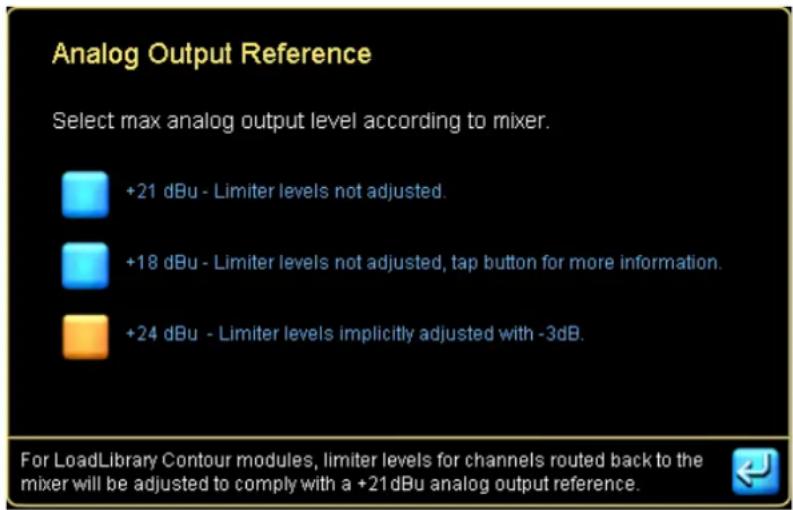
Figure 22-5: Analog Output Reference Options
The limiter compensation is active only on Host input channels (Host returns) from Contour Module outputs; outputs from Mesa Modules, or other output types will not have this compensation applied.
22.4 I/O Configuration View Mode Options
22.4.1 Simplified View (not yet implemented)
The MY8-LAKE provides a simplified I/O routing view by default for Mesa Mode that allows simple configuration of all input and output parameters. In Simplified View, the following functionality differs compared to normal Lake Controller operation:
The Digital Clock Configuration screen is disabled; the clock signal is locked by default to the same clock as the selected input source (i.e. Host Output or AES Input). Summary data is still displayed confirming the current automatic selection. The INPUT CONFIGURATION screen is disabled; the input type selected via the Input Toggle (Host Output or AES Input) is set as Priority 1 for the selected Module and corresponding input (i.e. Module A Input = Host Out 1 or AES In 1, Module B In = Host Out 2 + AES In 2, etc.) The Output Configuration screen is disabled; the Module is set to pass the processed signal to the corresponding Host Input and AES Output (i.e. Module A = Host In 1 + AES Out 1, Module B = Host In 2 + AES Out 2, etc.)
![graph LR A["Host Out Ch 1"] --> B["Input Gain"] B --> C["Input EQ"] C --> D["Input Delay"] D --> E["HPF/LPF"] E --> F["Output Levels"] F --> G["To AES Ch1 Output"] F --> H["To Host Ch1 Input"] I["AES Ch 1"] --> B](/content/2026/07/1419186/images/2c28f4e3adda6578af37e008528fb3a98dd8706a79dfa9c473990444fe107bde.jpg)
Figure 22-6: Signal Path for Mesa Module A in Simplified View
22.4.2 Classic View (All devices and configurations)
The standard fully functional Lake Controller I/O configuration view (Classic View) is also available for MY8-LAKE Mesa configurations. Classic View is the only option available when the MY8-LAKE is configured in Contour configuration or in the Contour/Mesa hybrid configuration.
This view provides all standard input and output configuration options that are applicable for the MY8-LAKE device as per normal Lake Controller operation; please refer to section 8.2 of this manual for further information.
22.4.3 Changing between Simplified View and Classic View
To change between Simplified View and Classic View:
- Tap Routing Mode at the bottom left of the screen
- Tap either the Simplified View or the Classic View button depending on the view required
Figure 22-7: MY8-LAKE Routing Mode Summary

When switching from Classic View to Simplified View, a router reset will be implemented to return the routing to the default Mesa Configuration routing.
23. Global Events and Control
23.1 Global Events Tab
The GLOBAL EVENTS tab provides an EVENT LOG listing warnings, faults, and user actions that have occurred in all devices on the network since the Lake Controller software was started. In addition, it contains events that can be read from each device's internal log covering four hours prior to starting the Lake Controller. Various filter options are available for displaying a user-definable subset of the log. The complete log is also continuously stored in 2-minute intervals in the \logs directory.

The data set for the most recent event is repeated in the separate horizontal pane at the bottom of the table.
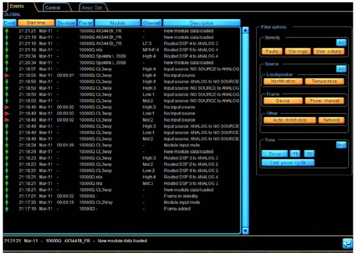
Figure 23-1: Global Events Logging Tab
23.1.1 Log Entries
Seven items of information per event are displayed in the log in tabular form, as follows:
▶ EVENT – Displays system faults or warning notifications. Icons shown below reference the source of the notification. Icons change color, from yellow (warning) to red (fault) to indicate severity.
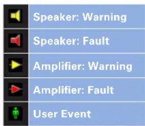
Figure 23-2: Events Tab Warning Icon Descriptions
▶ START TIME – Displays the system time and date at which the event occurred. - DURATION – Displays ACTIVE while the fault/warning is active. Once the fault/warning becomes inactive, the duration for which it was active is displayed. Once the event is cleared, its line of text in the log changes color from white to gray. FRAME – Identifies the Frame in which the fault/warning/event occurred by displaying the Frame label. If a Frame label has not been allocated, this field displays the default model name e.g. 10000Q. - MODULE – Displays the name of the Module in which the event occurred. This will be the default name (i.e. 3way, 2aux, etc.) if the Module has not been renamed. CHANNEL – Indicates the channel on which the event occurred. This column will be blank if the event was a Frame event – e.g. network failure, etc. DESCRIPTION – Displays a description of the event. A full list of the possible warning messages can be found in the relevant Operation Manual. For LoadSmart verifications, the distance from the Fingerprint will also be displayed.
23.1.2 Sorting Options
The default list order for the data displayed in the event log is chronological, with the most recent event at the bottom of the list. To sort the data by another column, tap the button at the top of the required column.
23.1.3 Filtering Options
The default event log records and displays all events for all Modules and Frames in the system. To reduce the number of log entries displayed, apply the filter options on the right of the screen. Regardless of filtering options currently selected, all events are recorded, and may be displayed later as required.
23.1.3.1 Severity
Recorded events are divided into three categories: FAULTS, WARNINGS and USER ACTIONS. Events in any or all of these categories may be displayed in the log by tapping the three buttons in the SEVERITY box. The ALL button restores the default state of all three categories being selected.
23.1.3.2 Source
Using buttons in the SOURCE box, events may also be filtered on the basis of which part of the system generated them. Any or all of six event sources may be selected, as follows:
▶ Loudspeaker Identification ▶ Loudspeaker Temperature ▶ Amplifier Device ▶ Amplifier Output ▶ Other: Audio distribution ▶ Other: Network
The ALL button restores the default state of all six categories being selected.
23.1.3.3 Time
It is possible to display only events which have occurred within a user-defined time interval, using the buttons in the TIME box. The options are:
- SINCE HH:MM – Tapping the HH and MM buttons opens a numeric keypad to allow a 'Start time' for displayed events to be entered. Tapping the SINCE button activates the option. LAST POWER CYCLE – Tapping this button causes the Event Log to only display events which have occurred since the last time the was powered up.
23.2 Global Control Tab
The GLOBAL CONTROL tab is the second of two tabs available in AMPLIFIER GLOBAL VIEW.
To access AMPLIFIER GLOBAL VIEW:
- Select the ALL page.
- Tap GLOBAL INFO.
- Tap the CONTROL tab
- Tap EVENTS & CONTROL [F8]

Figure 23-3: Global Control Tab
23.2.1 Global Power Control
Two buttons, ON and STANDBY, control the power status of all Lake-enabled devices (except MY8-LAKE) that are online and present in the current system configuration. A confirmation is required prior to changing this status across all devices.
Both buttons will be blue if a combination of statuses are present, or one button will be orange if all devices have the same status.
Status indicators to the right of the buttons show the total number of LM and PLM Series devices in the current system configuration that are ON, in STANDBY, or OFFLINE.

If the Global Power Control default sequence time is too quick, causing issues for the power distribution, this can be changed from the iC.ini file located in the Config folder of Documents. The setting is GLOBAL_POWER_DELAY and it is specified in ms.
23.2.2 Global Power Channel Mute Control
The Global Mute Control allows global control of all:
▶ Module Input Mutes ▶ Module Output Mutes ▶ Power Channels (Lake-enabled amplifiers only).
ALL MUTED and ALL UNMUTED indicate and control the specific mute. A confirmation is required prior to changing this status across all frames.
Both buttons will be blue if a combination of statuses are present for the specific mute, or one button will be orange if all devices have the same status.
Status indicators to the right of the buttons show the total number in the current system configuration that are MUTED or UNMUTED.
23.2.3 Global Temperature
The current ambient temperature (the temperature of the air surrounding the cabinets) may be entered on this tab. Tapping on the blue button in the AMBIENT TEMPERATURE box opens a numeric keypad for the purpose.
The temperature value is transferred to the LOADSmart Table on the MODULE LOADSmart Tab and used for load verification and monitoring procedures. Buttons allow selection of temperature display in degrees CELSIUS or FAHRENHEIT.
23.2.4 Global LoadSmart
The GLOBAL LOAD CONTROL VERIFY button initiates the system-wide load verification of all Frames.
23.2.5 Global Dual Redundancy Control
Two buttons, ON and OFF, control the Dual Redundancy network status of all devices that are online and present in the current system configuration (not applicable to MY8-LAKE). A confirmation is required prior to changing this status across all devices.
Both buttons will be blue if a combination of status are present, or one button will be orange if all devices have the same status.
Status indicators summarize the number of online devices in the current system configuration that have this status set to ON or OFF.

The power must be cycled on the device for this parameter change to complete. (i.e. Disconnect or turn off mains power then reconnect or turn on mains power).
Please refer to section 8.2.10.5 for further information regarding Dual Redundancy.
23.2.6 Global Dante Enabled Control
Two buttons, ON and OFF, control the Dante Enabled status of all devices that are online and present in the current system configuration (not applicable for MY8-LAKE). A confirmation is required prior to changing this status across all devices.
Both buttons will be blue if a combination of status are present, or one button will be orange if all devices have the same status. Status indicators summarize the number of online devices in the current system configuration that have this status set to ON or OFF.
Two additional buttons, 48 kHz and 96 kHz control the Dante sample rate for all Dante-enabled devices in the current system configuration.
One additional button, "Copy Frame Label", will copy all unique Frame Labels in the system and have these as Dante Device Name for all supported devices. This feature is also available per device in the Dante Configuration menu.
If a Frame Label is used by 2 or more devices, that Frame Label will not be used at all, and if a Dante Device Name already is used by another device not included in the system but on the Dante Network, this will also be skipped. After the operation, a Result report will be displayed.
23.2.7 Global Dante Transmit Enabled Control
Two buttons, ON and OFF, control the Dante Transmit Enabled status of all devices that are online and present in the current system configuration (not applicable for MY8-LAKE). A confirmation is required prior to changing this status across all devices.
Both buttons will be blue if a combination of status are present, or one button will be orange if all devices have the same status.
23.2.8 Global AES67 Enable Control (PLM+ and D Series only)
Two buttons, ON and OFF, control the AES mode on all supported devices present in the system configuration. Unsupported devices are listed in the n/a counter. All devices with AES67 mode enabled are listed under ON, and all devices with AES67 mode disabled are listed under OFF. Since devices are required to re-start when AES67 mode is changed, during the re-start devices will be listed under Pending.
23.2.9 Global Auto Power Down Control (PLM+ and D Series only)
Two buttons, ON and OFF and additional status information describe how Auto Power Down is configured for the devices in the current system configuration.
If Auto Power Down is enabled (ON), the selected device will automatically go into standby mode after the defines number of minutes has been reached where the following criteria is met:
▶No audio is passing

There is no Auto Power On feature, so the device will need to be turned on manually as required.
▶No user interaction via Lake Controller ▶No user interaction via Front Panel
When the amplifier enters standby mode, it remembers that the expected power state is ON and thereby after a power cycle the frame will turn on again.
23.2.10 Show Global Input Router Priority Control
This enables a button labeled "Prio" at the top right of the Lake Controller (just left of the minimize button). Tapping this button provides additional options to control all input routers in the system.
There is also an option to exclude LM devices in Mesa mode and all their input routers. This option to exclude LM could be used when there are LM Mesa mode devices used as signal transmitters and there is no need to control them.
See more information in section 4.2.4 "Global Input Router Priority Control".
23.2.11 Show Global Status Indicator
This turns on or off an indicator that appears in the bottom-right corner in any view if a Module goes offline, or if there is a fault/warning present. Faults will be represented with a red light, and warnings with a yellow light.
It is possible to click on the bottom right indicator when present and that will open up the Global Event log where, in many cases, it is possible to see why the light is on. This feature was previously available under ICON CONTROL.
23.2.12 Global IP Configuration
Two buttons, Auto and DHCP, make it possible to globally configure all devices in the system to either Auto (Zero Config) or DHCP/Auto IP Configuration. These are the same options as available from the I/O CONFIG Technical Data menu. There is no option to globally configure Fixed IP settings.
There is also a status counter summarizing what is currently configured in the system.
23.3 Array Opt (XP Modules only)
23.3.1 System Information
The Global Array Optimization tab offers an overview of the complete system for all outputs that have Array Optimization Capable and if an Array Optimization is present or not. This view will also indicate if there is any inconsistency. If anything looks interesting, press the cell and the Frame and Module label will be displayed to help with any troubleshooting.
23.3.2 Array Optimization Control
From this view it is possible to:
▶ "Insert ALL" Array Optimization ▶ "Bypass ALL" Array Optimization ▶ "Clear ALL" Array Optimization
This can only be controlled on a complete system level, and it is not possible to control it on a Module level. These controls will act on all XP modules in the system that has Array Optimization Capable enabled. Array Optimization Capable/Not Capable is controlled from the Array Opt button in the XP Signal flow on I/O CONFIG view.
The Array Optimization settings are:
▶ Stored in a System file, and will be recalled with a System Recall, Frame Replace, etc. - Not stored in a Module file, and will not be recalled on Module recall, Copy/Paste, etc.
While the Array Optimization is bypassed, if there is a Bypassed latency configured, this will be applied to the signal. The bypass latency is stored in the module file, and is locked if the module is locked.
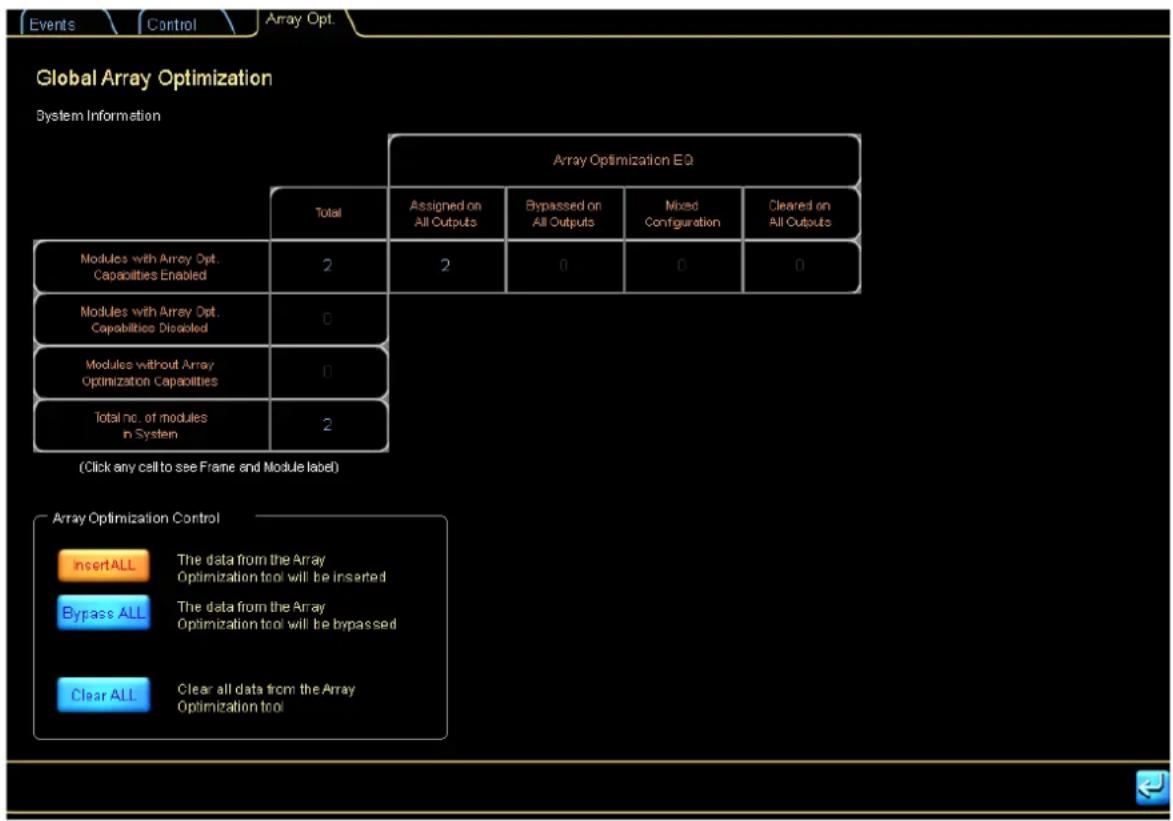
Figure 23-4: Global Array Optimization, System information and Control
23.4 Log Files
For every Lake Controller session, one or two sets of log files are created (statistical log files require a Lake-enabled amplifier on work area). These XML files can be viewed as text or imported into Microsoft Excel. The files are located in the installation folder \logs, also available via a Windows Start menu shortcut.

To import log files into Microsoft Excel, right click on the file and choose OPEN WITH->EXCEL. For Excel 2003 and later, select OPEN AS AN XML LIST.

Earlier versions of Excel (pre-2003) do not provide full XML support and should not be used for log file import.
23.4.1 Statistical log files
Assuming at least one Lake-enabled amplifier is present in the current system configuration, the Lake Controller software will continuously log statistical information to a file. The logged data includes amplifier operation statistics in addition to faults and warnings.
23.4.2 Event Log
When Lake Controller is started, the EVENT LOG currently viewable in the EVENT LOG tab is written to a file and continues to do so in 2 min intervals until the Lake Controller is closed. The name of the file is the date and time from when the Lake Controller is started. The interval can be changed in the iC.ini file.
24. Keyboard Shortcuts
This section describes various keyboard shortcuts that are available when using a computer with a keyboard attached.
24.1 Enabling/Disabling Keyboard Shortcuts
Keyboard shortcuts are enabled by default. To disable keyboard shortcuts, perform the following steps:
- From HOME, tap USER PREFERENCES.
- Tap KEYBOARD SHORTCUTS [F5].
All keyboard shortcuts will be disabled and the function key labels will be removed from the buttons on the button bar. Tap KEYBOARD SHORTCUTS again to enable this feature.
24.2 General Keyboard Shortcuts
▶ ESCAPE - Equivalent to tapping NO or CANCEL for warning messages, dialog boxes and when using the on screen keyboard. Equivalent to tapping EXIT on button bar menus ▶ ENTER - Equivalent to tapping YES or OK for warning messages, dialog boxes and when using the on screen keyboard. ▶ MOUSE WHEEL - Equivalent to dragging the selected filter point up or down on XOVER or EQ screens.
24.3 Button Bar Shortcuts
24.3.1 Context Switching
To change a context view using the keyboard, perform the following steps:
- Hold down the C key.
- Tap the number on the keyboard that corresponds to the required context.
- Release the C key.
24.3.2 Main Navigation/Function Buttons
The [F1] through [F10] function keys are mapped sequentially from left to right to the main navigation and function buttons on the button bar. Pressing a function key will have the same effect as tapping the associated button with a touch-screen pen or pointer. This applies to all button bar buttons throughout the system.
24.3.3 Undo/Redo
To undo/redo the last LEVELS or EQ change, perform the following steps:
- Hold down the CTRL key.
- Tap the Z key.
This function toggles between undo and redo, providing the same effect as tapping the Undo/Redo button.
24.3.4 Shortcut Combination Keys
Throughout the following sections, specific actions are described. These are based on the generic rules for certain keys as shown below:
TAB: Moves forward, to the right, through pages in the MAIN work area, screens, or EQ overlays. SHIFT: Used in conjunction with TAB, reverses the order or page/screen/overlay navigation. Used with arrow keys, switches between FINE and NORMAL adjustment mode (LEVELS/EQ/XOVER/AUX). CAPS LOCK: Permanently selects FINE or NORMAL adjustment mode (LEVELS/EQ/XOVER/AUX). Does not work in conjunction with TAB. CTRL: Allows a key to perform another related function.
24.4 EQ, LEVELS, XOVER, and AUX Screen Shortcuts
For the purposes of keyboard shortcut navigation, the TAB function cycles through all LEVELS screens, if a LEVELS screen is selected, or through all XOVER/AUX/EQ screens if a XOVER/AUX/EQ screen is selected.
CTRL + TAB: Cycles forward through the visible screens for either Levels or XOVER/Aux/EQ, depending on what is currently selected. TAB: Moves forward (to the right) through visible screens/overlays. When the last screen/overlay is reached, it will cycle back to the first screen/overlay. SHIFT + TAB: Moves backward (to the left) through visible screens/overlays. On the screen overlay, it will cycle to the last screen/overlay.
24.4.1 GEQ Overlay Shortcuts
LEFT ARROW: Moves the GEQ selector one filter to the left. RIGHT ARROW: Moves the GEQ selector one filter to the right. UP ARROW: Increases the gain of the selected GEQ filter (Fine). UP ARROW + SHIFT/CAPS LOCK: Increases the gain of the selected GEQ filter (Coarse). DOWN ARROW: Decreases the gain of the selected GEQ filter (Fine). DOWN ARROW + SHIFT/CAPS LOCK: Decreases the gain of the selected GEQ filter (Coarse).
24.4.2 PEQ Overlay Shortcuts
▶[1]: Adds a low-shelf filter at 125 Hz. ▶[2]: Adds a Parametric filter at 500 Hz. ▶[3]: Adds a Mesa filter with low frequency at 830 Hz and high frequency at 1.2 kHz. ▶[4]: Adds a high-shelf filter at 8 kHz.
[E]: Enables FILTER EDIT mode for the manual entry of gain/freq/bandwidth via a keyboard. ▶[G]: The gain value for the selected filter is displayed in the on-screen keyboard. [F]: The frequency value of the selected filter is displayed in the on-screen keyboard. ▶[CTRL] + [F]: The high-frequency value of a selected Mesa filter is displayed in the on-screen keyboard. [B]: The bandwidth value of the selected filter is displayed in the on-screen keyboard. ▶[CTRL] + [B]: The high-bandwidth of the selected Mesa filter is displayed in the on-screen keyboard. ▶[<]: Moves the center frequency of the selected filter to the left (Fine). [SHIFT] or [CAPS LOCK] + [<]: Moves the center frequency of the selected filter to the left (Coarse). ▶[>]: Moves the center frequency of the selected filter to the right (Fine). [SHIFT] or [CAPS LOCK] + [>]: Moves the center frequency of the selected filter to the right (Coarse). LEFT ARROW: Selects the filter to the left of the currently selected filter. ▶RIGHT ARROW: Selects the filter to the right of the currently selected filter. ▶UP ARROW: Increases the gain of the selected PEQ filter (Fine). [SHIFT] or [CAPS LOCK] + UP ARROW: Decreases the gain of the selected PEQ filter (Coarse). ▶DOWN ARROW: Decreases the gain of the selected PEQ filter (Fine Adjustment).
[SHIFT] or [CAPS LOCK] + DOWN ARROW: Decreases the gain of the selected PEQ filter (Coarse). ▶[Q]: Increases bandwidth of selected filter, or the lowest frequency segment of a Mesa filter (Fine). [SHIFT] or [CAPS LOCK] + [Q]: Increases bandwidth of selected filter, or the lowest frequency segment of a Mesa filter (Coarse). [W]: Decreases bandwidth of selected filter, or the lowest frequency segment of a Mesa filter (Fine). [SHIFT] or [CAPS LOCK] + [W]: Decreases bandwidth of selected filter, or the lowest frequency segment of a Mesa filter (Coarse).
▶[A]: Increases the high bandwidth of a selected Mesa filter (Fine).
[SHIFT] or [CAPS LOCK] + [A]: Increases the high bandwidth of a selected Mesa filter (Coarse). ▶[S]: Decreases the high bandwidth of a selected Mesa filter (Fine). [SHIFT] or [CAPS LOCK] + [S]: Decreases the high bandwidth of a selected Mesa filter (Coarse). ▶[CTRL] + [Q]: Moves the low-frequency segment of a Mesa filter to the left. ▶[CTRL] + [W]: Moves the low-frequency segment of a Mesa filter to the right. ▶[CTRL] + [A]: Moves the high-frequency segment of a Mesa filter to the left. ▶[CTRL] + [S]: Moves the high-frequency segment of a Mesa filter to the right.
24.4.3 BLEQ Overlay Shortcuts
[E]: Enables FILTER EDIT mode for the manual entry of gain/freq/bandwidth via a keyboard. [G]: The gain value for the selected filter is displayed in the on-screen keyboard. [F]: The frequency value of the selected filter is displayed in the on-screen keyboard. [CTRL] + [F]: The high-frequency value of a selected Mesa filter is displayed in the on-screen keyboard. [B]: The bandwidth value of the selected filter is displayed in the on-screen keyboard. [CTRL] + [B]: The high-bandwidth of the selected Mesa filter is displayed in the on-screen keyboard. [<]: Moves the center frequency of the selected filter to the left (Fine). [SHIFT] or [CAPS LOCK] + [<]: Moves the center frequency of the selected filter to the left (Coarse). [>]: Moves the center frequency of the selected filter to the right (Fine). [SHIFT] or [CAPS LOCK] + [>]: Moves the center frequency of the selected filter to the right (Coarse). LEFT ARROW: Selects the filter to the left of the currently selected filter. RIGHT ARROW: Selects the filter to the right of the currently selected filter. UP ARROW: Increases the gain of the selected filter (Fine).
[SHIFT] or [CAPS LOCK] + UP ARROW: Decreases the gain of the selected filter (Coarse). DOWN ARROW: Decreases the gain of the selected filter (Fine Adjustment). [SHIFT] or [CAPS LOCK] + DOWN ARROW: Decreases the gain of the selected PEQ filter (Coarse). [Q]: Increases bandwidth of selected filter, or the lowest frequency segment of a Mesa filter (Fine). [SHIFT] or [CAPS LOCK] + [Q]: Increases bandwidth of selected filter, or the lowest frequency segment of a Mesa filter (Coarse). [W]: Decreases bandwidth of selected filter, or the lowest frequency segment of a Mesa filter (Fine). [SHIFT] or [CAPS LOCK] + [W]: Decreases bandwidth of selected filter, or the lowest frequency segment of a Mesa filter (Coarse). [A]: Increases the high bandwidth of a selected Mesa filter (Fine). [SHIFT] or [CAPS LOCK] + [A]: Increases the high bandwidth of a selected Mesa filter (Coarse). [S]: Decreases the high bandwidth of a selected Mesa filter (Fine). [SHIFT] or [CAPS LOCK] + [S]: Decreases the high bandwidth of a selected Mesa filter (Coarse). [CTRL] + [Q]: Moves the low-frequency segment of a Mesa filter to the left. [CTRL] + [W]: Moves the low-frequency segment of a Mesa filter to the right. [CTRL] + [A]: Moves the high-frequency segment of a Mesa filter to the left. [CTRL] + [S]: Moves the high-frequency segment of a Mesa filter to the right.
24.4.4 XOVER/AUX Screen Shortcuts
[1]: Adds a low-shelf filter to the selected output at 125 Hz. [2]: Adds a parametric filter to the selected output at 500 Hz. [3]: Adds an all-pass filter to the selected output at 1 kHz. Available in Designer Mode only. [4]: Adds a high-shelf filter to the selected output at 8 kHz. [G]: The gain value for the selected filter is displayed in the on-screen keyboard for instant editing. [F]: The frequency value of the selected filter is displayed in the on-screen keyboard for instant editing. [B]: The bandwidth value of the selected filter is displayed in the on-screen keyboard for instant editing. [O]: The order of a selected all-pass filter is displayed in the on-screen keyboard for instant editing. Not applicable to any other filter type and available only in Designer Mode. [<]: Moves the center frequency of the selected filter to the left (Fine). [SHIFT] or [CAPS LOCK] + [<]: Moves the center frequency of the selected filter to the left (Coarse).
[>]: Moves the center frequency of the selected filter to the right (Coarse). [SHIFT] or [CAPS LOCK] + [>]: Moves the center frequency of the selected filter to the right (Fine). LEFT ARROW: Selects the filter to the left of the currently selected filter. RIGHT ARROW: Selects the filter to the right of the currently selected filter. UP ARROW: Increases the gain of the selected EQ filter (Fine).
[SHIFT] or [CAPS LOCK] + UP ARROW: Increases the gain of the selected EQ filter (Coarse).
DOWN ARROW: Decreases the gain of the selected EQ filter (Fine).
[SHIFT] or [CAPS LOCK] + DOWN ARROW: Decreases the gain of the selected EQ filter (Coarse).
[Q] Increases the bandwidth of the selected EQ filter (Fine).
[SHIFT] or [CAPS LOCK] + [Q]: Increases the bandwidth of the selected EQ filter (Coarse).
[W]: Decreases the bandwidth of the selected EQ filter (Fine).
[SHIFT] or [CAPS LOCK] + [W]: Decreases the bandwidth of the selected EQ filter (Coarse).
24.4.5 LEVELS Screen Shortcuts
[0] + [ENTER]: Displays on-screen keyboard for instant input-level editing of selected level type. [1] + [ENTER]: Displays on-screen keyboard for OUT 1-level editing for selected level type. [2] + [ENTER]: Displays on-screen keyboard for OUT 2-level editing for selected level type. [3] + [ENTER]: Displays on-screen keyboard for OUT 3-level editing for selected level type. [4] + [ENTER]: Displays on-screen keyboard for OUT 4-level editing for selected level type. [5] + [ENTER]: Displays on-screen keyboard for OUT 5-level editing for selected level type. [6] + [ENTER]: Displays on-screen keyboard for OUT 6-level editing for selected level type. [0] + UP or DOWN ARROW: Increases or decreases INPUT level for selected level type (Fine). [1] + UP or DOWN ARROW: Increases or decreases OUT 1 level for selected level type (Fine). [2] + UP or DOWN ARROW: Increases or decreases OUT 2 level for selected level type (Fine). [3] + UP or DOWN ARROW: Increases or decreases OUT 3 level for selected level type (Fine). [4] + UP or DOWN ARROW: Increases or decreases OUT 4 level for selected level type (Fine). [5] + UP or DOWN ARROW: Increases or decreases OUT 5 level for selected level type (Fine). [6] + UP or DOWN ARROW: Increases or decreases OUT 6 level for selected level type (Fine). [0] to [6] + UP or DOWN ARROW + [SHIFT] or [CAPS LOCK]: Coarse adjustment mode for the levels of the number/arrow combinations listed above.
25. External Control Interfaces
This chapter describes the options for interfacing with Lake devices from external controllers and interfaces. Functionality is often product specific; please refer to the relevant product operation manual for additional information.
25.1 GPIO (LM Series Only)
LM Series devices provide General Purpose Input Output functionality (GPIO) allowing interface with external systems. Unlike the other forms of external control described in this chapter, GPIO provides full configuration options via the Lake Controller or via the front panel of LM Series device.
For information on configuring GPIO via the Lake Controller, please refer to section 8.2.3 on page 132 of this manual. For information on configuring GPIO via the Front Panel of the LM Series device, please refer to the Front Panel Interface chapter of the LM Series Operation Manual. For information on GPIO hardware, including a pinout reference, please refer to the Back Panel Interface chapter of the LM Series Operation Manual.
25.2 AMX® and Crestron® Control
25.2.1 DLM Protocol
The Direct Lake Messaging third party protocol (DLM) is provided for all devices except MY8-LAKE, allowing integration with external control and monitoring applications such as AMX and Crestron. Please email support@lakeprocessing.com to obtain DLM Control Protocol technical information.
The extensive function control list includes:
▶ Frame & Module labelling - Adjustment of Module input gain, delay, mute, phase and label
Adjustment of module output gain, delay, MaxRMS & MaxPeak limiters, mute, phase and label
Input configuration, Iso-Float & AES Termination controls
Standby power control, factory reset options
Preset Recall (all devices)
Preset Store (not applicable for MY8-LAKE)
Adjustment of amplifier gain and Voltage Peak Limiter (Lake-enabled Amplifiers only). Activation of LoadPilot on individual power output channels (PLM+ and D Series only). Activation of data transmission for amplifier output voltage and current via Dante (Lake-enabled Amplifiers only).
Additionally, the following parameters may be retrieved from all devices (except MY8-LAKE) using the DLM Protocol:
Preset Name, Firmware Version, Unique ID and Mac Address. IP Address and Subnet Mask. Dante Break-In and Enable Status. Input Activity and Configuration. Metering and Fault Information - Current DSP > Amp Routing (Lake-enabled Amplifiers only).
Output channel Impedance Measurement in Ohms (PLM+ and D Series only).
These external control systems must form valid Ethernet packets that follow the requirements of the network packet specification. Please email support@lakeprocessing.com to obtain the information required for integration.
25.3 Q-SYS Plugin
For PLM+ and D Series, there is a native Q-SYS Plugin that can be downloaded from labgruppen.com which integrates natively in the Q-SYS environment.
26. Command Line Options
26.1 Overview
The Lake Controller provides a number of command-line options to enable or disable certain functionality. These options may be entered when launching the Controller from a command prompt, or may be set using a shortcut's target option.
As an example, the following steps describe how to configure a shortcut on the desktop to launch the Lake Controller in daylight mode:
- Right-click on the Microsoft Windows desktop and select NEW > SHORTCUT.
- When asked for the location of the item, type the following, ensuring you use quotation marks as shown below, and exchange LAKE CONTROLLER vX.X for the Lake Controller installation directory.
"C:\Program Files\Lake\Lake Controller vX.X\Lake Controller.exe" daylight
- Tap NEXT.
- When asked for a shortcut name, enter OUTDOOR.
- Tap FINISH.

Multiple shortcut command line options may be used by separating them with a space.
26.2 Reference
Table 26-1 on page 306 describes the options for command line functionality.
| Command Description | |
| daylight | Forces daylight mode when opening the Lake Controller. |
| digswitch | Enables the feature Global Input Router Priority. Also enables a button labelled "Prio" at the top right of the Lake Controller next to the minimize button.Tapping this button provides additional options to allow the entire system to be switched instantly between Input priority 1,2,3 or 4, or reverted to independent automatic selection, or to check the current status of all frames.[Prio 1] forces all online devices in the current system configuration to use forced priority 1 input for all input routers. Prio 2, 3 and 4 work on the same way for the associated input priorities.[Auto] reverts all inputs of all frames to automatic priority selection.[Check] displays a report of input router status for frames in the current system configuration. |
| emulation | Disables hardware Graphics-card based acceleration and enables software emulation for Graphics acceleration. This may be useful for devices with low-end Graphics cards, where virtual control of the Lake Controller is required, or where video hardware problems are encountered. When this command is enables, the systemmem command has no effect as all data is stored in memory. This option may decrease performance. |
| netfix | Enables the automatic disabling of unused multiple network adapters in the case of communication errors. Only use if you have multiple network cards and are experiencing communication problems. |
| nodblclick | Disables the use of double-clicking on the menu bar to rename Groups or select files. |
| nonfullscreen | This mode stops the automatic change of any video card settings during the Controller session; therefore correct manual settings must be made. The whole screen is still used. This is not a windowed mode option. |
| offline | Forces the Controller into offline mode during start-up so no network adapter is selected. |
| systemmem | Forces the use of system memory (RAM) instead of dedicated or shared video memory on the Graphics-card (GPU) for certain Graphics resources. This may be useful if available video memory is exceeded, or if other video-memory related issues are encountered. If this option does not resolve the encountered problem, try using the emulation option described above. This option may decrease performance. |
| reportversions | Will display the minimum required Lake Controller version to recall the Module or System file. |
| startcontrolplugins | Will automatically start all control plugins located in the plugins folder directly on LC startup. |
| forcenetwork | Forces Lake Controller to use a specific NIC (Network Interface Card), and hence doesn't show the NIC selection menu normally displayed when multiple NICs are available on the computer. For an NIC with IP address 169.254.10.10, the complete string should be forcenetwork=169.254.10.10 |
| forcesystemfile | Will do a RECALL AS NEW SYSTEM directly on Lake Controller startup to the specified system file in the System files folder. No “Load Last” dialog is displayed. The complete string should be forcesystemfile=XYZ.csc |
| comparesystemfile | Will do a RECALL COMPARE directly on Lake Controller startup to the specified system file in the System files folder. No “Load Last” dialog is displayed. The complete string should be comparesystemfile=XYZ.csc |
Table 26-1: Command Line Options
27. Firmware Update
27.1 Backup System Configuration and Presets
While every effort is made to retain all settings in the device during the firmware upgrade procedure, it is highly recommended that the following steps are followed:
- Open the previously used version of the Lake Controller software.
- Tap YES when asked "Do you want to recall the last configuration?"
- Store the current system configuration using the old version of the Lake Controller.
- Open the previous version of the associated Preset Manager and store all Presets that are contained within all Lake devices on the network.
- Proceed to section 27.2 and update the device firmware.
27.2 Updating Firmware
The Lake Firmware Update Utility provides a fast firmware upgrade procedure for small or large networks of Lake devices. The firmware bundle includes all internal components of firmware needed for the device, including Dante firmware; no additional update is required.
Follow the steps below to upgrade your device:
- Install the latest version of the Lake Controller software.
- Power on all devices, and connect using a wired network.
- Select the Lake Firmware Update Utility via Windows START > PROGRAMS > LAKE CONTROLLER By default, this utility is located in a folder labeled: Lake Controller vX.X > Firmware Update Utilities
- Select the platform to update from the dialog that is displayed as shown in Figure 27-1.

Figure 27-1: Device Platform Selection Dialog
If more than one network adapter is enabled, a screen similar to that shown in Figure 27-2 will be displayed. Always ensure you select a wired network for updating firmware as a loss in connectivity could corrupt the firmware.

Figure 27-2: Network Adapter Selection
- Select the wired adapter to which the Lake devices are connected.
The Lake devices will appear in a list with their current firmware versions displayed, similar to that shown in Figure 27-3. The firmware version to be loaded is shown at the top of the screen (target firmware); this will default to the latest version available.

Figure 27-3: Lake Update Utility Main Screen
For PLM+ and D Series, the firmware update utility must be able to read the Dante component before the firmware update can start; ensure the network adapter selected for firmware update is on the same subnet as Dante (169.254.x.x) and ensure the Lake Update Utility has full access through the firewall.

An hourglass will display with the text "Dante version..."; if this does not complete within 30 seconds, press the Refresh Dante button. If the issue continues, open the Dante Controller and press "Reload Device Information", or restart the computer.
- Tap SELECT OLD and then UPDATE. A warning message appears.

Figure 27-4: Firmware Update Warning Message
- Tap OK in response to the warning message. All selected devices are updated in parallel with the latest firmware. A green tick indicates the firmware is already at the latest version, a percentage indicates the update status for the devices currently being updated, and a red cross indicates the firmware is old and is awaiting update or the device requires a power-cycle to complete the upgrade.
| Frame ID | Name | Version |
| 6c000011:d6fd5401 | 14000 | 34% |
| cc000010:fcd4f501 | 10000Q | 34% |
| 1c000011:d71dde01 | 14000 | 34% |
| 4a000010:fce19b01 | 10000Q | 37% |
Figure 27-5: Firmware Update Status
- Wait for all devices to be updated. For PLM+ and D Series (with firmware >2.58), the firmware update process will include a automatic power cycle.
For PLM, LM and MY8-LAKE, when the firmware is updated, a warning advises that the mains power must be cycled (using the standby button on the Front Panel is not sufficient). For the MY8-LAKE, please power-cycle the host device.

PLM+ and D Series devices with a firmware version later than v2.59 will automatically power cycle; this is clearly indicated in the update tool.

Devices that require a manual power cycle are clearly highlighted in the update tool.
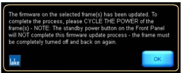
Figure 27-6: Firmware Update Confirmation
- Cycle the power of each Lake device as indicated in the update tool.

Mains power must be cycled to complete the firmware update. Pressing the front panel standby button will not complete the upgrade.
- Tap OK, then tap EXIT to quit the firmware update utility.
For Lake-enabled amplifiers, if the firmware includes a change for amplifier, front panel or Dante components, additional upgrade activity and progress will be indicated on the front panel. After an upgrade of the amplifier firmware, the unit will reboot automatically.

Firmware upgrades for PLM+ and D Series devices will take longer to update when the release includes new Dante firmware. Do not interrupt a firmware upgrade procedure.
27.3 Incompatible Firmware Notification in Lake Controller
If a device with incompatible firmware (older or newer than this version of the Lake Controller can support) is placed in the Lake Controller work area, an indication similar to that shown in Figure 27-7 will be displayed on the associated Module icons.
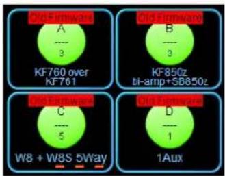
Figure 27-7: Old Firmware Notification in the Lake Controller
The firmware cannot be updated from within the Lake Controller; to update firmware, quit the Lake Controller and access Lake Firmware Update Utility as described in section 27.2.
27.4 Remote Power Cycle
For PLM+ and D Series devices (with firmware later than 2.58), it is possible from within the Lake Update Utility to perform a remote power cycle. This is done via the "Power Cycle Selected" button.
Select the frames in the list and tap "Power Cycle Selected" and these frames will perform a power cycle.
This is helpful when settings that require a power cycle have been changed from the Lake Controller, for example Dante Slave Only or IP Config settings. After these changes, start Lake Update and perform the required power cycle remotely.
28. Preset Manager
The Lake Preset Manager Utilities are provided as separate applications for each Lake device. These utilities operate on any PC with Microsoft Windows XP or above, and a standard Ethernet network interface.
For further details about presets, please refer to section 7.10 of this manual.
Using the Preset Manager utilities, a sound engineer can easily manage the presets that reside on the device. Presets can be created, named, copied, locked, and transferred across multiple devices of the same type and may also be set to exclude the recall of Frame labels and Dante device names when a preset is recalled.
Presets may be stored into PC files (called bank files) for backup or transfer purposes; these files have different file extensions depending on the device type.
There are two Preset Manager utilities, one for each range of Lake devices:
▶ Preset Manager (PLM, PLM+ and D Series)
▶ LM Series Preset Manager (LM Series)

PLM+ and D Series presets are cross-compatible between devices in these product ranges. Other product presets are specific to each product.
At least one Lake device must be connected to proceed with this tutorial. This tutorial assumes the use of a factory-reset device; if necessary, please refer to your associated product operation manual for information on how to restore the factory configuration.
28.1 Starting the Lake Preset Manager
To start the Lake Preset Manager, select the Windows Start menu, then select Programs > Lake Controller vX.X > Preset Manager Utilities.
Select the preset manager applicable to your product.

Figure 28-1: Preset Manager Default State
28.2 Screen Layout
28.2.1 Main Area
The main area is divided into four columns labeled ABCD in Figure 22 1. By default, columns A&B display the contents for the presets folder located on the computer and Columns C&D show the online Frames.

The current directory path is displayed above column A / C when COMPUTER is selected. The Preset Manager stores this location upon exiting the program, and restores it when restarted.
28.2.2 Button Bar Interface
The button bar, labeled E in Figure 28-1 follows the same logic as the Lake Controller, three colors indicate the button status.
▶ ORANGE - currently selected function
BLUE - available function based on current selection - GRAY - unavailable function based on current selection
28.3 Working with Frames
28.3.1 Selecting a Frame
To select a single Frame, tap the associated row in column C. The selected Frame is highlighted orange. Buttons are enabled and disabled depending on the current selection. With one or more Frames selected, the presets are displayed in the column to the right.

Figure 28-2: Online Frames
28.3.1.1 Rename Frame [F5]
Allows the name of the selected Frame to be changed. Only alphanumerical characters are accepted.
28. 3.1. 2 Select Multiple [F6]
Allows the selection of multiple Frames/presets by tapping multiple times on column C or D. Equivalent to holding down [CTRL] on a keyboard.
28.3.1.3 Set Frame Password/Change Password [F7]
Sets or changes the current Frame password.
28.3.2 Storing a Preset
To store the current configuration as a preset on an online Frame:
- Select an empty slot in column D, and tap STORE PRESET [F2].
- Enter a name in the popup window, and tap OK.
The current configuration is now stored as a preset on the selected Frames.

Figure 28-3: List of Presets for Selected Frame
When an existing preset is selected, functions available are:
28.3.2.1 Recall Preset [F1]
Loads the selected preset as the current configuration for selected Frames.
28.3.2.2 Store Preset [F2]
Stores the current configuration as a preset on the selected Frames.
28.3.2.3 Clear Preset [F4]
Clears the selected presets on the selected Frames.
28.3.2.4 Rename Preset [F5]
Renames the selected preset on the selected Frames.
![Lab Gruppen PLM 5K44 - Rename Preset [F5] - 1](/content/2026/07/1419186/images/4d1ac21a201a5c5080936a094d150a24b8e61599f85db43880957157d1f3727b.jpg)
If one or more of the selected Frames contains a different configuration in a particular preset location, *MISMATCH* displays as the name for that system preset location.
The RECALL PRESET and RENAME PRESET buttons are disabled when a location is selected for multiple Frames that contain a preset mismatch.
28.3.2.5 Select Multiple [F6]
Allows the selection of multiple items. Equivalent to holding down [CTRL] on a keyboard.
28.3.2.6 Set Frame Password/Change Password [F7]
Sets or changes the current Frame password.
28.3.2.7 Lock Preset/Unlock Preset [F8]
Presets can be locked to prevent changes or deletion. Locking the first preset on a Frame requires a Frame password to be set. When a preset is locked, a lock icon is displayed next to it and next to its Frame. Any further operation on that preset requires the user to enter the Frame password.

Figure 28-4: Online Frame with Locked and Unlocked Presets
In this example, Presets 1+4 are locked, and Presets 2+3 are unlocked. When a Preset is locked, the Exclude/Include Labels function may be changed without the need to enter a password. Please refer to Exclude/Include Labels section below for further information on this feature.
Unlocking a preset removes its lock but not the associated Frame password.
![Lab Gruppen PLM 5K44 - Lock Preset/Unlock Preset [F8] - 2](/content/2026/07/1419186/images/be52bd9c7b7afebab5e1133634d656d5ae8e9892a408ddb4b729c3d2d3cf536d.jpg)
To remove an existing Frame password, select the Frame, tap CHANGE PASSWORD, enter the current password, then tap OK twice.


Figure 28-5: Online Frame with Locked Presets and Password Removed
![Lab Gruppen PLM 5K44 - Lock Preset/Unlock Preset [F8] - 5](/content/2026/07/1419186/images/9dc346d4bb52b8fcba86ca9afdd92714d0fc09391f02eacdea5853a698a74450.jpg)
The open green lock displayed in Figure 28-5 identifies the preset is locked but no password is set. Setting a FRAME PASSWORD will lock the preset again.
28.3.2.8 Exclude/Include Labels [F9]
Presets may be set to exclude the Frame label and Dante device name by using the EXCLUDE LABELS function. When the Exclude Labels function has been activated for a Preset (indicated by a crossed tag icon as shown on Presets 2+4 in Figure 28-5), the Frame label and Dante device name will not be changed from the existing setting when the Preset is recalled.
The Exclude/Include Labels function works on individual and multiple presets in bank files and online frames based on the currently selected preset or presets.
This function is available only via the Preset Manager utility, but the Exclude Labels status for each Preset is visible via the Lake Controller as shown in Figure 7-3 on page 119.
![Lab Gruppen PLM 5K44 - Exclude/Include Labels [F9] - 1](/content/2026/07/1419186/images/4905c7a9afeceb764369a73923433c5075a0d303bca53444b38329b522114e11.jpg)
By default Presets are set to Exclude Labels when being transferred between a bank file and an online frame. If the Frame label and Dante device name is specifically required, use the Include Labels function to manually change this setting per Preset.
28.4 Working with Bank Files
A bank file is a software file, stored on a computer or external storage device, that contains the details for all presets on a device. It can be used as a backup file, as well as to transfer presets between devices. For LM and PLM Series devices, a bank file is specific to each device type; for PLM+ and D Series devices the bank files are compatible across all device and model variations.

It is recommended to Exclude Labels on all Presets when transferring the same Presets or Bank Files to multiple devices. If Exclude Labels is not set, the device's Frame Label and Dante device name will change during Preset Recall to the value present when the Preset was created.
28.4.1 Creating a New Bank File
A new empty bank file is created by tapping NEW BANK [F3]. This button is available only when the COMPUTER column is selected, column A by default.
After entering a bank file name, either double-tap the bank file in column A, or select the bank file and tap OPEN [F1]. The empty bank file is shown in column B.
A bank file can also be created by dragging an online Frame (column C) into column A (or vice versa). This bank file contains all presets from the dragged Frame, and thus may not be empty. An automatic name is set for that bank file.
Figure 28-6 shows a bank file containing four presets with varying Lock and Exclude Label statuses.
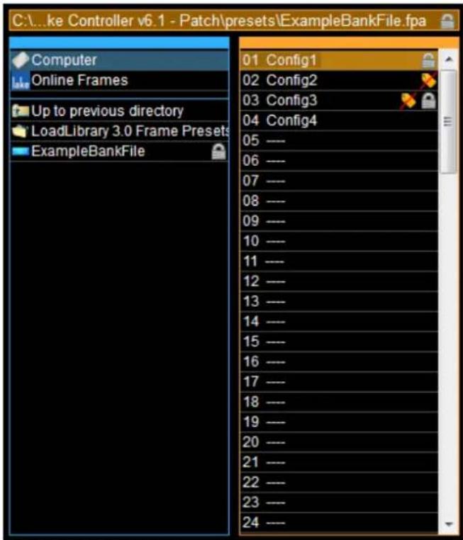
Figure 28-6: Open Bank File in Default Presets Folder
28.4.2 Bank File / Folder Functions
When a bank file or a folder is selected, the following options are available.
28.4.2.1 Open [F1]
The action of OPEN [F1] depends on what is currently selected. If a bank file is selected, it displays the presets of the selected bank file in column C or D. If a folder is selected, it displays the contents of the folder in column A or B.
28.4.2.2 New Folder [F2]
Creates a new folder in the working directory.
28.4.2.3 Delete [F4]
Deletes the selected items.
28.4.2.4 Rename [F5]
Renames the selected item.
28.4.2.5 Select Multiple [F6]
Allows the selection of multiple items. Equivalent to holding down [CTRL] on a keyboard.
28.4.2.6 Set Bank Password/Change Password [F7]
Sets or changes the password for the selected bank file. When a password is set, a lock icon is displayed next to the bank file and on any locked Presets. Bank File and Frame passwords follow the same logic.
![Lab Gruppen PLM 5K44 - Set Bank Password/Change Password [F7] - 1](/content/2026/07/1419186/images/72137dc04b31fa61d865098ce6c3be0b5686580c461ba9908556c10de2490355.jpg)
To remove an existing password, tap CHANGE PASSWORD, enter the current password, then tap OK twice.
28.4.3 Preset Functions
When a preset in a bank file is selected, the following actions are available.
28.4.3.1 Clear Preset [F4]
Deletes the selected presets from the bank file.
28.4.3.2 Rename Preset [F5]
Renames the selected preset in the bank file.
28.4.3.3 Select Multiple [F6]
Allows the selection of multiple items using multiple single tap actions; equivalent to holding down [CTRL] on a keyboard.
28.4.3.4 Set Bank Password/Change Password [F7]
Sets or changes the password for the selected bank file. When a password is set, a lock icon is displayed next to the bank file and on any locked Presets. Bank file and Frame passwords follow the same logic.
![Lab Gruppen PLM 5K44 - Set Bank Password/Change Password [F7] - 1](/content/2026/07/1419186/images/dd8445ca299df635fce0ff3e356a9b74f752e22dd5b7e221fe6ad221387fffd7.jpg)
To remove an existing password, tap CHANGE PASSWORD, enter the current password, then tap OK twice.
28.4.3.5 Lock / Unlock Preset [F8]
Locks or unlocks the selected preset/s in a bank file as described in section 28.3.2.7.
28.4.3.6 Exclude / Include Labels [F8]
Sets the Exclude / Include Labels function for the selected Preset/s as described in section 28.3.2.8.
28.4.4 Transferring Presets between Bank Files and Devices
To transfer Presets between Devices and Bank Files, select the Preset(s) and drag between column B and column D as shown in Figure 27-7.
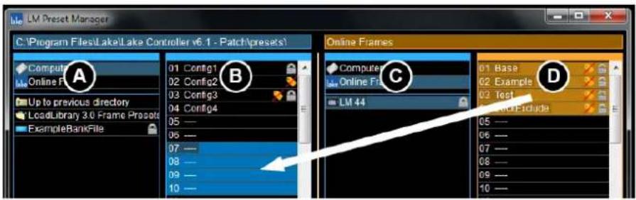
Figure 27-7: Transferring Presets from a Device to a Bank File
In this example, files are copied from the device to the computer (bank file) and will appear in the destination column as shown in column B in Figure 27-8 once the transfer is complete. Bank file presets can be transferred in the same way as indicated below.

Figure 27-8: Transferring Presets from a Bank File to a Device

The Exclude Labels setting is set automatically when transferring presets between a bank file and an online frame.
28.4.5 Bank Filename Extensions
Each Lake device has a unique file extension for Bank files as shown in Table 27-1.
| Lake Device Bank Filename Extension | |
| PLM+ and D Series (all models) .lpf | |
| PLM 20000Q .tpa / .tsb ^ | |
| PLM 14000 .ppa | |
| PLM 10000Q .gpa | |
| LM 44 .fpa | |
| LM 26 .lpa * | |
| 20000 DP .tsb / .tpa ^ |
Table 27-1: Bank File Extensions

^ PLM 20000Q and 20000 DP Frame Preset files are cross-compatible.

.* LM 26 and legacy Dolby Lake Processor file extensions are identical, although the Presets contained within these files are not compatible across these device types.
28.5 Common Functionality
28.5.1 Exit [F10]
Closes the Preset Manager application.
29. IP Address Reference
In most applications, the IP addresses and other configuration parameters of the underlying Ethernet system will not need to be adjusted by the end user. If a system requires advanced networking requirements, however, such as the partitioning of a high-bandwidth Ethernet backbone into virtual local area networks (VLANs), then a qualified network engineer may need to make adjustments to the default Ethernet configuration of the Lake device and the computer running the Lake Controller software. This chapter provides reference information pertaining to Ethernet configuration.
29.1 Network Essentials
Ethernet is a cost-effective and easy-to-configure system for networking personal computers, servers, local area networks (LANs), industrial and professional equipment, and even provides the fundamental transport backbone of the Internet. Since Ethernet is widely used for many applications, there are a number of rules governing network configuration to ensure there are no conflicts between multiple devices.
IP addresses provide the unique identifier of each node (unit of network hardware) on an Ethernet network. The address uniquely identifies the network that the node is on, as well as uniquely identifying the node on that network. For example, this unique identifier ensures that personal computers all around the world do not clog the Internet with messages intended for local data transfers.
Since Ethernet is used locally and globally, Ethernet standards reserve ranges of IP addresses for various applications. Public IP addresses are used on the Internet, and should not be used in LANs. A range of private IP addresses have also been defined and set aside for use on internal networks. These private IP addresses can be used on internal networks by anyone, as the Internet's backbone routers will not route packets with these addresses.
Lake devices and the Lake Controller software have been developed and tested for use on internal networks that are not intended to be connected to the Internet. Therefore, we recommend that you use private IP addresses when configuring the network.
29.2 Factory Reset Configuration
A factory reset Lake device will have an IP address set in the Automatic Private IP Address range 169.254.x.x with a subnet mask of 255.255.0.0.
Dante digital audio networking utilizes the Dante Discovery service to automatically identify all Dante devices on the network. It is imperative that the Dante Controller, which includes installation of the Dante Discovery service, is installed on the Lake Controller PC for Dante to function.
The default starting point is for all device to be left with this factory reset automatic IP address range, with the Controller PC configured to obtain an IP address automatically. If problems are encountered, or you require a more complex configuration, please refer to a network specialist, and in the case of a Dante audio network, refer also to:
Dante specific documentation included in the Lake Controller software installation ▶Lake Processing forum @ http://support.labgruppen.com/home
If desired, you can also use Class A (except for PLM+), Class B (recommended) or Class C private IP address ranges. These addresses require additional configuration, and thus more knowledge of IP addresses and networking. Table 29-1 shows a selection of private IP address ranges recommended for use with the Lake device and Lake Controller network. It is recommended that all hardware is configured with a private IP address within these ranges.
Class Range
A 10.x.x.x
B 169.254.x.x (Default - Automatic Private IP Address) - RECOMMENDED
C 172.16.x.x through 172.31.x.x*
D 192.168.0.x through 192.168.255.x
Table 29-1: Recommended Private IP Addresses
**For PLM and LM Series, 172.31.x.x is used on the secondary computer's network interface for Dante Dual Redundancy configuration. PLM+ and D Series have this as default, but for these devices it is possible to configure it freely. Please refer to chapter 3 for further details.
Lake devices and Lake Controllers can be configured to communicate over a network using any IP address and subnet mask combination required for your particular application. More sophisticated networks that include traffic from other professional and consumer equipment must be configured correctly to achieve desired operation.

IP Address & Dual Redundancy settings can only be changed either manually by the user via software, or via a Factory Reset. These parameters are unaffected by SYSTEM RECALL, Preset Recall, Frame Replace, SOFT RESET etc.
30. Corporate Information
30.1 Contact Details
Address: LAKE Faktorvägen 1
SE-434 37 Kungsbacka
SWEDEN
Phone: +46 300 56 28 00
Website: www.lakeprocessing.com
30.2 Trademarks
Lake is a national and/or international registered trademark of Music Tribe Brands Sweden AB. PLM, PLM+, Powered Loudspeaker Management, LoadLibrary, LoadSmart, SpeakerSafe, BEL and ISVPL are trademarks of Music Tribe Brands Sweden AB.
Dolby is a registered trademark of Dolby Laboratories. Ideal Graphic EQ, Dolby Lake Processor, Contour Pro 26, Mesa Quad EQ, LimiterMax and Iso-Float are trademarks of Dolby Laboratories. Audinate is a registered trademark of Audinate Pty Ltd. Dante and Zen are trademarks of Audinate Pty Ltd. EAW is a registered trademark of LOUD Technologies Inc.
All other trademarks remain the property of their respective owners.
Copyright © 2020 Music Tribe Brands Sweden AB. All rights reserved.
lake
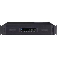
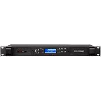

- NETWORK & FIREWALL OVERVIEW....12
- LAKE CONTROLLER TUTORIAL ......27
- HOME MENU REFERENCE....62
- EQ/LEVELS MENU REFERENCE 65
- SYSTEM STORE RECALL MENU REFERENCE.... 114
- MODULES MENU REFERENCE....123
- MODULE FILE TYPES & LAKE LOADLIBRARY™ 171
- GROUPS MENU REFERENCE....186
- SOLO/MUTE MENU REFERENCE 192
- ICON CONTROL MENU REFERENCE....194
- USER PREFERENCES MENU REFERENCE 195
- PAGES MENU REFERENCE....200
- NETWORK MENU REFERENCE....203
- COMMUNICATION AND SYNCHRONIZATION ....208
- FAULTS AND WARNINGS....214
- ANALYZER PLUG-IN....216
- DESIGNER MODE MENU REFERENCE....229
- LAKE-ENABLED AMPLIFIER REFERENCE 257
- LM SERIES REFERENCE AND OPERATION....275
- MY8-LAKE REFERENCE AND OPERATION 281
- GLOBAL EVENTS AND CONTROL....287
- KEYBOARD SHORTCUTS....297
- EXTERNAL CONTROL INTERFACES ....303
- COMMAND LINE OPTIONS 305
- FIRMWARE UPDATE....308
- PRESET MANAGER....313
- IP ADDRESS REFERENCE 324
- CORPORATE INFORMATION 326
- WELCOME
- 1.1 IMPORTANT INFORMATION
- 1.2 INTRODUCTION
- 1.3 CONTROLLER OVERVIEW
- 1.4 MANUAL OVERVIEW
- SOFTWARE INSTALLATION
- 2.1 COMPUTER REQUIREMENTS
- 2.1.1 GENERAL PC REQUIREMENTS
- 2.1.2 RECOMMENDED PC SPECIFICATIONS
- 2.1.3 MINIMUM PC SPECIFICATIONS
- 2.1.4 VIDEO CARD SETTINGS
- 2.15 TABLET PC AND LAPTOP POWER SETTINGS
- 2.1.6 TABLET PC INPUT PANEL SETTINGS
- 2.2 LAKE CONTROLLER INSTALLATION
- 2.2.1 FIRST TIME LAKE CONTROLLER INSTALLATION
- 2.2.2 OVERWRITING EXISTING LAKE CONTROLLER INSTALLATION
- 2.2.3 MULTIPLE LAKE CONTROLLER INSTALLATIONS
- 2.3 MOVING USER FILES BETWEEN INSTALLATIONS
- NETWORK & FIREWALL OVERVIEW
- 3.1 ETHERNET OVERVIEW
- 3.2 FIREWALL CONFIGURATION
- 3.2.1 OVERVIEW
- 3.2.2 WINDOWS 7 SPECIFIC
- 3.3 IP ADDRESS CONFIGURATION
- 3.4 WIRED NETWORK SETUP
- 3.4.1 OVERVIEW
- 3.4.2 VERIFYING WIRED CONTROLLER AND DEVICE COMMUNICATION
- 3.5 WIRELESS NETWORK SETUP
- 3.5.1 OVERVIEW
- 3.5.2 CONFIGURING THE TABLET PC FOR WIRELESS NETWORKING
- 3.5.3 CONFIRMING WIRELESS OPERATION OF THE LAKE CONTROLLER
- 3.6 DANTE AND AES67 DIGITAL AUDIO NETWORKING
- 3.6.1 DANTE CONTROLLER COMPATIBILITY
- 3.6.2 DUAL REDUNDANT NETWORK CONFIGURATION
- 3.6.3 USING DANTE WITH WIRELESS DATA CONTROL OR LOW-BANDWIDTH DEVICES
- 3.6.4 DANTE WITH QUALITY OF SERVICE ETHERNET SWITCHES
- 3.6.5 RECOMMENDED NETWORK TOPOLOGIES WHEN USING DANTE
- LAKE CONTROLLER TUTORIAL
- 4.1 STARTING THE LAKE CONTROLLER
- 4.2 OVERVIEW OF MAIN PAGE COMPONENTS
- 4.2.1 BUTTON BAR INTERFACE
- 4.2.2 HELP AND STATUS MESSAGES
- 4.2.3 PAGE TABS
- 4.2.4 GLOBAL INPUT ROUTER PRIORITY CONTROL
- 4.2.5 MINIMIZING THE LAKE CONTROLLER
- 4.3 MODULES AND FRAMES
- 4.3.1 OVERVIEW
- 4.3.2 MODULE ICONS
- 4.3.3 SELECTING AND MOVING ICONS
- 4.3.4 LABELING FRAMES AND MODULES
- 4.3.5 I/O CONFIG
- 4.3.6 DANTE
- 4.3.7 LEVELS AND METERS
- 4.3.7.1 ADJUSTING LEVELS
- 4.3.72 METERING
- 4.4 EQUALIZATION
- 4.4.1 EQ OVERLAY STORE/RECALL
- 4.4.2 GRAPHIC EQ
- TAP GRAPHIC EQ
- 4.4.3 IDEAL GRAPHIC EQ TM
- 4.4.4 EQ OVERLAYS
- 4.4.5 PARAMETRIC EQ
- 4.4.6 MESA FILTER
- 4.5 CROSSOVERS
- 4.6 GROUPS
- 4.6.6.1 ASSIGNING MODULES TO A GROUP
- 4.7 LAKE CONTROLLER FILE TYPES
- 4.7.1 BASE CONFIGURATION FILES
- 4.7.2 SINGLE MODULE FILE
- 4.7.3 SYSTEM CONFIGURATION FILE
- 4.7.4 STORING A SYSTEM CONFIGURATION
- 4.7.5 STORING A SINGLE MODULE FILE
- HOME MENU REFERENCE
- 5.1 MAIN SCREEN HOME MENU
- 5.2 ACCESSING EQ/LEVELS FROM HOME
- EQ/LEVELS MENU REFERENCE
- 6.1 EQ/LEVELS OVERVIEW
- 6.1.1 GENERAL ACCESS
- 6.1.2 RESTRICTED ACCESS
- 6.1.3 GROUP ADJUSTMENTS
- 6.1.4 DEFAULT SETTINGS
- 6.2 LEVELS
- LEVEL LIMITS
- HIDDEN OUTPUT CHANNELS
- 6.21 GAIN
- 6.2.2 DELAY
- 6.2.3 LIMITERMAX TM
- 6.2.3.1 MAXRMS LEVEL
- 6.2.3.2 MAXRMS CORNER
- 6.2.3.3 MAXRMS ATTACK AND MAXRMS RELEASE
- 6.2.3.4 AUTO TIME CONSTANT
- 6.2.3.5 MAXPEAK LEVEL
- 6.2.3.6 MULTIBAND LIMITER (XP MODULES ONLY)
- 6.2.3.6.1 MULTIBAND LIMITER CONFIGURATION
- 6.2.4 ENABLE MUTE
- 6.2.5 ENABLE POLARITY
- 6.2.6 LABEL CHANNEL
- 6.2.7 METER OPTIONS
- 6.2.7.1 INPUT +4DBU REFERENCE
- 6.2.7.2 PRE LIMITER
- 6.2.7.3 AMPCLIP REFERENCE
- 6.27.4 ASSIGN METERS
- 6.2.7.5 AMPCLIP
- 6.27.6 LEVEL LIMITS
- 6.2.7.7 ADJUST FACTORY
- 6.3 INPUT EQ
- 6.3.1 DEFAULT OVERLAYS
- 6.3.2 EQ OVERLAY PROPERTIES
- 6.3.3 PARAMETRIC EQ SCREEN
- 6.3.4 BAND LEVEL EQ SCREEN
- 6.3.5 GRAPHIC EQ SCREEN
- 6.3.6 INPUT EQ ON-SCREEN FUNCTIONS
- 6.3.6.1 FREQUENCY LOCK
- 6.3.6.2 OVERLAY A/B
- 6.3.6.3 FILTER EDIT
- 6.3.7 INPUT EQ MENU REFERENCE
- 6.3.7.1 EQ OVERLAY PROPERTIES/EQ PREFERENCES
- 6.3.7.2 EQ OVERLAY HIDE/EQ OVERLAY VIEW ONLY
- 6.3.7.3 EQ OVERLAY TYPE
- 6.3.7.4 EQ OVERLAY DELETE
- 6.3.7.5 EQ OVERLAY COPY
- 6.3.7.6 EQ OVERLAY NEW
- 6.3.7.7 EQ OVERLAY PASTE OVER
- 6.3.7.8 EQ OVERLAY LABEL
- 6.3.8 EQ OVERLAY BYPASS/INSERT/COMPARE
- 6.3.8.1 A/B OVERLAY COMPARE
- 6.3.8.2 USING THE A/B BUTTON
- 6.3.8.3 COMPARING EXISTING OVERLAYS
- 6.3.9 EQ OVERLAY STORE/RECALL
- 6.3.9.1 RECALL AS NEW
- 6.3.9.2 RECALL
- 6.3.9.3 STORE
- 6.3.9.4 NEW STORE
- 6.3.9.5 FILE UTILITIES
- OPEN
- READ ONLY
- RENAME
- DELETE
- NEW FOLDER
- 6.3.10 EQ OVERLAY FLAT
- 6.3.11 FILTER BYPASS/FILTER INSERT
- 6.3.12 FILTER FLAT
- 6.3.13 FILTER DELETE
- 6.3.14 ANALYZER TAP TO SEARCH
- 6.3.15 HIGH-PRECISION FILTER ADJUSTMENTS
- 6.4 CROSSOVERS AND HPF/LPF
- 6.4.1 USING THE HIGH-PASS FILTER (HPF ENABLE)
- 6.4.2 FILTER EDIT
- 6.4.3 USING EQ FILTERS ON THE XOVER SCREEN
- 6.4.4 LINEAR PHASE CROSSOVERS
- 6.4.5 XP CROSSOVERS
- 6.4.5.1 FIR IMPORT
- 6.4.6 CROSSOVER FUNCTIONS
- 6.4.6.1 HPF/LPF FUNCTIONS
- 6.4.6.2 CROSSOVER HIDE
- 6.4.6.3 CROSSOVER VIEW ONLY
- 6.4.6.4 EQ PREFERENCES
- 6.4.6.5 CROSSOVER COPY
- 6.4.6.6 CROSSOVER PASTE
- 6.4.7 CROSSOVER SPLIT/CROSSOVER COMBINE/ALIGNMENT DELAY
- 6.4.7.1 CROSSOVER SPLIT
- 6.4.7.2 CROSSOVER COMBINE
- 6.4.7.3 ALIGNMENT DELAY
- 6.4.8 CROSSOVER/HPF/LPF SELECT
- 6.4.8.1 CROSSOVER SELECT
- 6.4.8.2 HPF SELECT
- 6.4.8.3 LPF SELECT
- 6.4.9 HPF SET/LPF SET/CROSSOVER SET/FILTER BYPASS/FILTER INSERT
- 6.4.9.1 HPF SET
- 6.4.9.2 LPF SET
- 6.4.9.3 CROSSOVER SET
- 6.4.9.4 FILTER BYPASS/FILTER INSERT
- 6.4.10 FILTER FLAT
- 6.4.11 FILTER DELETE
- 6.4.12 ANALYZER TAP TO SEARCH
- 6.5 AUXILIARY OUTPUT CHANNELS
- 6.5.1 AUXILIARY OUTPUT MODULE TYPES AND COMBINATIONS
- 6.5.1.1 ONE AUXILIARY OUTPUT
- 6.5.1.2 TWO AUXILIARY OUTPUTS
- 6.5.1.3 THREE AUXILIARY OUTPUTS
- 6.5.1.4 FOUR AUXILIARY OUTPUTS
- 6.5.1.5 FIVE AUXILIARY OUTPUTS
- 6.5.1.6 SIX AUXILIARY OUTPUTS
- 6.5.1.7 CLASSIC 2-WAY + 1-AUXILIARY OUTPUTS
- 6.5.1.8 CLASSIC 3-WAY + 1-AUXILIARY OUTPUTS
- 6.5.1.9 LINEAR PHASE BRICK WALL 2-WAY + 1-AUXILIARY OUTPUTS
- 6.5.2 USING AUXILIARY OUTPUTS
- 6.5.3 ADDING OUTPUT-SPECIFIC EQ
- 6.5.4 HIGH-PASS AND LOW-PASS FILTERS
- 6.5.5 AUXILIARY OUTPUT MENU OPTIONS
- 6.5.5.1 HOME
- 6.5.5.2 EQ/LEVELS EXIT
- 6.5.5.3 AUX OUTPUT FUNCTIONS
- 6.5.5.4 AUX OUTPUT FLAT
- 6.5.5.5 FILTER BYPASS / FILTER INSERT
- 6.5.5.6 FILTER FLAT
- 6.5.5.7 FILTER DELETE
- 6.5.5.8 FILTER EDIT
- 6.5.5.9 ANALYZER READY / ANALYZER UNAVAILABLE
- 6.5.5.10 HOME
- 6.5.5.11 AUX OUTPUT PROPERTIES
- 6.5.5.12 AUX OUTPUT EXIT
- 6.5.5.13 FILTER SELECT
- 6.5.5.14 FILTER SET
- 6.5.5.15 HPF ENABLE
- 6.5.5.16 LPF ENABLE
- 6.5.5.17 AUX OUTPUT COPY
- 6.5.5.18 AUX OUTPUT PASTE
- SYSTEM STORE RECALL MENU REFERENCE
- 7.1 SYSTEM STORE RECALL NAVIGATION
- 7.2 SHORTCUT TO DATA/USER FOLDER
- 7.3 RECALL AS NEW SYSTEM—OPEN
- 7.4 RECALL AS SUBSYSTEM
- 7.5 RECALL COMPARE
- 7.6 RECALL AS VIRTUAL SUB SYSTEM (SS)
- 7.7 STORE SYSTEM
- 7.8 STORE SUBSYSTEM
- 7.9 FILE UTILITIES
- 7.9.1 OPEN
- 7.9.2 READ ONLY
- 7.9.3 RENAME
- 7.9.4 DELETE
- 7.9.5 NEW FOLDER
- 7.10 SYSTEM PRESETS
- 7.10.1 STORING A SYSTEM PRESET IN MULTIPLE DEVICES
- 7.102 RECALLING A SYSTEM PRESET INTO MULTIPLE DEVICES
- 7.10.3 QUICK SYSTEM PRESET RECALL AND COMPARISON
- 7.10.4 STORING OVER AN EXISTING PRESET
- 7.10.5 CLEARING A PRESET LOCATION
- 7.10.6 PRESET MISMATCH
- MODULES MENU REFERENCE
- 8.1 EQ/LEVELS
- 8.2 I/O CONFIG
- 8.2.1 DIGITAL CLOCK CONFIGURATION
- 8.2.1.1 AUTO DETECTION
- 8.2.1.2 MANUAL CONFIG
- 8.2.1.3 DANTE CLOCK (NOT APPLICABLE FOR MY8-LAKE)
- 8.2.1.4 HOST CLOCK (MY8-LAKE ONLY)
- 8.2.2 INPUT CONFIGURATION
- 8.2.2.1 AUTOSELECT
- 8.2.2.2 FORCE
- 8.2.2.3 INPUT SELECTOR SEARCH FILTERS
- 8.2.2.4 INPUT CONFIGURATION DISPLAY DETAILS VIEW
- 8.2.2.5 AES INPUT OPTIONS
- 8.2.2.6 ANALOG INPUT OPTIONS
- 8.2.2.7 DIGITAL GAIN OFFSET
- 8.2.2.8 INPUT ROUTER MUTES
- 8.2.3 GPIO CONFIGURATION (LM SERIES ONLY)
- 8.2.3.1 GPI OPTIONS AND CONFIGURATION (LM SERIES ONLY)
- 8.2.3.2 GPO OPTIONS AND CONFIGURATION (LM SERIES ONLY)
- 8.2.4 BREAKER EMULATION LIMITER (BEL™) - PLM 20000Q, PLM+ AND D SERIES
- 8.2.5 DANTE CONFIGURATION (NOT APPLICABLE FOR MY8-LAKE)
- 8.2.5.1 DEVICE TAB
- PREFERRED CLOCK MASTER
- SAMPLE RATE
- DANTE DEVICE NAME
- DEVICE LATENCY OPTIONS
- 8.2.5.2 RECEIVE TAB
- 8.2.5.3 TRANSMIT TAB
- MULTICAST / UNICAST SETTING
- OUTPUT CHANNEL LABELING
- DANTE DUAL REDUNDANCY
- 8.2.6 ISO-FLOAT STATUS & AES TERMINATION
- 8.2.7 INPUT MIX SUMMARY AND INPUT MIXERS/SWITCHES
- 8.2.7.1 INPUT MIX SUMMARY
- 8.2.7.2 INPUT MIXER
- INPUT +4DBU BUTTON
- AUXILIARY INPUT TOGGLE SWITCH
- SIMPLIFIED VIEW INPUT TOGGLE (MY8-LAKE MESA MODE ONLY)
- 8.2.8 OUTPUT CONFIGURATION
- 8.2.8.1 SOURCE
- 8.2.8.2 DESTINATION
- 8.2.8.3 DESTINATION OUTPUT OPTIONS
- 8.2.8.4 SHOW OUTPUT ROUTING ON MODULE RECALL
- 8.2.8.5 MODULE OUTPUT MIXING (PLM+ AND D SERIES ONLY)
- ANALOG OUTPUT OPTIONS
- AES OUTPUT OPTIONS
- DANTE OUTPUT CONFIGURATION
- DISCONNECTING OUTPUTS FOR OUTPUT TYPE
- BRIDGE MODE CONFIGURATION (LAKE-ENABLED AMPLIFIER ONLY, EXCEPT D 10:4L, D 20:4L AND D 40:4L)
- 8.2.9 LATENCY MATCH
- 8.2.10 TECHNICAL DATA
- 8.2.10.1 PRODUCT/MODEL
- 8.2.10.2 FRONT PANEL ENABLE (D SERIES ONLY)
- 8.2.10.3 DANTE SLAVE ONLY (NOT APPLICABLE FOR MY8-LAKE)
- 8.2.10.4 DUAL REDUNDANCY (NOT APPLICABLE FOR MY8-LAKE)
- 8.2.10.5 IP ADDRESS CONFIG
- 8.2.10.6 IP ADDRESS
- 8.2.10.8 ID
- 8.2.10.9 FIRMWARE
- 8.2.10.10 SERIAL NUMBER
- 8.2.11 INPUT ROUTER MUTES
- 8.2.12 INTERACTIVE SIGNAL PATH BLOCK DIAGRAM
- 8.2.13 INPUT SELECTION (MY8-LAKE IN SIMPLIFIED VIEW ONLY)
- 8.2.14 FRAME CONFIG/SOFT RESET
- 8.3 LABEL & LOCK
- 8.3.1 MODULE LABEL
- 8.3.1.1 DYNAMIC MODULE LABEL
- 8.3.2 FRAME LABEL
- 8.3.3 MODULE AND BASE CONFIGURATION LOCKING
- 8.4 COPY/PASTE/REPLACE
- 8.4.1 COPY
- 8.4.2 PASTE
- 8.4.3 REPLACE FRAME
- 8.4.3.1 REPLACE FRAME RULES AND COMPATIBILITY
- 8.4.4 COMPLETE REPLACE
- 8.4.5 BATCH REPLACE
- 8.4.5.1 ASSIGNING THE VIRTUAL FRAMES TO THE DESTINATION FRAMES
- 8.5 REMOVE
- 8.6 MODULE STORE/RECALL
- 8.6.1 RECALL/OPEN
- 8.6.2 STORE
- 8.6.3 NEW STORE
- 8.6.4 BASE CONFIGURATION
- 8.6.5 FILE UTILITIES
- 8.6.5.1 OPEN
- 8.6.5.2 READ ONLY
- 8.6.5.3 RENAME
- 8.6.5.4 DELETE
- 8.6.5.5 NEW FOLDER
- 8.6.6 FRAME PRESETS
- 8.6.6.1 STORE
- 8.6.6.2 STORE WITH NEW NAME
- 8.6.6.3 CLEAR
- 8.7 ADD PAGE
- 8.8 SUPER MODULES (LM & PLM SERIES ONLY)
- 8.8.1 ASSIGNING SUPER MODULES
- 8.8.2 SUPER MODULE EQ/LEVELS OR MODULE EQ/LEVELS
- 8.8.3 SM ROUTING: I/O CONFIG
- 8.8.4 LABEL FRAME
- 8.8.5 DE-ASSIGNING A SUPER MODULE
- 8.8.6 REMOVE SUPER MODULE
- MODULE FILE TYPES & LAKE LOADLIBRARY™
- 9.1 MODULE TYPES OVERVIEW
- 9.2 SUPPLEMENTARY MODULE DATA
- 9.3 MODULE TYPE ABBREVIATIONS
- 9.4 CLASSIC CROSSOVERS/AUXILIARY OUTPUTS
- 9.4.1 CLASSIC 2-WAY + 1-AUXILIARY OUTPUTS
- 9.4.2 CLASSIC 3-WAY AND 3-AUXILIARY OUTPUTS
- 9.4.3 CLASSIC 3-WAY + 1-AUXILIARY OUTPUTS (WITH CLASSIC 2-WAY/2-AUX)
- 9.4.4 CLASSIC 4-WAY/4-AUX (WITH CLASSIC 2-WAY/2-AUX)
- 9.4.5 CLASSIC 5-WAY/5-AUX (WITH 1-AUXILIARY OUTPUTS)
- 9.4.6 CLASSIC 6-WAY/6-AUXILIARY OUTPUTS
- 9.5 LINEAR PHASE CROSSOVERS
- 9.5.1 LINEAR PHASE 2-WAY (+1-AUXILIARY OUTPUTS)
- 9.5.2 LINEAR PHASE 3-WAY
- 9.5.3 LINEAR PHASE 2-/3-WAY EQ/MAXPEAK COMBINATIONS
- 9.5.4 LINEAR PHASE BRICK WALL 4-WAY
- 9.6 FIR MODULE
- 9.6.1 FIR 1-WAY
- 9.6.2 FIR 2-WAY
- 9.6.3 FIR 3-WAY
- 9.7 XP MODULE [PLM+ AND D SERIES ONLY]
- 9.7.1 XP 1-WAY
- 9.7.2 XP 2-WAY
- 9.7.3 XP 3-WAY
- 9.7.4 XP 4-WAY
- 9.8 MESA EQ MODULE
- 9.9 LAKE LOADLIBRARY
- 9.10 ADDITIONAL INFORMATION
- GROUPS MENU REFERENCE
- 10.1 ADDING A GROUP
- 10.2 EQ/LEVELS
- 10.3 ASSIGN
- 10.3.1 ASSIGN ONE-BY-ONE
- 10.3.2 ASSIGN BY MULTI-SELECT
- 10.3.3 ASSIGN BY COPY/PASTE
- 10.3.4 KEEP GROUP ASSIGNMENT ON MODULE RECALL
- 10.4 LABEL
- 10.5 COPY/PASTE
- 10.5.1 COPY
- 10.5.2 PASTE
- 10.6 REMOVE
- 10.7 GANG
- 10.7.1 GANG XOVER/AUX OR GANG HPF/LPF
- 10.8 ADD PAGE
- 10.9 DISCOVERING MODULE GROUP ASSIGNMENTS
- SOLO/MUTE MENU REFERENCE
- 11.1 EQ/LEVELS
- 11.2 SOLO/MUTE ENABLE
- 11.3 PILE
- 11.4 ALL MUTE
- ICON CONTROL MENU REFERENCE
- 12.1 METERS ON/OFF
- 12.2 FAST METERS
- 12.3 ICON SMALL/NORMAL/MEDIUM/LARGE
- USER PREFERENCES MENU REFERENCE
- 13.1 CONTEXTS
- 13.2 DELAY UNITS
- 13.3 DESIGNER FUNCTIONS
- 13.3.1 CHANGE PASSWORD
- 13.3.2 DESIGNER MODE
- 13.3.3 GLOBAL ACCESS
- 13.3.4 MODULE OUTPUT MIXING (PLM+ AND D SERIES AMPLIFIERS ONLY)
- 13.4 KEYBOARD SHORTCUTS
- 13.5 ABOUT
- 13.6 GRAPHICS
- 13.6.1 DISPLAY MODE
- 13.6.2 AUTO ICON ARRANGE
- 13.6.3 SCREEN CAPTURE
- 13.6.4 ANIMATE
- 13.6.5 DAYLIGHT MODE
- 13.7 SHOW MODE
- PAGES MENU REFERENCE
- 14.1 CUT ICON
- 14.2 COPY ICON
- 14.3 PASTE ICON
- 14.4 PAGE LABEL
- 14.4.1 UNUSED
- UNUSED2 ETC
- 14.5 PAGE DELETE
- 14.6 PAGE ADD
- 14.7 PAGE HIDE
- 14.8 SCROLLING PAGES
- NETWORK MENU REFERENCE
- 15.1 NETWORK
- 15.2 MULTIPLE CONTROLLERS
- 15.2.1 OVERVIEW AND MENU OPTIONS
- 15.2.1.1 MULTI CONT ENABLE
- 15.2.1.2 CONFIRMATION REQUIRED
- 15.2.1.3 ANALYZER ENABLE
- 15.2.2 PRIMARY AND SECONDARY CONTROLLERS
- 15.2.3 RESTRICTED FUNCTIONALITY
- 15.2.4 USING THE ANALYZER WITH MULTIPLE LAKE CONTROLLERS
- 15.3 WORKING OFFLINE
- 15.3.1 VIRTUAL FRAMES
- 15.3.2 REPLACING VIRTUAL FRAMES WITH AN ONLINE DEVICE
- COMMUNICATION AND SYNCHRONIZATION
- 16.1 OFFLINE MODULES
- 16.2 COMMUNICATION/NETWORK ERRORS
- 16.3 SYNCHRONIZATION
- 16.3.1 RESYNC PROCESS
- 16.3.2 OUT OF SYNC
- 16.3.3 UPDATING ALL DEVICES WITH COMPUTER SETTINGS
- 16.3.4 UPDATING THE CONTROLLER WITH DEVICE SETTINGS
- 16.3.5 SYNCHRONIZING THE LAKE CONTROLLER AND DEVICES
- 16.3.6 AUDIBLE CHANGES WHEN SYNCHRONIZING
- FAULTS AND WARNINGS
- 17.1 FAULTS AND WARNINGS INDICATION
- ANALYZER PLUG-IN
- 18.1 OVERVIEW
- 18.2 SYSTEM REQUIREMENTS
- 18.3 ANALYZER PLUG-IN QUICK START GUIDE
- 18.4 FUNCTION REFERENCE
- 18.4.1 GLOBAL CONTROL FUNCTIONS
- 18.4.1.1 PAUSE
- 18.4.1.2 SIGNAL GENERATOR
- 18.4.1.3 MEASUREMENT SELECTION
- 18.4.2 SPECTRUM RTA MEASUREMENT MODE
- 18.4.2.1 AVERAGES
- 18.4.2.2 AMPLITUDE RANGE
- MOVE PRIMARY UP
- MOVE PRIMARY DOWN
- ZOOM PRIMARY IN
- ZOOM PRIMARY OUT
- 18.4.2.3 BANDING
- 18.4.3 SPECTROGRAPH MEASUREMENT MODE
- 18.4.3.1 COLORMAP RANGE
- 18.4.3.2 SPEED
- 18.4.3.3 SPECTROGRAPH PROPERTIES
- 18.4.4 TRANSFER FUNCTION MEASUREMENT MODE
- 18.4.4.1 RESEED AVG
- 18.4.4.2 DELAY CONTROLS
- 18.4.4.3 TRANSFER PROPERTIES
- 18.4.4.4 AVERAGES
- 18.4.4.5 AMPLITUDE RANGE
- 18.4.4.6 SMOOTHING
- 18.4.4.7 COHERENCE
- 18.4.4.8 PHASE
- 18.4.4.9 PHASE PROPERTIES
- PHASE NORMAL / PHASE ALTERNATE
- 18.4.4.10 INVERT
- DESIGNER MODE MENU REFERENCE
- 19.1 DESIGNER MODE BASICS
- 19.1.1 SECURITY LEVELS
- 19.1.1.1 GLOBAL
- 19.1.1.2 MODULE
- 19.1.1.3 BASE CONFIGURATION
- 19.1.2 DESIGNER MODE
- 19.1.2.1 PASSWORD PROTECTION OF DESIGNER MODE
- 19.1.2.2 SIMPLE DESIGNER MODE SYSTEM SECURITY
- 19.1.3 DESIGNING AND PROTECTING A LAKE CONTROLLER SYSTEM
- 19.1.3.1 SYSTEM SETUP FOR DESIGNER MODE TUTORIAL
- 19.2 DESIGNER MODE SECURITY
- 19.2.1 SECURITY FOR THE BASE CONFIGURATION
- 19.2.1.1 CROSSOVER AND OUTPUT EQ
- 19.2.1.2 INPUT EQ (PEQ, BLEQ & GEO)
- 19.2.1.3 LEVELS
- 19.2.1.4 BASE CONFIGURATION TUTORIAL
- 19.2.1.5 SUMMARY
- 19.2.2 SECURITY FOR MODULE FUNCTIONS
- 19.2.2.1 MODULE TUTORIAL
- 19.2.2.2 SUMMARY
- 19.2.3 SECURITY FOR GROUP FUNCTIONS
- 19.2.3.1 GROUP TUTORIAL
- 19.2.3.2 SUMMARY
- 19.2.4 SECURITY FOR GLOBAL ACCESS FUNCTIONS
- 19.2.4.1 GLOBAL ACCESS TUTORIAL
- 19.2.4.2 SUMMARY
- 19.3 FUNCTIONAL REFERENCE GUIDE
- 19.3.1 XOVER/AUX/HPF/LPF FUNCTIONS
- 19.3.1.1 SET INDIVIDUAL XOVER SCREENS TO HIDE/VIEW ONLY
- 19.3.1.2 SET ALL XOVER/AUX OR HPF/LPF SCREENS TO HIDE/VIEW ONLY
- 19.3.1.3 ALL PASS FILTERS
- 19.3.2 EQ FUNCTIONS
- 19.3.2.1 SET HIDE/VIEW ONLY STATUS FOR AN INDIVIDUAL EQ OVERLAY
- 19.3.2.2 SET HIDE/VIEW ONLY STATUS FOR ALL EQ OVERLAYS
- 19.3.3 LEVELS FUNCTIONS
- 19.3.3.1 ADJUST FACTORY LEVELS
- 19.3.3.2 RESTRICT LEVEL ADJUSTMENTS
- 19.3.3.3 DISABLE LEVEL ADJUSTMENTS
- 19.3.3.4 DISABLE ACCESS TO A LEVELS FUNCTION
- 19.3.3.5 DISABLE/ENABLE UNUSED OUTPUT CHANNELS
- 19.3.3.6 SET HIDE/VIEW ONLY STATUS FOR ALL LEVELS SCREENS
- 19.3.4 ADDITIONAL DESIGNER MODE FUNCTIONS
- 19.3.4.1 SWITCH BETWEEN DESIGNER MODE AND USER MODE
- 19.3.4.2 LOCK AND PASSWORD-PROTECT A MODULE OR BASE CONFIGURATION
- 19.3.4.3 UNLOCK A LOCKED MODULE OR BASE CONFIGURATION
- 19.3.4.4 CREATING DESCRIPTIONS/ASSIGNING GRAPHICS FOR MODULE FILES
- 19.4 DESIGNER WORKSHEETS
- 19.4.1 OVERVIEW
- 19.4.2 WORKSHEET NAVIGATION AND DATA ENTRY
- 19.4.2.1 EXTERNAL KEYBOARD ENTRY
- 19.4.2.2 ON-SCREEN KEYBOARD ENTRY
- 19.4.3 XOVER/AUX: DESIGN (LOUDSPEAKER MODULES ONLY)
- 19.4.3.1 HPF AND LPF TYPES
- 19.4.3.2 CLASSIC CROSSOVER TYPES
- 19.4.3.3 LINEAR PHASE CROSSOVER TYPES
- 19.4.3.4 LINEAR PHASE ALIGNMENT DELAY
- 19.4.3.5 OUTPUT EQ TYPES
- 19.4.3.6 FIR IMPORT/EXPORT (XP MODULES ONLY)
- 19.4.4 HPF/LPF - DESIGN (MESA EQ ONLY)
- 19.4.5 LEVELS - DESIGN
- 19.4.6 PEQ - DESIGN
- 19.4.7 GEQ - DESIGN
- 19.4.8 BLEQ - DESIGN
- 19.4.9 LOCKED MODULES/HIDDEN/VIEW ONLY DATA
- LAKE-ENABLED AMPLIFIER REFERENCE
- 20.1 SIGNAL FLOW
- 20.2 MONITORING & CONTROL
- 20.3 LAKE LOADLIBRARY™
- 20.4 LOADSMART™
- 20.5 NAVIGATION
- 20.5.1 ACCESSING MODULE VIEW
- 20.5.2 ACCESSING GLOBAL VIEW
- 20.6 STATUS TAB
- 20.6.1 ATTENUATION
- 20.6.2 MUTE 2
- 20.6.3 PHASE REVERSE ③
- 20.6.4 METERS 4
- 20.6.5 SPEAKER DATA BLOCK 5
- 20.6.6 POWER OUTPUT DATA BLOCK 6
- 20.6.7 MUTE AND POLARITY ENABLE
- 20.7 HISTORY TAB
- 20.7.1 SELECT CURVE
- 20.7.2 SELECT DIMENSION
- 20.7.3 CHANNELS
- 20.8 EVENTS TAB
- 20.9 LOADSMART TAB
- 20.9.1 NUMBER OF CABINETS
- 20.9.2 CABLE RESISTANCE
- 20.9.2.1 CALCULATOR
- 20.9.2.2 AMBIENT TEMPERATURE
- 20.9.3 FINGERPRINT LABEL
- 20.9.4 VERIFY
- 20.9.5 SETTINGS
- 20.9.6 LOADSMART RESULTS
- 20.9.6.1 LOAD TYPE VERIFICATION
- 20.9.6.2 CABINET COUNT VERIFICATION
- 20.9.6.3 VOICE COIL TEMPERATURE
- 20.10 OUTPUT TAB
- 20.10.1 AMPLIFIER GAIN
- 20.10.2 INTER-SAMPLE VOLTAGE PEAK LIMITER (ISVPL) THRESHOLD
- 20.10.2.1 RATIONAL POWER MANAGEMENT (PLM+ AND D SERIES ONLY)
- AUTO RPM
- CUSTOM RPM
- 20.10.3 ISVPL PROFILE
- 20.10.4 AMPLIFIER CLIP LEVEL
- 20.10.5 AMPLIFIER GAIN AND ISVPL LEVEL LIMITS
- 20.11 POWER
- 20.11.1 POWER CONTROL
- 20.11.2 AUTO POWER DOWN (PLM+ AND D SERIES ONLY)
- 20.11.3 ADAPTIVE RAIL CONTROL (D SERIES D10:4L, D20:4L & D40:4L ONLY)
- LM SERIES REFERENCE AND OPERATION
- 21.1 PASS-THRU INPUT ROUTER FUNCTIONALITY
- 21.1.1 OVERVIEW
- 21.1.2 CONFIGURING PASS-THRU INPUT TO OUTPUT VIA INPUT ROUTER
- 21.2 GPIO CONFIGURATION
- 21.3 REMOTE POWER CONTROL & EVENT LOGS
- 21.3.1 NAVIGATION
- 21.3.1.1 ACCESSING EVENTS AND CONTROL (MODULE VIEW)
- 21.3.1.2 ACCESSING EVENTS & CONTROL (SUPER MODULE VIEW)
- 21.3.1.3 ACCESSING EVENTS & CONTROL (GLOBAL VIEW)
- MY8-LAKE REFERENCE AND OPERATION
- 22.1 SIGNAL FLOW
- 22.1.1 MESA CONFIGURATION SIGNAL FLOW DIAGRAM
- 22.1.2 CONTOUR CONFIGURATION SIGNAL FLOW DIAGRAM
- 22.1.3 CONTOUR/MESA CONFIGURATION SIGNAL FLOW DIAGRAM
- 22.2 OPERATION MODE
- 22.3 HOST ANALOG OUTPUT REFERENCE CONFIGURATION
- 22.4 I/O CONFIGURATION VIEW MODE OPTIONS
- 22.4.1 SIMPLIFIED VIEW (NOT YET IMPLEMENTED)
- 22.4.2 CLASSIC VIEW (ALL DEVICES AND CONFIGURATIONS)
- 22.4.3 CHANGING BETWEEN SIMPLIFIED VIEW AND CLASSIC VIEW
- GLOBAL EVENTS AND CONTROL
- 23.1 GLOBAL EVENTS TAB
- 23.1.1 LOG ENTRIES
- 23.1.2 SORTING OPTIONS
- 23.1.3 FILTERING OPTIONS
- 23.1.3.1 SEVERITY
- 23.1.3.2 SOURCE
- 23.1.3.3 TIME
- 23.2 GLOBAL CONTROL TAB
- 23.2.1 GLOBAL POWER CONTROL
- 23.2.2 GLOBAL POWER CHANNEL MUTE CONTROL
- 23.2.3 GLOBAL TEMPERATURE
- 23.2.4 GLOBAL LOADSMART
- 23.2.5 GLOBAL DUAL REDUNDANCY CONTROL
- 23.2.6 GLOBAL DANTE ENABLED CONTROL
- 23.2.7 GLOBAL DANTE TRANSMIT ENABLED CONTROL
- 23.2.8 GLOBAL AES67 ENABLE CONTROL (PLM+ AND D SERIES ONLY)
- 23.2.9 GLOBAL AUTO POWER DOWN CONTROL (PLM+ AND D SERIES ONLY)
- 23.2.10 SHOW GLOBAL INPUT ROUTER PRIORITY CONTROL
- 23.2.11 SHOW GLOBAL STATUS INDICATOR
- 23.2.12 GLOBAL IP CONFIGURATION
- 23.3 ARRAY OPT (XP MODULES ONLY)
- 23.3.1 SYSTEM INFORMATION
- 23.3.2 ARRAY OPTIMIZATION CONTROL
- 23.4 LOG FILES
- 23.4.1 STATISTICAL LOG FILES
- 23.4.2 EVENT LOG
- KEYBOARD SHORTCUTS
- 24.1 ENABLING/DISABLING KEYBOARD SHORTCUTS
- 24.2 GENERAL KEYBOARD SHORTCUTS
- 24.3 BUTTON BAR SHORTCUTS
- 24.3.1 CONTEXT SWITCHING
- 24.3.2 MAIN NAVIGATION/FUNCTION BUTTONS
- 24.3.3 UNDO/REDO
- 24.3.4 SHORTCUT COMBINATION KEYS
- 24.4 EQ, LEVELS, XOVER, AND AUX SCREEN SHORTCUTS
- 24.4.1 GEQ OVERLAY SHORTCUTS
- 24.4.2 PEQ OVERLAY SHORTCUTS
- 24.4.3 BLEQ OVERLAY SHORTCUTS
- 24.4.4 XOVER/AUX SCREEN SHORTCUTS
- 24.4.5 LEVELS SCREEN SHORTCUTS
- EXTERNAL CONTROL INTERFACES
- 25.1 GPIO (LM SERIES ONLY)
- 25.2 AMX® AND CRESTRON® CONTROL
- 25.2.1 DLM PROTOCOL
- 25.3 Q-SYS PLUGIN
- COMMAND LINE OPTIONS
- 26.1 OVERVIEW
- 26.2 REFERENCE
- FIRMWARE UPDATE
- 27.1 BACKUP SYSTEM CONFIGURATION AND PRESETS
- 27.2 UPDATING FIRMWARE
- 27.3 INCOMPATIBLE FIRMWARE NOTIFICATION IN LAKE CONTROLLER
- 27.4 REMOTE POWER CYCLE
- PRESET MANAGER
- 28.1 STARTING THE LAKE PRESET MANAGER
- 28.2 SCREEN LAYOUT
- 28.2.1 MAIN AREA
- 28.2.2 BUTTON BAR INTERFACE
- 28.3 WORKING WITH FRAMES
- 28.3.1 SELECTING A FRAME
- 28.3.1.1 RENAME FRAME [F5]
- 2 SELECT MULTIPLE [F6]
- 28.3.1.3 SET FRAME PASSWORD/CHANGE PASSWORD [F7]
- 28.3.2 STORING A PRESET
- 28.3.2.1 RECALL PRESET [F1]
- 28.3.2.2 STORE PRESET [F2]
- 28.3.2.3 CLEAR PRESET [F4]
- 28.3.2.4 RENAME PRESET [F5]
- 28.3.2.5 SELECT MULTIPLE [F6]
- 28.3.2.6 SET FRAME PASSWORD/CHANGE PASSWORD [F7]
- 28.3.2.7 LOCK PRESET/UNLOCK PRESET [F8]
- 28.3.2.8 EXCLUDE/INCLUDE LABELS [F9]
- 28.4 WORKING WITH BANK FILES
- 28.4.1 CREATING A NEW BANK FILE
- 28.4.2 BANK FILE / FOLDER FUNCTIONS
- 28.4.2.1 OPEN [F1]
- 28.4.2.2 NEW FOLDER [F2]
- 28.4.2.3 DELETE [F4]
- 28.4.2.4 RENAME [F5]
- 28.4.2.5 SELECT MULTIPLE [F6]
- 28.4.2.6 SET BANK PASSWORD/CHANGE PASSWORD [F7]
- 28.4.3 PRESET FUNCTIONS
- 28.4.3.1 CLEAR PRESET [F4]
- 28.4.3.2 RENAME PRESET [F5]
- 28.4.3.3 SELECT MULTIPLE [F6]
- 28.4.3.4 SET BANK PASSWORD/CHANGE PASSWORD [F7]
- 28.4.3.5 LOCK / UNLOCK PRESET [F8]
- 28.4.3.6 EXCLUDE / INCLUDE LABELS [F8]
- 28.4.4 TRANSFERRING PRESETS BETWEEN BANK FILES AND DEVICES
- 28.4.5 BANK FILENAME EXTENSIONS
- 28.5 COMMON FUNCTIONALITY
- 28.5.1 EXIT [F10]
- IP ADDRESS REFERENCE
- 29.1 NETWORK ESSENTIALS
- 29.2 FACTORY RESET CONFIGURATION
- CLASS RANGE
- CORPORATE INFORMATION
- 30.1 CONTACT DETAILS
- 30.2 TRADEMARKS
Brand : Lab Gruppen
Model : PLM 5K44
Category : Receiver