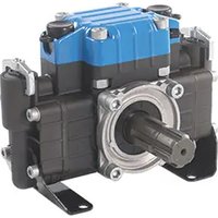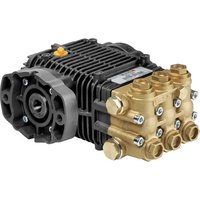
TW HYDR - Pump Comet - Free user manual and instructions
Find the device manual for free TW HYDR Comet in PDF.


User questions about TW HYDR Comet
0 question about this device. Answer the ones you know or ask your own.
Ask a new question about this device
Download the instructions for your Pump in PDF format for free! Find your manual TW HYDR - Comet and take your electronic device back in hand. On this page are published all the documents necessary for the use of your device. TW HYDR by Comet.
USER MANUAL TW HYDR Comet
(IT) POMPE ALTA PRESSIONE
(EN) HIGH PRESSURE PUMPS
(FR) POMPES HAUTE PRESSION
(DE) HOCHDRUCKPUMPEN
(RU) НАСОСЫ ВЫСОКОГО ДАВЛЕНИЯ
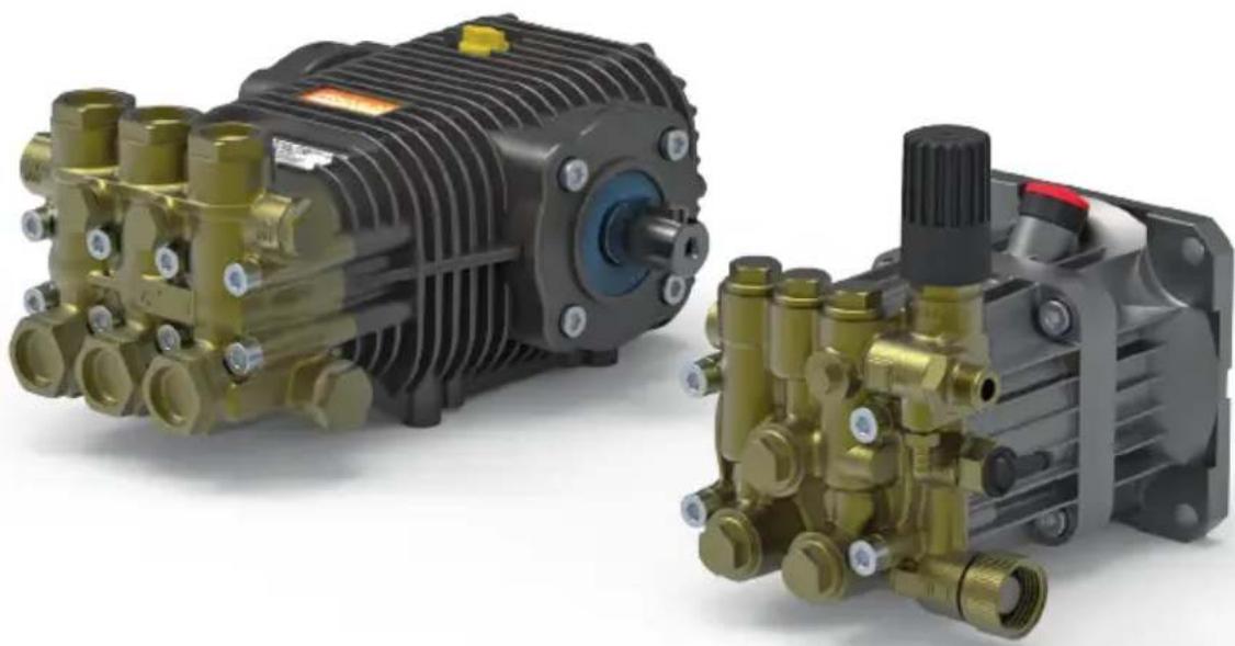
natural_image
Two brass industrial pumps with internal components, shown from different angles (no visible text or labels)ITALIANO
IT
ENGLISH
EN
FRANÇAIS
FR
ESPAÑOL
ES
DEUTSCH
DE
(EN)·WARNING.Read the instructions before use and assembly
natural_image
Close-up of a brass and black industrial pressure pump assembly (no visible text or symbols)BW - AW LW - ZW
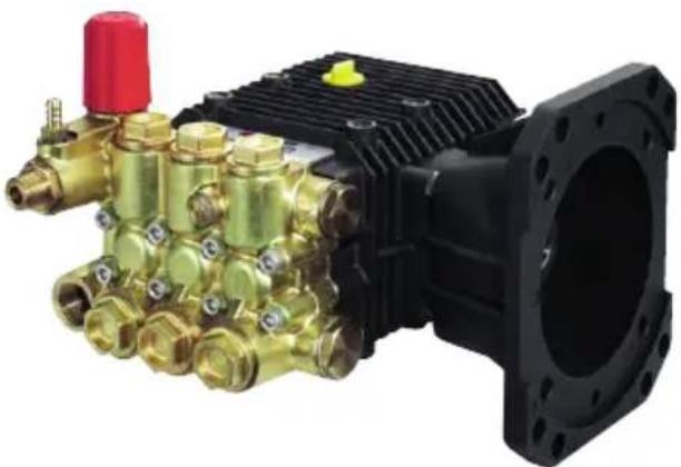
natural_image
Close-up of a mechanical pressure pump assembly with brass fittings and a black housing (no visible text or symbols)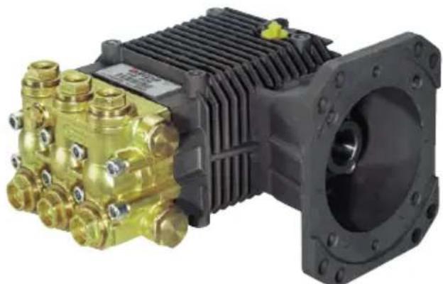
natural_image
Exterior view of a mechanical pump assembly with brass components and black housing (no visible text or symbols)FW - FW2 HW
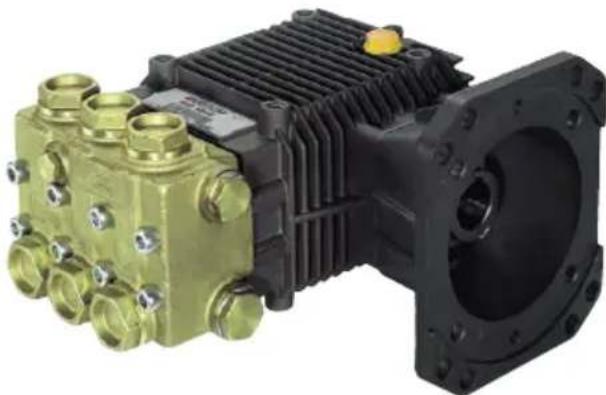
natural_image
Close-up of a mechanical pump assembly with brass housing and black housing (no visible text or symbols)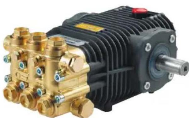
natural_image
Close-up of a brass and black industrial pressure pump with no visible text or symbolsRW TW - SW
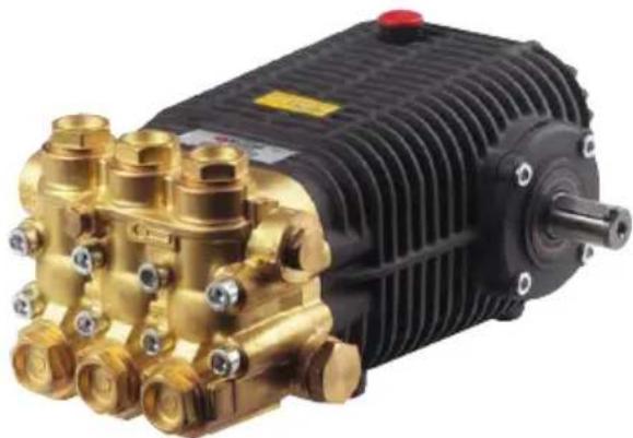
natural_image
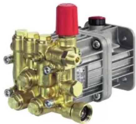
Close-up of a brass and black industrial pressure pump with cooling fins and a red valve (no visible text or symbols)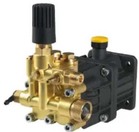
natural_image
Close-up of a brass and black industrial pressure pump assembly (no visible text or symbols)BX AX
natural_image
Close-up of a brass mechanical pump assembly with red and black components (no visible text or symbols)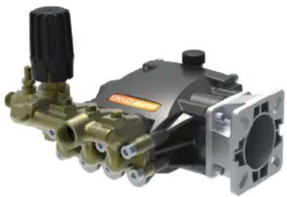
natural_image
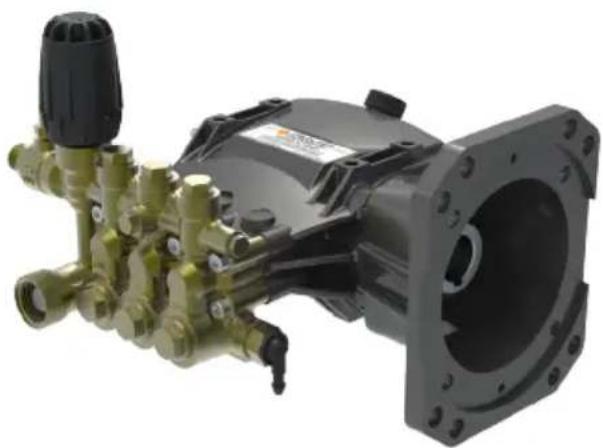
Industrial pressure pump assembly with brass and black components (no visible text or symbols)DW EW
natural_image
Mechanical component with brass and black fittings, no visible text or symbols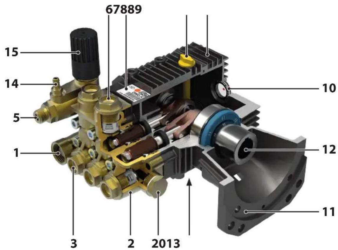
text_image
67889 15 14 5 1 3 2 2013 10 12 11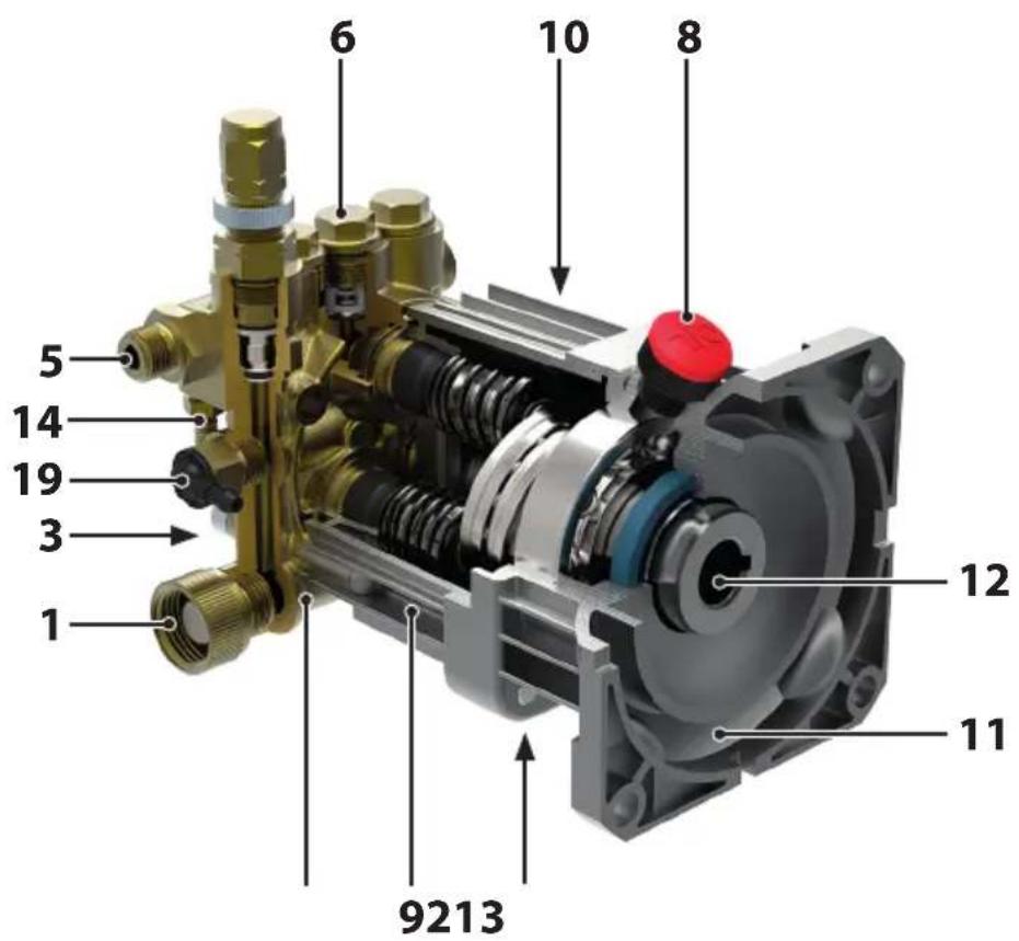
text_image
1 3 5 14 19 6 10 8 12 11 9213
text_image
67889 5 10 4 3 118132 12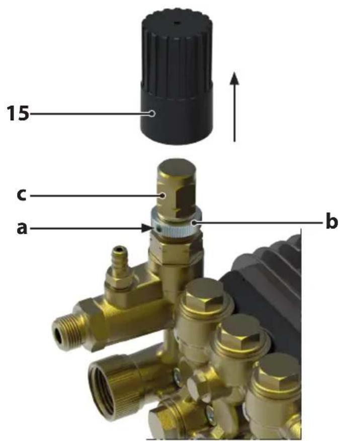
text_image
15 c a b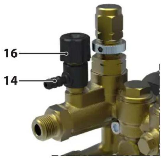
text_image
16 14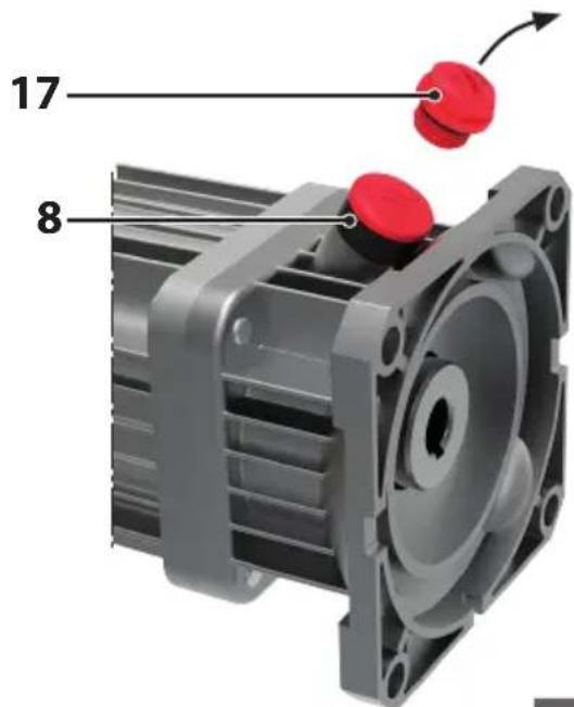
text_image
17 85
text_image
HGE A B C F D6
PREMESSA
| Mobil Delvac MX 15W-40 | Total Rubia TIR 7400 15W-40 |
| Shell Rimula R4 15W-40 | ENI i-Sigma performance E7 15W-40 |
| Gazprom-Neft super oil GTD 15W-40 | Castrol GTX Professional 15W-40 |
This manual consists of two distinct parts.
The first is intended for both the end user and the Skilled Technician and contains the pump operation and maintenance instructions; the second is dedicated to the Skilled Technician only and provides instructions for the correct integration of the pump in the end machine and for special maintenance.
By Skilled Technician is meant:
- the Manufacturer of the machine (e.g., high pressure cleaner) in which the pump is integrated (from now on, when reference is made to “machine in which the pump is integrated”, this may also refer to “system in which the pump is integrated”, such as, for example, in the case of a pumping station);
- a person, normally belonging to the after-sales centre, specifically trained and authorised to perform special maintenance jobs and repairs on the pump and on the machine in which this is integrated. It should be remembered that jobs on the electrical parts must be performed by a Skilled Technician who is also a Professional Electrician, meaning a person professionally qualified and trained to check, install and repair electrical apparatus in a “workmanlike” manner and in accordance with the laws applicable in the country where the machine integrating the pump is installed.
PART ONE
GENERAL INFORMATION
Carefully read this manual and the manual of the machine in which the pump is integrated: always carefully comply with the instructions contained in them.
Special care must be given to reading the parts of the text marked by the symbol:

WARNING
inasmuch as these contain important safety instructions concerning pump operation.
The Manufacturer disclaims all liability relating to damage caused by:
- failure to abide by the contents of this manual and the manual of the machine in which the pump is integrated;
- the pump being used in ways other than those indicated in the "INTENDED USE" paragraph;
- the pump being used in ways contrary to applicable laws on safety and prevention of work accidents;
- tampering with the safety devices and with max operating pressure limitation;
- incorrect assembly and installation;
- incorrect maintenance;
- changes made or jobs done on the pump without the permission of the Manufacturer;
- use of non-original spare parts or which are not suitable for the pump model;
• repairs not performed by a Skilled Technician.
USING AND LOOKING AFTER THE MANUAL

WARNING
- This manual completes that of the machine in which the pump is integrated: read all the manuals carefully.
The manual must be deemed an integral part of the pump and must be looked after for future reference and kept in a protected place where it can easily be referred to in case of need.
The manual contains safety precautions for the operator and those surrounding him/her and for the protection of the environment.
In case of deterioration or loss, a new copy must be requested from the Manufacturer or from a Skilled Technician.
In the event of the machine in which the pump is integrated being transferred to another user, please also include this manual.
The Manufacturer reserves the right to make all the amendments required to update and correct this publication without prior notice.
SYMBOLS
The symbol:

marking certain parts of the text indicates a likely chance of injury to persons unless the relative prescriptions and indications are followed.
The symbol:
CAUTION
marking certain parts of the text indicates the possibility of damaging the pump unless the relative instructions are followed.
SPECIFICATIONS AND TECHNICAL DATA
The first two letters of the pump model code (LW, FW, ZW, etc.) allow identifying the specific model (an exception is represented by the second series of FW pumps, which is indicated by FW2).
| AX BX BW AW DW EW LW | ||||||||
| MECHANICAL CONNECTIONMax power input (1) kWCV | 0,3÷6,30,4÷8,6 | 0,54÷4,20,7÷5,7 | 2,0÷4,32,7÷5,8 | 4,7÷7,56,4÷10,2 | 3,7÷6,45,0÷8,7 | 7,3÷8,29,9÷11,1 | 0,2÷4,00,3÷5,4 | |
| Max rotation speed | See following table | |||||||
| PUMP OILQuantity in weight kg - lb | 1 (2) | 2 (3) | 1 (2) | |||||
| 0,16/0,350 | 10/0,220,25 | /0,550,25 | /0,550,25/0 | ,550,3/0,66 | 0,28/0,62 | |||
| Quantity in volume I - USgal | 0,18/0,050 | 11/0,030,28 | /0,070,28 | /0,070,28/0 | ,070,33/0,09 | 0,32/0,08 | ||
| HYDRAULIC CONNECTIONMax water temperature (4) °C - °F | 60/140 | |||||||
| Min water temperature °C - °F | 5/41 | |||||||
| Maximum supply water pressure bar | 8 | |||||||
| Minimum supply water pressure (<= 1750 RPM) bar | -0,1 | -0,1 | ||||||
| Minimum supply water pressure (> 1750 RPM) bar | -0,05 | 1,5 | 1 | -0,05 | ||||
| Min water flow rate | 1,3 x max flow rate | |||||||
| PERFORMANCE - WEIGHTMax flow rate | See following table | |||||||
| Max pressure | See following table | |||||||
| Max level of sound pressure - uncertainty | 79 dB(A)1 dB(A) | |||||||
| Max weight kg - lb | 6,0/13,2 | 4,7/10,4 | 6,0/13,2 | 6,5/14,3 | 5,5/12,1 | 6,6/14,5 | 7,2/15,9 | |
| ZW FW | FW2 HW RW SW TW | ||||||
| MECHANICAL CONNECTIONMax power input(1)kWCV | 3,7÷8,75,0÷11,8 | 3,7÷7,75,0÷10,5 | 2,0÷10,52,7÷14,3 | 7,1÷11,59,7÷15,6 | 4,4÷13,36,0÷18,1 | 7,9÷10,610,7÷14,4 | 7,5÷24,710,2÷33,6 |
| Max rotation speed | See following table | ||||||
| PUMP OILQuantity in weight kg - lb | 1 (2) | 2 (3) | |||||
| 0,36 - 0,79 | 0,50 - 1,10,50 | -1,10,50 - 1 | 10,70 - 1,50 | ,97 - 2,10,97 | -2,1 | ||
| Quantity in volume l - USgal | 0,41 - 0,11 | 0,56 - 0,150,5 | 6 - 0,150,56 | -0,150,79 - 0 | ,211,1 - 0,28 | 1,1 - 0,28 | |
| HYDRAULIC CONNECTIONMax water temperature (4) °C - °F | 60 - 140 | ||||||
| Min water temperature °C - °F | 5 - 41 | ||||||
| Maximum supply water pressure bar | 8 | ||||||
| Minimum supply water pressure (<= 1750 RPM) bar | -0,1 | ||||||
| Minimum supply water pressure (> 1750 RPM) bar | -0,05 | ||||||
| Min water flow rate | 1,3 x max flow rate | ||||||
| PERFORMANCE - WEIGHTMax flow rate | See following table | ||||||
| Max pressure | See following table | ||||||
| Max level of sound pressure - uncertainty | 79 dB(A)1 dB(A) | ||||||
| Max weight kg - lb | 8,5 - 18,79 | 2 - 20,39,3 - | 20,510,0 - 22 | 011,9 - 26,2 | 18,0 - 39,7 | 23,0 - 50,7 | |
Specifications and details are approximate. The Manufacturer reserves the right to make all changes to the appliance deemed necessary.
(1) Depending on specific model.
(2) ① ENI MULTITECH THT
Corresponding oils:
| Mobil Mobilfluid 424 | Mobil Mobilfluid 426 | Petronas Arbor MTF Special 10W-30 |
| Shell Spirax S4 TXM | Total Dynatrans MPV | Elf Tractelf BF16 |
| Castrol Agri Trans Plus 80W | Chevron Textran THD Premium | Q8 Roloil Multivariax 35 HP |
(3)② 15W40
Corresponding oils:
| Mobil Delvac MX 15W-40 | Total Rubia TIR 7400 15W-40 |
| Shell Rimula R4 15W-40 | ENI i-Sigma performance E7 15W-40 |
| Gazprom-Neft super oil GTD 15W-40 | Castrol GTX Professional 15W-40 |
(4) On request, models are available able to operate with water at a temperature of 85 ^/185 ^ .
The third letter allows determining the top rotation speed, according to the following table:
| Third letter | RPM |
| N | 1000 |
| Absent | 1450 |
| S | 1750 |
| R | 2800 |
| D | 3400 |
For example: TWN 5636 (1000 RPM), LW 2020 (1450 RPM), HWD 4040 (3400 RPM).
A K, preceded by a dash (LW-K, ZW-K), means the pump features a built-in pressure unloader/regulation valve
(e.g.: LWR-K 2020, ZW-K 4022). This rule does not apply to the AX and BX models because these already feature built-in pressure unloader/regulation valves.
The model code numbers allow determining max flow rate and pressure.
By means of the first two figures (if the number consists of four figures) or by means of the first three figures (if the number consists of five figures) the max flow rate can be determined according to the following table:
Max flow rate in l/min = first two (or three) figures x 0.378
Max flow rate in USgpm = first two (or three) figures : 10
E.g.: TW 10522 (105 x 0.378 = 39.7 l/min), LW 2015 (20 : 10 = 2 USgpm).
By means of the last two figures, the maximum pressure can be determined according to the following table:
Max pressure in bar = last two figures x 6.9
Max pressure in psi = last two figures x 100
E.g.: TW 10522 (22 x 6.9 = 151.8 bar), LW 2015 (15 x 100 = 1500 psi).
NOTE: in the case of FW2, the “2” must be excluded from what is before which identifies the second series of FW pumps.
IDENTIFICATION OF COMPONENTS
Refer to Figures from 3 to 5 at the beginning of the manual.
- Suction fitting
- Motor flange support
- Pump head
- Pumpshaft
- Suction valve cap
- Oil drain cap
- Pressure gauge fitting
- Detergent suction fitting
- Delivery fitting
- Pressure adjustment knob
- Delivery valve cap
- Detergent adjustment knob
- Identification plate
- Oil cap without vent
- Oil cap with vent
- Pumpfoot
- Pump crankcase
- Thermal valve
- Oil level indicator
- Thermal valve connector
PUMP IDENTIFICATION PLATE

WARNING
- Should the identification plate deteriorate during use, contact the Manufacturer or a Skilled Technician to have it restored.
The identification plate (7) shows the serial number and the pump model by means of a specific code which permits identifying the main technical specifications (see "SPECIFICATIONS AND TECHNICAL DATA" paragraph). It is located on the pump crankcase.
SAFETY DEVICES

WARNING
- The machine in which the pump is integrated must always feature a pressure unloader/regulation valve.
- If the machine in which the pump is integrated also features a safety valve, i.e., a max. pressure valve, suitably calibrated, which discharges excess pressure in case of a fault in the high-pressure circuit, in the event of the safety valve tripping frequently, immediately stop using the machine in which the pump is integrated and have it checked by a Skilled Technician.
Pressure unloader/regulation valve.
Standard on pumps marked with the letter K preceded by a dash and on the AX and BX series pumps. Available as an optional accessory for the other models.
This valve is suitably set by the Manufacturer, allows regulating the operating pressure and permits the pumped fluid to flow back towards the bypass duct, thus preventing the accumulation of dangerous pressures when the delivery line is closed or when attempts are made to set pressure values above the maximum ones allowed.

WARNING
- The pressure unloader/regulation valve is set either by the pump Manufacturer or by that of the machine in which the pump is integrated. Never try and adjust the pressure unloader/regulation valve to alter its setting: only adjust this by means of the knob (15).
INTENDED USE

WARNING
- The pump must not be run by itself. It is only meant to be integrated in a machine.
- The pump must only be integrated in machines used for the following purposes:
- pumping of water at high pressure in washing machines (high pressure cleaners);
- pumping water for non-edible use.
- The pump must not be integrated in machines for pumping:
- unfiltered water or with impurities;
- detergents, paints and chemical substances, both pure and in aqueous solution;
- seawater or water with high salt concentration;
- fuels and lubricants of all kinds and types;
- inflammable liquids or liquefied gases;
- edible liquids;
- solvents and thinners of all kinds and types;
- water with temperatures above 60 °C/140 °F or below 5 °C/41 °F;
-
liquids containing granules or solid parts in suspension.
-
The pump must not be integrated in machines designed to wash: people, animals, energized electrical apparatus, delicate objects, the pump itself or the machine in which it is integrated.
- The pump is not suitable for being integrated in machines designed to operate in environments with special conditions such as, for example, corrosive or explosive atmospheres.
- For integration in machines designed to operate on board vehicles, ships or planes, contact the Manufacturer's Technical After-Sales Service, inasmuch as additional requirements may be necessary.
All other uses are to be deemed incorrect.
The Manufacturer disclaims all liability for any damage deriving from incorrect or erroneous uses.
PRELIMINARY ACTIVITIES

WARNING
- The pump cannot be operated unless the machine in which it is integrated conforms to the safety requirements laid down by European directives. Such conformity is indicated by C€ markings and by the declaration of conformity of the Manufacturer of the machine in which the pump is integrated.
- Before starting the pump, carefully read the instructions in this manual and in the manual of the machine in which the pump is integrated. In particular, make sure you have correctly understood how the pump and the machine in which it is integrated work as regards liquid on/off operations.
- Perform the preliminary operations indicated by the Manufacturer of the machine in which the pump is integrated.
- Make sure all deliveries are off or connected to accessories that have been turned off (e.g., closed spray gun).
- Make sure that the moving parts of the pump are suitably protected and that they are not accessible to unauthorised persons.
- Do not use the pump (and therefore the machine in which it is integrated) in the event of:
- the safety devices being damaged;
- its having suffered heavy knocks;
- evident oil leaks;
- evident leaks of pumped liquid.
In such cases, have the pump and the machine in which it is integrated checked by a Skilled Technician.
- Have a Skilled Technician perform the inspections required by special maintenance.
- Wear clothing and personal protective equipment able to provide adequate protection from any high-pressure jets and chemical products used.
CAUTION
- In case of operation at very low temperatures, make sure there is no ice inside the pump and pipes.
- Perform the checks required by routine maintenance, with special reference to those relating to the oil.
Carry out the preliminary activities indicated in the manual of the machine in which the pump is integrated; unless otherwise indicated, with respect to the pump, always remember the following.
a) Replace the oil cap without vent (17) with the oil cap with vent (8) (see Fig. 5). This operation could already have been performed by the Manufacturer of the machine in which the pump is integrated.
b) With the pump off and completely cooled down, make sure the oil level is at mid-point of the oil level indicator (10). The oil level can also be checked (except for AX, BX, DW and EW models) by unscrewing the cap with vent (8): the correct level is between the two notches shown on the dipstick.
For any touch ups, refer to the types of lubricants indicated in the paragraph "SPECIFICATIONS AND TECHNICAL DATA".
c) Refer to the operation and maintenance manual of the machine in which the pump is integrated and make sure the suction filter is clean.
CHECKING AND CONNECTING UP TO WATER MAINS

WARNING
- Also follow the instructions contained in the manual of the machine in which the pump is integrated.
- Follow the water mains connection instructions applicable in the country where the machine in which the pump is integrated is installed.
CAUTION
- Follow the water mains connection instructions shown in the "SPECIFICATIONS AND TECHNICAL DATA" paragraph, with special reference to the priming depth and supply pressure and temperature: in case of any doubts, contact a Skilled Technician.
- The suction of pump must always be equipped with a suitably-sized filter: frequently make sure this is clean.
- Never operate the pump:
- without water supply;
- with salt water or water containing impurities: if this occurs, have it operate for a few minutes with clean water.
STANDARD OPERATION (HIGH PRESSURE)

WARNING
- Also follow the instructions contained in the manual of the machine in which the pump is integrated with special reference to the parts relating to the safety precautions, any use of personal protective equipment (protective eyewear, ear muffs, etc.) and handling.
- Before starting up the machine in which the pump is integrated, carefully read the machine's manual and this manual. In particular, make sure you have fully understood how the pump and the machine in which it is integrated work as regards liquid on/off operations.
-
The pump and the machine in which it is integrated are not intended to be used by people (including children) with reduced physical, sensorial or mental capacities, or who lack the experience and expertise, unless they are able to benefit, through the intermediation of a person responsible for their safety, from supervision or instructions concerning the use of the pump and of the machine in which it is integrated.
-
Children must be supervised to make sure they do not play with the pump and with the machine in which it is integrated.
- Special care must be taken when using the pump in environments where there are moving vehicles which could crush or damage any: delivery pipe, spray gun and nozzle.
- Before using the pump, put on individual protective gear and devices to ensure adequate protection from wrong manoeuvres with the jet of fluid under pressure.
- WARNING. Do not use the pump or the machine in which it is integrated near people if these are not wearing personal protective equipment.
- WARNING. Do not direct high-pressure jets against yourself or other people to clean clothes or footwear.
- WARNING. High-pressure jets can be hazardous if incorrectly used. High-pressure jets must not be directed against people, energized electrical appliances or the pump itself or the machine in which it is integrated.
- Never run the machine in which the pump is integrated in closed premises, if this is driven by an internal combustion engine.
- WARNING. Explosion risk - Do not spray inflammable liquids.
- Read the "OPERATION WITH DETERGENT" paragraph carefully.
- Keep clear of moving parts of the pump and of the machine in which it is integrated, even if these are adequately protected.
- Do not remove the guards of the moving parts.
- Do not touch pipes containing liquids under pressure.
- Do not perform maintenance operations on the pump and on the machine in which it is integrated if this is operating.
- Read the "INTENDED USE" paragraph carefully.
- Do not modify in any way the installation conditions of the pump. In particular, do not modify the fastening, the hydraulic connections and the guards.
- Do not open any taps on the pump unless these are connected to an accessory that prevents the accidental escape of the pumped liquid.
- Do not deactivate or tamper with the controls and the safety devices and the pressure unloader/regulation valve.
- The connection of the machine in which the pump is integrated to the power mains must be made by a Professional Electrician in accordance with the regulations applicable in the country of use.
During operation:
- always keep an eye on the pump and the machine in which it is integrated and out of the reach of children; in particular, be very careful when using near nurseries, clinics and old-people's homes, in case of children, elderly people or disabled people without supervision;
- do not direct high-pressure jets against materials containing asbestos or other substances harmful for the health;
- do not cover the pump and the machine in which it is integrated and do not place them where ventilation is prevented (remember this above all when using the machine in closed environments);
- grip any spray gun tightly because when the lever is operated a reaction force of the high-pressure jet is produced;
- when not in operation and before doing any jobs, perform the operations described in the "STOP" paragraph;
- operating pressure must never exceed the maximum value set for the pump (see also "SPECIFICATIONS AND TECHNICAL DATA" paragraph);
- use adequate personal protective equipment to safeguard against noise emissions (e.g., ear muffs).
Perform the steps relating to the high-pressure operation indicated in the manual relating to the machine in which the pump is integrated; unless otherwise indicated, in relation to the pump, the following should be remembered.
a) To allow pump priming, reset the delivery pressure, and open one of the accessories. In the case of a high-pressure cleaner, for example, simply keep the spray gun lever pressed.
b) Start the pump.
c) If the possibility exists of adjusting the delivery pressure, set the required pressure. In the case of models with built-in regulation valve (pumps marked by K preceded by a dash and series AX and BX), pressure adjustment can be achieved by means of the knob (15): when this is turned clockwise, pressure increases, when turned anticlockwise, pressure is reduced.

WARNING
- Never touch the pressure unloader/regulation valve so as not to alter its setting: only adjust this valve by means of the knob (15).
CAUTION
- To permit fast pump priming, proceed as indicated at point a) every time the pump has to be primed again.
- During the first hours of operation, it is best to check the oil level and, if necessary, top up the level, following the instructions in the "PRELIMINARY ACTIVITIES" paragraph.
- In the case of models with built-in regulation valve (pumps marked by K preceded by a dash and series AX and BX) and of all those applications where the pressure unloader/regulation valve bypass is connected to pump suction, do not keep the delivery line closed for more than five minutes (e.g., with spray gun closed), so as to prevent the water recirculating in the head from overheating with consequent seal damage.
- Do not operate the pump if it is too noisy and/or water or oil is dripping from it: in this case have it checked by a Skilled Technician.
OPERATION WITH DETERGENT

WARNING
- Follow the instructions contained in the manual of the machine in which the pump is integrated.
- The pump has been designed to be used with the detergents recommended by the Manufacturer. The use of different detergents or chemical products could cause safety problems. In particular, never suck up liquids containing solvents, petrol, thinners, acetone and fuel oils, because the nebulized product is highly inflammable, explosive and toxic.
- Carefully read the instructions and safety precautions on the detergent packs, so as to be able to implement the necessary measures in case of hazards threatening individuals and the environment. In particular, never exceed the maximum recommended concentrations and only prepare the quantity of product needed to prevent it spreading on the ground and in waters.
- Store the detergents in a safe place out of reach of children.
- In case of contact with the eyes, wash immediately with water. In case of ingestion, do not provoke vomiting: immediately contact a doctor and show him/her the detergent pack. Avoid inhaling any produced gases.
The detergent suction option is standard only for a number of models of the LW, ZW, DW, EW, AX and BX series. To learn how to use the detergent, refer to the detergent pack label, with special attention to doses.
Perform the steps relating to operation with detergent shown in the manual of the machine integrating the pump; unless otherwise indicated, in relation to the pump, the following should be remembered.
a) Reduce the pressure of the pump to below 30 bar/435 psi (e.g., in the case of a high pressure cleaner, by moving the nozzle head to low-pressure position).
b) If the detergent suction adjustment option is provided, adjust the knob (16): turn it clockwise to reduce the flow of detergent suctioned and anticlockwise to increase such flow.
CAUTION
- To prevent scale and/or deposits, after using with detergent, it is best to wash the flow ducts by sucking up some water.
STOPPING OPERATION
By closing the delivery line, the pump switches to bypass operation and remains in this condition until the delivery line is opened again.
CAUTION
- Never leave the pump in bypass for more than five minutes, and avoid the water re-circulating in the pump head from overheating, with consequent damage to seals.
STOPPING, CLEANING AND DECOMMISSIONING

WARNING
- Follow the instructions regarding stopping, cleaning and decommissioning contained in the manual of the machine in which the pump is integrated.
STOPPING

WARNING
- Always make sure that, once stop operations have been performed, no part of the pump and of the machine in which it is integrated is moving and no pipes contain liquid under pressure.
Always remember in particular, if present:
- to disconnect the power supply;
- to disconnect the sparking plug contact (petrol motors), or remove the ignition key (diesel engines).
Perform the stop operations contained in the manual of the machine in which the pump is integrated; unless otherwise indicated, in relation to the pump, remember the following.
a) Close the water supply.
b) Stop the machine in which the pump is integrated.
c) Reset the delivery pressure as described at a) of the "STANDARD OPERATION (HIGH PRESSURE)" paragraph.
d) Wait for the pump and the machine in which it is integrated to cool down.

WARNING
- Once the pump and the machine in which it is integrated have cooled down, be careful:
- not to leave them unattended in the presence of children, elderly people or disabled persons without supervision;
- to arrange them in a stable position without any risk of falling;
- not to put them in contact or in the immediate vicinity of inflammable materials.
CLEANING AND DECOMMISSIONING

WARNING
- WARNING. All cleaning jobs must only be performed after carrying out the operations described in the "STOP" paragraph, meaning without any moving parts, no pipe full of liquid under pressure and only after complete cooling.
In particular, always remember to disconnect the power supply.
- Any cleaning jobs must be performed in conditions of total stability.
- To clean, do not use thinners or solvents.
CAUTION
- Refer to the manual of the machine in which the pump is integrated and after use, always empty out all the pumped liquid.
- The pump must be protected against freezing.
In very cold environments, to prevent the ice from forming inside, before decommissioning, it is best to suction a car anti-freeze product (after contacting a Skilled Technician inasmuch as the liquid could damage the high-pressure pump seals) and then proceed to fully expel it. If it is not possible to protect the pump this way, before starting it, take it to a warm environment for long enough to melt any ice inside. Failure to do so could cause serious damage to the pump.

WARNING
- The antifreeze liquid must be suitably disposed of and not discarded in the environment.
MAINTENANCE

WARNING
- Follow the maintenance instructions contained in the manual of the machine in which the pump is integrated.
- All maintenance jobs must only be performed after carrying out the operations described in the "STOP" paragraph, meaning without any moving parts, no pipe full of liquid under pressure and only after complete cooling.
In particular, always remember to disconnect the power supply.
- Any maintenance jobs must be performed in conditions of total stability.
- WARNING. To ensure the safety of the pump, only use original spare parts supplied by the Manufacturer or approved by it.
ROUTINE MAINTENANCE
Perform the routine maintenance jobs shown in the manual of the machine in which the pump is integrated; unless otherwise indicated, in relation to the pump, remember the following.
| MAINTENANCE SCHEDULE JOB | |
| After every use • Check oil level and conditions according to instructions in ACTIVITIES”paragraph. | “PRELIMINARY |
| Every 50 hours • Check the integrity of the suction circuit.• Check and if necessary clean the suction filter.• Check the fastening of the pump to the motor to which it is coupled and/or to the structure of the machine in which it is integrated.In the event of such fastening being precarious, do not use the machine and contact a Skilled Technician (1). | |
(1) Checks must be made more frequently if the pump operates where there are strong vibrations.
SPECIAL MAINTENANCE

WARNING
- Special maintenance jobs must only be performed by a Skilled Technician.
- Used oil must be adequately disposed of and not discarded in the environment.
Perform the routine maintenance jobs shown in the manual of the machine in which the pump is integrated; unless otherwise indicated, in relation to the pump, remember the following.
| MAINTENANCE SCHEDULE JOB | |
| Every 500 hours (200 hours for series AX and BX). | Check the suction/delivery valves.Check the tightness of the pump screws (*) .Oil change (**).Check the pressure unloader/regulation valve. |
(*) Checks should be made more frequently if the pump operates where there are strong vibrations.
(**) The first oil change is best made after 50 hours.
CAUTION
- The data shown on the chart are approximate. More frequent jobs may be necessary in case of particularly heavy-duty use.
DISMANTLING AND DISPOSAL
Only qualified persons must be allowed to dismantle the pump and this operation must be performed in compliance with the laws applicable in the country where the machine in which it is integrated has been installed.
TROUBLESHOOTING

WARNING
- Also follow the instructions contained in the manual of the machine in which the pump is integrated.
- Before doing any jobs, perform the operations described in the "STOP" paragraph.
In the event of not being able to restore the correct operation of the pump with the aid of the information contained on the following table, contact a Skilled Technician.
| PROBLEMS CAUSES REMEDIES | ||
| The pump does not prime. | Suction of air. Check the integrity of the suction delivery line closed (e.g., spray gun closed).Suction circuit with choke points. Check the suction circuit (especially make sure the suction filter is clean). | circuit.Reset the delivery pressure (e.g., press the spray gun lever). |
| The pump fails to reach max pressure. | Pressure adjustment knob (15) not tightened enough.Not enough water supply or priming too deep.Suction circuit with choke points. Check the suction circuit (especially make sure the suction filter is clean).Unsuitable conditions of use (e.g., nozzle worn, lance in low-pressure position, etc.) | Turn the knob clockwise until required pressure is achieved.Make sure the water supply flow rate or priming depth is in compliance with the indications in the “SPECIFICATIONS AND TECHNICAL DATA” paragraph. |
| Irregular pressure and flow rate (pulsating). | Air suction. Check the integrity of the suction circuit.Suction filter dirty. Clean the filter.Not enough water supply or priming too deep.The pump has not completed priming. PrimeAccessory clogged (e.g. clogged nozzle). | Make sure the water supply flow rate or priming depth is in compliance with the indications in the “SPECIFICATIONS AND TECHNICAL DATA” paragraph.the pump according to the indications of the “STANDARD OPERATION (HIGH PRESSURE)” paragraph.Restore the correct use of the accessory. |
| Too much noise. | Suction circuit with choke points.Water supply temperature too high. | Check the suction circuit (especially make sure the suction filter is clean).Keep to the temperatures indicated in the “SPECIFICATIONS AND TECHNICAL DATA” paragraph. |
| Low detergent suction. | Use of the accessory not in low-pressure mode (e.g., lance not in low-pressure position).Detergent metering device closed or set for low suction.Use of detergent which is too viscous. | Restore the correct use of the accessory.Turn the detergent adjustment knob (16) anticlockwise.Keep to uses and dilutions shown on detergent plate. |
PART TWO
(for Skilled Technicians only)

WARNING
- This part of the manual is dedicated to Skilled Technicians and is not intended for users of the machine in which the pump is integrated.
UNPACKING

WARNING
- During unpacking, always wear gloves and protective eyewear, to prevent injuring hands and eyes.
- Some pumps are heavy components (also refer to the "SPECIFICATIONS AND TECHNICAL DATA" paragraph) and these are therefore best unpacked by cutting away the bottom of the cardboard box.
- The packaging elements (plastic bags, staples, etc.) must not be left within reach of children as they represent potential hazard sources.
- Packaging components must be disposed of according to the regulations in force in the country where the machine in which the pump is integrated has been manufactured.
Plastic packaging must not be discarded in the environment. - After unpacking the pump, make sure no parts are missing and that all parts are in perfect condition, and that the identification plate is in place and legible.
In case of any doubt, do not install the pump, but contact the Manufacturer or a Skilled Technician. - This manual and the warranty certificate must always accompany the machine in which the pump is integrated and made available to the end user.
STANDARD FITTINGS
Make sure the purchased product consists of the following elements:
- pump;
- oil cap with vent (8);
- pump manual;
• declaration of incorporation; - warranty certificate.
In case of problems, contact the Manufacturer or a Skilled Technician.
INSTALLATION

WARNING
- The Skilled Technician must abide by the installation instructions contained in this manual, in particular, the specifications of the motor (electric or internal combustion), to be coupled to the pump must be in conformity with the constructive performance and specifications of the pump (power, rotation speed, flanging, etc.), as shown on the Manufacturer's technical documentation.
- The machine in which the pump is integrated must be made in such a way as to ensure conformity with the safety requirements indicated in the European Directives. This fact is guaranteed by C€ markings and by the Declaration of Conformity of the Manufacturer of the machine in which the pump is integrated.
- The pump must be installed and allowed to operate horizontally (for any exceptions in merit, contact the Manufacturer).
• The pump must be stably fastened. - Being of the positive-displacement type, the pump must always be equipped with a pressure unloader/regulation valve (such valve is already built in the pump marked by the letter K preceded by a dash and in the AX and BX series pumps).
OPTIONAL ACCESSORIES

WARNING
- Inadequate optional accessories could negatively affect pump operation and make this hazardous. Only ever use original optional accessories recommended by the Manufacturer.
- As regards general information, safety precautions, installation and maintenance of optional accessories, refer to the accompanying documents.
The standard pump equipment can be integrated with the following range of accessories:
• pressure unloader/regulation valve;
- safety valve;
- thermal valve;
- suction filter;
- suction fitting of various shapes and sizes;
- pressure gauge;
- etc.
For further details contact your dealer.
APPLICATIONS

WARNING
- Adequately protect the moving parts with suitable guards. Special attention must be given to pulley applications.
- The pump must operate without exceeding the pressure limits and rotation speed as shown on the plate (7) (also refer to the "SPECIFICATIONS AND TECHNICAL DATA" paragraph). In particular, always make sure the pressure unloader/regulation valve is correctly set and that this setting is guaranteed, e.g., by paint coating.
- The pump must always be firmly fastened either to the motor flange or on a stable base by means of the feet (optional).
The pumps described in this manual, depending on the model, are available in versions for numerous applications:
- female shaft ∅ 3/4" for internal combustion engine with flange SAE J 609 A;
- female shaft ∅ 1" for internal combustion engine with flange SAE J 609 A;
- female shaft ∅ 5/8" for electric motor NEMA 56 C;
- female shaft ∅ 24 mm for electric motor MEC size 90 B3 - B14;
- male shaft ∅ 24 mm for special electric motor with female shaft or for pulley;
- female shaft ∅ 20 mm for internal combustion engine with gear reduction unit;
- female shaft ∅ 28 mm for electric motor MEC size 100-112 B3 - B14;
- female shaft ∅ 1"1/8 for electric motor NEMA 182-184 TC;
- female shaft ∅ 25 mm for internal combustion engine with gear reduction unit;
- male shaft ∅ 30 mm for special electric motor with female shaft or for pulley or for gear reduction unit or for flexible coupling.
The Manufacturer's After-Sales Service is at the disposal of the Skilled Technician to provide all necessary information to identify the most adequate application and its correct execution. Pump applications must in any case be executed according to proper rules of mechanical engineering.
The pump is able to turn both clockwise and anticlockwise.
HYDRAULIC CONNECTION
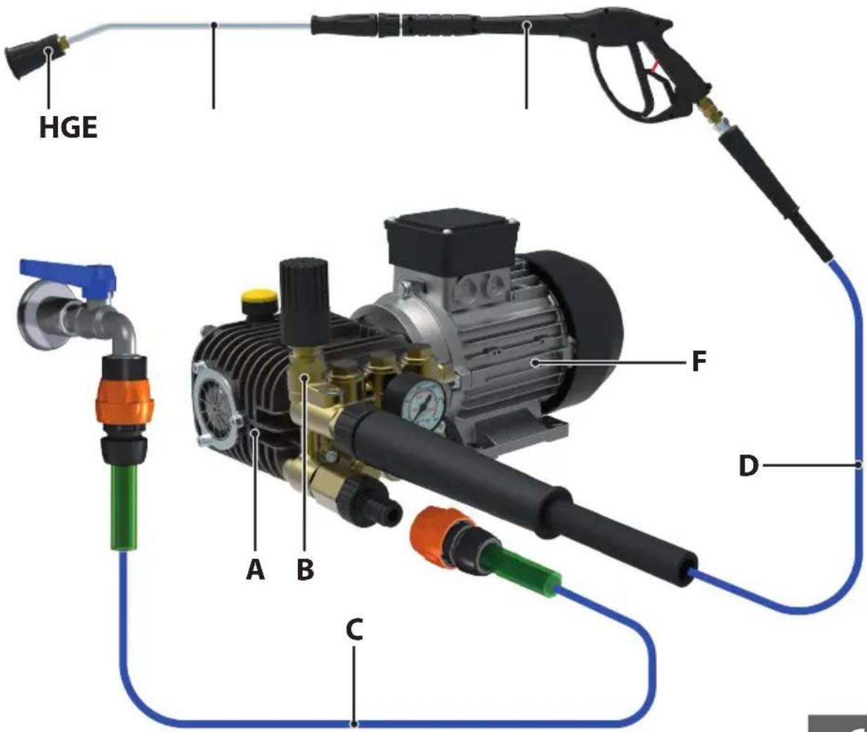
For the hydraulic suction, delivery and bypass connections, refer to the following table and to Fig. 4, which represents a generic diagram of a possible machine integrating the pump.
A Pump
B Pressure unloader /regulation valve
C Suction circuit
D Delivery circuit
E Spray gun (example of accessory)
F Motor
G Lance
H Nozzle head
EN
CAUTION
- Follow the connection instructions already indicated in the "CHECKING AND CONNECTING UP TO THE WATER SUPPLY" and "SPECIFICATIONS AND TECHNICAL DATA" paragraphs.
In particular, the suction circuit must be sized so as not to determine on the pump suction fitting: - a pressure higher than 8 bar/116 psi;
- At pump suction, a filter of adequate dimensions must be fitted. In case of doubts, contact the Manufacturer.
- The suction pipes must have a suitable internal diameter and a nominal pressure of 10 bar/145 psi.
- The delivery pipes must have a nominal pressure not below the pump max. pressure.
On the models AW, BW, EW, FW, FW2, HW, LW, RW, SW, TW and ZW, suction and delivery fittings are available both on the right side and on the left side of the head.
PRESSURE UNLOADER/REGULATION VALVE
In the models in which it is already built-in (pumps marked with the letter K preceded by a dash and pumps of the AX and BX series), this is factory set so maximum pump pressure is achieved, using a nozzle which also allows having a small flow rate in bypass (at least 0.3-0.6 l/min/0.08-0.16 USgpm).
The Manufacturer's Technical Assistance Service is at the disposal of the Skilled Technician to provide all the information needed, taking into account the fact that such adjustment may have to be corrected according to the plant engineering configuration in which the pump is installed.
RESETTING THE PRESSURE UNLOADER/REGULATION VALVE

WARNING
- Operating pressure must never exceed the maximum value indicated for the pump (see also the "SPECIFICATIONS AND TECHNICAL DATA" paragraph).
To reset the valve, proceed as follows (refer to Fig. 4):
- remove the plastic knob (15) by pulling it upwards;
- loosen the Allen screw (a);
- turn the retention ring nut (b) anticlockwise, so as to partially unscrew it;
- set the required pressure by means of the hexagonal knob (c) (turn clockwise to increase the pressure, anticlockwise to reduce the pressure);
- turn the retention ring nut (b) clockwise, to tighten it;
- fully tighten the Allen screw (a).
SPECIAL MAINTENANCE
Follow the instructions in the corresponding paragraph of section one.
The tightening torques to be used are shown on the following table.
| Tightening torques Nm (lb.ft) | ||||||||
| Description AX BX BW AW LW | ZW FW | Adhesive to be applied | ||||||
| a | Head screws 25 (18,4) 25 (18,4) 10 | (7,4) | < 230bar 10 (7,4) | 10 (7,4) 25 (18,4) | ||||
| > 230bar 80 (59,0) | ||||||||
| b | Valve caps (aluminium head) 35 (25,8) 40 (9,5) Loctite 243 | |||||||
| Valve caps (brass head) 45 (33,2) 45 (33,2) 45 (33,2) 45 (33,2) 45 (33,2) 45 (33,2) 45 (33,2) 45 (33,2) 45 (33,2) 45 (33,2) 45 (33,2) 45 (33,2 45 (33,2) 45 (33,2) 45 (33,2) 45 (33,2) 45 (33,2) 45 (33,2) 45 (33,2) 45 (33,2) 45 (33,2) 45 (33,2) 45 (33,2) | < 230bar 50 (36,9) | 50 (36,9) | Loctite 243 | |||||
| > 230bar 60 (44,3) | Loctite 243 | |||||||
| c | Cover screws | 4 (3,0) | 4 (3,0) | 4 (3,0) | 9 (6,6) | |||
| e | Crankcase cover screws | 9 (6,6) | 9 (6,6) | 9 (6,6) | 4 (3,0) | |||
| f | PTO flange screws | 9 (6,6) | 9 (6,6) | 9 (6,6) | 25 (18,4) | |||
| g | Plunger nuts | 6 (4,4) | 6 (4,4) | 6 (4,4) | 10 (7,4) | Loctite 243 | ||
| h | Eccentric shaft screw | 25 (18,4) | Loctite 243 | |||||
| i | Crankcase screws | 25 (18,4) 25 (18,4) | ||||||
| Tightening torques Nm (lb.ft) | |||||||
| Description | FW 2 | HW | RW | SW | TW | ||
| a | Head screws | 25 (18,4) 25 (18,4) | 25 (18,4) | 45 (33,2) 45 (33,2) | |||
| b | Valve caps (brass head) | < 230bar 50 (36,9) | 80 (59,0) | < 230bar 50 (36,9) | 80 (59,0) | Loctite 243 | |
| >230bar 80 (59,0) | >230bar 80 (59,0) | < 360bar 80 (59,0) | Loctite 243 | ||||
| >360bar 80 (59,0) | Loctite 270 | ||||||
| c | Cover screws | 9 (6,6) | 9 (6,6) | 9 (6,6) | 25 (18,4) | 25 (18,4) | |
| d | Connecting-rod screws | 25 (18,4) | Loctite 243 | ||||
| e | Crankcase cover screws | 4 (3,0) | 4 (3,0) | 4 (3,0) | 9 (6,6) | 9 (6,6) | |
| f | PTO flange screws | 25 (18,4) 25 (18,4) | 25 (18,4) | 25 (18,4) 25 (18,4) | |||
| g | Plunger nuts | 10 (7,4) | 10 (7,4) | 10 (7,4) | 15 (11,1) | 15 (11,1) | Loctite 243 |
| Tightening torques Nm (lb.ft) | |||||
| Description | DW | EW | Adhesive to be applied | ||
| a | Head screws | 25 (18,4) | 10 (7,4) | Loctite 243 | |
| b | Valve caps (suction) | 45 (33,2) | Loctite 243 | ||
| Valve caps (delivery) | 25 (18,4) | Loctite 243 | |||
| c | Cover screws | 4 (3,0) | |||
| e | Crankcase cover screws | 10 (7,4) | 10 (7,4) | ||
| f | PTO flange screws | 9 (6,6) | 9 (6,6) | ||
| g | Plunger nuts | 5 (3,7) | Loctite 243 | ||
AVANT-PROPOS
| Mobil Delvac MX 15W-40 | Total Rubia TIR 7400 15W-40 |
| Shell Rimula R4 15W-40 | ENI i-Sigma performance E7 15W-40 |
| Gazprom-Neft super oil GTD 15W-40 | Castrol GTX Professional 15W-40 |
FONCTIONNEMENT AVEC DÉTERGENT

ATTENTION
PROBLÈMES, CAUSES ET SOLUTIONS

ATTENTION
| Mobil Delvac MX 15W-40 | Total Rubia TIR 7400 15W-40 |
| Shell Rimula R4 15W-40 | ENI i-Sigma performance E7 15W-40 |
| Gazprom-Neft super oil GTD 15W-40 | Castrol GTX Professional 15W-40 |
| Mobil Delvac MX 15W-40 | Total Rubia TIR 7400 15W-40 |
| Shell Rimula R4 15W-40 | ENI i-Sigma performance E7 15W-40 |
| Gazprom-Neft super oil GTD 15W-40 | Castrol GTX Professional 15W-40 |
| Mobil Delvac MX 15W-40 | Total Rubia TIR 7400 15W-40 |
| Shell Rimula R4 15W-40 | ENI i-Sigma performance E7 15W-40 |
| Gazprom-Neft super oil GTD 15W-40 | Castrol GTX Professional 15W-40 |
text_image
QR code image containing encoded data, no visible human-readable text
COMET
INDUSTRIAL PUMPS DIVISION
COMET S.p.A. - Via G. Dorso, 4 - 42124 Reggio Emilia - ITALY
Tel. +39 0522 386111
E-Mail Italia: vendite@comet.re.it - fax +39 0522 386300
E-Mail Export: export@comet.re.it - fax +39 0522 386286
www.comet.re.it
1610 0325 00A - 06/2019 - Rev. 02