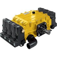
YB 150 - Pump Comet - Free user manual and instructions
Find the device manual for free YB 150 Comet in PDF.


| Product Type | Piston volumetric pump |
| Brand | Comet |
| Model | YB 150 |
| Category | Pump |
| Weight | 28 kg (62 lb) |
| Power source | Mechanical drive (power take-off or combustion engine) |
| Max pressure | 50 bar (725 psi) |
| Max flow rate | 131 L/min (34.6 US gpm) |
| Max rotation speed | 600 rpm |
| Min rotation speed | 400 rpm |
| Max water temperature | 60 °C (140 °F) |
| Min water temperature | 5 °C (41 °F) |
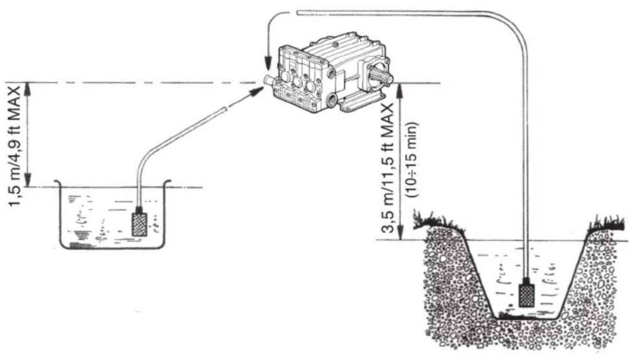
| Max suction lift | 1.5 m (4.9 ft); up to 3.5 m (11.5 ft) for 10-15 min |
| Max inlet pressure | 8 bar (116 psi) |
| Oil capacity | 1.5 L (0.4 US gal) - AGIP ROTRA MULTI THT |
| Sound level | 70 dB(A) |
| Routine maintenance | Check oil level and suction filter before each use; every 50h check circuit integrity and fastening |
| Oil change | Every 500 hours or at end of season |
| Safety devices | Pressure limiting/regulating valve; optional shaft guard; optional safety valve |
| Spare parts | Use only genuine Comet parts |
| Warranty | 24 months |
| Authorized uses | Agricultural treatments, gardening, pumping of detergents in aqueous solution, non-potable water |
Frequently Asked Questions - YB 150 Comet
User questions about YB 150 Comet
0 question about this device. Answer the ones you know or ask your own.
Ask a new question about this device
Download the instructions for your Pump in PDF format for free! Find your manual YB 150 - Comet and take your electronic device back in hand. On this page are published all the documents necessary for the use of your device. YB 150 by Comet.
USER MANUAL YB 150 Comet
(IT) POMPE A PISTONI
(EN) PISTON PUMPS
(FR) POMPES À PISTONS
natural_image
Two views of a mechanical component, one showing internal components and the other showing external housing (no visible text or symbols)YA - YB
ITALIANO
IT
ENGLISH
EN
FRANÇAIS
FR
ESPAÑOL
ES
DEUTSCH
DE
ΕΛΛΗΝΙΚΑ
EL
PORTUGUÊS
PT
РУССКИЙ
RU
EN- WARNING. Do not use the device without the previous reading of the instruction leaflet.
2
3
PREMESSA
This manual has two separate parts.
The first part is meant for both the end user and the SKILLED TECHNICIAN to read, whereas the second part is meant for the SKILLED TECHNICIAN alone.
By SKILLED TECHNICIAN we mean:
- The manufacturer of the machine (for instance a motorised pump) where the pump is fitted (in these instructions, the “machine with the pump” can also be a “system with the pump” such as a pumping station);
- A person who generally works at a Service Centre, who is trained and authorised to carry out extraordinary maintenance and repairs both on the pump and on the machine with the pump. Any work on electrical parts must be carried out by a SKILLED TECHNICIAN who is also a QUALIFIED ELECTRICIAN, that is to say a person who has the professional training and qualifications to check, install and repair electrical devices correctly and according to the current regulations in the country where the machine with the pump is installed.
PART ONE
GENERAL INFORMATION
Congratulations for choosing one of our products. We would like to remind you that operator safety, operating efficiency and protection of the environment were key factors for the design and manufacturing of this product.
In order to safeguard its features, it is important you read this manual with due care and attention and comply with the instructions provided.
Please pay particular attention when reading the parts of the text marked:

WARNING
because they contain important safety instructions for operating the pump.
THE MANUFACTURER IS NOT LIABLE FOR DAMAGE CAUSED BY:
- failure to comply with the information provided in this manual and in the manual for the machine with the pump;
- using the pump for other uses than those described in the section on "INTENDED USE";
- failure to comply with current regulations for safety and the prevention of accidents at work;
- incorrect installation;
- failure to carry out maintenance;
- unauthorised modifications or alterations;
- failure to use original spare parts or use of parts that are not specific for that particular pump;
• repairs not carried out by a SKILLED TECHNICIAN.
TERMS OF GUARANTEE
The guarantee is for 24 months starting on the date of the sales document (receipt of payment, invoice, etc.) provided the pump's guarantee certificate is filled-in properly and sent back to the Manufacturer within 10 days of the purchase date.
The purchaser has the right to have any parts replaced that are found faulty by the Manufacturer or his authorised representative in case of material or manufacturing faults, but has no right to demand a refund for any direct or indirect damage of any kind.
The purchaser must pay any expenses incurred for labour, packing and transport.
Products returned to the Manufacturer for repairs under the guarantee must have all their original parts
and must not have been tampered with or the request for repairs will be refused.
The parts replaced become the Manufacturer's property.
Payments may not be suspended or delayed as a result of faults or damage occurring during or after the guarantee period.
The guarantee does not cover the replacement of the pump and will automatically be terminated in case of failure to comply with the agreed terms of payment.
The guarantee does not cover:
- any form of direct or indirect damage caused by dropping the pump, incorrect use and failure to comply with the instructions designed to safeguard safety, installation, operation and maintenance that are provided in this manual;
- damage caused by pump inactivity during downtime for repairs;
- any parts subject to wear during normal operation;
- any parts found to be faulty as a result of negligence or incorrect use;
- damage caused by failure to use original spare parts or accessories or not those specifically authorised by the Manufacturer or caused by any repairs not carried out by aSKILLED TECHNICIAN.
The guarantee will be null and void and the Manufacturer will no longer be liable if the pump has been tampered with, especially its safety devices.
The Manufacturer has the right to implement any changes at any time in order to improve the product without incurring in any obligation to apply these changes to products that are already manufactured or have been delivered or are currently being delivered.
The information contained in this paragraph excludes any previous, specific or implicit condition.
ADDRESS OF THE MANUFACTURER
As far as concerns the address of the pump Manufacturer, what is specified in the “MANUFACTURER’S DECLARATION” attached to this manual is applicable.
USE AND STORAGE OF THE OPERATING AND MAINTENANCE MANUAL
The operating and maintenance manual is an important part of the pump and must be kept in a safe place so it can be referred to in the future.
The operating and maintenance manual provides important information for the safety of the operator and of anyone in the direct vicinity and for the protection of the environment.
Should the manual be misplaced or destroyed, ask an authorised dealer or an authorised service centre for another copy.
If the pump is sold, the operating and maintenance manual should be given to the new owner.
A great deal of effort went into the preparation of this manual. Should you find any mistakes, please notify the Manufacturer or an authorised service centre.
The manufacturer reserves the right to update or amend this manual at any time without notice.
Copying all or part of this manual is prohibited unless authorised by the Manufacturer in writing.
SYMBOLS
The symbol:

is used to highlight parts of the text where there is a strong risk of injury if you fail to follow the instructions and information provided.
The symbol:
CAUTION
is used to highlight parts of the text where there is a risk of pump damage if you fail to follow the instructions provided.
FEATURES AND SPECIFICATIONS
| YA 65 YA | 75 YB 75 YA | 130 YA 150 | YB 150 | |||
| MECHANICAL CONNECTIONPower consumption at max. rotation speed and pressure | 5,7 kW7,7 CV | 7,0 kW9,5 CV | 5,1 kW6,9 CV | 9,6 kW13,1 CV | 11,9 kW16,2 CV | 10,3 kW14,0 CV |
| Max. pump rotation speed | 650 RPM 600 RPM | 650 RPM 600 RPM | ||||
| Min. pump rotation speed | 400 RPM | |||||
| PUMP OILQuantity in weightQuantity in volume | AGIP ROTRA MULTI THT(1)1,3 kg - 2,9 lb1,5 l - 0,4 US gal | 1,2 kg - 2,6 lb1,4 l - 0,36 US gal | ||||
| HYDRAULIC CONNECTIONMax. supply water temperature | 60 °C - 140 °F | |||||
| Min. supply water temperature | 5 °C - 41 °F | |||||
| Min. suction difference in height | 1,5 m - 4,9 ft (per non più di 10÷15 min: 3,5 m - 11,5 ft) | |||||
| Max. supply water pressure | 8 bar - 116 psi | |||||
| PERFORMANCEFlow rate at maximum pressure | 55 l/min14,5 US gpm | 68 l/min18,0 US gpm | 66 l/min17,4 US gpm | 108 l/min28,5 US gpm | 128,5 l/min33,9 US gpm | 131 l/min34,6 US gpm |
| Maximum pressure | 5,0 MPa50 bar725 psi | 4,0 MPa40 bar580 psi | 5,0 MPa50 bar725 psi | 4,0 MPa40 bar580 psi | ||
| Sound pressure level | 70 dB(A) | |||||
| WEIGHT | 16 kg - 35 lb 28 kg - 62 lb | |||||
The features and specifications are provided for reference only. The Manufacturer reserves the right to alter products at any time.
(1) Corresponding oils:
| U.T.T.O.(Universal Tractor Trasmission Oil) | API GL-4 John Deere J20A |
| Massey-Ferguson M-1135 Ford M2C - 86 B Esso Torque Fluid 62 | |
| Mobil Mobilfluid 422 Ford M2C - 134 B/C Shell Donax TD | |
IDENTIFICATION OF PARTS
Please also refer to the Fig. 1 at the beginning of this use and maintenance manual.
- Pump foot
- Pump shaft
- Pump head
- Suction
- Delivery
-
Suction valve plug
-
Pump case
- Oil plug with vent and dipstick
- Delivery valve plug
- Identification plate
SAFETY DEVICES

WARNING
- The machine that includes the pump must be equipped with the safety devices shown below.
- If the machine in which the pump is integrated also features a safety valve, i.e., a max. pressure valve, suitably calibrated, which discharges excess pressure in case of a fault in the high-pressure circuit, in the event of the safety valve tripping frequently, immediately stop using the machine in which the pump is integrated and have it checked by a Skilled Technician.
- The possible output of the safety valve must not be spread in the environment.
- In case of breaking or damaging of the pump shaft protection, do not absolutely use the machine that includes the pump without having it checked by a Skilled Technician.
- During the use, do not place feet or hands on the pump shaft protection.
a) Safety valve.
Available as optional accessory.
It is a maximum pressure valve which has been duly calibrated and that discharges the over-pressure in excess in case of failure in the pressure adjusting system.
b) Pump shaft protection.
Available as optional accessory.
It is a device that prevents the operator to come into contact with the rotating parts of the pump shaft.
c) Pressure limiting/control valve
Available as optional accessory.
It is a duly adjusted valve that makes it possible for the pumped liquid to return to the pump suction, by inhibiting the onset of dangerous pressures when you close the water gun or when you try to set pressure values above the maximum allowed ones. A pressure limiting/adjusting valve equipped with stopping/distributing devices of the pumped fluid (for instance taps) is usually called pump control unit. For simplicity reasons, in this manual we will call control unit both the pressure limiting/adjusting valve and the pump control unit.
IDENTIFICATION PLATE
The identification plate (10) has the serial number and the main specifications for the pump: model, delivery, maximum pressure, maximum rotation speed.
The identification plate is located on the case upper part.

WARNING
- If the identification plate becomes worn due to use, ask an authorised dealer or service centre for a replacement.
INTENDED USE

WARNING
- The pump is only intended for the following uses:
- protection treatments of cultivation for agriculture and gardening;
- pumping of detergents in watery solution;
- pumping of water not used for food.
• The pump is not intended for use with: - water-based solutions whose density and viscosity is higher than water;
- chemical solutions when their compatibility with the pump materials is unknown;
- sea water or water with a high concentration of salt;
- any kind of fuel or lubricant;
- flammable fluids or liquefied gases;
- liquids for food use;
- any kind of solvent or thinner;
- any kind of paint;
- liquids whose temperature is above 60^ C/140 °F or below 5^ C/41 °F;
- liquids containing suspended granules or solid particles.
- The pump must be not be used to wash: people, animals, energized electrical devices, delicate items, the pump itself or the machine where it is fitted.
- The accessories (standard and optional) used together with the pump must be those approved by the Manufacturer.
- The pump is not suitable for use in special conditions, such as in environments with a corrosive or explosive atmosphere.
- Contact the Manufacturer's service centre for information on using the pump on board motor vehicles, boats or aircraft, as special conditions may apply.
ANY OTHER USE IS PROHIBITED.
THE MANUFACTURER IS NOT LIABLE FOR ANY DAMAGE CAUSED BY INCORRECT OR IMPROPER USE.
OPERATION

WARNING
- Do not operate the pump if the machine where it is fitted does not conform to the safety regulations set down in European Directives. This conformity is guaranteed by the € mark and the Declaration of Conformity issued by the Manufacturer of the machine where the pump is fitted.
- Read the information provided in this manual and in the instructions for the machine with the pump with due care before operating the pump. It is particularly important to make sure you have understood how the pump and the machine with the pump work as regards fluid sensing.
- Due care and attention is needed when using the pump. Never let other people use the pump unless you are sure they have read these instructions and know how to operate the pump. The pump must not be used by children or persons without adequate training.
- Comply with the safety information provided in the operating and maintenance manual of the machine with the pump especially as regards the use of personal protective equipment (safety goggles, ear muffs, face masks etc.).
- Comply with the safety information in the operating and maintenance manual of any optional accessories that are used.
-
Do not use the pump if:
-
the pump has fallen or has been knocked;
- you can see leaking oil;
- you can see leaking water.
and have the pump checked over by a SKILLED TECHNICIAN.
- Pay special attention when the pump is used in situations where moving vehicles could crush or damage the delivery hose and the spraying gun.
- The pump should always be monitored and remain out of children's reach while it is working. Pay special attention when pumps are used close to children's nurseries, hospitals and residential care homes because unassisted children, elderly or disabled people may in the vicinity.
- You must wear proper work gear before you start to use the pump for protection against potential impact with the pressurised water. Do not operate the pump near people who are not wearing protective work gear.
- Water can be dangerous at high-pressure if it is not used correctly. Do not point the spray towards people, animals, energized electrical devices or the pump itself.
- Grip the spraying gun firmly during use in order to counter the recoil effect you will feel when you press the control lever.
- Do not point the spray of water towards yourself or any other person with the intent of washing clothes or shoes.
- Do not point the spray of pressurised water towards any materials containing asbestos or other substances that are a health hazard.
- Make sure the pump's moving parts are protected and cannot be accessed by unauthorised personnel.
- Do not approach the pump's moving parts, even if they are protected.
- Do not remove the safety guards that protect moving parts.
- Do not carry out maintenance on the pump when it is running.
- Comply with the information in the section on "INTENDED USE".
- Do not alter how the pump has been installed, especially how it has been secured or its hydraulic connections.
- Do not operate any taps on the pump unless they are connected to an application that prevents the accidental release of pumped liquid.
- Do not tamper with controls and safety devices.
- The machine with the pump must be connected to the mains electricity supply by a Qualified Electrician according to the current standards in the country where it is used.
- The machine with the pump must not be operated in enclosed environments if it is run by a combustion engine.
PRELIMINARY CHECKS

WARNING
- Carry out the preliminary checks recommended by the Manufacturer of the machine with the pump.
- Check all the delivery hoses are closed or are connected to a closed application (such as a closed tap or a spray gun in the closed position).
- A SKILLED TECHNICIAN should complete the extraordinary maintenance as required.
CAUTION
- In applications where the pump is driven by a cardan shaft, avoid thrust against the pump shaft caused by incorrect cardan operation (poor greasing of sliding parts, incompatible rotating angles with the type of cardan).
- Make sure ice does not form inside the pump when working at very low temperatures.
- Complete all routine maintenance, especially with regard to the oil.
a) Replace the oil plug without vent with the oil plug with vent and dipstick (8). This operation could have been already carried out by the Producer of the machine that includes the pump.
b) Check that with stopped pump the oil level is included between the two marks on the dipstick of the plug (8). Remember that the oil level must be always checked with pump at a standstill and completely cooled down. For a possible topping up, refer to the types of lubricants that are reported on paragraph “FEATURES AND TECHNICAL DATA”.
HYDRAULIC CONNECTION

WARNING
- Do not connect to the mains water supply.
- All hoses must be secured to their couplings with clamps.
Refer to Fig. 2 for a general layout of a typical machine with the pump and to the following table for the hydraulic connections for the suction, delivery and by-pass lines:
| 1. Tank2. Suction filter3. Suction circuit4. Pump | 5. Delivery circuit6. By-pass circuit7. Spray gun (suggested application) |
a) For use with a spray gun:
- Completely unwind the high-pressure hose;
- by means of the suitable clamp, connect the high-pressure hose to a tap of the pump or to the control unit;
- Connect the gun to the high-pressure hose and make sure the lever is shut.
b) Connect the suction hose to its coupling if this has not already been done by the Manufacturer of the machine with the pump, and check the filter is clean.
CAUTION
- The pressure of the supplied water must not be higher than 8 bar/116 psi;
- Do not operate the pump with suction differences in height that are higher than 1.5 m/4.9 ft. The pump can suck occasionally, for periods of 10÷15 minutes, from differences in height up to 3.5 m/11.5 ft: it must not suck from higher positions;
- The pump intake must be fitted with a suitably sized filter. Contact aSKILLED TECHNICIAN in case of doubt. Check the filter is always clean;
- The suction hose must have an inner diameter that is equal to the outer one of the suction connector (available as optional accessory having a diameter of 30 mm for YA 65, YA 75 and YB 75 and a diameter of 40 mm for YA 130, YA 150, and YB 150) and must have a rated pressure that is equal to 10 bar/145 psi.
- The internal diameter of the delivery hoses must be equal to the external diameter of the delivery couplings and the rated pressure must not be less than the pump's maximum rated pressure;
- Do not supply the pump with water above 60^ / 140^ or below 5^ / 41^ ;
- Do not run the pump dry for long periods;
- Do not supply the pump with sea water or dirty water. Should this happen, run the pump for several minutes with clean water.
STARTING WORK

WARNING
- Follow the start-up procedure recommended by the Manufacturer of the machine with the pump.
- Read the information and warnings on the label of any chemicals to be distributed with the pump with due care to prevent potential danger to people and the environment.
- Keep chemicals in a safe place and out of children's reach.
- In case of contact with the eyes, wash immediately with water and contact a doctor immediately: remember to take the container of chemical with you.
- In case of swallowing, do not provoke vomiting and contact a doctor immediately: remember to take the container of chemical with you.
- Never operate the pump at pressures above the maximum operating pressure (refer to section of FEATURES AND SPECIFICATIONS")
For what follows, refer also to the documentation accompanying the control unit:
a) Set the delivery pressure to zero by operating on the control unit, so that you can set it to "by-pass".
b) Start the pump to prime it.
c) Operate on the control unit, so that you can set it to “pressure”.
d) Rotate the pressure adjusting knob of the control unit in the suitable way, until you reach the wished pressure value.
CAUTION
- For rapid pump priming, carry out step a) each time the pump is drained.
- During the first hours of pump operation, check the oil and top up, if necessary, as instructed in the section on “PRELIMINARY CHECKS”.
STOPPING WORK

WARNING
- Follow the instructions for stopping work provided by the Manufacturer of the machine with the pump. THERE MUST BE NO MOVING PUMP PARTS AND NO PRESSURISED LIQUID IN THE HOSES.
a) Turn off the delivery pressure as described in point a) in the section on "STARTING WORK".
b) Stop the pump.
STORAGE

WARNING
- Follow the storage instructions provided by the Manufacturer of the machine with the pump.
CAUTION
- Read the instructions for storage in the operating and maintenance manual for the machine with the pump. After using it for the last time, clean out the pump by taking up clean water. Never store the pump with pumped fluid inside it.
- THE PUMP IS SENSITIVE TO FROST. In cold environments, protect the pump by preventing the formation of ice inside the pump by taking up antifreeze (diluted appropriately for the envisaged temperature). Drain it completely by running it dry for several minutes.

WARNING
- Dispose of antifreeze properly.
CLEANING AND MAINTENANCE

WARNING
- Cleaning and maintenance can only be carried out after you have completed the steps described in the section on “STOPPING WORK” so THERE ARE NO PARTS OF THE PUMP IN MOTION AND THERE IS NO PRESSURISED LIQUID IN THE HOSES.
ALWAYS REMEMBER TO DISCONNECT THE POWER SUPPLY.
TO DISCONNECT THE PLUG CONTACT (PETROL ENGINES), THAT IS TO SAY TO REMOVE THE IGNITION LOCK KEY (DIESEL ENGINES)
EN
ROUTINE MAINTENANCE
Follow the instructions in the section on “STOPPING WORK” and in the table below.0
| MAINTENANCE SCHEDULE ACTION | |
| Every time the pump is used. • Check the | amount and condition of the oil.• Check the suction filter and clean, if necessary. |
| Every 50 hours. • Check the suction circuit. | • Check the pump is secured to the machine (1).IF THE PUMP IS NOT SECURE, DO NOT USE THE MACHINE AND CONTACT A SKILLED TECHNICIAN. |
(1) Check more frequently if the pump is subject to significant vibration (tracked tractors, combustion engines, etc)
CAUTION
- During operation, the pump should not be excessively noisy and there must be no visible leaks of water or oil underneath it.
Should this occur, have the machine checked by a SKILLED TECHNICIAN.
- Extraordinary maintenance may only be carried out by a QUALIFIED TECHNICIAN.
- Dispose of old oil properly.
Refer to the table of extraordinary maintenance below.
| MAINTENANCE SCHEDULE ACTION | |
| Every 500 hours or at the end of every season. • | Check the delivery/suction valves (1).Check and possibly replace the gaskets (2).Change the oil (3).Check the pump screws are tight (4). |
(1) Check more frequently when using liquids containing suspended abrasive particles.
(2) If you use particularly aggressive chemical products, we recommend to replace the gaskets independently of their state.
(3) The first oil change is to be carried out after 50 hours.
(4) Check more frequently if the pump is subject to significant vibration
CAUTION
- The information provided in the table is only a guide. Maintenance may be needed more frequently in particularly harsh operating conditions.
DISMANTLING AND DISPOSAL
The pump may only be dismantled by qualified personnel who must comply with the current regulations in the country where the pump is installed.
TROUBLESHOOTING

WARNING
- Always follow the instructions for “STOPPING WORK” before attempting any of the solutions below. Contact a SKILLED TECHNICIAN if you are unable to resume correct pump operation using the information in the following table.
| PROBLEM CAUSE SOLUTION | ||
| The pump does not prime Air intake | Control valve set for pressure. | Check the suction circuit is intact. Reset pressure by setting the pump to by-pass. |
| The pump does not reach maximum pressure | Low pump rotation speed. Incompatible application (such as a nozzle that is worn or is too big) | Restore the correct rotation speed. Replace the application. |
| Pressure and delivery not regular (pushbuttons). | Air intake Check the suction circuit is intact. | |
| Excessive noise. Blocked suction circuit. Excessive temperature of the supply water. | Check the suction circuit. Supply the pump with water below 60 °C/140 °F. | |
PART TWO
(FOR THE SKILLED TECHNICIAN ONLY)

WARNING
- This part of the manual is intended for the SKILLED TECHNICIAN only and not for the pump operator.
UNPACKING

WARNING
- Wear gloves and safety goggles when unpacking to protect your hands and eyes.
- Packaging materials (plastic bags, clamps etc.) can be dangerous: never leave them within the reach of children.
- Dispose of packaging materials properly according to the current regulations where the pump is installed. Plastic bags and other plastic materials are not eco-friendly.
• After unpacking the pump, check it is not damaged and make sure its identification plate is attached to the case.
In case of doubt, do not use the pump and contact your dealer.
STANDARD EQUIPMENT
Make sure that pump supplied also has the following:
• oil plug with vent and dipstick (8);
- operating and maintenance manual;
- guarantee certificate.
Contact your dealer in case of doubt.

WARNING
• These instructions and the guarantee certificate must always accompany the pump and be handed over to the end user of the pump.
INSTALLATION

WARNING
- It is the responsibility of the SKILLED TECHNICIAN to follow the instructions provided in this manual. The specifications of the motor (electric motor or combustion engine) to be connected to the pump must be suitable for the performance and the specifications of the pump (power, speed of rotation, flanges, etc.) listed in the technical documents provided by the Manufacturer.
- The design of the machine with the pump must safeguard compliance with the safety standards required by European Directives. This conformity is guaranteed by the mark and by the Declaration of Conformity issued by the Manufacturer of the machine with the pump.
- The pump must be installed and operated horizontally.
- The pump must be fixed in a stable way by means of the feet that are supplied by the Producer.
- As this is a positive-displacement pump, it must always be fitted with a pressure control/limit valve.
OPTIONAL ACCESSORIES

WARNING
- Use of unsuitable optional accessories may endanger proper pump operation and may make it dangerous. Only use the original accessories authorised by the Manufacturer.
- Read the documentation provided with the optional accessories for general information, safety notices and instructions for installation and maintenance.
There are many optional accessories you can use in addition to the standard equipment supplied with the pump:
- safety valve;
- pump shaft protection;
• control unit;
• suction filter (bottom basket); - suction connector of various shapes and dimensions;
- pressure gauge;
• high-pressure delivery hoses; - hose reel;
• spraying lances of various types.
Contact your dealer for further details.
APPLICATIONS
CAUTION
- Pump applications must comply with the principals of good mechanics. The Manufacturer's Service Department can provide any additional information for installers.

WARNING
- Protect the moving parts with suitable protections. Special care must be paid to the pulley applications and to the power-take-off of the tractor.
- The pump must not work at a rotation speed that is higher than the one that can be read on the plate (10) (see also what reported in paragraph "FEATURES AND TECHNICAL DATA").
- In case of through shaft, do not overcome the maximum available power values that shown in the table below.
| Type of through shaft Available power on the through shaft | ||
| [CV] [kW] | ||
| Cardan joint 1” 3/8 M | 22 | 16 |
| 6 holes with three screws M8 | 6 | 4,4 |
| 6 holes with three screws M10 | 9 | 6,6 |
CAUTION
- The pump must be installed in a position that is perfectly levelled to the mechanical driving organs (amplifiers, reduction units, etc.).
- The pump can rotate both in clockwise and counter-clockwise direction.
| Through shaft cardan joint 1”3/8 M - cardan joint 1”3/8 M | Non-through shaft cylinder shape ∅35 mm | Through shaft cardan joint 1”3/8 M - 6 holes | Pulley Reduction unit | |
| YA 65 | STD VD (1) (3) | |||
| YA 75 | STD VD (1) (3) | |||
| YA 130 | STD VD (2) | |||
| YA 150 | STD VD (2) | |||
| YB 75 | STD VD (1) (3) | |||
| YB 150 | STD VD (2) |
STD = Standard
VD = Available Version
(1) Available pulley: 2 races A ∅p 247; 2 races A ∅p 292; 3 races A ∅p 292; 3 races A ∅p 350.
(2) Available pulley: 5 races A ∅p 320.
(3) Available reduction unit: 1:6,44; 1:5,09.
HYDRAULIC CONNECTION
Follow the instructions provided in the relevant section in part one.
In particular, the suction circuit must be dimensioned so that the pressure on the pump suction coupling:
• does not exceed 8 bar/116 psi
- the vacuum does not exceed 0.3 bar / 4.35 psi; vacuum values for the suction up to max. 0.5 bar/7.25 psi are only allowed for operating periods of 10 ÷ 15 minutes (normally enough to carry out, for instance, the filling operation of the tank of the machine that includes the pump).
For the suction, the pump must be equipped with a filter having the suitable dimensions.
It is possible to connect suction and delivery connectors both on the left and right side of the head (3).
Observe the instructions reported in paragraph of the first part.
The torque wrench settings to be used are shown in the following table.
| Torque wrench setting Nm (lb.ft) | ||||
| Description | YA 65 - YA 75YB 75 | YA 130 - YA 150YB 150 | Fluid to be appliedto the thread | |
| Head screws | 45 (33,2) Grease | |||
| Valve plug screws | 45 (33,2) | |||
| Bearing flange screws | 45 (33,2) | |||
| Connecting rod screws | 25 (18,4) Loctite 243 | |||
| Case cover screws | 20 (14,8) | |||
| Feet screws | 45 (33,2) | |||
| Pistons screws | 35 (25,8) Loctite 243 | |||
| Grains for piston screws | 40 (29,5) Loctite 270 | |||
| Screw for conical shaft | 75 (55,3) -- | -- | Loctite | 243 |
AVANT-PROPOS
CONDITIONS DE GARANTIE
PROBLÈMES, CAUSES ET SOLUTIONS

ATTENTION
PROBLEMAS, CAUSAS E SOLUÇÕES

ATENÇÃO

COMET
AGRICULTURAL DIVISION
COMET S.p.A. - Via G.Dorso, 4 - 42124 Reggio Emilia - ITALY
Tel. +39 0522 386111
E-mail Italia: vendite@comet.re.it - fax +39 0522 386300
E-mail Export: export@comet.re.it - fax +39 0522 386286
www.comet.re.it
1610 0709 00C - 11/2015 - REV 03
- (IT) POMPE A PISTONI
- PREMESSA
- PART ONE
- GENERAL INFORMATION
- WARNING
- TERMS OF GUARANTEE
- ADDRESS OF THE MANUFACTURER
- USE AND STORAGE OF THE OPERATING AND MAINTENANCE MANUAL
- SYMBOLS
- CAUTION
- IDENTIFICATION OF PARTS
- SAFETY DEVICES
- a) Safety valve.
- b) Pump shaft protection.
- c) Pressure limiting/control valve
- IDENTIFICATION PLATE
- INTENDED USE
- OPERATION
- PRELIMINARY CHECKS
- HYDRAULIC CONNECTION
- STARTING WORK
- STOPPING WORK
- STORAGE
- CLEANING AND MAINTENANCE
- ROUTINE MAINTENANCE
- DISMANTLING AND DISPOSAL
- TROUBLESHOOTING
- PART TWO
- (FOR THE SKILLED TECHNICIAN ONLY)
- UNPACKING
- STANDARD EQUIPMENT
- INSTALLATION
- OPTIONAL ACCESSORIES
- APPLICATIONS
- AVANT-PROPOS
- CONDITIONS DE GARANTIE
- PROBLÈMES, CAUSES ET SOLUTIONS
- ATTENTION
- PROBLEMAS, CAUSAS E SOLUÇÕES
- ATENÇÃO
Brand : Comet
Model : YB 150
Category : Pump