
LIFE SM70 - Sewing machine MEDION - Free user manual and instructions
Find the device manual for free LIFE SM70 MEDION in PDF.

| Product type | Sewing machine |
| Brand | Medion |
| Model | LIFE SM70 |
| Dimensions (L x D x H) | 345 x 145 x 270 mm |
| Weight | Approximately 5 kg |
| Power supply | 220-240 V ~ 50 Hz |
| Rated power | 71 W (motor 70 W, lamp 1 W LED) |
| Pedal | Type HKT72C, 200-240 V ~ 50 Hz, 0.5 A, protection class II |
| Available stitch types | Straight stitch, zigzag stitch, satin stitch, invisible stitch, elastic stitch, overlock stitch, buttonhole |
| Stitch length adjustment | 0 to 3.6 mm |
| Special features | Reverse sewing, free arm, removable extension table, use of twin needle |
| Accessories included | 3 bobbins, lint brush with seam ripper, buttonhole foot, needles (3x 90/14 + 1 twin needle), felt pads, multi-function screwdriver, optional spool holder, protective cover |
| Maintenance | Regular cleaning of feed dogs and bobbin case; lubrication with special sewing machine oil |
| Safety | Turn off and unplug before maintenance; do not use outdoors; keep out of reach of children under 8 years old |
| Spare parts and repairability | Needles available in stores; repair only by authorized service center |
| Intended use | Private use, assembly of light to heavy fabrics, light leather, decorative stitches |
Frequently Asked Questions - LIFE SM70 MEDION
User questions about LIFE SM70 MEDION
0 question about this device. Answer the ones you know or ask your own.
Ask a new question about this device
Download the instructions for your Sewing machine in PDF format for free! Find your manual LIFE SM70 - MEDION and take your electronic device back in hand. On this page are published all the documents necessary for the use of your device. LIFE SM70 by MEDION.
USER MANUAL LIFE SM70 MEDION
natural_image
White sewing machine with '4 Step Buttonhole' label and brand 'medion' on base (no additional text or symbols visible)Nähmaschine Machine à coudre Naaimachine Màquina de coser Macchina da cucire Sewing machine
MEDION LIFE SM70 (MD 11179)
Inhaltsverzeichnis
natural_image
Diagram showing connection between a device with an attached power strip and a switch, no text or symbols present
natural_image
Line drawing of a foot pressing down on a wooden block with an arrow indicating motion (no text or symbols)
natural_image
Line drawing of a sewing machine with a side panel and internal components (no text or symbols)natural_image
Technical line drawing of a mechanical device with no visible text or symbolsnatural_image
Technical line drawing of a mechanical device interior with no visible text or symbols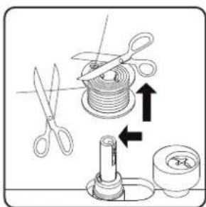
natural_image
Technical line drawing of a sewing machine with a gear and mechanical components, showing no text or symbols.
natural_image
Technical line drawing of a sewing machine with a circular component inserted, showing mechanical components and a directional arrow (no text or symbols)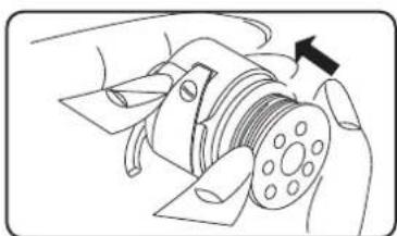
natural_image
Diagram of a hand operating a mechanical component with a black arrow indicating direction (no text or symbols present)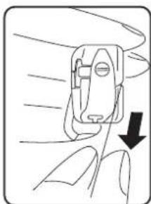
natural_image
Line drawing of a hand holding a small mechanical device with a downward arrow indicating motion (no text or symbols)
natural_image
Illustration of a finger pressing a button with an arrow indicating direction (no text or symbols)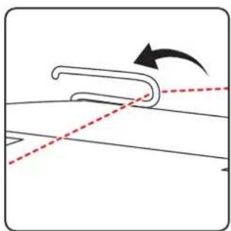
natural_image
Diagram showing a curved mechanical component with an arrow indicating rotation, no text or symbols presentnatural_image
Diagram of a mechanical device with curved and dashed lines indicating motion, showing internal components and rotation arrow (no text or symbols)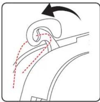
natural_image
Diagram of a curved mechanical component with motion arrows indicating movement (no text or symbols)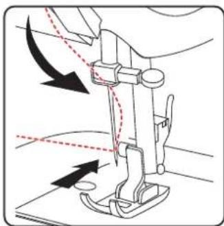
natural_image
Diagram of a sewing machine needle with arrows indicating force direction (no text or symbols)natural_image
Line drawing of a sewing machine handle with two vertical pins and a circular button (no text or symbols)natural_image
Diagram showing a curved pipe or tube with dashed lines indicating direction, no text or symbols present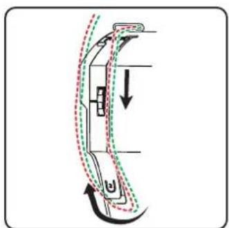
natural_image
Diagram of a car interior showing airflow path with arrows indicating direction (no text or symbols)natural_image
Diagram of a curved mechanical component with motion arrows indicating rotation (no text or symbols)
natural_image
Line drawing of a sewing machine needle with arrows indicating force direction (no text or symbols)natural_image
Technical diagram of a sewing machine needle with directional arrows indicating movement (no text or labels)natural_image
Diagram of a sewing machine needle and base plate assembly (no text or symbols)9. Einstellungen
natural_image
Pure mechanical component diagram without any text, numbers, or symbols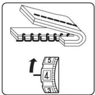

natural_image
Technical illustration of a sewing machine needle stitching on a base, with an inset showing the same component (no text or symbols present)natural_image
Diagram of a sewing machine needle stitching on a base, with an inset showing the same mechanism (no text or symbols present)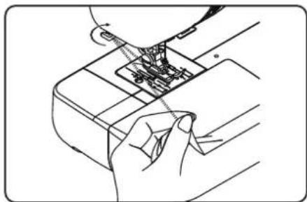
natural_image
Line drawing of a hand inserting a component into a device (no text or symbols)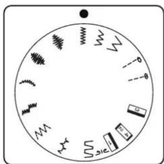
natural_image
Circular diagram with abstract symbols and arrows, no readable text or labelsnatural_image
Five abstract wavy line patterns arranged horizontally (no text or symbols)natural_image
Diagram showing two steps of a cable or cable installation on a panel, with no visible text or symbols.
natural_image
Line drawing of a sewing machine needle stitching fabric (no text or symbols)natural_image
Technical line drawing of a mechanical assembly with levers and gears (no text or symbols)10.11. Knopfl öcher

TIPP
natural_image
Technical diagram of a mechanical assembly with two views showing internal components and directional arrows (no text or labels)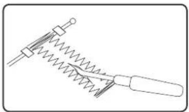
natural_image
Simple line drawing of a mechanical tool with spring and handle (no text or symbols)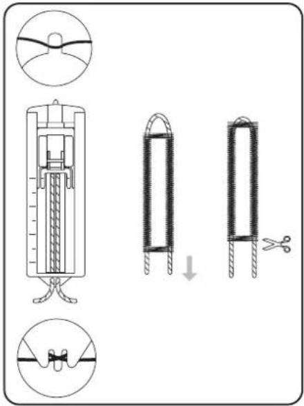

natural_image
Simple line drawing of a hand holding a string above a grid with dashed lines (no text or symbols)10.12. Kräuseln
Nähfuß: Standardfuß
Stichlänge: 4
natural_image
Diagram showing a screwdriver with directional arrows indicating motion (no text or symbols)
natural_image
Technical diagram of a sewing machine needle with directional arrows indicating movement (no text or labels)
natural_image
Technical line drawing of a sewing machine needle and screw base (no text or symbols)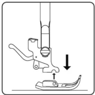
natural_image
Diagram of a sewing machine needle and foot with a downward arrow indicating measurement or positioning (no text or symbols)11.2.2. Einsetzen
natural_image
Technical line drawing of a sewing machine with three screws and a base plate (no text or symbols)
natural_image
Line drawing of a sewing machine needle being inserted into a socket (no text or symbols)natural_image
Technical line drawing of a mechanical assembly with a rotating component and a magnified view (no text or symbols)
natural_image
Technical line drawing of a mechanical assembly with directional arrows indicating motion (no text or symbols)
natural_image
Technical line drawing of a mechanical device with two circular components and a central hub (no text or symbols)natural_image
Mechanical assembly diagram showing a motor or gear mechanism with no visible text or symbolsnatural_image
Technical line drawing of a mechanical device with no visible text or symbolsnatural_image
Technical line drawing of a mechanical device with a central dial and mounting bracket (no text or symbols)natural_image
Mechanical assembly diagram showing a motor with rotating components and a highlighted section (no text or symbols)natural_image
Technical line drawing of a mechanical device with two circular components and a central hub (no text or symbols)natural_image
Technical line drawing of a sewing machine component with screws and fastener (no text or symbols)natural_image
Technical line drawing of a sewing machine with a side view showing internal components (no text or symbols)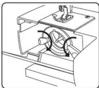
natural_image
Technical line drawing of a mechanical assembly with no visible text or symbols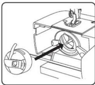
natural_image
Technical line drawing of a mechanical assembly with a rotating component and a magnified view (no text or symbols)natural_image
Diagram showing connection between a device with an attached switch and cable, no text or symbols present
natural_image
Line drawing of a foot pressing down on a wooden block with an arrow indicating motion (no text or symbols)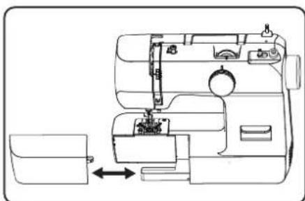
natural_image
Line drawing of a sewing machine with a side panel and internal components (no text or symbols)natural_image
Technical line drawing of a mechanical device with no visible text or symbolsnatural_image
Technical line drawing of a mechanical device interior with no visible text or symbolsnatural_image
Diagram showing a hand pouring liquid into a coiled spring and then into a cylindrical component with arrows indicating direction (no text or symbols)
natural_image
Technical line drawing of a sewing machine with a black arrow indicating a component (no text or symbols present)
natural_image
Mechanical assembly diagram showing a sewing machine with a circular component inserted, no text or symbols present
natural_image
Diagram of a hand operating a mechanical component with a black arrow indicating direction (no text or symbols present)
natural_image
Line drawing of a hand holding a small mechanical device with a downward arrow indicating motion (no text or symbols)
natural_image
Illustration of a finger pressing down on a small object with an arrow indicating direction (no text or symbols)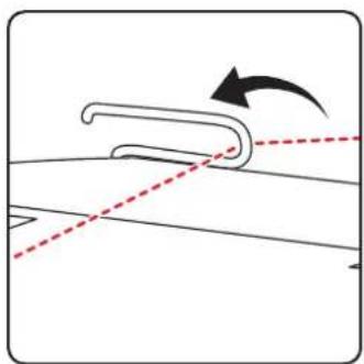
natural_image
Diagram showing a curved mechanical component with an arrow indicating rotation, no text or symbols presentnatural_image
Diagram of a device's internal structure with arrows indicating motion (no text or symbols)
natural_image
Diagram of airflow around a curved duct with directional arrows indicating flow direction (no text or symbols)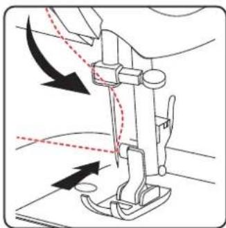
natural_image
Diagram of a sewing machine needle with arrows indicating force direction (no text or symbols)natural_image
Line drawing of a sewing machine handle with two vertical pins and a circular base (no text or symbols)natural_image
Diagram showing a curved mechanical component with dashed lines indicating alignment or movement, no text or symbols present.natural_image
Diagram of a curved mechanical component with dashed and dotted lines indicating motion or assembly (no text or symbols)i
natural_image
Diagram of a curved mechanical component with motion arrows indicating rotation (no text or symbols)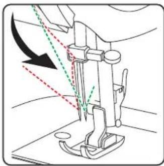
natural_image
Line drawing of a sewing machine needle with arrows indicating measurement or direction (no text or symbols)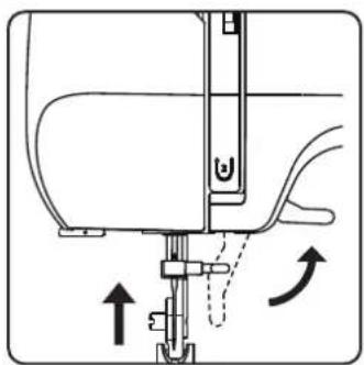
natural_image
Diagram of a sewing machine needle with directional arrows indicating movement (no text or symbols)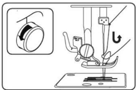
natural_image
Diagram of a sewing machine needle and fabric tray with no visible text or symbolsnatural_image
Simple line drawing of a mechanical device with no text or symbols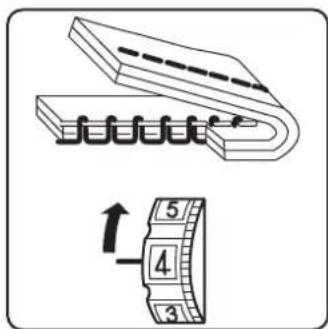

natural_image
Technical illustration of a sewing machine needle stitching on a base, with an inset showing the same component (no text or symbols present)natural_image
Diagram of a sewing machine needle stitching on a base, with an inset showing the same mechanism (no text or symbols present)10.7. Coupe du fi I
natural_image
Line drawing of a hand inserting a component into a device (no text or symbols)natural_image
Circular diagram with abstract symbols and arrows, no readable text or labelsPied-de-biche :....Pied standard
Pied-de-biche :....Pied standard
natural_image
Four abstract wavy line patterns arranged horizontally (no text or symbols)Pied-de-biche :....Pied standard
natural_image
Diagram showing two steps of a cable or cable installation with labeled points A, no text or symbols present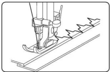
natural_image
Line drawing of a sewing machine needle stitching fabric (no text or symbols)Pied-de-biche :....Pied standard
natural_image
Line drawing of a sewing machine needle and chain (no text or symbols)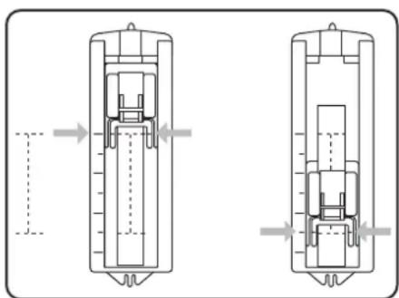
natural_image
Technical line drawing of a mechanical component with two views (top and side), showing internal components and alignment arrows (no text or symbols)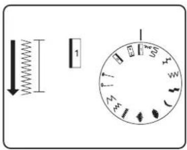
natural_image
Technical line drawing of a mechanical tool with spring and handle (no text or symbols)10.12. Fronçage
Pied-de-biche :....Pied standard
natural_image
Simple line drawing of a grid with diagonal lines and an arrow pointing upward (no text or symbols)Pied-de-biche :.... Pied standard
natural_image
Diagram showing a screwdriver with directional arrows indicating motion (no text or symbols)
natural_image
Technical diagram of a sewing machine needle with directional arrows indicating movement (no text or labels)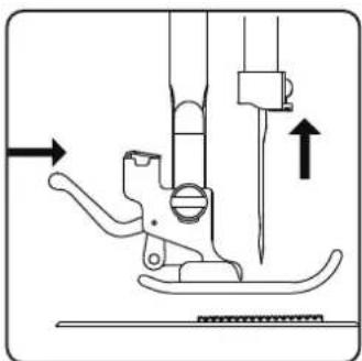
natural_image
Technical line drawing of a sewing machine needle and foot (no text or symbols)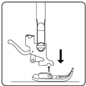
natural_image
Diagram of a sewing machine needle and foot with a downward arrow indicating measurement or positioning (no text or symbols)11.2.2. Mise en place du pied-de-biche
natural_image
Technical line drawing of a sewing machine needle with two screws and a base plate (no text or symbols)natural_image
Line drawing of a sewing machine needle being inserted into a socket (no text or symbols)natural_image
Technical line drawing of a mechanical assembly with a rotating component and a magnified view (no text or symbols)natural_image
Technical line drawing of a mechanical device with internal components and directional arrows (no text or symbols)
natural_image
Technical line drawing of a mechanical device with two circular components and a central hub (no text or symbols)natural_image
Technical line drawing of a mechanical assembly with no visible text or symbolsnatural_image
Technical line drawing of a mechanical assembly with no visible text or symbolsnatural_image
Technical line drawing of a mechanical device with a central rotating component and mounting base (no text or symbols)natural_image
Mechanical assembly diagram showing a motor with rotating components and a highlighted section (no text or symbols)natural_image
Technical line drawing of a mechanical device with two circular components and a central hub (no text or symbols)natural_image
Technical line drawing of a sewing machine component with screws and fastener (no text or symbols)▶ Retirez le capot avant (20).
natural_image
Technical line drawing of a sewing machine with a side view showing internal components (no text or symbols)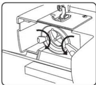
natural_image
Technical line drawing of a mechanical assembly with no visible text or symbols
natural_image
Technical line drawing of a mechanical device with a rotating component and a handle (no text or symbols)natural_image
Diagram showing connection between a device with an attached switch and power strip, no text or symbols present
natural_image
Line drawing of a foot pressing down on a rectangular object with a curved arrow indicating motion (no text or symbols)natural_image
Line drawing of a sewing machine with a side panel and internal components (no text or symbols)natural_image
Technical line drawing of a mechanical device with no visible text or symbolsnatural_image
Technical line drawing of a mechanical device interior with no visible text or symbols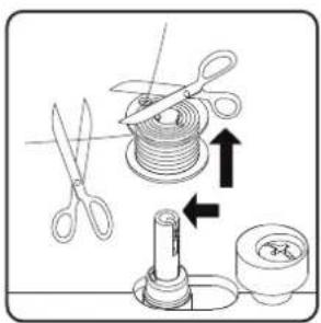

natural_image
Diagram of a sewing machine needle insertion into a base, showing mechanical components and a sewing machine (no text or labels)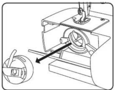
natural_image
Mechanical assembly diagram showing a motor with rotating components and a separate gear mechanism (no text or labels)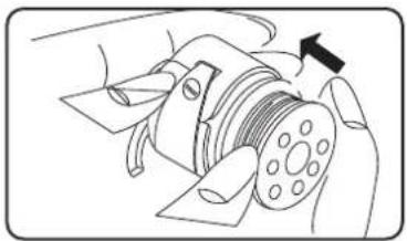
natural_image
Diagram of a mechanical device with a rotating shaft and housing, showing no text or symbols.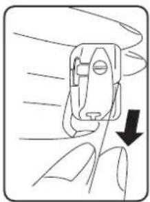
natural_image
Diagram of a hand holding a device with a downward arrow indicating force or movement (no text or symbols present)
natural_image
Illustration of a finger pressing down on a small object with an arrow indicating direction (no text or symbols)
natural_image
Diagram showing a curved mechanical component with an arrow indicating rotation, no text or symbols presentnatural_image
Diagram of a device with curved arm and directional arrows indicating motion (no text or symbols)
natural_image
Diagram of a curved mechanical component with motion arrows indicating movement (no text or symbols)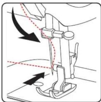
natural_image
Diagram of a sewing machine needle with arrows indicating force direction (no text or symbols)natural_image
Line drawing of a mechanical device with two cylindrical components and a base (no text or symbols)natural_image
Diagram showing a curved mechanical component with dashed lines indicating alignment or motion, no text or symbols present.natural_image
Diagram of a car interior showing curved movement with arrows indicating direction (no text or symbols)i
natural_image
Diagram of a curved mechanical component with motion arrows indicating rotation (no text or symbols)
natural_image
Line drawing of a sewing machine needle with arrows indicating force direction (no text or symbols)natural_image
Technical diagram of a sewing machine needle with directional arrows indicating movement (no text or labels)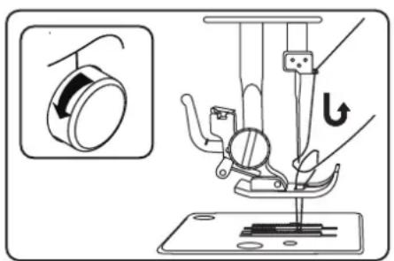
natural_image
Diagram of a sewing machine needle and fabric assembly (no text or labels)natural_image
Simple line drawing of a mechanical device with no text or symbols9.4. Draadspanningen controleren
9.4.1. Juiste naad
9.4.2. Onzuivere naden

natural_image
Technical illustration of a sewing machine needle stitching on a base, with an inset showing the same component (no text or symbols present)natural_image
Technical illustration of a sewing machine needle stitching on a base, with an inset showing the same mechanism (no text or symbols present)natural_image
Line drawing of a hand inserting a component into a device (no text or symbols)natural_image
Diagram showing two views of a roof or panel installation with labeled points A (no text or symbols beyond labels)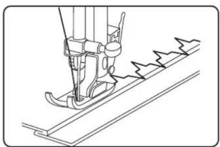
natural_image
Line drawing of a sewing machine needle stitching fabric (no text or symbols)natural_image
Technical line drawing of a sewing machine needle and chain (no text or symbols)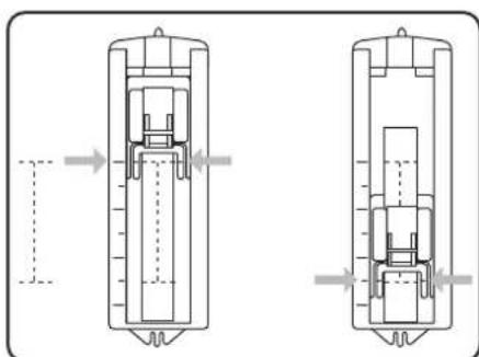
natural_image
Technical diagram of a mechanical component with two views, showing internal structure and alignment arrows (no text or symbols)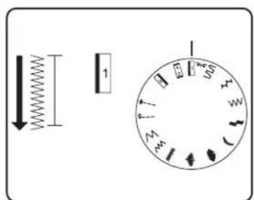
natural_image
Simple line drawing of a mechanical spring-loaded tool with no text or symbols10.12. Rimpelen
natural_image
Simple line drawing of a grid with diagonal lines and an arrow pointing upward (no text or symbols)natural_image
Diagram showing a screwdriver with directional arrows indicating motion (no text or symbols)i
natural_image
Diagram of a sewing machine needle with directional arrows indicating movement (no text or symbols)natural_image
Technical line drawing of a sewing machine needle and foot (no text or symbols)
natural_image
Diagram of a sewing machine needle and foot with a downward arrow indicating measurement or positioning (no text or symbols)11.2.2. Plaatsen
natural_image
Technical line drawing of a sewing machine needle with two screws and a base plate (no text or symbols)
natural_image
Line drawing of a sewing machine needle being inserted into a socket (no text or symbols)natural_image
Technical line drawing of a mechanical device with a circular component inserted, showing no text or symbols.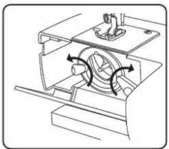
natural_image
Technical line drawing of a mechanical device with internal components and directional arrows (no text or symbols)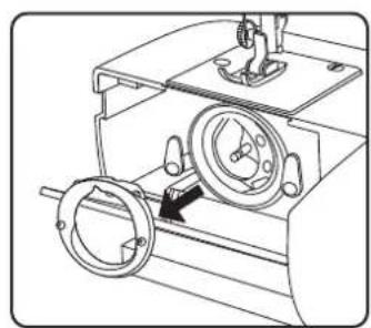
natural_image
Technical line drawing of a mechanical device with two circular components and a central dial (no text or symbols)natural_image
Technical line drawing of a mechanical assembly with a gear and housing (no text or symbols)natural_image
Technical line drawing of a mechanical assembly with no visible text or symbolsnatural_image
Technical line drawing of a mechanical device with no visible text or symbolsnatural_image
Mechanical assembly diagram showing a motor with rotating components and a highlighted shaft (no text or symbols)natural_image
Technical line drawing of a mechanical device with two circular components and a central hub (no text or symbols)natural_image
Technical line drawing of a sewing machine component with screws and fastener (no text or symbols)▶ Trek de frontklep (20) eraf.
natural_image
Technical line drawing of a sewing machine with a side view showing internal components (no text or symbols)
natural_image
Technical line drawing of a mechanical assembly with no visible text or symbols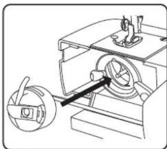
natural_image
Technical line drawing of a mechanical device with a rotating component and a handle (no text or symbols)natural_image
Diagram showing connection between a device with an attached switch and power strip (no text or symbols)
natural_image
Simple line drawing of a foot pressing down on a rectangular object, with no text or symbols present.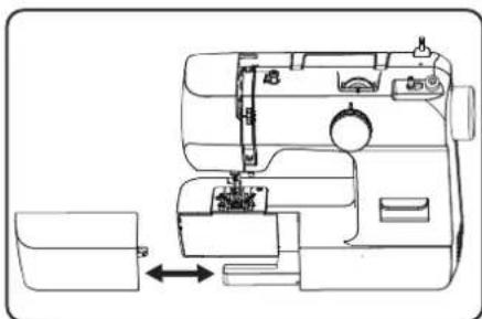
natural_image
Line drawing of a sewing machine with a side panel and internal components (no text or symbols)8. Trabajos previos
natural_image
Technical line drawing of a mechanical device with no visible text or symbolsnatural_image
Technical line drawing of a vehicle interior with labeled components and directional arrows (no text or symbols)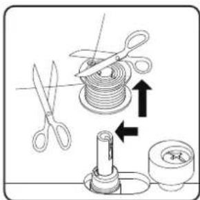
natural_image
Technical line drawing of a sewing machine with a black arrow indicating a component (no text or symbols present)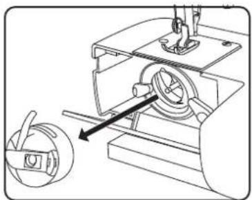
natural_image
Technical line drawing of a mechanical device with a rotating component and a separate view showing a curved arm (no text or symbols)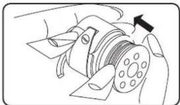
natural_image
Illustration of a hand operating a mechanical component with a black arrow indicating direction (no text or symbols present)
natural_image
Line drawing of a hand holding a small mechanical device with a downward arrow indicating motion (no text or symbols)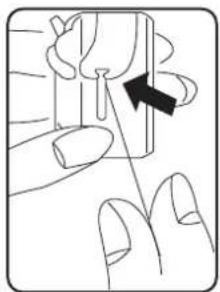
natural_image
Illustration of a finger pressing a button with an arrow indicating direction (no text or symbols)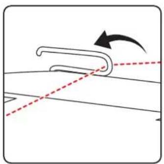
natural_image
Diagram showing a curved object with an arrow indicating rotation, intersected by two dashed lines (no text or symbols)natural_image
Diagram of a device with curved body and directional arrows indicating motion (no text or symbols)
natural_image
Diagram of airflow around a curved duct with motion arrows indicating direction (no text or symbols)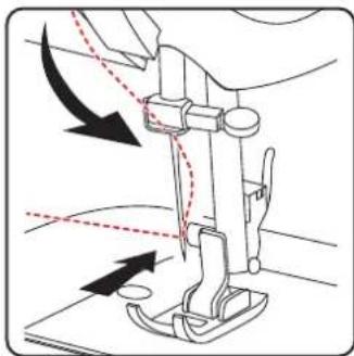
natural_image
Diagram of a sewing machine needle with arrows indicating force direction (no text or symbols)natural_image
Line drawing of a sewing machine handle with two vertical pins and a circular button (no text or symbols)natural_image
Diagram showing a curved mechanical component with dashed lines indicating alignment or movement, no text or symbols present.natural_image
Diagram of a car interior showing curved and dashed lines indicating movement or motion (no text or symbols)i
natural_image
Diagram showing fluid flow around a curved pipe with directional arrows (no text or symbols)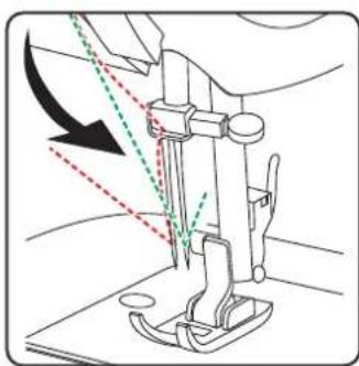
natural_image
Line drawing of a sewing machine needle with arrow indicating force direction (no text or symbols)8.10. Subida del hilo inferior
natural_image
Diagram of a sewing machine needle with directional arrows indicating movement (no text or symbols)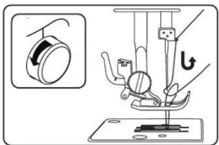
natural_image
Diagram of a sewing machine needle and fabric (no text or symbols)natural_image
Pure mechanical component diagram without any text, numbers, or symbols9.4.2. Costuras irregulares

natural_image
Technical line drawing of a sewing machine needle and base plate assembly (no text or symbols)10.4. Costura inversa
natural_image
Technical illustration of a sewing machine needle stitching on fabric, showing mechanical components and a close-up view (no text or symbols)10.8. Selector de programas

¡AVISO!
¡Peligro de daños!
natural_image
Diagram showing two steps of a mechanical or structural assembly with labeled points A (no text or symbols present)
natural_image
Line drawing of a sewing machine needle stitching fabric (no text or symbols)natural_image
Line drawing of a sewing machine needle and chain (no text or symbols)10.11. Ojales

CONSEJO
natural_image
Technical diagram of a mechanical assembly with two views showing internal components and directional arrows (no text or labels)
natural_image
Simple line drawing of a mechanical tool with spring and handle (no text or symbols)
natural_image
Simple line drawing of a hand holding a string above a grid with dashed lines (no text or symbols)10.12. Fruncido
natural_image
Diagram showing a screwdriver with a rotating head and a pointed tip, illustrating the mechanical process (no text or symbols)i
natural_image
Technical diagram of a sewing machine needle with directional arrows indicating movement (no text or labels)
natural_image
Technical line drawing of a sewing machine needle and foot (no text or symbols)
natural_image
Diagram of a sewing machine needle and foot with a downward arrow indicating measurement or positioning (no text or symbols)11.2.2. Colocación
natural_image
Technical line drawing of a sewing machine needle with two screws and a base plate (no text or symbols)natural_image
Line drawing of a sewing machine needle stitching into a circuit board (no text or symbols)▶ Vuelva a colocar la placa de la aguja.
natural_image
Technical line drawing of a mechanical device with a circular component inserted, showing no text or symbols.natural_image
Technical line drawing of a mechanical device with internal components and directional arrows indicating motion (no text or symbols)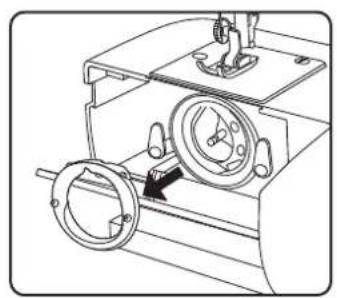
natural_image
Technical line drawing of a mechanical device with two circular components and a central hub (no text or symbols)natural_image
Technical line drawing of a mechanical assembly with no visible text or symbolsnatural_image
Technical line drawing of a mechanical assembly with no visible text or symbolsnatural_image
Technical line drawing of a mechanical device with a central rotating component and mounting base (no text or symbols)natural_image
Technical line drawing of a mechanical assembly with no visible text or symbolsnatural_image
Technical line drawing of a mechanical device with rotating components and a directional arrow (no text or symbols)natural_image
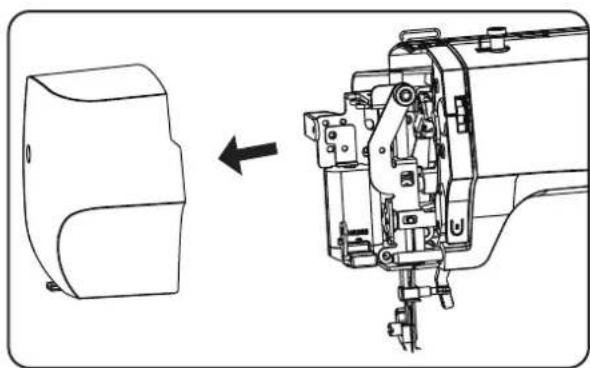
Technical line drawing of a sewing machine component with screws and fastener (no text or symbols)▶ Retire la cubierta frontal (20).
natural_image
Technical line drawing of a sewing machine with a side view showing internal components (no text or symbols)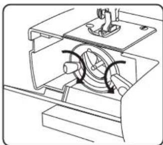
natural_image
Technical line drawing of a mechanical assembly with no visible text or symbols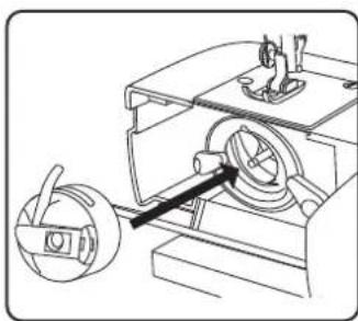
natural_image
Technical line drawing of a mechanical device with a circular component inserted into a housing (no text or symbols)MEDION Service Center
ENAME, S.A
natural_image
Diagram showing connection between a device with an attached switch and a flatboard, no text or symbols present
natural_image
Line drawing of a foot pressing down on a wooden block, with an arrow indicating motion (no text or symbols)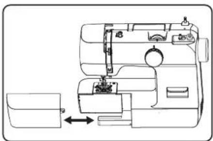
natural_image
Line drawing of a sewing machine with a side panel and internal components (no text or symbols)natural_image
Technical line drawing of a mechanical device with no visible text or symbolsnatural_image
Technical line drawing of a mechanical device interior with no visible text or symbols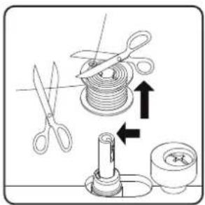
natural_image
Technical line drawing of a mechanical assembly with a rotating component and directional arrow (no text or symbols)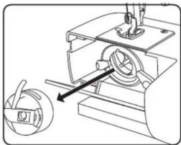
natural_image
Mechanical assembly diagram showing a sewing machine with a rotary knob and mechanical components (no text or labels)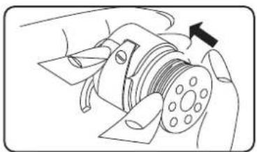
natural_image
Diagram of a mechanical device with a rotating shaft and housing, showing no text or symbols.
natural_image
Line drawing of a hand holding a small mechanical component with a downward arrow indicating motion (no text or symbols)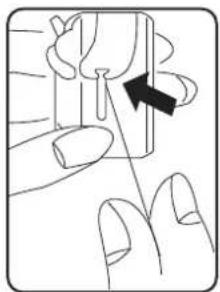
natural_image
Illustration of a finger pressing down on a small object with an arrow indicating direction (no text or symbols)
natural_image
Diagram showing a curved mechanical component with an arrow indicating rotation, no text or symbols presentnatural_image
Diagram of a device with curved body and directional arrows indicating motion (no text or symbols)
natural_image
Diagram of airflow around a curved duct with motion arrows indicating direction (no text or symbols)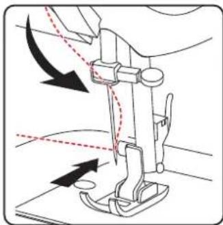
natural_image
Diagram of a sewing machine needle with arrows indicating force direction (no text or symbols)natural_image
Line drawing of a sewing machine handle with two vertical pins and a circular button (no text or symbols)natural_image
Diagram showing a curved pipe or tube with dashed lines indicating motion, no text or symbols presentnatural_image
Diagram of a car interior showing airflow path with arrows indicating direction (no text or labels)i
natural_image
Diagram showing a curved mechanical component with dashed and dotted lines indicating motion or flow, no text or symbols present.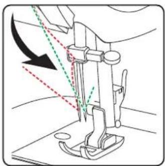
natural_image
Line drawing of a sewing machine needle with arrow indicating force direction (no text or symbols)natural_image
Diagram of a sewing machine needle with directional arrows indicating movement (no text or labels)
natural_image
Diagram of a sewing machine needle and fabric tray (no text or symbols)natural_image
Pure mechanical component diagram without any text, numbers, or symbols

natural_image
Technical line drawing of a sewing machine needle and base, showing mechanical components and a close-up inset (no text or symbols)natural_image
Diagram of a sewing machine needle stitching fabric, showing step and side views (no text or symbols)10.7. Taglio del fi lo
natural_image
Line drawing of a hand inserting a small electronic component into a device (no text or symbols visible)natural_image
Five abstract wavy line patterns arranged horizontally (no text or symbols)natural_image
Diagram showing two steps of a curved cable or wire installation on a panel, with no visible text or symbols.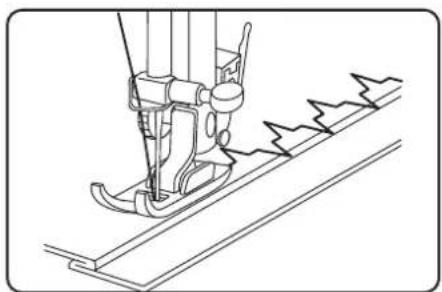
natural_image
Line drawing of a sewing machine needle stitching fabric (no text or symbols)10.10.5. Punto elastico
natural_image
Technical line drawing of a sewing machine needle and chain (no text or symbols)10.11. Asole

CONSIGLIO
natural_image
Technical diagram of a mechanical assembly with two views showing internal components and directional arrows (no text or labels)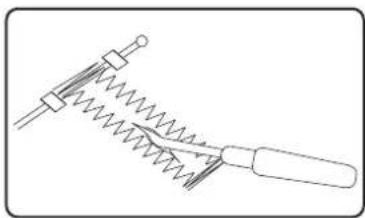
natural_image
Pure mechanical diagram of a spring-loaded tool with no text or symbols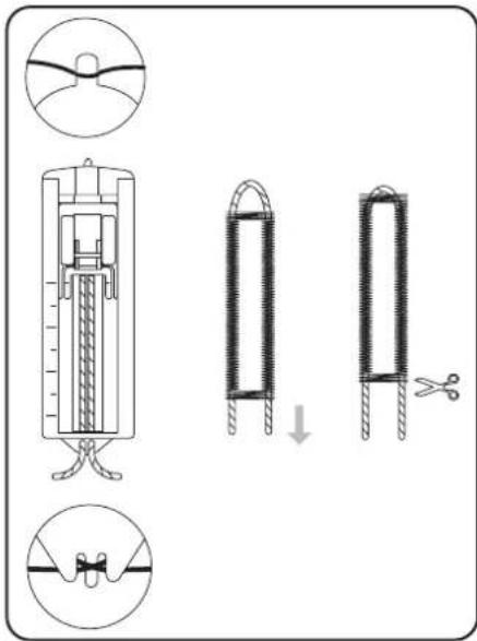

natural_image
Simple line drawing of a hand holding a string above a grid with dashed lines (no text or symbols)10.12. Increspature
natural_image
Diagram showing a screwdriver with directional arrows indicating motion (no text or symbols)
natural_image
Diagram of a sewing machine needle with directional arrows indicating movement (no text or symbols)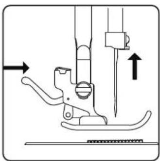
natural_image
Technical diagram of a sewing machine needle and screw base mechanism (no text or labels)
natural_image
Diagram of a sewing machine needle and foot with a downward arrow indicating measurement or positioning (no text or symbols)11.2.2. Inserimento
natural_image
Technical line drawing of a sewing machine needle with two screws and a base plate (no text or symbols)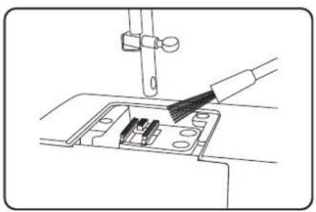
natural_image
Line drawing of a sewing machine needle stitching into a circuit board (no text or symbols)▶ Riposizionare la placca d'ago.
natural_image
Technical line drawing of a mechanical device with a circular component inserted, showing internal components and a directional arrow (no text or symbols)natural_image
Mechanical assembly diagram showing a rotating component with directional arrows (no text or labels)
natural_image
Technical line drawing of a mechanical device with two circular components and a central dial (no text or symbols)natural_image
Mechanical assembly diagram showing a motor with rotating components and a gear mechanism (no text or labels)natural_image
Technical line drawing of a mechanical device with no visible text or symbolsnatural_image
Technical line drawing of a mechanical device with no visible text or symbolsnatural_image
Mechanical assembly diagram showing a motor with rotating components and a gear mechanism (no text or labels)natural_image
Technical line drawing of a sewing machine with a circular component and mechanical parts (no text or symbols)natural_image
Technical line drawing of a sewing machine component with screws and fastener (no text or symbols)natural_image
Technical line drawing of a mechanical assembly with an arrow indicating direction (no text or symbols present)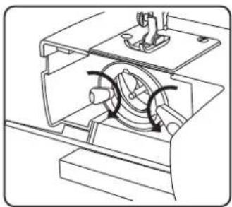
natural_image
Technical line drawing of a mechanical assembly with internal components and motion arrows (no text or symbols)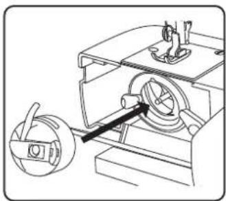
natural_image
Technical line drawing of a mechanical device with a rotating knob and housing (no text or symbols)- About this user manual....189
1.1. Explanation of symbols....189
-
Proper use ....189
-
Declaration of conformity ....189
-
Safety instructions....190
4.1. Keep children away from electrical appliances 190
4.2. Mains cable and power supply 190
4.3. General information....190
4.4. Never carry out repairs yourself....190
4.5. Handle the appliance with care....190
4.6. Cleaning and storage 191
-
Package contents.... 191
-
Appliance overview....192
-
Electrical connections ......195
7.1. Controlling the sewing speed....195
7.2. Attaching and removing the extension table....195
- Preparatory work....196
8.1. Fitting a spool ....196
8.2. Winding thread onto the bobbin .....196
8.3. Removing the bobbin case....197
8.4. Threading the bobbin case ....197
8.5. Inserting the bobbin case....198
8.6. Threading the upper thread .....198
8.7. Illustration of the upper thread guide ....199
8.8. Threading the upper threads on twin needles....200
8.9. Illustration of the upper thread guide 201
8.10. Bringing up the bobbin thread 202
- Settings 203
9.1. Setting the thread tension....203
9.2. Adjusting the upper thread tension 203
9.3. Adjusting the bobbin thread tension....203
9.4. Checking the thread tension 204
- Sewing....205
10.1. General information....205
10.2. Selecting the right needle .....205
10.3. Raising and lowering the presser foot....205
10.4. Reverse stitching 206
10.5. Removing fabric from the sewing machine....206
10.6. Changing the sewing direction....206
10.7. Cutting the thread....206
10.8. The program selection dial ....206
10.9. Stitch length adjustment....207
10.10. Stitch type settings 207
10.11. Buttonholes....209
10.12. Gathering 211
10.13. Sewing with the free arm....211
10.14. Sewing with a twin needle....212
- Maintenance, care and cleaning 213
11.1. Replacing the needle 213
11.2. Removing and fitting the presser foot 213
11.3. Removing and fitting the presser foot holder.... 214
11.4. Maintaining the sewing machine 214
11.5. Oiling the machine 217
- Faults....219
12.1. Fabric, thread and needle table....220
12.2. Useful sewing tips....221
13. Technical specifications....221
14. Disposal....221
15. Service information....222
16. Legal Notice....222
1. About this user manual

Thank you for choosing our product. We hope you enjoy using this appliance.
Read the safety instructions carefully before using the appliance for the first time. Note the
warnings on the appliance and in the user manual.
Always keep the user manual close to hand. If you sell the appliance or give it away, please ensure that you also pass on this user manual. It is an essential component of the product.
1.1. Explanation of symbols
If a block of text is marked with one of the warning symbols listed below, the hazard described in that text must be avoided to prevent the potential consequences described there from occurring.

DANGER!
Warning: risk of fatal injury!
WARNING!
Warning: risk of possible fatal injury and/or serious irreversible injuries!

CAUTION!
Warning: risk of minor and/or moderate injuries!

NOTICE!
Follow these instructions to prevent damage to the appliance!

More detailed information about using the appliance!
Follow the instructions in the user manual!

TIP
Sewing tips to make work easier

Symbol for protection class II

Indoor use
2. Proper use
Your appliance can be used in a range of ways:
The sewing machine can be used to sew together and embellish seams on light to heavy-weight material.
The material can be made of textile fibres, composite materials or lightweight leather.
- The appliance is only intended for private use and not for industrial/commercial use.
- Please note that we shall not be liable in cases of improper use:
- Do not modify the appliance without our consent and do not use any auxiliary equipment that we have not approved or supplied.
- Only use replacement parts or accessories that we have supplied or approved.
- Comply with all the information in this user manual, especially the safety instructions. Any other use is considered improper and can cause personal injury or property damage.
- Do not use the device in extreme environmental conditions.
3. Declaration of conformity
Medion AG hereby declares that the product conforms to the following European requirements:
• EMC Directive 2014/30/EU
• Low Voltage Directive 2014/35/EU
• Ecodesign Directive 2009/125/EC
• RoHS Directive 2011/65/EU

4. Safety instructions
4.1. Keep children away from electrical appliances
- This appliance can be used by children of 8 years and older, and by people with reduced physical, sensory or mental capacity, or with a lack of experience and/or knowledge, but only with proper supervision, or if they have been told how to use the appliance safely, and have understood the risks involved if they use it improperly. Children must not be allowed to play with the appliance. Do not allow children to clean the appliance or perform maintenance tasks on it unless they are aged 8 years or older, and properly supervised.
- Do not allow children younger than 8 years old near the appliance and its power cable.
DANGER!
Risk of choking and suffocation!
Packaging film can be swallowed or used improperly, creating a risk of choking and suffocation.
- Keep packaging material such as plastic film or plastic bags away from children.
4.2. Mains cable and power supply
- Only connect the appliance to an easily accessible socket (220–240 V \~ 50 Hz) that is close to where you have set up the appliance. The power socket must be easily accessible so that you can unplug the appliance from the mains quickly if necessary.
- When unplugging, always hold the plug itself and never pull on the cable.
- Fully unwind the cable during use.
- You must position the mains cable and extension cable so that no one can trip over them.
- The cable may not touch any hot surfaces.
- If you leave the sewing machine unattended, unplug the mains plug to prevent accidents due to unintentional start-up of the machine.
- Switch off the sewing machine and unplug the mains plug for the following tasks: threading the needle, replacing the needle, setting the presser foot, cleaning and maintenance work, at the end of sewing work and when work is interrupted.
4.3. General information
- The sewing machine must not get wet – there is a risk of electric shock!
- Never leave the sewing machine unattended when switched on.
- Do not use the sewing machine outdoors.
- Do not use the sewing machine when damp or in damp environments.
- The appliance may only be operated with the supplied type HKT72C foot control pedal.
4.4. Never carry out repairs yourself
WARNING!
Risk of electric shock!
There is a risk of electric shock if repairs are not carried out by qualified personnel!
■ Never attempt to open or repair the appliance yourself.
In the event of a fault or damage to the power cable, contact our Service Centre or another suitable professional repair workshop to prevent hazards.
- If the appliance or power cable is damaged, remove the mains plug from the socket immediately.
- If there is visible damage to the sewing machine, or power cable, the appliance may not be used. This is to avoid hazards.
4.5. Handle the appliance with care
- Place the sewing machine on a sturdy, level work surface.
- When the appliance is in use, the ventilation openings must remain free: do not allow any foreign objects (e.g. dust, pieces of thread etc.) to get into the openings.
-
Keep the foot control pedal free from fluff, dust and offcuts of fabric.
-
Never place anything onto the foot control pedal.
- Use only the supplied accessories.
- Only use specialist sewing machine oil to lubricate the machine. Do not use any other liquids.
- Take care when operating the moving parts of the machine, particularly the needle. There is also risk of injury when the machine is not connected to the power supply!
- When sewing, ensure that you do not place your fingers under the needle clamp screw.
- Do not use bent or blunt needles.
- When sewing, do not hold the fabric tight and do not pull on the fabric. This could cause the needle to break.
• Always place the needle in the highest position at the end of sewing work. - When leaving the machine and before maintenance work, always switch off the machine and pull the mains plug from the socket.
4.6. Cleaning and storage
- Before cleaning, pull the plug out of the mains socket.
- Use a soft, damp cloth to clean the appliance.
- Avoid the use of chemical solutions and cleaning products because these may damage the appliance surface and/or the labels on it.
- Store the machine in a dry place away from children. Always cover the sewing machine with the enclosed cover to protect it from dust.
5. Package contents
DANGER!
Risk of choking and suffocation!
Packaging film can be swallowed or used improperly, creating a risk of choking and suffocation.
- Keep packaging material such as plastic film or plastic bags away from children.
Please check the package contents to ensure that all items are included. If anything is missing, please contact us within 14 days of purchase.
- Sewing machine
- Foot control, type HKT72C
- Accessories in the accessory box (overview of contents on the following page)
- Short manual
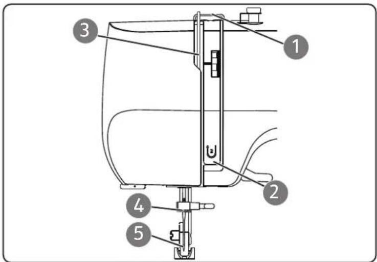
6. Appliance overview
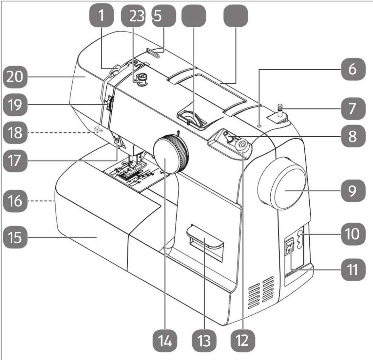
Fig. 1 - Appliance overview
- Thread take-up
- Bobbin-winding thread guide
- Upper thread guide
- Stitch length control
- Folding carry handle
- Opening for optional spool holder
- Spool holder
- Bobbin spindle
- Handwheel
-
Connector housing for mains plug
-
Main switch (motor and light)
- Winding stop
- Reverse lever
- Program selection dial
- Extension table
- Bobbin case (behind the extension table)
- Front thread guide
- Thread cutter (on the rear)
- Upper thread tension regulator
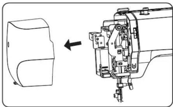
- Front cover
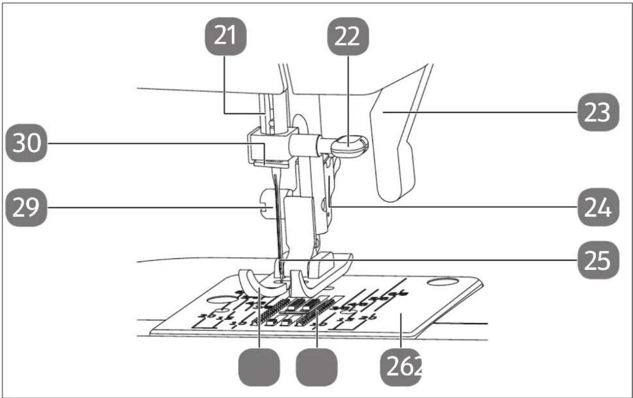
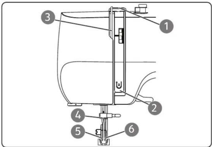
Fig. 2 - Sewing mechanics
- Needle bar
- Needle clamp screw
- Presser foot lever
- Presser foot release lever (at the rear)
-
Needle
-
Needle plate
- Fabric feeder
- Presser foot
- Sewing foot holding screw
- Thread guide
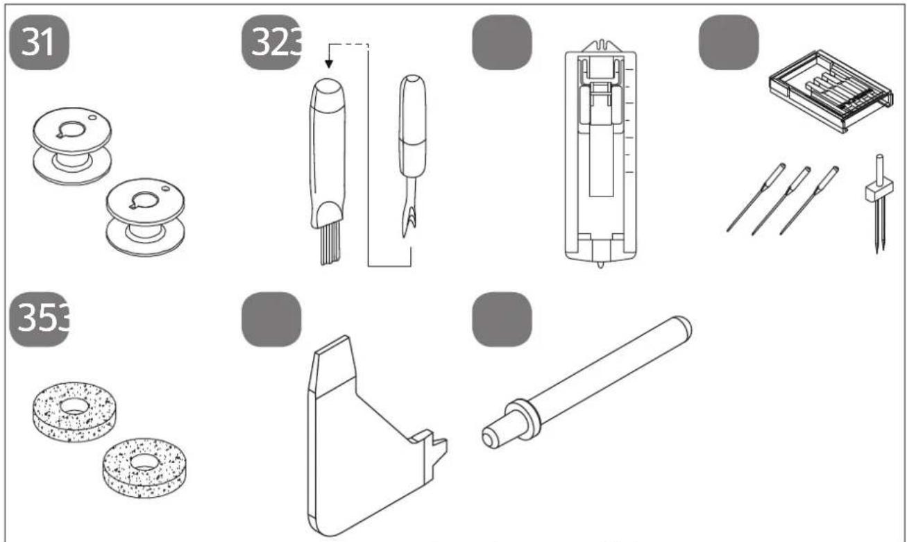
Fig. 3 – Accessories (bag in the extension table)
- 3 bobbins (2 in the accessory compartment and 1 pre-assembled)
- Lint brush with seam ripper
- Buttonhole presser foot
- Needle box with contents:
3 needles 90/14
1 twin needle
- Felt gliders for spool holders
- Multi-functional screw driver
- Optional spool holder
not illustrated
- Standard foot (straight stitch/zigzag stitch) (already attached)
- Cover
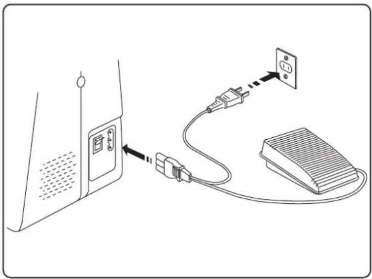
7. Electrical connections

CAUTION!
Risk of injury!
There is a risk of injury from accidental operation of the foot control pedal.
■ After finishing work or before maintenance work, always switch off the machine and unplug the mains plug from the socket.
Plug the coupling connector on the mains cable supplied into the connector housing (10) on the machine.
▶ Plug the mains plug into the socket.
Switch on the sewing machine using the mains switch (11). The mains switch turns on both the sewing machine and the sewing light.
natural_image
Diagram showing connection between a device with an attached plug and power strip, no text or symbols present
Use only the supplied type HKT72C foot control pedal.
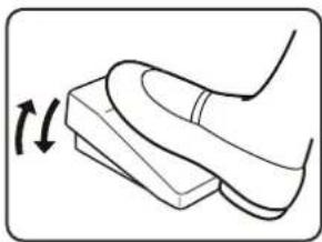
7.1. Controlling the sewing speed
The sewing speed is controlled using the foot control pedal.
This means that the sewing speed can be changed by exerting more or less pressure on the foot control.
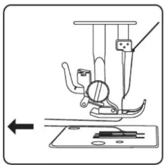
7.2. Att aching and removing the extension table
The machine is supplied with an attached extension table (15).
The extension table is removed by pushing it carefully to the left.
To attach the extension table, carefully place the extension table onto the machine and push it to the right until it audibly clicks into place.
natural_image
Line drawing of a foot pressing down on a wooden block, with an arrow indicating motion (no text or symbols)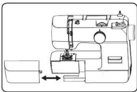
natural_image
Line drawing of a sewing machine with a side panel and internal components (no text or symbols)8. Preparatory work
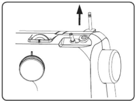
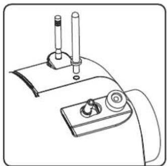
8.1. Fitting a spool

TIP
Most spools have a notch to hold the thread in place after use. Make sure that this notch is pointing downwards in order to ensure that the thread will run evenly and will not catch.
natural_image
Technical line drawing of a mechanical device with no visible text or symbols▶ Pull the spool holder (7) up out of the machine until it audibly clicks into place.
Place the spool onto the spool holder.
8.2. Winding thread onto the bobbin
Bobbins can be wound onto the sewing machine quickly and easily.
To do this, guide the thread from the spool through the bobbin-winding thread guide (2) to the bobbin.
The exact procedure for winding thread onto the bobbin is described in the following points:
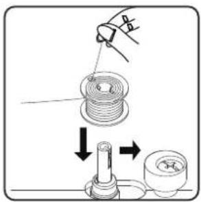
Place the spool onto the spool holder.
▶ Guide the thread from the spool around the bobbin-winding thread guide as shown in the diagram.
▶ Feed the end of the thread through the hole in the bobbin and wind the thread around the bobbin a few times by hand.
natural_image
Technical line drawing of a vehicle interior with labeled components and directional arrows (no text or symbols)Place the bobbin on the spindle (8) with the end of the thread facing upwards to the bobbin. Move the bobbin spindle to the right towards the winding stop (12) until it audibly clicks into place.
Hold the end of the thread firmly and press the foot control pedal. Once some thread has been wound onto the bobbin, let go of the end of the thread. Wind until the bobbin spindle stops turning.
i
Once the bobbin spindle has been moved to the right, the sewing mechanism is disabled so that the needle does not move while the thread is being wound onto the bobbin.
▶ Move the bobbin spindle to the left and remove the bobbin.
▶ Cut off excess threads.
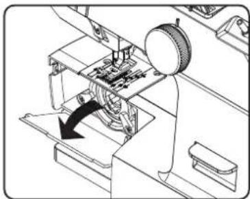
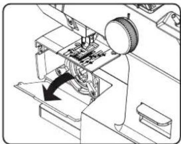
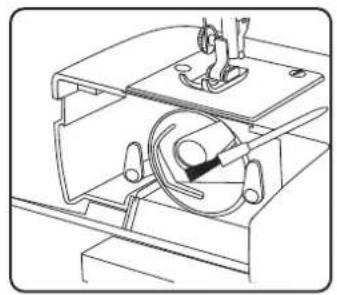
8.3. Removing the bobbin case
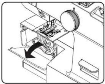
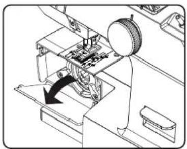
▶ Remove the extension table.
▶ Set the needle (25) by turning the handwheel (9) and the presser foot to the top position and open the bobbin case (16) behind the extension table (15) as shown in the diagram.
▶ Open the bobbin case toggle lever and pull it out of the machine.
When you release the toggle lever, the bobbin falls out of the bobbin case by itself.
8.4. Threading the bobbin case
▶ Hold the bobbin between the thumb and index finger of your right hand and pull the thread approx. 15 cm out of the bobbin.
Hold the bobbin case in your left hand and insert the bobbin into the bobbin case.
Insert the end of the thread into the slot on the edge of the bobbin case.

natural_image
Technical line drawing of a mechanical assembly with a rotating component and directional arrow (no text or symbols)
natural_image
Mechanical assembly diagram showing a sewing machine with a rotary knob and mechanical components (no text or labels)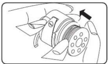
natural_image
Diagram of a hand operating a mechanical component with a circular component and an arrow indicating direction (no text or symbols present)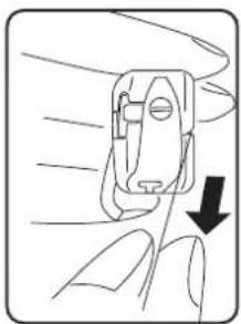
natural_image
Line drawing of a hand holding a small mechanical component with a downward arrow indicating force or direction (no text or symbols)
natural_image
Illustration of a finger pressing down on a small object with an arrow indicating direction (no text or symbols)Now guide the thread under the tension spring and into the thread hole. Make sure that the end of the thread is approx. 15 cm long.

Check that the bobbin is inserted correctly and can be turned clockwise in the capsule.
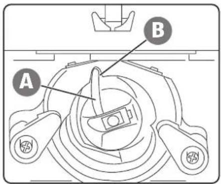
8.5. Inserting the bobbin case
- Hold the bobbin case so that the finger (A) of the case is pointing upwards.
▶ Open the bobbin case toggle lever.
Place the bobbin case on the centre pin and press the bobbin case in carefully until the finger of the bobbin case enters the recess (B) in the shuttle track ring.
Release the toggle lever and press it onto the bobbin case.
▶ Close the bobbin case (16).
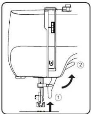
8.6. Threading the upper thread
Please read the following instructions carefully as an incorrect sequence or thread guiding can lead to broken threads, missed stitches and gathered fabric.
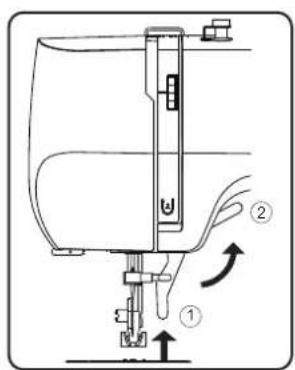
Before threading the needle, raise the needle to its top position by turning the handwheel.
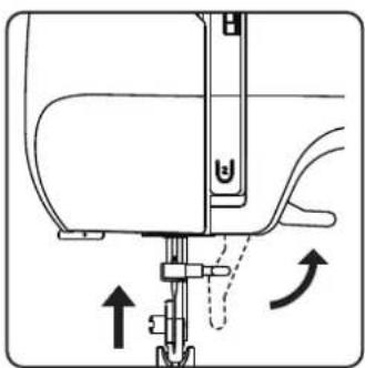
▶ Also move the presser foot lever (23) to the upper position (2). This releases the thread tension and allows the upper thread to be threaded in easily.

natural_image
Diagram showing a curved mechanical component with an arrow indicating rotation, no text or symbols presentPlace a spool onto one of the spool holders.
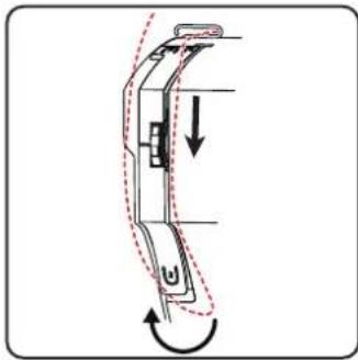
Now pass the thread through the upper thread guide (3).
▶ Then allow the thread to pass between the tension discs of the upper thread tension regulator (19). Guide the thread upwards under the front thread guide and the inner guide spring is automatically pushed upwards.
i
Unlike most sewing machines, the tension discs of the upper thread tension regulator are not directly visible. Therefore, be very careful that the thread lies between the tension discs and does not run through the machine anywhere else.
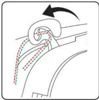
Then insert the thread from right to left into the hook of the of the thread take-up (1).
i
If necessary, turn the handwheel to raise the thread take-up.
Now guide the thread back down towards the needle.
▶ Guide the thread through the thread guide of the needle holder (28).
▶ Finally pass the thread through the eye of the needle.
natural_image
Diagram of a mechanical device with curved body and directional arrows indicating motion (no text or symbols)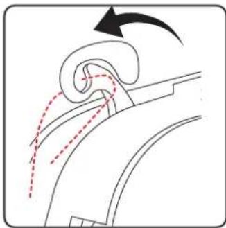
natural_image
Diagram of a curved mechanical component with motion arrows indicating movement (no text or symbols)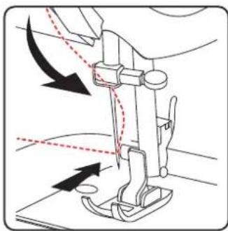
natural_image
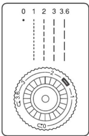
Diagram of a sewing machine needle with arrows indicating fabric direction (no text or symbols)8.7. Illustration of the upper thread guide
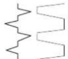
For a better overview, you will find a schematic representation of the thread path of the upper thread here.
The numbers indicate the sequence of steps in the threading process.
You will also find the first three numbers on the sewing machine.
8.8. Threading the upper threads on twin needles
Please read the following instructions carefully as an incorrect sequence or thread guiding can lead to broken threads, missed stitches, gathered fabric and needle breakage.
Before threading the needle, raise the needle to its top position by turning the handwheel.
▶ Also move the presser foot lever to the upper position (2). This releases the thread tension and allows the upper thread to be threaded in easily.
natural_image
Line drawing of a mechanical device with two cylindrical components and a base panel (no text or symbols)Insert the optional spool holder (37) into the opening (6) provided on the top of the sewing machine.
Place a spool onto one of the spool holders.
i
Repeat the following steps for each upper thread separately.
Now pass the thread through the upper thread guide.
natural_image
Diagram showing a curved mechanical component with dashed lines indicating alignment or motion, no text or symbols present.▶ Then allow the thread to pass between the tension discs of the upper thread tension regulator.
Guide the thread upwards under the front thread guide and the inner guide spring is automatically pushed upwards.
i
Unlike most sewing machines, the tension discs of the upper thread tension regulator are not directly visible. Therefore, be very careful that the thread lies between the tension discs and does not run through the machine anywhere else.
▶ Then insert the thread from right to left into the hook of the thread take-up.
i
If necessary, turn the handwheel to raise the thread take-up.
Now guide the thread back down towards the needle.
▶ Guide the thread of the first spool through the thread guide of the needle holder.
▶ Finally, thread the first thread through the eye of the left needle.
The thread for the right needle does not have to be fed through the thread guide of the needle holder; the thread can be threaded directly into the eye of the right needle.

natural_image
Diagram showing fluid flow around a curved pipe with directional arrows (no text or symbols)
natural_image
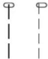
Line drawing of a sewing machine needle with arrow indicating force direction (no text or symbols)8.9. Illustration of the upper thread guide
For a better overview, you will find a schematic representation of the thread path of the upper thread here.
The numbers indicate the sequence of steps in the threading process.
You will also find the first three numbers on the sewing machine.
natural_image
Technical diagram of a sewing machine needle and screw mechanism (no text or labels)
natural_image
Diagram of a sewing machine needle and fabric tray with no visible text or symbols8.10. Bringing up the bobbin thread
▶ Move the presser foot (28) to the upper position.
▶ Turn the handwheel towards you with your right hand until the needle is in the upper position.
Hold the upper thread loosely with your left hand and turn the handwheel towards you with your right hand until the needle has moved down and back up again.
Stop turning the handwheel as soon as the needle has reached its highest position.
▶ Pull the upper thread upwards slightly so that the bobbin thread forms a loop.
▶ Pull around 15 cm of both threads out and back from under the presser foot.
9. Sett ings
9.1. Sett ing the thread tension
If the thread tears while you are sewing, the thread tension is too high. If small loops are formed when you are sewing, the thread tension is too low.
In both cases, you need to set the thread tension.
The tensions of the upper thread and bobbin thread must be in the correct proportion to each other.
9.2. Adjusting the upper thread tension
i
An upper thread tension of 3–4 is suitable for most sewing work.
The tension is created by the discs through which the thread is guided. The pressure on these discs is controlled by the upper thread tension regulator (19).
The higher the number, the higher the tension.
The upper thread tension is not activated until the presser foot is lowered.
There are a number of reasons why you might need to adjust the tension.
For example, different tensions are required for different fabrics.
The tension required depends on the strength and thickness of the fabric, the number of layers of fabric you want to sew and the type of stitch you choose.
Please make sure that the tensions of the upper thread and bobbin thread match, as otherwise the fabric may gather.
We recommend that you carry out a test on a scrap of fabric before starting work.
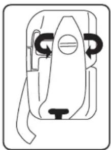
9.3. Adjusting the bobbin thread tension
The tension of the bobbin thread is regulated by the spring on the bobbin case.
▶ Turn the spring screw clockwise to increase the thread tension.
▶ Turn the spring screw anti-clockwise to reduce the thread tension.
natural_image
Pure mechanical component diagram without any text, numbers, or symbols9.4. Checking the thread tension
9.4.1. Correct stitching
The correct setting of upper and bobbin thread tension is achieved when the interlacing of the threads is in the centre of the fabric.
The fabric remains smooth and does not pucker.
9.4.2. Incorrect stitching
The upper thread is too tight and pulls the bobbin thread up. The bobbin thread is visible on the upper fabric layer.
Solution:
Reduce the upper thread tension by turning the upper thread tension regulator to a lower number.

Upper thread is too loose. The bobbin thread pulls the upper thread down. The upper thread is visible on the underside of the fabric layer.
Solution:
Increase the upper thread tension by turning the upper thread tension regulator to a higher number.
10. Sewing
10.1. General information
- Switch on the main switch (11).
- When changing the stitch type, always move the needle to its highest position.
- Push the fabric sufficiently far under the presser foot (28). Make sure there is a length of around 10cm of upper thread and bobbin thread behind the needle.
- Lower the presser foot lever (23). Holding the thread with your left hand, turn the handwheel (9) towards you and lower the needle to the point on the fabric where you want to start sewing.
- Press the foot control pedal – the further the foot control pedal is pressed, the faster the machine runs. While sewing, guide the fabric gently by hand.
- Sew a few reverse stitches by actuating the reverse lever (13) to fix the first stitches in place.

TIP
If you are not sure whether the thread tension or stitch type, for example, is correct, test the settings on a swatch.
The fabric will run through automatically under the presser foot. It should not be held fast or pulled by hand, but should only be gently guided so that the stitches go in the desired direction.
10.2. Selecting the right needle

NOTICE!
Risk of damage!
Using a defective needle can cause damage to the material.
■ Replace defective needles immediately.
The number indicating the needle thickness is written on the shaft. The higher the number, the thicker the needle.
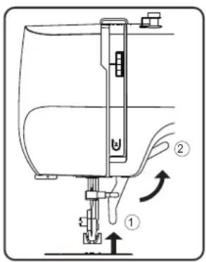
10.3. Raising and lowering the presser foot
Raising or lowering the presser foot lever moves the presser foot up or down accordingly.
Position 1: The presser foot presses the fabric onto the feeders, the thread tension is activated.
You can start sewing.
Position 2: The presser foot is in the top position and the thread tension is released.
You can take the fabric out of the machine, put it in the machine, or change the presser foot.
natural_image
Technical line drawing of a sewing machine needle and base plate assembly (no text or symbols)10.4. Reverse stitching
Use reverse stitches to reinforce the first and last stitches on a seam.
▶ Press the reverse lever and hold it down.
- Press the foot pedal – the more pressure you apply to the foot pedal, the faster the machine will run.
When you want to change back to forward stitching, simply release the reverse lever.
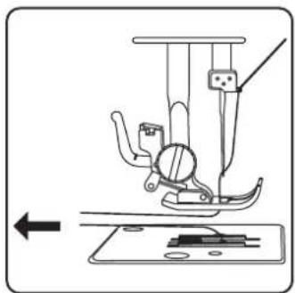
10.5. Removing fabric from the sewing machine
When you finish sewing, make sure that the needle is at its highest position.
▶ To remove the fabric, raise the presser foot and pull the fabric away from you out of the machine.
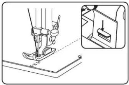
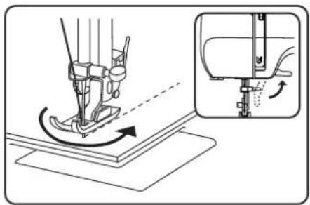
10.6. Changing the sewing direction
Proceed as follows to change direction when you reach the corners of the material:
▶ Stop the machine and turn the handwheel towards you until the needle is in the fabric.
▶ Raise the presser foot.
▶ Pivot the fabric around the needle to change the direction as desired.
▶ Lower the presser foot again and continue sewing.
natural_image
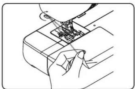
Technical illustration of a sewing machine needle stitching on a base, with an inset showing the same mechanism (no text or symbols present)10.7. Cutting the thread
Cut the thread using the thread cutter (18) on the back of the sewing machine or using scissors. Leave around 15 cm of the thread hanging behind the eye of the needle.
natural_image
Line drawing of a hand inserting into a device into a package (no text or symbols)10.8. The program selection dial
NOTICE!
Risk of damage!
The program selection dial cannot be rotated 360irc . Overwinding the dial may damage the mechanism.
■ Do not turn the programme selector beyond the respective end point markings "→" and "←"
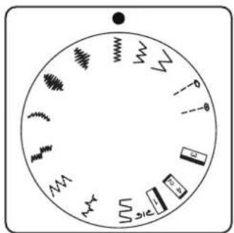
On this sewing machine, you can select a number of different functional and decorative stitches. You can use the program selection dial (14) to simply select the stitch pattern you want.
Before changing the stitch, always make sure that the needle is at its highest position.
▶ Turn the program selection dial so that the marker is lined up with the stitch type you want to use.
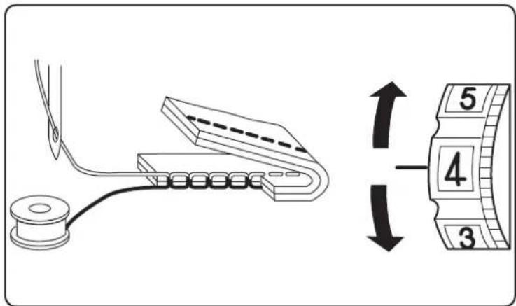
10.9. Stitch length adjustment
You can use the stitch length control (4) to select the length of the stitch pattern you have set.
▶ Turn the stitch length control so that the number of the desired stitch length is at the marking.
The numbers show the approximate stitch length in millimetres.
The program selection dial is used to set the stitch types. Make sure that the needle is at its highest position before changing the stitch type.
Always test the stitching on a swatch before using a stitch program for your actual work.

For instructions on attaching and removing the presser foot, please see "11.2. Removing and fitting the presser foot" on page 213.
10.10.1. Straight stitch
Suitable for general sewing and for top-stitching.
Presser foot: Standard foot
Stitch length: 0 to 3.6
10.10.2. Zigzag stitch

TIPS FOR ZIGZAG STITCHES
For better results when using zigzag stitch, the upper thread tension must be lower than when sewing straight stitches.
The upper thread should be slightly visible on the underside of the fabric.
The zigzag stitch is one of the most commonly used stitches. It can be used for many different things, for example hemming, appliqué and monograms.
Before you use the zigzag stitch, sew a few straight stitches to reinforce the stitching.
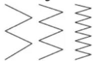
Presser foot: Standard foot
Stitch length:....1 to 3.6
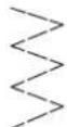
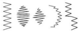
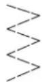
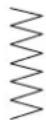
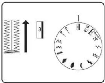
10.10.3. Satin stitch
natural_image
Five abstract wavy line patterns arranged horizontally (no text or symbols)So-called satin stitch, a zigzag stitch in which the stitches are very close together, is particularly suitable for appliqué, monograms, and various decorative stitches.
Presser foot: Standard foot
Stitch length: 0 to 1
TIP
Whenever you use this stitch, reduce the upper thread tension slightly. The wider the stitch, the lower the upper thread tension should be. If you are sewing very thin or soft fabrics, you should place a thin piece of paper under the fabric and sew this too. This prevents stitches being missed and the material gathering.
10.10.4. Blind stitch
TIP
Sewing blind stitch requires some practice and should be practised on remnants of fabric before sewing.
For blind hemming.
Presser foot: Standard foot
Stitch length: 0 to 3.6
Use a thread colour that exactly matches the fabric.
If you are sewing very light or transparent fabrics, use a transparent nylon thread.
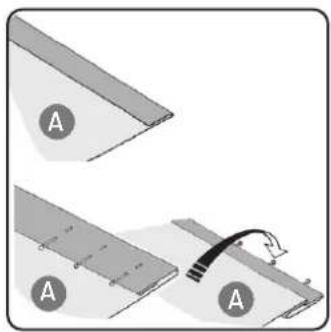
Place the fabric down in front of you with the top facing down.
▶ Fold the seam allowance onto the underside of the fabric (A), as shown in the diagram.
Now fold the hem allowance onto the underside as well and pin the seam allowance and hem allowance in place (see diagram opposite).
Then fold the entire blind hem over at the edge of the fabric, as illustrated in the diagram. The edge of the fabric should overlap the seam allowance slightly.
natural_image
Diagram showing two steps of a cable or cable installation on a panel, with no visible text or symbols.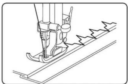
natural_image
Line drawing of a sewing machine needle stitching fabric (no text or symbols)▶ Sew carefully along the fold, making sure that the straight stitches are sewn on the hem and that the tips of each of the zigzag stitches only pierce the top fold of the fabric. Now take the fabric out of the machine and straighten it out. The folded-out fabric now has a blind hem stitch.
10.10.5. Stretch stitch
This stitch is particularly suitable for sewing two pieces of fabric together using a flat seam.
It can also be used to reinforce elastic materials and to sew on pieces of fabric. It is also suitable for sewing on elastic (e.g. elastic bands).
Presser foot: Standard foot
Stitch length: 0–3.6

TIP
Use a synthetic thread, as this makes the stitches practically invisible.
10.10.6. Sewing on elastic bands
▶ Position the elastic band as required.
▶ Sew on the elastic band with stretch stitch, using your hands to stretch out the elastic band in front of and behind the presser foot. The more you stretch it, the more it will gather.
10.10.7. Overlock stitch
This stitch is particularly suitable for sewing and mending jersey and track-suits. This stitch is as decorative as it is useful.
Presser foot: Standard foot
Stitch length: 0–3.6
Place the edge of the fabric under the presser foot so that the needle is just touching the edge of the fabric with the right deflection and a zig-zag stitch is sewn with the left deflection.
natural_image
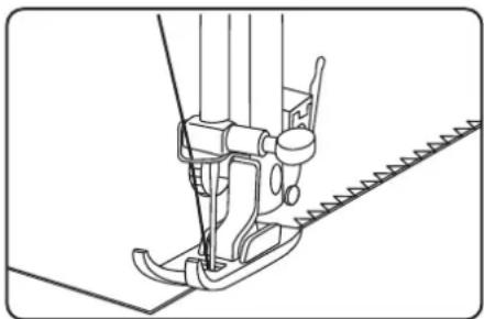
Technical line drawing of a sewing machine needle and chain (no text or symbols)10.11. Butt onholes

TIP
To determine the correct stitch length, we recommend sewing a test buttonhole on a scrap of fabric.
Presser foot: Buttonhole presser foot
Programme: Buttonhole programs
Stitch length: 0.5 to 1
▶ Set the foot and needle to their highest position.
▶ Replace the foot with the buttonhole presser foot.
Please read section "11.2. Removing and fitting the presser foot" on page 213 for more information.
Using a pencil or tailor's chalk, mark the place on the fabric where you want to sew the buttonhole and mark the required length of the buttonhole.
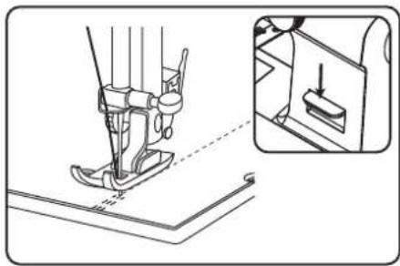
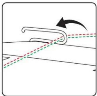
Line up the buttonhole presser foot with the slide at the rear end of the buttonhole.
natural_image
Technical line drawing of a mechanical assembly with two views (top and side), showing internal components and directional arrows (no text or symbols)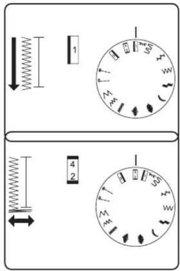
▶ Pass the upper thread through the opening on the buttonhole presser foot and pull both the upper thread and bobbin thread to the left-hand side.
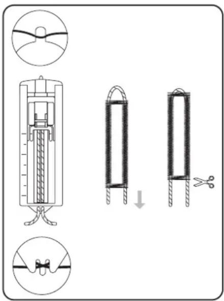
10.11.1. Procedure
▶ Select the program for the left bar on the program selection dial.
▶ Lower the foot and sew slowly until the bar is the required length.
- Raise the needle to its highest position and switch to the program for the bottom bar.
▶ Sew a few stitches of the bottom bar.
- Raise the needle to its highest position again and switch to the program for the right-hand bar.
Now sew the right-hand bar exactly the same length as the bar on the left-hand side.
- Raise the needle to its highest position and select the program for the top bar again.
natural_image
Line drawing of a mechanical spring-loaded tool with no text or symbolsThen sew a few stitches for the top bar as you did for the bottom bar.
Finally, we recommend setting the stitch length to "0" and sewing a few more stitches so that the threads are better linked and the buttonhole does not fray so quickly.
▶ Finally, separate the fabric between the seams with the enclosed cutter. Do this carefully to ensure you do not damage any of the bars.
TIP
We recommend putting a pin in front of the top bar to stop you cutting through it.
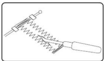
10.11.2. Reinforced butt onholes
We recommend reinforcing heavy-duty buttonholes with thread (crochet thread, reinforcement yarn or buttonhole yarn).
▶ Cut a piece of reinforcement yarn to fit the size of the buttonhole and place it around the buttonhole foot.
▶ Feed the yarn into the hook at the rear end of the presser foot and then bring the yarn forwards and fasten it on the front hook with a knot.
▶ Sew the buttonhole as usual. Ensure that the stitches catch the reinforcement yarn completely.
When the buttonhole program is finished, take the fabric out of the sewing machine and cut off the ends of the reinforcement yarn.

TIP
You should practise a few buttonholes on a piece of cloth first in order to learn how to use reinforcement yarn.
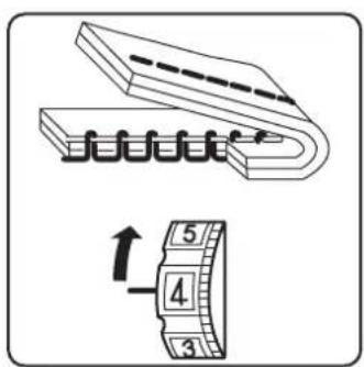
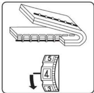
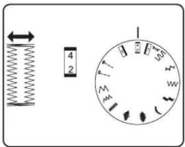
10.12. Gathering
Presser foot:....Standard foot Stitch length:....4
Reduce the upper thread tension (see Page 203) so that the bobbin thread is loose on the back of the fabric and is looped by the upper thread.
▶ Sew one or more rows of stitches. Do not cut the threads off right at the edge of the fabric but leave a length of about 10 centimetres on the ends.
▶ At the start of each row, knot the upper thread and bobbin thread.
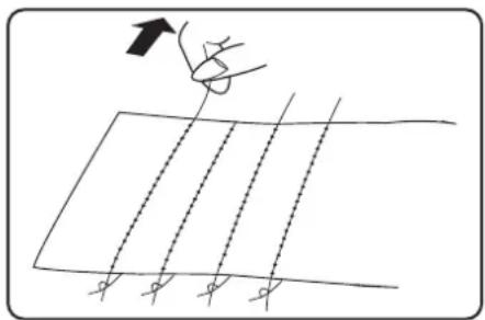
Hold on to the fabric on the side with the knots and, on the other side, pull one or more lower threads taut at the same time. Now push the fabric together on the bobbin thread. Once the fabric has been gathered to the desired width, knot the upper and lower threads of the second side.
▶ Make sure the gathering is even.
▶ Sew the gathers in place with one or more rows of straight stitches.

natural_image
Simple line drawing of a grid with diagonal lines and an arrow pointing upward (no text or symbols)10.13. Sewing with the free arm
The free arm enables you to sew tube-shaped pieces more easily. This function is very useful when sewing sleeves and trouser legs, for example.
You can easily turn your sewing machine into a free-arm machine by removing the extension table and accessories box (14) from the sewing machine.
The free arm is particularly useful for the following work:
- Repairing elbows and knees in garments.
- Sewing sleeves, especially in smaller garments
- Appliqué, embroidery or hemming edges, cuffs or trouser legs.
- Sewing elasticated waistbands on skirts or trousers.
10.14. Sewing with a twin needle
When buying new twin needles, make sure that the distance between the two needles does not exceed 4 mm.
The twin needle can be used to create beautiful two-colour patterns if you use different coloured threads for sewing.
Presser foot: Standard foot
Programme:.... A to L
Stitch length: 1 to 4

NOTICE!
Risk of damage!
Using the wrong sewing programme can cause the twin needle to bend or break.
■ Only use the twin needle in the programme specified here.

NOTICE!
Risk of damage!
When sewing a corner with the twin needle, it may bend or break.
■ Always lift the needle out of the fabric.
11. Maintenance, care and cleaning

CAUTION!
Risk of injury!
There is a risk of injury from accidental operation of the foot control pedal.
■ After finishing work or before maintenance work, always switch off the machine and unplug the mains plug from the socket.
11.1. Replacing the needle
▶ Turn the handwheel (8) towards you until the needle has reached its highest position.
▶ Loosen the needle clamp screw (22) by turning it (anti-clockwise) towards you.
Remove the needle from the needle holder.
Insert a new needle with the flat side facing backwards. Push the needle upwards until it can go no further.
▶ Tighten the needle clamp screw again (by turning clockwise).
natural_image
Diagram showing a screwdriver with directional arrows indicating motion (no text or symbols)i
Needles are available from specialist retailers.
Information on types and sizes can be found in section "12.1. Fabric, thread and needle table" on page 220.
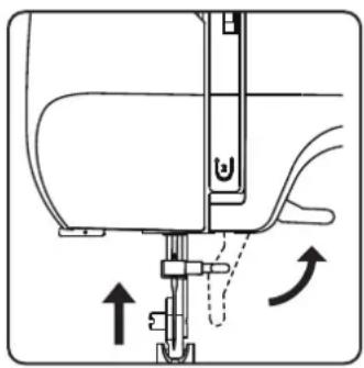
11.2. Removing and fi it ing the presser foot
11.2.1. Removal
▶ Turn the handwheel towards you until the needle has reached its highest position.
▶ Lift the presser foot (28) by raising the presser foot lever (23) to the highest position.
The presser foot will drop down if you push the presser foot release lever (24) behind the presser foot holder.
natural_image
Diagram of a sewing machine needle with directional arrows indicating movement (no text or symbols)
natural_image
Technical line drawing of a sewing machine needle and foot (no text or symbols)
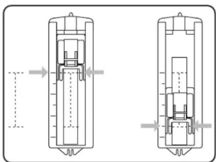
natural_image
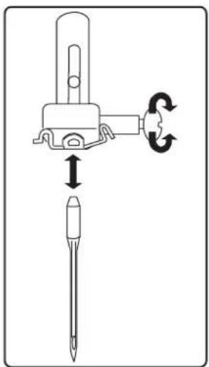
Diagram of a sewing machine needle and foot with a downward arrow indicating measurement or positioning (no text or symbols)11.2.2. Fitting
▶ Fit the presser foot so that the pin on the foot is directly under the groove of the presser foot holder.
▶ Lower the presser foot lever. The sewing foot will then click into place automatically.
▶ Raise the presser foot lever again.
11.3. Removing and fitting the presser foot holder
The presser foot holder does not need to be removed unless you want to make space to clean the fabric feeder (27).
11.3.1. Removal
▶ Move the needle to its highest position by turning the handwheel towards you and move the presser foot lever upwards.
Remove the foot from the presser foot holder and loosen the presser foot holder screw with the enclosed screwdriver.
11.3.2. Fitting
▶ Move the needle to its highest position by turning the handwheel towards you and move the presser foot lever upwards.
When you now insert the presser foot holder, push it up as far as possible and tighten the presser foot holder screw with the enclosed screw-driver.
11.4. Maintaining the sewing machine
The sewing machine is a sensitive mechanical product and requires regular maintenance to ensure it always functions perfectly.
You can carry out this maintenance yourself.
Maintenance primarily refers to: Cleaning and oiling.

Only use special sewing machine oils of the best quality for oiling, as other oils are not suitable.
Please note that there may be residues in the appliance after oiling. To remove these residues, sew a few stitches on a sample piece of fabric or a fabric remnant. This way you avoid soiling your fabric.
11.4.1. Cleaning the housing and foot control pedal
Before cleaning, pull the plug out of the mains socket.
Use a soft, dry cloth to clean the appliance and the foot control pedal. Avoid the use of chemical solutions and cleaning products because these may damage the appliance surface and/or the labels on it.
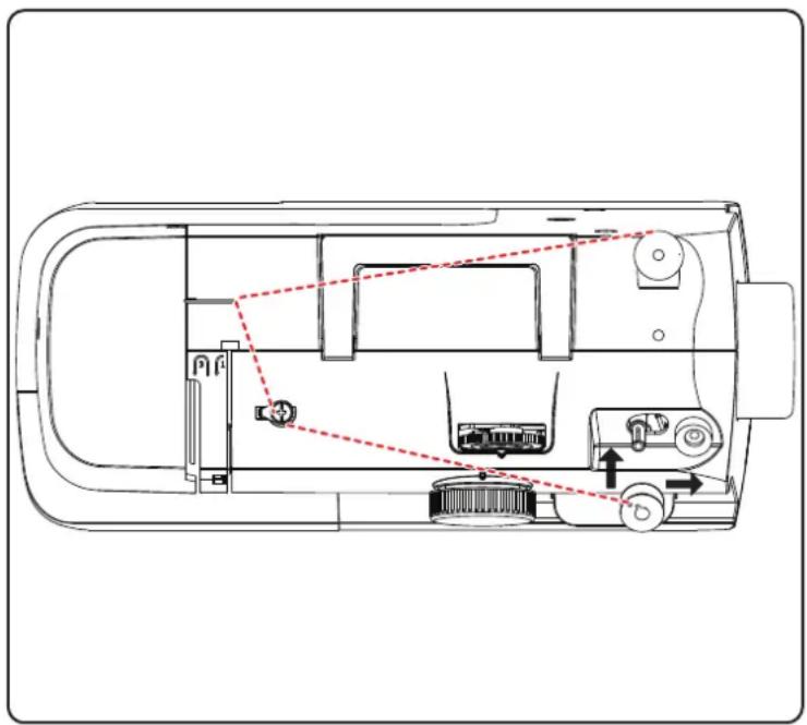
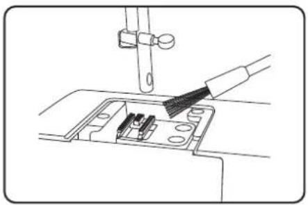
11.4.2. Cleaning the feeder
It is necessary to keep the fabric feeder teeth clean at all times to ensure perfect stitching.
Remove the needle and presser foot (see Page 213 onwards).
▶ Undo the screws on the needle plate to remove the needle plate from the machine.
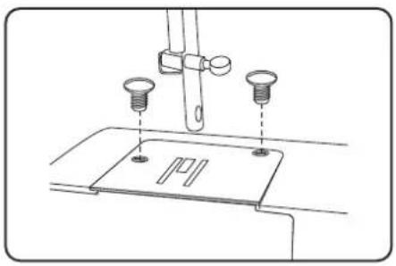
natural_image
Technical line drawing of a sewing machine needle with two screws and a base plate (no text or symbols)▶ Use the brush to remove dust and loose threads from the feeder teeth.
natural_image
Line drawing of a sewing machine needle being inserted into a socket (no text or symbols)▶ Refit the needle plate.
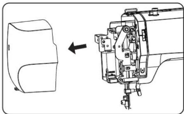
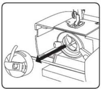
11.4.3. Cleaning and oiling the bobbin housing
▶ Move the needle to the highest position, otherwise the looper cannot be removed.
▶ Remove the bobbin case.
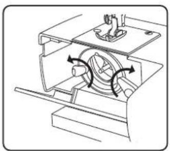
natural_image
Technical line drawing of a mechanical device with a rotating component and a directional arrow (no text or symbols)▶ Turn the snap levers outwards as shown
natural_image
Technical line drawing of a mechanical device with internal components and directional arrows indicating motion (no text or symbols)
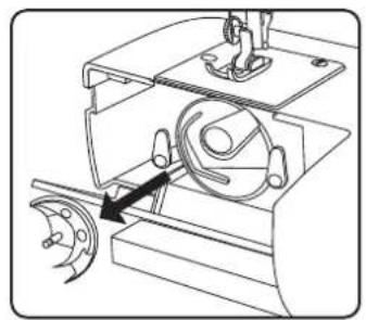
natural_image
Technical line drawing of a mechanical device with two circular components and a central hub (no text or symbols)Remove the shuttle track ring.
natural_image
Mechanical assembly diagram showing a motor and gear mechanism (no text or labels)Remove the looper by holding the pin in the centre of the looper.
natural_image
Technical line drawing of a mechanical assembly with no visible text or symbolsRemove all dirt particles from the shuttle track ring of the shuttle track and oil the parts with a cloth.
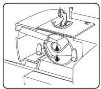
natural_image
Technical line drawing of a mechanical device with no visible text or symbols▶ Apply one or two drops of oil to the bobbin shuttle track as shown.
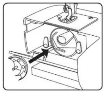
natural_image
Mechanical assembly diagram showing a rotating component with a highlighted arrow (no text or symbols)▶ Replace the looper by holding the pin in the centre of the looper.
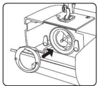
natural_image
Technical line drawing of a mechanical device with rotating components and a central dial (no text or symbols)▶ Replace the shuttle track ring.
▶ Turn the snap levers inwards as shown
▶ Finally, reinsert the bobbin case.

TIP
Depending on the frequency of use, this part of the machine is to be oiled more often.
11.5.Oilingthemachine

Your sewing machine is already oiled at the factory and ready for use.
11.5.1. Oil the needle mechanism behind the front flap
▶ Loosen the screws of the front flap.
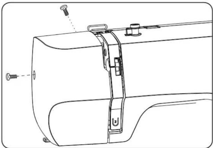
natural_image
Technical line drawing of a sewing machine component with screws and fastener (no text or symbols)Remove the front cover (20).

natural_image
Technical line drawing of a sewing machine with a side view showing internal components (no text or symbols)
natural_image
Technical line drawing of a mechanical assembly with no visible text or symbols
natural_image
Technical line drawing of a mechanical device with a rotating component and a handle (no text or symbols)Before oiling, the areas marked with arrows in the figure below should be cleaned.
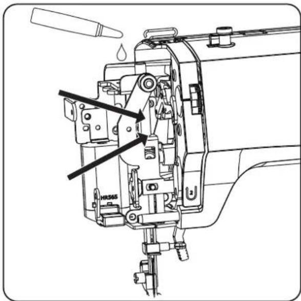
▶ After cleaning, re-oil the marked areas.
▶ Apply one or two drops of a good-quality sewing machine oil to these areas.
i
Don't forget to sew on a scrap of fabric first to soak up any oil that may escape.
12.Faults
If faults occur, please read this user manual to determine whether you have followed all instructions correctly.
Please only contact our customer services if none of the solutions provided are successful.
| Fault Cause Page | ||
| Machine does not run smoothly The machine must be oiled Page 215 | ||
| Dust and threads in shuttle track Page 215 on- wards. | ||
| Fabric remains on the teeth of the fabric feeder Page 215 | ||
| The wrong oil was used and clogged the machine Page 217 on- wards. | ||
| Upper thread breaks Upper thread | not threaded correctly Page 198 | |
| Thread tension is too high Page 203 | ||
| Needle is bent or blunt Page 205 | ||
| Thread thickness not right for the needle Page 220 | ||
| Needle not inserted correctly Page 213 | ||
| Fabric not pulled through from back at end of seam Page 206 | ||
| Needle plate, bobbin or presser foot is damaged | Contact customer services | |
| Bobbin thread breaks | Lower thread tangles because the thread is wound on to bobbin incorrectly | Page 196 |
| Lower thread is not under the tension spring in the bobbin case | Page 197 | |
| Needle breaks | Needle is inserted incorrectly Page 213 | |
| Needle is bent | Page 205 & 213 | |
| Needle is too fine | Page 220 | |
| Fabric pulled while sewing | Page 205 | |
| Knot in the thread | Page 198 | |
| Upper thread is threaded incorrectly Page 198 | ||
| Machine misses stitches | Needle is inserted incorrectly Page 213 | |
| Upper thread is threaded incorrectly Page 198 | ||
| Needle and/or thread not suitable for fabric | Page 220 | |
| Fabric too heavy or rigid | Page 220 | |
| Fabric pulled while sewing | Page 205 | |
| Puckering or gathering of seam | Upper thread tension too high | Page 203 |
| Machine threaded incorrectly | Page 198 onwards. | |
| Needle too large for the fabric | Page 220 | |
| Thread makes loops | Thread tension not adjusted | Page 203 |
| Upper thread not threaded correctly and/or bobbin thread not wound on to bobbin correctly | Page 196, 12 | |
| Thread thickness not suitable for the fabric | Page 220 | |
| Fabric feed irregular The stitch length | th is set to “0” Page 207 | |
| Thread ends are in the shuttle track Page 215 | ||
| Machine does not run Sewing machine | chine not connected correctly or there is no power from the socket | Page 195 |
| Thread ends in shuttle track Page 215 | ||
12.1. Fabric, thread and needle table
As a general rule, fine threads and needles are used to sew thin fabrics, thicker threads and needles are used for heavier fabrics. Always test the thread and needle thickness on a scrap of the fabric you intend to use. Use the same thread for needle and bobbin. If you sew stretch stitches on fine fabrics or synthetics, use a needle with a blue shaft (available from specialist retailers). These prevent stitches from being missed.
| Fabric type Thread Needle | |||
| Very lightweight fabrics | Chiffon, georgette, fine lace, organza, net, tulle 50 | Synthetics, silk | 65 |
| Lightweight fabrics | Batiste, voile, nylon, satin, lightweight linen 80 | Cotton | 65 |
| Silk, crêpe de Chine, sheer crêpe | 50Silk, synthetics | ||
| Jersey, swimwear, stockinette | 60Synthetics | ||
| Suede | 80Cotton | 75(Leather needle or jeans needle) | |
| Medium fabrics | Flannel, velours, velvet, muslin, poplin, linen, wool, felt, towelling, gaberdine | 60–80Cotton, silk | 75–90 |
| Knitted fabrics, stretch fabrics, jersey | 60Synthetics | 90 | |
| Leather, vinyl, suede | 80Cotton | 90(Leather needle or jeans needle) | |
| Heavy fabrics | Denim, coating | 50Cotton | 100 |
| Jersey | 50Synthetics | ||
| Wool, tweed | 50Silk | ||
| Very heavy fabrics | Canvas, sailcloth, upholstery fabrics | 80–100Cotton | 100 |
12.2. Useful sewing tips
12.2.1. Sewing thin and lightweight fabrics
Lightweight and thin fabrics can ride up in the machine as these materials are not always fed through the machine evenly.
When sewing these kinds of fabrics, lay some embroidery backing (available from specialist shops) or a piece of tissue paper under the material. This prevents irregular feeding.
12.2.2. Sewing elasticated fabrics
It can be easier to work with elastic materials if you sew the pieces of material together first with basting cotton or tacking yarn and then sew them together with small stitches without stretching the material.
Good results can also be obtained if you use special threads for sewing knitwear and stretch stitches.
13. Technicalspecifi cations
| Sewing machine | |
| Rated voltage: 220–240 V ~ 50 Hz | |
| Rated power: 71 W | |
| Motor: 70 W | |
| Light: | 1 W (LED, not replaceable) |
| Dimensions (W × D × H): | 345 × 145 × 270 mm |
| Weight: | Approx. 5 kg |
| Foot control | |
| Type: | HKT72C |
| Rated voltage: 200–240 V ~ 50 Hz – 0.5 A | |
| Protection class: | II |
 www.tux.comID 1111284182 www.tux.comID 1111284182 | |
14.Disposal

PACKAGING
Your appliance has been packaged to protect it from damage in transit. The packaging is made of materials that can be recycled in an environmentally friendly manner.
APPLIANCE
All old appliances marked with the symbol shown must not be disposed of in normal household waste.
In accordance with Directive 2012/19/EU, the appliance must be properly disposed of at the end of its service life.
This involves separating the materials in the appliance for the purpose of recycling as well as minimising the environmental impact and negative effects on human health.
Take old appliances to an electrical scrap collection point or a recycling centre.
Contact your local waste disposal company or your local authority for more information on this subject.
15. Service information
Please contact our Customer Service team if your device ever stops working the way you want or expect it to. There are several ways for you to contact us:
- In our Service-Community, you can meet other users, as well as our staff, and you can exchange your experiences and pass on your knowledge there.
You will find our Service-Community at community.medion.com.
• Alternatively, use our contact form at www.medion.com/contact.
- You can also contact our Service team via our hotline or by post.
Opening times Hotline number UK
| Mon – Fri: 08.00 – 20.00Sat – Sun: 10.00 – 16.00 | 1 | 0333 3213106 |
Service address
MEDION Electronics Ltd. 120 Faraday Park, Faraday Road, Dorcan Swindon SN3 5JF, Wiltshire United Kingdom

You can download this and many other sets of operating instructions from our service portal at www.medionservice.com.
We have stopped providing printed copies of our warranty terms and conditions as part of our commitment to sustainability, but you can access the warranty terms and conditions on our service portal.
You can also scan the QR code on the side of the screen, to download the operating instructions onto your mobile device from the service portal.
16. LegalNotice
Copyright 2024
Date: 28. May 2024
All rights reserved.
These operating instructions are protected by copyright.
Mechanical, electronic and any other forms of reproduction are prohibited without the written permission of the manufacturer.
Copyright is owned by the company:
MEDION AG
Am Zehnthof 77
45307 Essen
Germany
Please note that you cannot use the address above for returns. Please always contact our Customer Service team first.

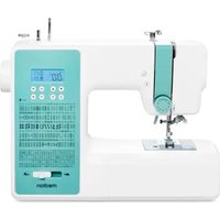
- Inhaltsverzeichnis
- Einstellungen
- Knopfl öcher
- TIPP
- Kräuseln
- Einsetzen
- i
- Coupe du fi I
- Fronçage
- Mise en place du pied-de-biche
- Draadspanningen controleren
- Juiste naad
- Onzuivere naden
- Rimpelen
- Plaatsen
- Trabajos previos
- Subida del hilo inferior
- Costuras irregulares
- Costura inversa
- Selector de programas
- ¡AVISO!
- ¡Peligro de daños!
- Ojales
- CONSEJO
- Fruncido
- Colocación
- Taglio del fi lo
- Punto elastico
- Asole
- CONSIGLIO
- Increspature
- Inserimento
- About this user manual
- Explanation of symbols
- DANGER!
- WARNING!
- CAUTION!
- NOTICE!
- TIP
- Proper use
- Declaration of conformity
- Safety instructions
- Keep children away from electrical appliances
- Risk of choking and suffocation!
- Mains cable and power supply
- General information
- Never carry out repairs yourself
- Risk of electric shock!
- Handle the appliance with care
- Cleaning and storage
- Package contents
- Appliance overview
- not illustrated
- Electrical connections
- Risk of injury!
- Controlling the sewing speed
- Att aching and removing the extension table
- Preparatory work
- Fitting a spool
- Winding thread onto the bobbin
- Removing the bobbin case
- Threading the bobbin case
- Inserting the bobbin case
- Threading the upper thread
- Illustration of the upper thread guide
- Threading the upper threads on twin needles
- Illustration of the upper thread guide
- Bringing up the bobbin thread
- Sett ings
- Sett ing the thread tension
- Adjusting the upper thread tension
- Adjusting the bobbin thread tension
- Checking the thread tension
- Correct stitching
- Incorrect stitching
- Solution:
- Sewing
- General information
- Selecting the right needle
- Risk of damage!
- Raising and lowering the presser foot
- Reverse stitching
- Removing fabric from the sewing machine
- Changing the sewing direction
- Cutting the thread
- The program selection dial
- Stitch length adjustment
- Straight stitch
- Zigzag stitch
- TIPS FOR ZIGZAG STITCHES
- Satin stitch
- Blind stitch
- Stretch stitch
- Sewing on elastic bands
- Overlock stitch
- Butt onholes
- Procedure
- Reinforced butt onholes
- Gathering
- Sewing with the free arm
- Sewing with a twin needle
- Maintenance, care and cleaning
- Replacing the needle
- Removing and fi it ing the presser foot
- Removal
- Fitting
- Removing and fitting the presser foot holder
- Removal
- Fitting
- Maintaining the sewing machine
- Cleaning the housing and foot control pedal
- Cleaning the feeder
- Cleaning and oiling the bobbin housing
- 11.5.Oilingthemachine
- Oil the needle mechanism behind the front flap
- 12.Faults
- Fabric, thread and needle table
- Useful sewing tips
- Sewing thin and lightweight fabrics
- Sewing elasticated fabrics
- Technicalspecifi cations
- 14.Disposal
- PACKAGING
- APPLIANCE
- Service information
- Service address
- LegalNotice
Brand : MEDION
Model : LIFE SM70
Category : Sewing machine