MS 713 - Sander Flex - Free user manual and instructions
Find the device manual for free MS 713 Flex in PDF.


| Product type | Orbital finishing sander |
| Brand | Flex |
| Model | MS 713 |
| Weight | 1.3 kg |
| Power supply | 230 V ~ 50/60 Hz |
| Current consumption | 220 W |
| Motor power | 120 W |
| Max speed (no load) | 13,000 strokes/min |
| Sound pressure level LpA | 84 dB(A) |
| Sound power level LWA | 97 dB(A) |
| Typical weighted acceleration | 5 m/s² |
| Protection class | II (double insulation) |
| Sanding sheet type | Hook-and-loop (102 × 115 mm) or traditional (115 × 140 mm) |
| Dust extraction system | Integrated dust container, possible to connect a vacuum cleaner |
| Punch | Integrated for punching dust holes in sheets |
| Intended use | Dry sanding of wood, plaster, metal, plastic surfaces; professional and craft work |
| Cleaning | Blow with dry compressed air; do not use solvent |
| Periodic maintenance | Complete overhaul after approx. 200 h of use (brush replacement, lubrication) |
| Spare parts | Use exclusively original FLEX parts |
| Repairability | Entrust repairs to a FLEX authorized workshop |
| Disposal | Do not dispose of with household waste; recycling according to WEEE directive |
| Certifications | CE, compliant with EN 60745, directives 2014/30/EU, 2006/42/EC, 2011/65/EU |
Frequently Asked Questions - MS 713 Flex
User questions about MS 713 Flex
0 question about this device. Answer the ones you know or ask your own.
Ask a new question about this device
Download the instructions for your Sander in PDF format for free! Find your manual MS 713 - Flex and take your electronic device back in hand. On this page are published all the documents necessary for the use of your device. MS 713 by Flex.
USER MANUAL MS 713 Flex
natural_image
Illustration of a power tool with a handle and base plate (no text or symbols)natural_image
Close-up of a mechanical component with a circular dial and arrow indicator (no readable text or symbols)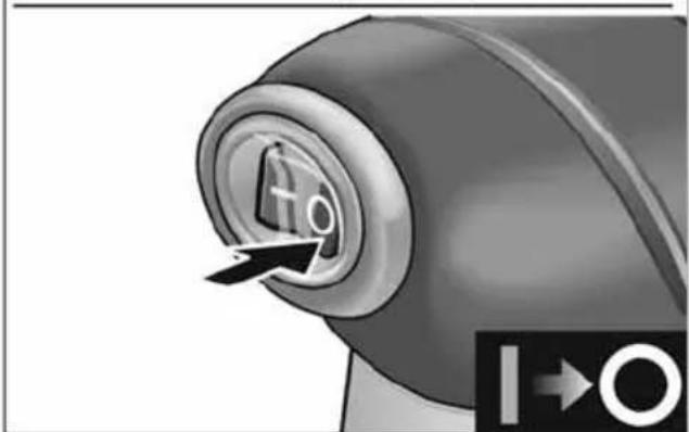
natural_image
Close-up of a mechanical component with a circular dial and directional arrow, no visible text or symbolsnatural_image
Two technical diagrams showing a mechanical assembly with mounting flanges and a base plate, no text or symbols present.natural_image
Mechanical component diagram showing a base with labeled parts A and B, no readable text or symbols present.natural_image
3D rendering of a gray rectangular electronic component with multiple pins and mounting holes (no text or symbols)natural_image
Mechanical assembly diagram showing a CNC machine with rotating base and mounting base (no text or symbols)natural_image
Illustration of two metal plates with bolts, one open and one closed, showing different mounting points (no text or symbols)Staubabsaugung

WARNUNG!
natural_image
Illustration of a hand using a power tool to adjust or install a component, showing no text or symbols.natural_image
Illustration of a hand pouring granular material from a container (no text or symbols)
HINWEIS
natural_image
Two-step illustration of a power tool being adjusted for installation, showing the blade and cable assembly (no text or symbols)Arbeitshinweise
natural_image
Hand using a power tool on a wooden surface, no text or symbols visibleSchleifvorgang
Eckhard Rühle Manager Research & Development (R & D)
Klaus Peter Weinper Head of Quality Department (QD)
10.08.2018
Symbols used in this manual ..... 12
Symbols on the appliance ..... 12
For your safety 12
Noise and vibration 13
Technical specifications 14
Overview 15
Instructions for use 16
Maintenance and care 19
Disposal information 19
C ∈ Declaration of Conformity ..... 20
UK CA Declaration of Conformity ..... 20
Exemption from liability 20
Symbols used in this manual

WARNING!
Denotes impending danger. Non-observance of this warning may result in death or extremely severe injuries.

CAUTION!
Denotes a possibly dangerous situation. Non-observance of this warning may result in slight injury or damage to property.

NOTE
Denotes application tips and important information.
Symbols on the appliance

Before switching on the power tool, read the operating manual!
Wear goggles!


Disposal information for the old machine (see page 19)!
For your safety

WARNING!
Before using the power tool, please read and follow:
– these operating instructions,
- the "General safety instructions" for handling electric power tools in the enclosed booklet (document no.: (315.915),
– the currently valid site rules and the regulations for the prevention of accidents. This power tool is state of the art and has been constructed in accordance with the acknowledged safety regulations.
Nevertheless, when in use, the power tool may be a danger to life and limb of the user or a third party, or the power tool or other property may be damaged. The power tool may be operated only if it is
- as intended,
– in perfect working order.
Faults which impair safety must be repaired immediately.
Intended use
The orbital sander is designed
– for commercial use in industry and trade,
– for use with suitable tools recommended by the manufacturer for this power tool.
The FLEX orbital sander can be used with Velcro-backed sandpaper (102 mm x 115 mm) or normal sheets of sandpaper (115 mm x 140 mm). This sander is suitable for coarse, medium or fine sanding of wood, plaster, metal an plastics. It is ideal for leveling wallboard joints, finishing cabinets, fitting screens and soors an for general finishing work in the shop.
This orbital sander is also the ideal tool for sanding flat the joints between gypsum plasterboard as well as for fine sanding cabinets, precision installation of mosquito net windows and doors and general sanding work in the workshop
Safety instructions for orbital sander

WARNING!
Read all safety warnings and all instructions. Failure to follow the warnings and instructions may result in electric shock, fire and/or serious injuries. Save all warnings and instructions for future reference.
■ Always disconnect the sander cord plug from the power circuit before changing abrasive sheets!
■ Use dust mask! Wear a protective mask to minimize breathing in the fine dust created while sanding.
■ Never run sander with dust container or dust collector assembly removed! Otherwise, very fine dust particles could be blown into the eyes.
■ Use proper safety equipment!
Wear safety goggles to protect your eyes.
■ Sanding of lead-based paint is not recommended.
Lead paint should be removed by a specialist only.
■ Use of this tool can generate and disburse dust or other airborne particles, including wood dust, crystalline silica dust and asbestos dust. Direct particles away from face and body.
Always operate tool in well ventilated area and provide for proper dust removal. Use dust collection system wherever possible. Exposure to the dust may cause serious and permanent respiratory or other injury, including silicosis (a serious lung disease), cancer, and death. Avoid breathing the dust, and avoid prolonged contact with dust. Allowing dust to get into your mouth or eyes, or lay on your skin may promote absorption of harmful material. Always use properly fitting NIOSH/OSHA approved respiratory protection appropriate for the dust exposure, and wash exposed areas with soap and water.
Additional safety instructions
The mains voltage and the voltage specifications on the rating plate must correspond.
Noise and vibration

NOTE
Values for the A-weighted sound pressure level and for the total vibration values can be found in the “Technical specifications” table. The noise and vibration values have been determined in accordance with EN 60745.

CAUTION!
The indicated measurements refer to new power tools. Daily use causes the noise and vibration values to change.

NOTE
The vibration emission level given in this information sheet has been measured in accordance with a standardised test given in EN 60745 and may be used to compare one tool with another. It may be used for a preliminary assessment of exposure. The declared vibration emission level represents the main applications of the tool. However if the tool is used for different applications, with different accessories or poorly maintained, the vibration emission may differ. This may significantly increase the exposure level over the total working period. However if the tool is used for different applications, with different accessories or poorly maintained, the vibration emission may differ.
This may significantly decrease the exposure level over the total working period.
Identify additional safety measures to protect the operator from the effects of vibration such as: maintain the tool and the accessories, keep the hands warm, organisation of work patterns.

CAUTION!
Wear ear protection at a sound pressure above 85 dB(A).
Technical specifications
| MS713 | ||
| Machine type Orbital sander | ||
| Mains voltage V 230 | ||
| Rated speed (no load) opm. 13,000 | ||
| Power consumption W 220 | ||
| Power output W 120 | ||
| Weight kg 1.3 | ||
| Typical mean effective Acceleration | m/s^2 | 5 |
| Sound pressure L_pA | dB(A) 84 | |
| Sound power level L_WA | dB(A) 97 | |
| Wear ear protection! | ||
| Protection class | II / ☐ | |
Overview
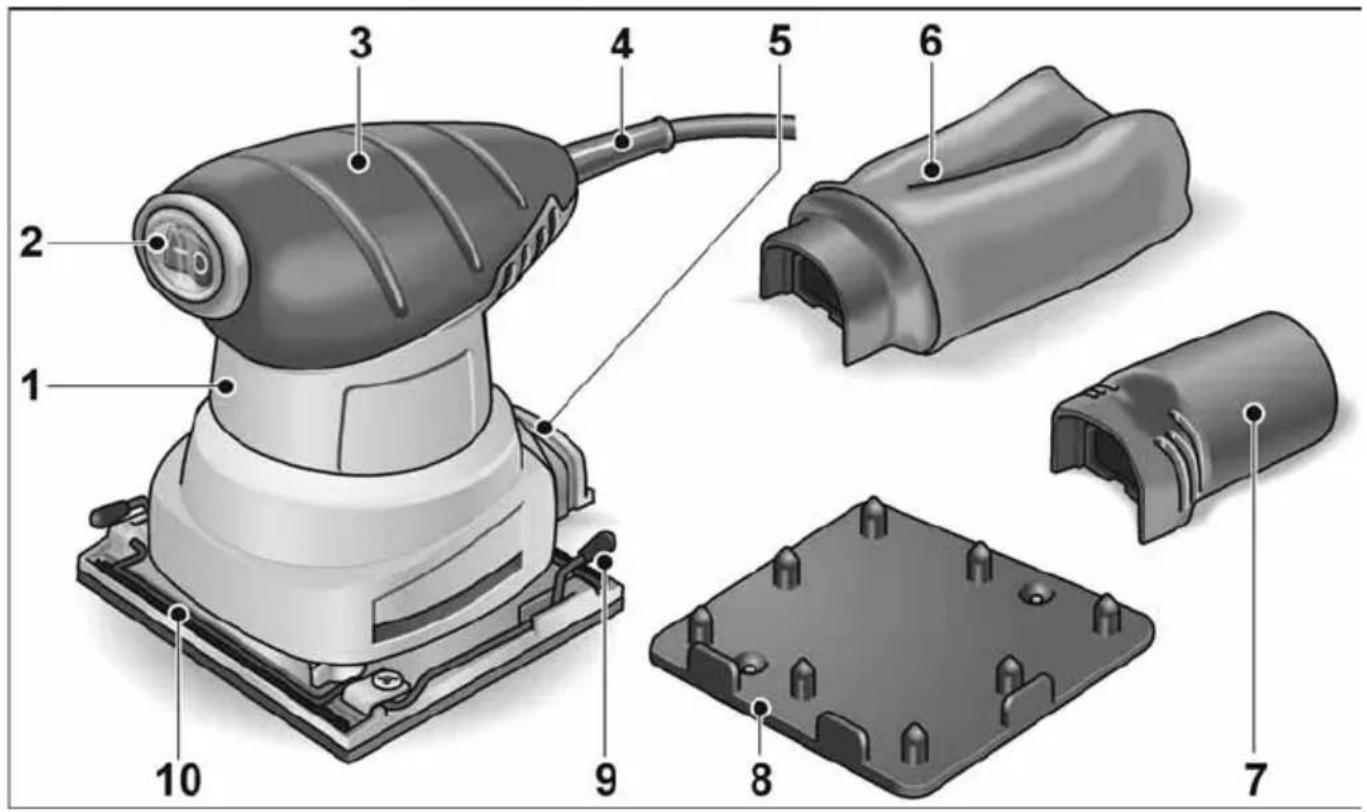
3 Housing
4 Switch
Switches the power tool on and off.
5 Handle
6 Power cord
7 Connection for extractor
8 Dust bag
9 Hose adapter
10 Sandpaper hole punch
11 Clamping lever
12 Clamping bracket
Instructions for use

WARNING!
Before performing any work on the electric power tool, pull out the mains plug.
Before switching on the power tool
Unpack power tool and accessories and check that no parts are missing or damaged.
Switching on and off

CAUTION!
Make certain the switch is in the "O" position, and the power source is the same as that specified on the tool's nameplate.
- Connect the tool to the power source.
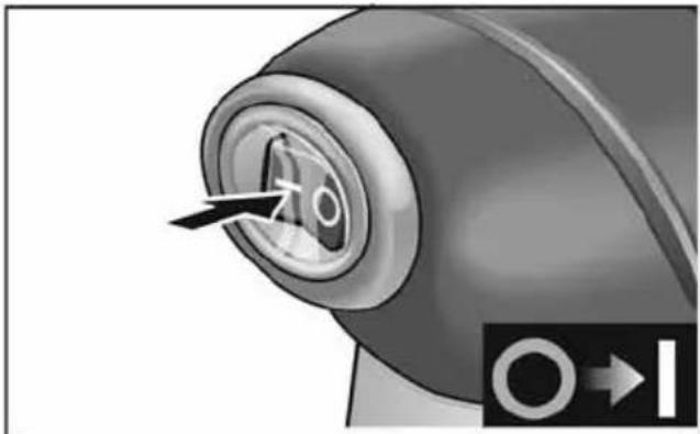
- The switch button is labeled "I" and "O". Depress the "I" end of the switch button to start motor. Depress the "O" end of the switch button to stop motor.
natural_image
Close-up of a mechanical component with a circular dial and arrow, showing no visible text or symbols.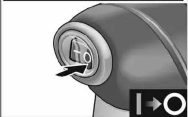
natural_image
Close-up of a mechanical component with a circular dial and directional arrow, no visible text or symbolsAttaching hook & loop abrasive

WARNING!
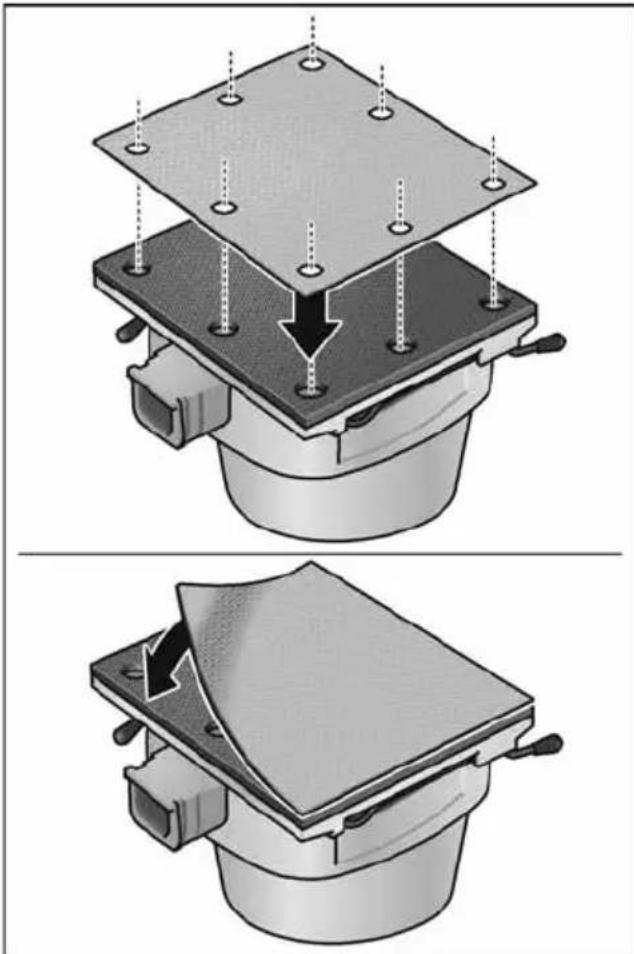
Before performing any work on the electric power tool, pull out the mains plug! To install hook & loop abrasives, align the abrasive with the sander pad and press in place.
natural_image
Two technical diagrams showing a mechanical assembly with arrows indicating force or movement, no text or symbols present.Attaching conventional abrasive

WARNING!
Before performing any work on the electric power tool, pull out the mains plug!
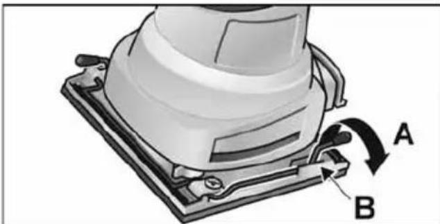
- Open paper clamp by lifting up on lever (A) to release it from the locking tab (B).
natural_image
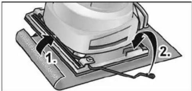
Mechanical component diagram showing a base with labeled parts A and B, no readable text or symbols present.- Position one (115 mm) wide end, of a 115 mm x 140 mm piece of sandpaper, under the open paper clamp (1.), and hold, while lifting paper clamp lever up and placing it behind the locking tab to secure the paper in place (2.).
-
Open second paper clamp (as described in Step 1).
-
Stretch the sandpaper tight over the pad (1.), position the loose end under the second paper clamp, and close paper clamp (2.).
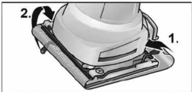
- Punch holes in paper (for dust extraction), as instructed in „Paper punch“ section of this manual.
Paper punch
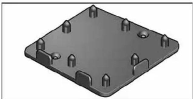
A Paper Punch is provided with the Model MS713 Sander.
natural_image
3D rendering of a gray rectangular electronic component with multiple pins and mounting holes (no text or symbols)The punch is used to make eight holes through the abrasive. These holes allow the sanding dust to be extracted directly through the pad. The punch can be mounted to a workbench or wall using 2 flat head screws. Use the punch as follows:

WARNING!
Before performing any work on the electric power tool, pull out the mains plug!
- Install the abrasive to the sandar as described in the „Attaching hook & loop abrasive“ section, or the „Attaching conventional abrasive“ section of this manual.
- Position the sander to the punch, aligning the sander pad with the two corner guides on the punch. Push sander onto the punch until seated.
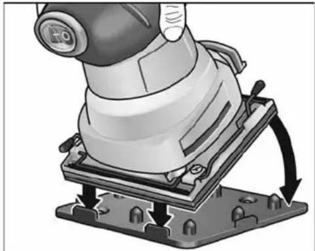
natural_image
Illustration of a robotic arm operating on a base platform with arrows indicating motion (no text or symbols)- Remove sander from punch.
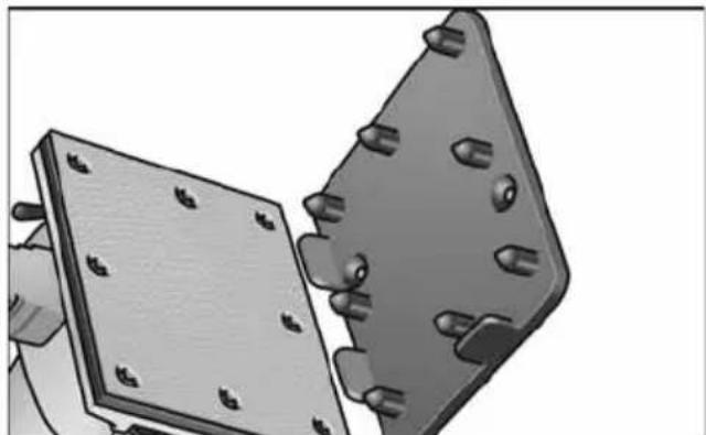
natural_image
Illustration of two metal plates with bolt holes, one open and one tilted (no text or symbols)Dust extraction

WARNING!
Before performing any work on the electric power tool, pull out the mains plug!
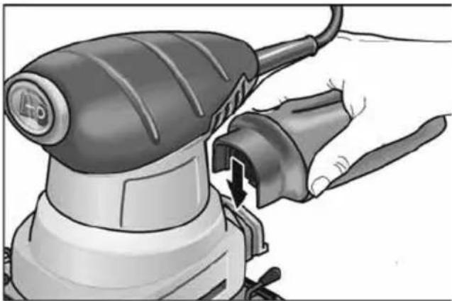
- Attach the dust bag to the connection of the sander.
natural_image
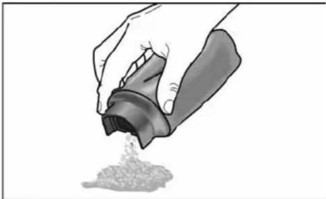
Illustration of a hand using a power tool to adjust or install a component, showing a curved arrow indicating rotation (no text or symbols present)- Periodically remove dust container from flange and empty collected dust.
natural_image
Illustration of a hand pouring granular material from a container (no text or symbols)
NOTE
A light twist facilitates removal and attachment of the dust bag.
Tap container lightly to remove compacted dust. Do not wash container. Dry compressed air may be used to blow out container.

CAUTION!
Wear safety glasses while using compressed air.

CAUTION!
Never run sander with dust container or dust collector assembly removed. Otherwise, very fine dust particles could be blown into the eyes.
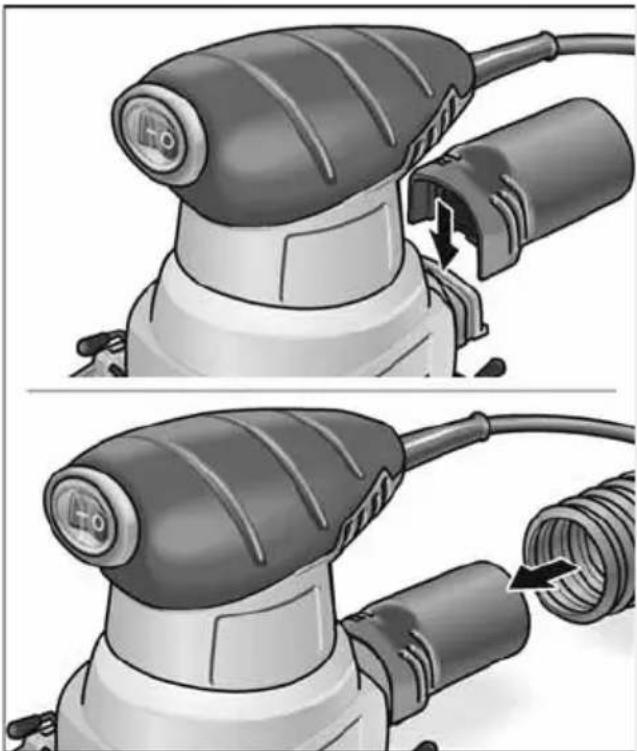
It is possible to connect a dust extraction unit using the hose adapter provided.
natural_image
Two-step illustration of a power tool being adjusted for installation, showing the blade and cable assembly (no text or symbols)Operating instructions
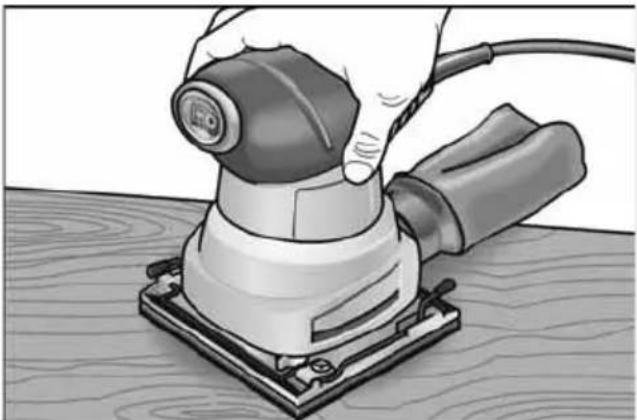
How to hold sander
Model MS713 is designed to be hold as shown.
natural_image
Hand using a power tool on a wooden surface, no text or symbols visibleSanding procedure
The normal weight of the machine is sufficient for efficient sanding. Do not put additional pressure on the machine. This would only slow down the speed of the pad, reducing the sanding efficiency and put an additional burden on the motor. In addition, it might cause the sander to jump on the work. Let the sander do the work.
Maintenance and care

WARNING!
Before performing any work on the electric power tool, pull out the mains plug.
Keep tool clean!
■ Periodically blow out all air passages with dry, compressed air.
■ Remove buildup of grime resulting from working with green or sappy wood.
■ All plastic parts should be cleaned with a soft damp cloth.
■ NEVER use solvents to clean plastic parts.

CAUTION!
Wear safety glasses while using compressed air.
Failure to Sart
Should your tool fail to start, check to make sure the prongs on the cord plug are making good contact in the outlet. Also, check for blown fuses or open circuit breakers in the line.
Brush inspection and lubrication
At approximately 200 hours of use, take or send your tool to your nearest Authorized FLEX Power Tool Service Agent to be thoroughly cleaned and inspected. Worn parts replaced, when necessary. Relubricated with fresh lubricant, if required and reassembled with new brushes. Thereafter, the performance of the tool should be checked.
Any loss of power before the above maintenance check may indicate the need for immediate servicing of your tool. Do not continue to operate tool under this condition. If proper operating voltage is present, return your tool to an Authorized FLEX Power Tool Service Agent for immediate service.
Repairs
Repairs may be carried out by an authorised customer service centre only.
Spare parts and accessories

NOTE
Use only original parts supplied by the manufacturer for replacement purposes. If non-original parts are used, the guarantee obligations of the manufacturer will be deemed null and void.
For other accessories, in particular cutting accessories, please refer to the manufacturer's catalogues.
Exploded drawings and spare-part lists can be found on our homepage:
www.flex-tools.com
Disposal information

WARNING!
Render redundant power tools unusable by removing the power cord.

EU countries only Do not throw electric power tools into the household waste!
In accordance with the European Directive 2012/19/EC on Waste Electrical and Electronic Equipment and transposition into national law used electric power tools must be collected separately and recycled in an environmentally friendly manner.

Raw material recovery instead of waste disposal.
Device, accessories and packaging should be recycled in an environmentally friendly manner. Plastic parts are identified for recycling according to material type.

NOTE
Please ask your dealer about disposal options!
CE Declaration of Conformity
We declare under our sole responsibility that the product described under "Technical specifications" conforms to the following standards or normative documents:
EN 60745 in accordance with the regulations of the directives 2014/30/EU, 2006/42/EC, 2011/65/EU.
Responsible for technical documents: FLEX-Elektrowerkzeuge GmbH, R & D Bahnhofstrasse 15, D-71711 Steinheim/Murr
Eckhard Rühle Manager Research & Development (R & D)
Klaus Peter Weinper Head of Quality Department (QD)
Declaration of Conformity
We as the manufacturer: FLEX Elektrowerkzeuge GmbH,
Business address: Bahnhofstr. 15, 71711 Steinheim, Germany
declare under our sole responsibility, that the product(s) described under „Technical specifications“ fulfills all the relevant provisions of The Supply of Machinery (Safety) Regulations S.I. 2008/1597 and also fulfills all the relevant provisions of the following UK Regulations: Electromagnetic Compatibility Regulations S.I. 2016/1091, The Restriction of the Use of Certain Hazardous Substances in Electrical and Electronic Equipment Regulations S.I. 2012/3032 and are manufactured in accordance with the following designated Standards:
BS EN 62841-1:2015, BS EN 62841-2-4:2014, BS EN 55014-1:2017, BS EN 55014-2:2015, BS EN 61000-3-2:2014, BS EN 61000-3-3:2013
Place of declaration: Steinheim, Germany. Responsible person: Peter Lameli, Technical Director – FLEX-Elektrowerk- zeuge GmbH
Contact details for Great Britain: FLEX Power Tools Limited, Unit 8 Anglo Office Park, Lincoln Road, HP 12, 3RH Buckinghamshire, United Kingdom
Peter Lameli Technical Head
Klaus Peter Weinper Head of Quality Department (QD)
19.05.2021
Exemption from liability
The manufacturer and his representative are not liable for any damage and lost profit due to interruption in business caused by the product or by an unusable product.
The manufacturer and his representative are not liable for any damage which was caused by improper use of the power tool or by use of the power tool with products from other manufacturers.
Table des matières
1 C a r t e r
natural_image
Close-up of a mechanical component with a circular dial and arrow indicator (no readable text or symbols)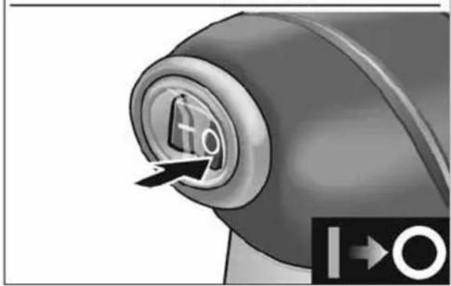
natural_image
Close-up of a mechanical component with a circular dial labeled 'H0' and an arrow pointing to it, showing no readable text or symbols.natural_image
Two technical diagrams showing a mechanical assembly with mounting flanges and a base plate, no text or symbols present.natural_image
Mechanical component diagram showing a base with labeled parts A and B, no readable text or symbols present.natural_image
3D rendering of a gray rectangular electronic component with multiple pins and mounting holes (no text or symbols)natural_image
Mechanical device with a rotating base and mounting base, showing mechanical components and motion arrows (no text or symbols)natural_image
Illustration of two metal plates with bolt holes, one tilted and one partially inserted (no text or symbols)natural_image
Illustration of a hand using a power tool to adjust or install a component, showing no text or symbols.natural_image
Illustration of a hand pouring granular substance from a container (no text or symbols)
REMARQUE
natural_image
Two-panel illustration showing a power tool being cut with a cable, no text or symbols presentnatural_image
Hand using a power tool on a wooden surface, no text or symbols visibleEckhard Rühle Manager Research & Development (R & D)
Klaus Peter Weinper Head of Quality Department (QD)
10.08.2018
natural_image
Close-up of a mechanical component with a circular dial and arrow indicator (no readable text or symbols)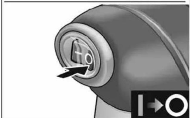
natural_image
Close-up of a mechanical component with a circular dial labeled 'H0' and an arrow pointing to it, showing no readable text or symbols.natural_image
Two-step diagram showing a mechanical assembly with a flat plate and directional arrows indicating motion (no text or symbols)natural_image
Mechanical component diagram showing a base with labeled parts A and B, no readable text or symbols present.natural_image
3D rendering of a gray plastic component with multiple bolt holes and mounting brackets (no text or symbols)natural_image
Mechanical assembly diagram showing a lathe machining a workpiece with arrows indicating motion (no text or symbols present)natural_image
Illustration of two metal plates with bolt holes, one tilted and one tilted with rivets (no text or symbols)natural_image
Illustration of a hand using a power tool to adjust or install a component, showing no text or symbols present.natural_image
Illustration of hands pouring granular material from a container (no text or symbols)i AVVISO
natural_image
Two-step illustration of a power tool being adjusted for installation, showing the blade and cable assembly (no text or symbols)natural_image
Hand using a power tool on a wooden surface, no text or symbols visibleKlaus Peter Weinper Head of Quality Department (QD)
10.08.2018
natural_image
Close-up of a mechanical component with a pointed tip and arrow, showing no visible text or symbols.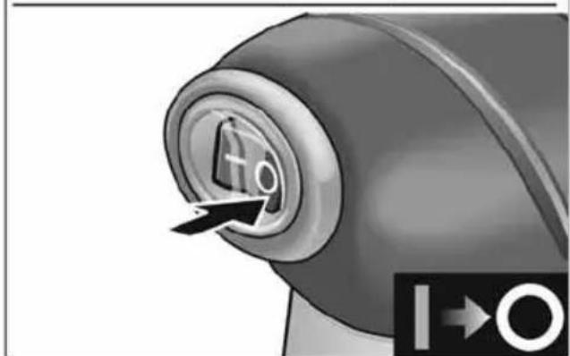
natural_image
Close-up of a mechanical knob with a circular dial labeled 'H0' and an arrow pointing to it, next to a black symbol (no readable text or symbols)natural_image
Two technical diagrams showing a mechanical assembly with mounting flanges and a base plate, no text or symbols present.natural_image
Mechanical component diagram showing a base with labeled parts A and B, no readable text or symbols present.natural_image
3D rendering of a gray rectangular electronic component with multiple pins and mounting holes (no text or symbols)natural_image
Illustration of a robotic arm operating on a base platform with arrows indicating motion (no text or symbols)natural_image
Illustration of two metal plates with bolt holes, one tilted and one tilted (no text or symbols)Aspiración de polvo

¡ADVERTENCIA!
natural_image
Illustration of a hand using a power tool to adjust or install a component, showing a curved arrow indicating rotation (no text or symbols present)natural_image
Illustration of a hand pouring granular material from a container (no text or symbols)
NOTA
natural_image
Two-step illustration of a power tool being adjusted for installation, showing the blade and cable assembly (no text or symbols)natural_image
Hand using a power tool on a workbench, no visible text or symbolsEckhard Rühle
Manager Research & Development (R & D)
Klaus Peter Weinper
Head of Quality Department (QD)
10.08.2018
natural_image
Close-up of a mechanical component with a circular dial and arrow indicator (no readable text or symbols)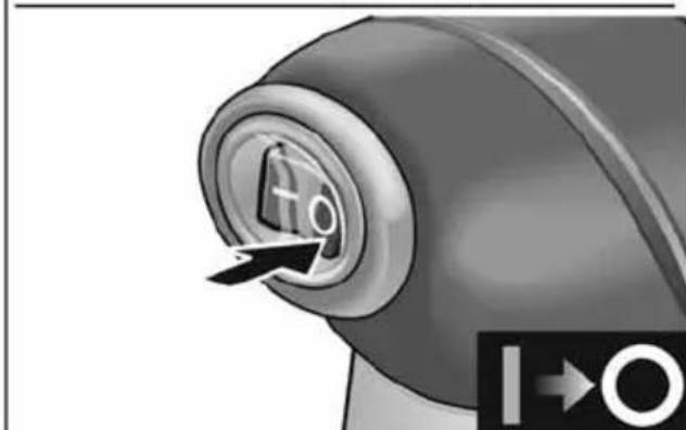
natural_image
Close-up of a mechanical component with a circular dial and directional arrow, no visible text or symbolsnatural_image
Two-step diagram showing a mechanical assembly with a base plate and mounting bracket, no text or symbols present.natural_image
Mechanical component diagram showing a base with labeled parts A and B, no readable text or symbols present.natural_image
3D rendering of a gray rectangular electronic component with multiple pins and mounting holes (no text or symbols)natural_image
Mechanical assembly diagram showing a turning tool on a base with arrows indicating motion (no text or symbols)natural_image
Illustration of two metal plates with bolt holes, one tilted and one partially filled (no text or symbols)Stofafzuiging

WAARSCHUWING!
natural_image
Illustration of a hand using a power tool to adjust or install a component, showing no text or symbols present.natural_image
Illustration of a hand pouring granular material from a container (no text or symbols)
LET OP
natural_image
Two-step illustration of a power tool being adjusted for installation, showing blade and cable details (no text or symbols)natural_image
Hand using a power tool on a wooden surface, no text or symbols visibleSchuurprocedure
Eckhard Rühle
Manager Research & Development (R & D)
Klaus Peter Weinper
Head of Quality
Department (QD)
10.08.2018
natural_image
Two technical diagrams showing a mechanical assembly with arrows indicating force or movement, no text or symbols present.natural_image
Mechanical component diagram showing a base with labeled parts A and B, no readable text or symbols present.natural_image
3D rendering of a gray plastic component with multiple bolt holes and mounting brackets (no text or symbols)natural_image
Illustration of a robotic arm operating on a base platform with directional arrows indicating movement (no text or symbols)natural_image
Illustration of two metal plates with bolt holes, one tilted and one partially filled (no text or symbols)Dammutsug
WARNING!
natural_image
Illustration of a hand using a power tool to adjust or install a component, showing no text or symbols.natural_image
Illustration of a hand pouring granular material from a container (no text or symbols)i OBS
natural_image
Illustration of a power tool with a circular head and handle, showing mechanical components (no text or symbols)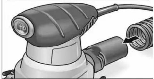
natural_image
Illustration of a power tool with a coiled cable and head screw (no text or symbols)Arbetsanvisningar
natural_image
Hand using a power tool on a wooden surface, no text or symbols visibleSlipningsförfarande
Eckhard Rühle
Manager Research &
Development (R & D)
Klaus Peter Weinper
Head of Quality
Department (QD)
10.08.2018



- Staubabsaugung
- WARNUNG!
- HINWEIS
- Arbeitshinweise
- Schleifvorgang
- Symbols used in this manual
- WARNING!
- CAUTION!
- NOTE
- Symbols on the appliance
- For your safety
- Intended use
- Safety instructions for orbital sander
- Additional safety instructions
- Noise and vibration
- Overview
- Instructions for use
- Before switching on the power tool
- Switching on and off
- Attaching hook & loop abrasive
- Attaching conventional abrasive
- Paper punch
- Dust extraction
- Operating instructions
- Sanding procedure
- Maintenance and care
- Keep tool clean!
- Failure to Sart
- Brush inspection and lubrication
- Repairs
- Spare parts and accessories
- Disposal information
- CE Declaration of Conformity
- Declaration of Conformity
- Exemption from liability
- Table des matières
- REMARQUE
- i AVVISO
- Aspiración de polvo
- ¡ADVERTENCIA!
- NOTA
- Stofafzuiging
- WAARSCHUWING!
- LET OP
- Schuurprocedure
- Dammutsug
- i OBS
- Arbetsanvisningar
- Slipningsförfarande
Brand : Flex
Model : MS 713
Category : Sander