S2 IP - Lighting Cameo - Free user manual and instructions
Find the device manual for free S2 IP Cameo in PDF.


User questions about S2 IP Cameo
0 question about this device. Answer the ones you know or ask your own.
Ask a new question about this device
Download the instructions for your Lighting in PDF format for free! Find your manual S2 IP - Cameo and take your electronic device back in hand. On this page are published all the documents necessary for the use of your device. S2 IP by Cameo.
USER MANUAL S2 IP Cameo
natural_image
Black rectangular electronic device with a white panel and black handle, no visible text or symbolsS2 IP
LED SOFTLIGHT PANEL - IP65
CLS2IP
CONTENTS / INHALTSVERZEICHNIS / CONTENU / CONTENIDO / TREŚĆ / CONTENUTO
ENGLISH
INFORMATION ON THIS USER MANUAL 6
INTENDED USE 6
DEFINITIONS AND SYMBOL EXPLANATIONS 6
SAFETY INSTRUCTIONS 7
NOTES ON PORTABLE OUTDOOR DEVICES 10
INCLUDED 10
INTRODUCTION 11
CONNECTIONS, OPERATING AND DISPLAY ELEMENTS 12
OPERATION 14
MOUNTING THE TV SPIGOT ON THE U-BRACKET 28
STATIV MOUNTING 28
USING TV SPIGOTS FOR TRUSS MOUNTING 29
OMEGA BRACKET 30
DIFFUSER PANEL 31
OPTIONAL ACCESSORIES 33
CARE, MAINTENANCE AND REPAIR 33
DIMENSIONS 35
TECHNICAL DATA 36
EXPLANATION OF IP PROTECTION CLASS 37
MINIMUM DISTANCE TO ILLUMINATED SURFACE 37
MINIMUM DISTANCE TO NORMALLY FLAMMABLE MATERIALS 38
DISPOSAL 38
MANUFACTURER'S DECLARATIONS 38
DEUTSCH
MONTAŻ KRÓCCA TV NA UCHWYCIE U-KSZTAŁTNYM 172
MONTAŻ STATYCZNY 172
WYKORZYSTANIE CZOPÓW TV DO MONTAŻU KRATOWNICY 173
UCHWYT OMEGA 174
PANEL DYFUZYJNY 175
AKCESORIA OPCJONALNE 177
PIELEGNACJA, KONSERWACJA I NAPRAWA 177
WYMIARY 179
DANE TECHNICZNE 180
WYJAŚNIENIE KLASY OCHRONY IP 181
MINIMALNA ODLEGŁOŚĆ OD OŚWIETLANEJ POWIERZCHNI 182
MINIMALNA ODLEGŁOŚĆ OD MATERIAŁÓW NORMALNIE ŁATWOPALNYCH 182
UTYLIZACJA 182
DEKLARACJE PRODUCENTA 182
ITALIANO
You have made the right choice!
This device has been developed and manufactured to the highest quality standards to ensure many years of problem-free operation. Please read this user manual carefully to be able to use your new Cameo product quickly and optimally. Further information about Cameo Light is available on our website CAMEOLIGHT.COM.
INFORMATION ON THIS USER MANUAL
- Carefully read the safety instructions and the entire manual before operating the device.
- Observe the warnings on the device and in the user manual.
• Always keep the user manual within reach. - If you sell or pass on the device, it is important that you also include this user manual, as it is an integral part of the product.
INTENDED USE
The product is a device for event technology!
This product has been developed for professional use in the field of event technology and is not suitable for use as domestic lighting!
Furthermore, this product is only intended for qualified users with specialist knowledge of event technology!
Use of the product outside the specified technical data and operating conditions is considered improper use!
Liability for damage and third-party damage to persons and property due to inappropriate use is excluded!
The product is not suitable for:
- Use by persons (including children) with limited physical, sensory or mental abilities or lack of experience and knowledge.
- Children (children must be instructed not to play with the device).
DEFINITIONS AND SYMBOL EXPLANATIONS
- DANGER: The word DANGER, possibly in combination with a symbol, indicates immediately dangerous situations or conditions for life and limb.
- WARNING: The word WARNING, possibly in combination with a symbol, indicates potentially dangerous situations or conditions for life and limb.
- CAUTION: The word CAUTION, possibly in combination with a symbol, is used to indicate situations or conditions that may lead to injury.
- ATTENTION: The word ATTENTION, possibly in combination with a symbol, refers to situations or states that can lead to damage to property and/or the environment.
This symbol identifies hazards that can cause electric shock.

This symbol identifies hazardous areas or hazardous situations.

This symbol indicates hazards caused by hot surfaces.

This symbol indicates hazards caused by intense light sources.

This symbol indicates a device in which there are no user-replaceable parts.

This symbol indicates additional information on the operation of the product.
SAFETY INSTRUCTIONS
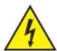
HAZARD:
- Do not open or modify the unit.
- If your device no longer functions properly, if liquids or objects get inside it or if it has been damaged in any other way, switch it off immediately and disconnect it from the mains. The device may be repaired only by authorised repair technicians.
- For devices of protection class 1, the protective conductor must be connected correctly. Never disconnect the protective conductor. Devices of protection class 2 do not have a protective conductor.
- Ensure that live cables are not kinked or otherwise mechanically damaged.
- Never bypass the unit fuse.
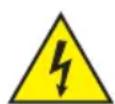
WARNING:
- The device may not be operated if it shows obvious signs of damage.
- The device may only be installed in a voltage-free state.
- If the mains cable of the device is damaged, do not operate the device.
- Permanently connected power cables may only be replaced by a qualified person.
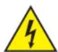
ATTENTION:
- Do not operate the unit if it has been exposed to large temperature fluctuations (for example, after transport). Moisture and condensation can damage the device. Switch on the device only when it has reached room temperature.
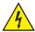
- Make sure that the voltage and frequency of the mains supply correspond to the values indicated on the unit. If the device has a voltage selector switch, do not connect the device until it has been set correctly. Use only suitable power cables.
- To disconnect the unit from the mains at all poles, it is not sufficient to press the on/off switch on the unit.
- Make sure that the fuse used corresponds to the type printed on the unit.
- Make sure that appropriate measures have been taken against overvoltage (e.g. lightning strike).
- Observe the specified maximum output current on units with Power Out connection. Ensure that the total current consumption of all connected devices does not exceed the specified value.
- Replace pluggable mains cables only with original cables.

HAZARD:
- Danger of suffocation! Plastic bags and small parts must be kept out of reach of persons (including children) with reduced physical, sensory or mental capabilities.
- Danger from falling down! Make sure that the device is securely installed and will not fall down. Only use suitable stands or mounts (particularly for fixed installations). Ensure that accessories are properly installed and secured. Ensure that applicable safety regulations are observed.

WARNING:
- Use the device only in the manner intended.
- Operate the device only with the accessories recommended and intended by the manufacturer.
- During installation, observe the safety regulations applicable in your country.
- After connecting the unit, check all cable routes to avoid damage or accidents, e.g. due to tripping hazards.
- Always observe the specified minimum distance to normally flammable materials! Unless explicitly stated, the minimum distance is 0.3 m.

CAUTION:
- In the case of moving components such as mounting brackets or other moving components, there is a possibility of jamming.
- In the case of units with motor-driven components, there is a risk of injury from the movement of the unit. Sudden movement of the device can cause shock reactions.
- The housing surface of the device can become very hot during regular operation. Ensure that accidental touching of the housing is not possible. Always allow the lamp to cool sufficiently before removal, maintenance work and charging etc.

ATTENTION:
- Do not install or operate the device near any radiators, heat registers, stoves or other heat sources. Ensure that the device is always installed in such a way that it is sufficiently cooled and cannot overheat.
- Do not place ignition sources such as burning candles near the device.
- Ventilation openings must not be covered and fans must not be blocked.
- Use the original packaging or packaging provided by the manufacturer for transport.
- Avoid shock or impact to the unit.
- Observe the IP protection class as well as the ambient conditions such as temperature and humidity according to the specification.
- Devices can be constantly further developed. In the event of deviating information on operating conditions, performance or other device properties between the user manual and the device labelling, the information on the device always takes priority.
- The unit is not suitable for tropical climates and for operation above 2000 m above sea level.
- Unless explicitly stated, the unit is not suitable for operation in marine conditions.

NOTE:
For conversion or retrofit sets or accessories provided by the manufacturer, it is essential to observe the instructions included.

CAUTION! IMPORTANT INFORMATION REGARDING LIGHTING PRODUCTS!
- Never look directly into the beam of light, not even for a short period of time.
- Never look into the beam of light using optical devices such as a magnifying glass.
- Stroboscopic effects may cause epileptic seizures in susceptible individuals!
- Permanently installed lamps are built into these lighting units. These may not be replaced by the user. The lamps contained in this lighting unit may only be replaced by the manufacturer, its service partner, or a similarly qualified person.



SIGNAL TRANSMISSION BY RADIO (E.G. W-DMX OR AUDIO RADIO SYSTEMS):
The quality and performance of wireless signal transmissions generally depends on the ambient conditions.
The following factors can impact range and signal stability, for example:
Shielding (e.g. masonry, metal structures, water)
High volume of radio traffic (e.g. powerful wireless LAN networks)
Interference
Electromagnetic radiation (e.g. LED video screens, dimmers)
All range specifications refer to free-field application with visual contact and without interference!
The operation of transmission systems is subject to official regulations. These may vary from region to region and must be checked by the operator before use (e.g. radio frequency and transmission power).

Devices with wireless signal transmission are not suitable for use in sensitive areas in which radio operation can lead to potential detrimental effects. These include:
- Hospitals, health centres or other healthcare facilities that provide patient treatment with skilled personnel and equipment.
• Hazardous areas Class I, II and III - Restricted areas
- Military facilities
- Aircraft or vehicles
- Areas where the use of mobile phones is prohibited

TRANSMISSION VIA W-DMX
WARNING: Ingeneral, wireless DMX transmission must not be used for applications with safety-related factors that could result in personal injury or property damage in the event of failure.
This applies in particular to moving scene or traverse structures, DMX-controlled motors/lifts or lifting devices for operating DMX-operated platform lifts, hydraulic systems or comparable moving components.
Furthermore, wireless DMX transmission must not be used to trigger flame or pyrotechnic devices, explosion-driven effects, or to control gas or liquid effects. These include CO2 cannons, confetti shooters, water effects or similar.

NOTES ON PORTABLE OUTDOOR DEVICES
- Temporary operation! Event equipment is generally only designed for temporary operation.
- Continuous operation or permanent structural installation – particularly outdoors – can impair the function, surfaces and seals and accelerate material fatigue.
- Damage to the surface coating can impair the device's corrosion protection. Damaged surface coating (e.g. scratches) must be promptly repaired by suitable measures.
INCLUDED
Remove the product from the packaging and remove all packaging material.
Please check the completeness and integrity of the delivery and notify your distribution partner immediately after purchase if the delivery is not complete or if it is damaged.
The packaging includes:
▶ 1 x S2 IP Softlight spotlight
▶ 1 x U-bracket (pre-assembled)
▶ 1 x Omega double bracket
▶ 1 x standard diffuser disc (pre-assembled)
▶ 1 x 28 mm TV spigot incl. fastening screw M10 plus disc spring and washer
1x Power cord
▶ User manual
INTRODUCTION
LED SOFTLIGHT PANEL - IP65
CLS2IP
CONTROL FUNCTIONS:
1 CH DIM, 2CH DIM 16bit, 2CH CCT, 4CH CCT, 3CH RGB, 4CH RGBW, 8CH RGBW 16bit, 6CH HSI-CCT, 7CH Preset, 7CH RGB-CCT, 7CH Direct, 10CH Direct-CCT, 10CH HSI-CCT, 16CH Direct-CCT, 18CH Full Access, 6CH x y and 16CH Pixel DMX control
DMX512.
ArtNet
sACN
W-DMX™
RDM
Master / slave operation
Standalone functions
FEATURES:
Protection class IP65. RGB+WW colour spectrum. 272 0.5 W LEDs per colour (4 x 272). DMX512. ArtNet. sACN. W-DMX™. 5-pin DMX connectors. RJ45 connectors. Blackout button. Push-button with direct access to the CCT operating mode. 2 freely assignable user buttons. U-bracket and 28 mm TV spigot included. One standard diffuser panel included. Extensive range of optional accessories.
The spotlight features the RDM standard (Remote Device Management). This remote device management enables the status query and configuration of RDM end devices via an RDM-capable controller, such as the optionally available Cameo UNICON (item number CLIREMOTE).
The Cameo UNICON also allows access to the entire fixture menu.
CONNECTIONS, OPERATING AND DISPLAY ELEMENTS
text_image
17 16 18 BATTERY IN 23V - 36V 7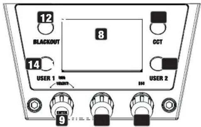
text_image
12 BLACKOUT 8 CCT 14 USER 1 输入 SELECT E66 USER 2 ENTER 9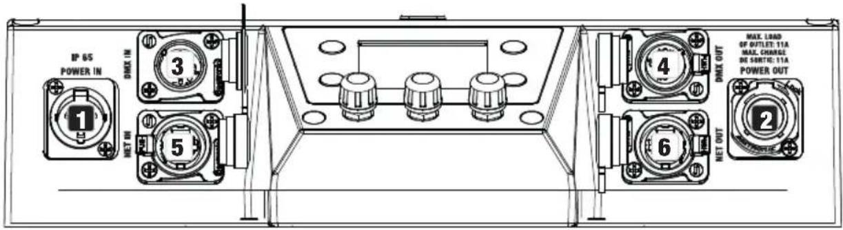
text_image
IP 65 POWER IN 1 3 NET IN 5 4 MAX. LOAD SP OUTLET: 11A MAX. CHANGE DE SOUT: 11A POWER OUT 6 NET OUT 21 POWER IN
IP65 mains input socket with rubber sealing cap (TRUE1 compatible). Operating voltage 100–240 V AC/50–60 Hz. Connection via supplied power cable (when not in use, always close with rubber sealing cap).
2 POWER OUT
IP65 mains output socket with rubber sealing cap (TRUE1 compatible). Facilitates power supply to other CAMEO spotlights. Ensure that the total current consumption of all connected devices does not exceed the value specified on the device in amperes (A) (when not in use, always close with the rubber sealing cap).
3 DMX IN
Male IP65 5-pin XLR socket for connecting a DMX control device (e.g. DMX console; when not in use, always close with the rubber sealing cap).
4 DMX OUT
Female IP65 5-pin XLR socket for sending DMX control signal (when not in use, always close with the rubber sealing cap).
5 NET IN
RJ45 network connector with IP65 protection for connecting to an ArtNet or sACN network. Use IP65 category CAT-5e or better cable to set up the network (always close with the rubber sealing cap when not in use).
6 NET OUT
RJ45 network connection with IP65 protection for forwarding the control signal. Use IP65 category CAT-5e or better cable to set up the network (always close with the rubber sealing cap when not in use).
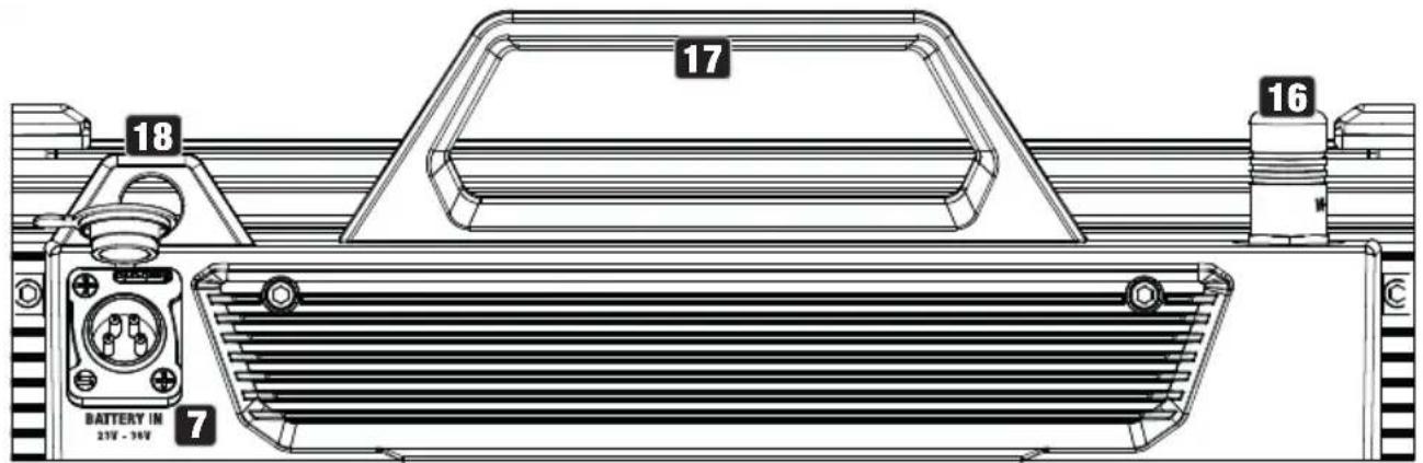
7 BATTERY IN
Male 4-pin XLR socket with IP65 protection for connecting external batteries (always close with the rubber sealing cap when not in use; batteries not included). A double V-mount adapter with connection cable is optionally available (item number CLSVMOUNTAP).
8 LC DISPLAY
The LC display shows the currently activated operating mode (main display), the menu items in the menu and the numerical value or operating status in certain menu items. If no entry is made within approximately one minute, the display automatically changes to the main display. Note on the main display in the operating modes with external control: As soon as the control signal is interrupted, the characters in the display start flashing; if the control signal is present again, the flashing stops.
9 DIM / SELECT / ENTER
Rotary-push encoder for the adjustment and control of the spotlight.
DIM - In the stand-alone modes CCT, HSI, Direct LED, Colour Coordinates, Gel, User Colour, Play Loop and Light Simulation, the encoder has the function of the master dimmer (turn encoder).
SELECT - Turn the encoder to select the menu items on the menu level and change a value in a menu item (e.g. DMX start address).
ENTER - 1. Pressing ENTER takes you to the menu level for selecting the operating mode. 2. You move down one level in the menu structure. 3. Press ENTER to confirm a value or status change, such as changing the DMX start address.
10 The function of the middle turn-push encoder (turn and push) is shown in the corresponding menu item in the centre of the display (line centre = turn, line bottom = push).
11 ESC - If the press function of the right-hand rotary-push encoder is not explicitly shown at the bottom right of the display, pressing the encoder has the function of moving up one level in the menu structure.
12 BLACKOUT
Shortcut button with blackout function. Press the button to activate Blackout. Press the button again to deactivate Blackout.
13 CCT
Shortcut button for direct access to stand-alone CCT mode.
14 USER 1
Button 1 can be freely assigned with a stand-alone operating mode (see menu item Settings -> User Buttons).
15 USER 2
Button 2 can be freely assigned with a stand-alone operating mode (see menu item Settings -> User Buttons).
16 W-DMX
Antenna for W-DMX ^TM control.
17 CARRY HANDLE
Ergonomic carrying handle for comfortable transport.
18 SECURING LUG
Use a suitable safety rope to secure the spotlight when mounting it overhead.
OPERATION
PLEASE NOTE
When the spotlight is started, "Welcome to Cameo", the model name and the software version are shown in the display for a short time. After this process, the spotlight is ready for operation and the previously activated operating mode is launched.
DISPLAY MAIN DISPLAY IN DMX MODE
The main display in DMX mode shows the currently set DMX start address, DMX mode and other information (see illustration).
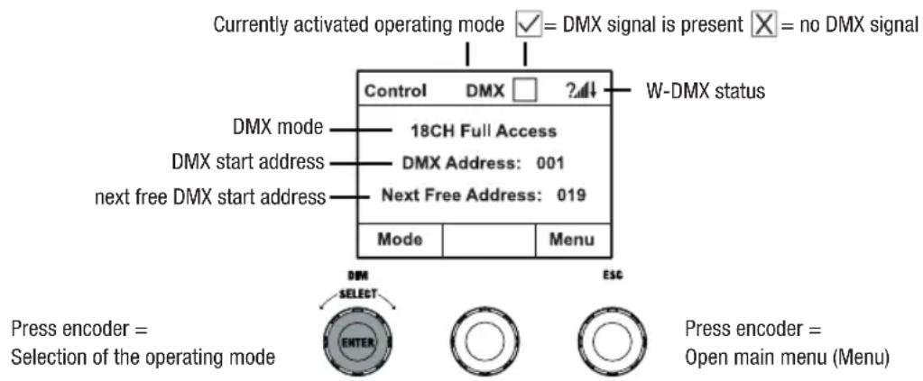
text_image
Currently activated operating mode ✓ = DMX signal is present ✗ = no DMX signal Control DMX □ ?4↓ W-DMX status DMX mode 18CH Full Access DMX start address DMX Address: 001 next free DMX start address Next Free Address: 019 Mode Menu Press encoder = Selection of the operating mode DMM SELECT ENTER ESC Press encoder = Open main menu (Menu)DISPLAY MAIN DISPLAY IN THE ARTNET OR SACN OPERATING MODE
The main display in Artnet or sACN mode shows the DMX mode, the currently set DMX start address, the IP address and universe group and the universe (see illustration).
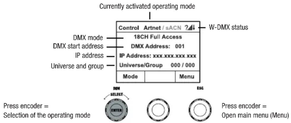
text_image
Currently activated operating mode Control Artnet / sACN ? W-DMX status DMX mode 18CH Full Access DMX start address DMX Address: 001 IP address IP Address: xxx.xxx.xxx.xxx Universe/Group 000 / 000 Universe and group Mode Menu Press encoder = Selection of the operating mode ESC Press encoder = Open main menu (Menu)W-DMX™
To pair a W-DMX receiver with a W-DMX compatible transmitter, W-DMX must be switched on in the Settings menu of the receiver under Wireless Settings (WDMX State -> On), the unit must be configured as a receiver (Operating Mode -> Receive) and the command Reset must be executed (Receive Reset -> Yes). The receiver is now in pairing standby and waiting for a pairing request from a transmitter. Start the pairing by selecting Link in the menu of the transmitter and confirming; the pairing now takes place automatically. In the same way, several receivers can be paired simultaneously or one after the other to a transmitter (e.g. for master/slave operation). A W-DMX connection is always maintained until the connection is disconnected by means of the Reset command in the receiver or the Unlink command in the transmitter, regardless of whether a device has been disconnected from the power supply in the meantime.
W-DMX™ STATUS
| ?↓ | ↓ | ↓ | ↓ | ↑G3 | ↑G4S | ↑G3 | ↑G4S | |
| W-DMX deactivated | W-DMX as receiver activated, not paired | W-DMX as receiver activated and paired, Transmitter switched off or out of range | W-DMX as receiver activated and paired, no DMX signal | W-DMX as receiver activated and paired, DMX signal is present | W-DMX as transmitter with G3 standard activated, DMX signal is present | W-DMX as transmitter with G4s standard activated, DMX signal is present | W-DMX as transmitter with G3 standard activated, no DMX signal | W-DMX as transmitter with G4s standard activated, no DMX signal |
SETTING DMX START ADDRESS (DMX address)
Starting from the main display, press the rotary-push encoder to enter the main menu. Turn the left encoder (SELECT) to select the menu item DMX Address (note the selection arrow on the left) and confirm by pressing the encoder (ENTER). You can now configure the DMX start address as required by rotating the encoder (the highest value depends on the selected DMX mode). Confirm the entry by pressing the left encoder (ENTER), this also automatically takes you back to the main display and the DMX operating mode is activated. At the same time, the DMX start address following the selected start address plus the channel number of the selected DMX mode is displayed (Next Free Address). The menu item for selecting the desired DMX mode can be reached directly from the menu item DMX Address by pressing the middle rotary-push encoder (DMX mode); the previously set DMX start address is automatically saved.
CONFIGURING DMX MODE (DMX Mode)
Starting from the main display, press the rotary-push encoder to enter the main menu (MENU). Turn the left encoder (SELECT) to select the menu item DMX Mode (note the selection arrow on the left) and confirm by pressing the left encoder (ENTER). Now you can select the desired DMX mode by turning the left encoder. Confirm the selection by pressing the left encoder (ENTER), this also automatically takes you back to the main display and the DMX operating mode is activated. The menu item for setting the desired DMX start address can be reached directly from the menu item DMX Mode by pressing the middle rotary-push encoder (DMX Address); the previously selected DMX mode is automatically saved. Tables with the channel assignment of the different DMX modes can be found in these instructions under DMX CONTROL.
ENABLE EXTERNAL CONTROL VIA DMX, ARTNET AND SACN
Starting from the main display, press the left-hand rotary-push encoder to access the menu for selecting the operating mode. Turn the left encoder (SELECT) to select DMX (note the selection arrow on the left) and confirm by pressing the left encoder (ENTER). Now the control protocol that was preselected in the menu item Protocol in the main menu is activated (DMX512 / Artnet / sACN).
To configure the two control protocols Artnet and sACN as desired, press the right encoder (Menu), then select Protocol and confirm (Enter). Select the desired protocol, confirm, now select the submenu items for setting and confirm again (see table).
| Protocol Artnet and sACN | ||
| Select by turning the encoder, confirm by pressing, change value or status by turning, confirm by pressing. Back with ESC. | ||
| Universe Setting the Universe 000-255 | ||
| Universe Group Setting the Universe Group 000-127 | ||
| DMX Address Setting the DMX start address 001-512 | ||
| DMX Mode Selecting the DMX mode 1CH Dim ... 16CH Pixel | ||
| IP Address | Setting the IP address:1. Set block with middle encoder2. Set block with right encoderPress middle encoder (Next Range)3. Set block with middle encoder4. Set block with right encoder | xxx.xxx.xxx.xxx.xxx |
| IP Address Press the left encoder to save (Enter) xxx.xxx.xxx.xxx.xxx | ||
| Subnet Mask | Setting the subnet mask:1. Set block with middle encoder2. Set block with right encoderPress middle encoder (Next Range)3. Set block with middle encoder | xxx.xxx.xxx.xxx.xxx |
| 4. Set block with right encoderPress left encoder to save (Enter) | xxx.xxx.xxx.xxx.xxx | |
| Signal Routing | Forwarding the control signal via XLR Out Send to XLR | |
| Forwarding the control signal via W-DMX Send to WDMX | ||
| Forwarding the control signal via XLR Out and W-DMX | Send to Both | |
| Control via XLR with Artnet or sACN signal interruption | Backup by XLR | |
STANDALONE OPERATING MODE CCT (Correlated Colour Temperature)
Starting from the main display, press the left-hand rotary-push encoder to access the menu for selecting the operating mode. Turn the left encoder (SELECT) to select CCT (note the selection arrow on the left) and confirm by pressing the left encoder (ENTER). You can now set the brightness (DIM), colour temperature (CCT) and hue (Tint) by turning the three rotary-push encoders (see illustration).
| Control | CCT | |
| DIM | CCT | Tint |
| 100% | 3500K | 0.0 |
| Mode | Menu |
Turn encoder =
Set brightness (DIM)
Press encoder =
Selection of the operating mode
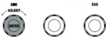
text_image
DBM SELECT ENTER ESCTurn encoder =
Setting the colour tone (Tint)
Press encoder =
Open main menu (Menu)
Turn encoder =
Set colour temperature (CCT)
STANDALONE OPERATING MODE HSI (Hue - Saturation - Intensity)
Starting from the main display, press the left-hand rotary-push encoder to access the menu for selecting the operating mode. Turn the left encoder (SELECT) to select HSI (note the selection arrow on the left) and confirm by pressing the left encoder (ENTER). You can now set the brightness (DIM), hue (HUE) and saturation (SAT) by turning the three rotary-push encoders (see illustration).
Turn encoder =
Set brightness (DIM)
Press encoder =
Selection of the operating mode
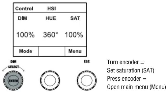
text_image
Control HSI DIM HUE SAT 100% 360° 100% Mode Menu DIM SELECT ENTER ESC Turn encoder = Set saturation (SAT) Press encoder = Open main menu (Menu)Turn encoder =
Setting the colour tone (HUE)
STANDALONE OPERATING MODE DIRECT LED (RGBW colour mixing)
Starting from the main display, press the left-hand rotary-push encoder to access the menu for selecting the operating mode. Turn the left encoder (SELECT) to select Direct LED (note the selection arrow on the left) and confirm by pressing the left encoder (ENTER). Now set the total brightness (DIM) and the intensity of R, G, B and W using the three rotary-push encoders (see illustration).
Turn encoder =
Set overall brightness (DIM)
Press encoder =
Selection of the operating mode
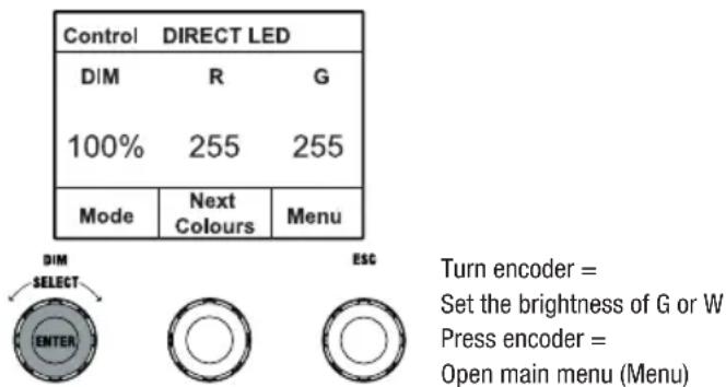
text_image
Control DIRECT LED DIM R G 100% 255 255 Mode Next Colours Menu DIM SELECT ENTER ESC Turn encoder = Set the brightness of G or W Press encoder = Open main menu (Menu)Turn encoder =
Set the brightness of R or B
Press encoder =
switch between R+G and B+W (Next Colours)
STANDALONE OPERATING TYPE COLOURCOORDINATES
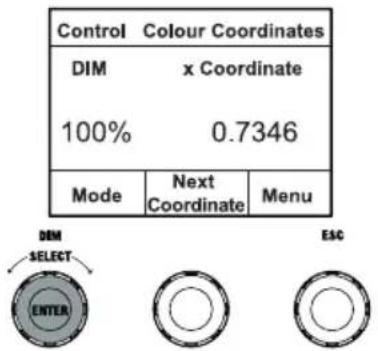
Starting from the main display, press the left-hand rotary-push encoder to access the menu for selecting the operating mode. Turn the left encoder (SELECT) to select Colour Coordinates (note the selection arrow on the left) and confirm by pressing the left encoder (ENTER). You now set the overall brightness (DIM) and the x and y coordinates with the help of the three rotary-push encoders (see illustration).
Turn encoder =
Set overall brightness (DIM)
Press encoder =
Selection of the operating mode
text_image
Control Colour Coordinates DIM x Coordinate 100% 0.7346 Mode Next Coordinate Menu DIM SELECT ENTER ESCTurn encoder =
Set digit 3 and 4 after the decimal point
Press encoder =
Open main menu (Menu)
Turn encoder =
Set digit 1 and 2 after the decimal point
Press encoder =
switch between x and y (Next Coordinate)
STANDALONE MODE COLOUR PRESETS (GEL)
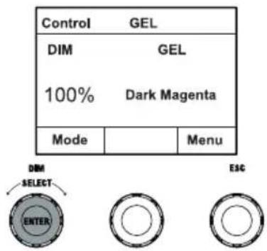
Starting from the main display, press the left-hand rotary-push encoder to access the menu for selecting the operating mode. Turn the left encoder (SELECT) to select GEL (note the selection arrow on the left) and confirm by pressing the left encoder (ENTER). Now set the overall brightness (DIM) using the left encoder and select one of the available Lee-Filter colour presets (Dark Magenta to Rose Pink) using the middle rotary-push encoder (see illustration).
Turn encoder =
Set overall brightness (DIM)
Press encoder =
Selection of the operating mode
text_image
Control GEL DIM GEL 100% Dark Magenta Mode Menu DIM SELECT ENTER ESCPress encoder =
Open main menu (Menu)
Turn encoder =
Select colour preset
STANDALONE OPERATING MODE USER COLOURS (User Colour)
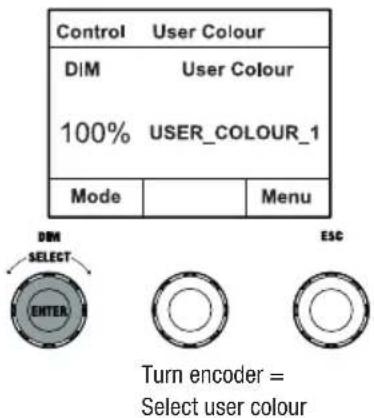
Starting from the main display, press the left-hand rotary-push encoder to access the menu for selecting the operating mode. Turn the left encoder (SELECT) to select User Colour (note the selection arrow on the left) and confirm by pressing the left encoder (ENTER). Now set the brightness (DIM) using the left encoder and select one of the eight user colours (USER_COLOUR_1 to USER_COLOUR_8) using the middle rotary-push encoder (see illustration). The user colours can be edited individually (Main Menu -> Edit User Colour).
Turn encoder = Set overall brightness (DIM) Press encoder = Selection of the operating mode
text_image
Control User Colour DIM User Colour 100% USER_COLOUR_1 Mode Menu DIM SELECT ENTER ESC Turn encoder = Select user colourPress encoder = Open main menu (Menu)
EDIT STANDALONE OPERATING MODE USER COLOUR (Edit User Colour)
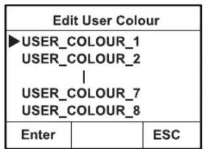
Starting from the main display, press the rotary-push encoder to enter the main menu (MENU). Turn the left encoder (SELECT) to select the menu item Edit User Colour (note the selection arrow on the left) and confirm by pressing the left encoder (ENTER). Now you can select one of the 8 user colours by turning the left encoder and confirm the selection by pressing the left encoder (ENTER).
| Menu | ||
| Protocol Stand Alone EZ Remote Slave ►Edit User Colour | ||
| Enter | ESC | |
text_image
Edit User Colour ►USER_COLOUR_1 USER_COLOUR_2 | USER_COLOUR_7 USER_COLOUR_8 Enter ESC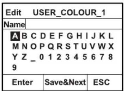
text_image
Edit USER_COLOUR_1 Name A B C D E F G H I J K L M N O P Q R S T U V W X Y Z _ 0 1 2 3 4 5 6 7 8 9 Enter Save&Next ESCNow give the user colour an individual name of up to 12 digits by turning the left encoder to select a letter, the underscore or a number for the first digit of the name and confirm by pressing the left encoder. This is followed by the input for the second digit and so on. When the name is complete, press the middle encoder (Save&Next) to move to the next editing step. If you press "Save&Next" before selecting a letter, the underscore, or a number for the first digit, the previous name is retained and you move immediately to the next editing step.
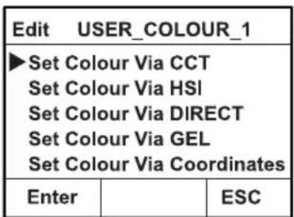
Now decide in which way you want to create the user colour, select the desired mode by turning the left encoder (SELECT) (CCT, HSI, DIRECT, GEL and Coordinates) and confirm by pressing the left encoder (ENTER).
text_image
Edit USER_COLOUR_1 ►Set Colour Via CCT Set Colour Via HSI Set Colour Via DIRECT Set Colour Via GEL Set Colour Via Coordinates Enter ESCNow set the desired colour as described in the instructions for the respective standalone mode and press the left encoder (ENTER/Save) to confirm.
STANDALONE OPERATING MODE COLOUR SEQUENCE (Play Loop)
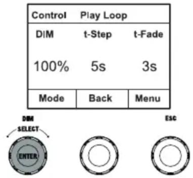
Starting from the main display, press the left-hand rotary-push encoder to access the menu for selecting the operating mode. Turn the left encoder (SELECT) to select Play Loop (note the selection arrow on the left) and confirm by pressing the left encoder (ENTER). Select one of the 8 pre-programmed but individually editable colour sequences by turning the left encoder again. Confirm the selection by pressing the left encoder (ENTER). Now set the brightness (DIM) of the colour sequence using the left encoder, the step duration (0.1 seconds to 21 minutes and 2 random modes) and the fade time (0 seconds to 18 minutes and 2 random modes) using the middle and right encoders (see illustration). The individual settings and renaming of the colour sequences can be done in the menu item Edit Loop in the main menu.
Turn encoder =
Set brightness (DIM)
Press encoder =
Selection of the operating mode
text_image
Control Play Loop DIM t-Step t-Fade 100% 5s 3s Mode Back Menu DIM SELECT ENTER ESCTurn encoder =
Setting the fade time (t-fade)
Press encoder =
Open main menu (Menu)
Turn encoder =
Set step duration (t-step)
Press encoder =
Back to the colour sequence selection (Back)
EDIT STANDALONE OPERATING MODE PLAY LOOP (Edit Loop)
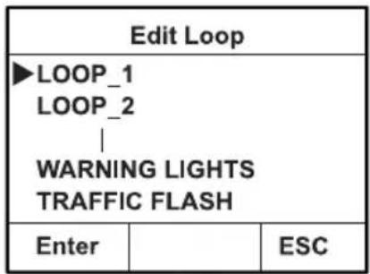
Starting from the main display, press the rotary-push encoder to enter the main menu (MENU). Turn the left encoder (SELECT) to select the menu item Edit Loop (note the selection arrow on the left) and confirm by pressing the left encoder (ENTER). Now you can select one of the 8 colour sequences by turning the left encoder and confirm the selection by pressing the left encoder (ENTER).
| Menu | ||
| Stand AloneEZ RemoteSlaveEdit User Colour▶Edit Loop | ||
| Enter | ESC | |
text_image
Edit Loop ►LOOP_1 LOOP_2 | WARNING LIGHTS TRAFFIC FLASH Enter ESC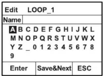
text_image
Edit LOOP_1 Name A B C D E F G H I J K L M N O P Q R S T U V W X Y Z _ 0 1 2 3 4 5 6 7 8 9 Enter Save&Next ESC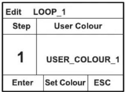
text_image
Edit LOOP_1 Step User Colour 1 USER_COLOUR_1 Enter Set Colour ESCNow give the colour sequence an individual name of up to 12 digits by turning the left encoder to select a letter, the underscore or a number for the first digit of the name and confirm by pressing the left encoder. This is followed by the input for the second digit and so on. When the name is complete, press the middle encoder (Save&Next) to move to the next editing step. If you press "Save&Next" before selecting a letter, the underscore, or a number for the first digit, the previous name is retained and you move immediately to the next editing step.
Select a step of the 8-step sequence (Step 1 - Step 8) by turning the left encoder, then set the colour of the step. Now select one of the colours in the standalone mode User Colour or Blackout or Skip Step (Step 3 - 8) by turning the middle encoder. Proceed in the same way to set the colours of the other steps. Complete the process and save the sequence by pressing the left encoder (ENTER).
STANDALONE OPERATING MODE LIGHT SIMULATION (Light Simulation)
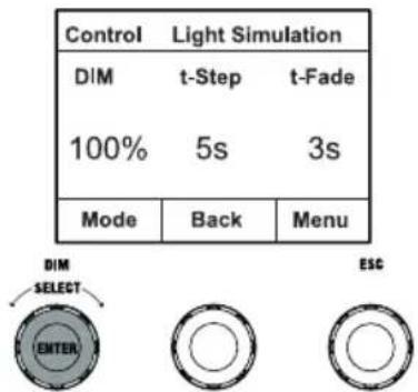
Starting from the main display, press the left-hand rotary-push encoder to access the menu for selecting the operating mode. Turn the left encoder (SELECT) to select Light Simulation (note the selection arrow on the left) and confirm by pressing the left encoder (ENTER). Select one of the 8 pre-programmed simulations by turning the left encoder again. Confirm the selection by pressing the left encoder (ENTER). Now set the brightness (DIM) using the left encoder, the step duration (0.1 seconds to 21 minutes and 2 random modes) and the fade time (0 seconds to 18 minutes and 2 random modes) using the middle and right encoders (see illustration).
Turn encoder =
Set brightness (DIM)
Press encoder =
Selection of the operating mode
text_image
Control Light Simulation DIM t-Step t-Fade 100% 5s 3s Mode Back Menu DIM SELECT ENTER ESCTurn encoder = Setting the fade time (t-fade) Press encoder = Open main menu (Menu)
Turn encoder = Set step duration (t-step) Press encoder = back to the colour sequence selection (Back)
EZ REMOTE CONTROL VIA CAMEO UNICON (optionally available)
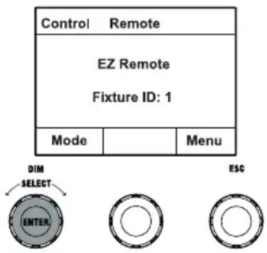
Starting from the main display, press the left-hand rotary-push encoder to access the menu for selecting the operating mode. Turn the left encoder (SELECT) to select EZ Remote (note the selection arrow on the left) and confirm by pressing the left encoder (ENTER). Now set the desired fixture ID (Fixture ID 1 - 8) by turning the left encoder (SELECT) and confirm by pressing the left encoder (ENTER).
Connect the spotlight and UNICON using a DMX cable, select DMX Control in the UNICON menu, then EZ Remote, and enter the same unit ID. Now control the spotlight using RGB, GEL, CCT or HSI. By assigning different unit IDs, up to eight spotlights (or spotlight groups) can be controlled separately via UNICON.
text_image
Control Remote EZ Remote Fixture ID: 1 Mode Menu DIM SELECT ENTER ESCSLAVE MODE
Starting from the main display, press the left-hand rotary-push encoder to access the menu for selecting the operating mode. Turn the left encoder (SELECT) to select the slave (note the selection arrow on the left) and confirm by pressing the left encoder (ENTER). Connect the slave and the master units (same model, same software version) with a DMX cable and enable a standalone mode on the master unit. The slave unit will now follow the master unit. The control signal can alternatively be transmitted via W-DMX. Enable W-DMX in both the master and slave units. Configure the master unit as transmitter, the slave unit as receiver and pair the units (Settings -> Wireless Settings).
SYSTEM SETTINGS (Settings)
Starting from the main display, press the right-hand rotary-push encoder to access the menu for selecting the operating mode (Menu). Turn the left encoder (SELECT) to select Settings (note the selection arrow on the left) and confirm by pressing the left encoder (ENTER).
This takes you to the submenu for setting the submenu items (see table, select by turning the left encoder, confirm with ENTER, change value or status by turning the left encoder, confirm with ENTER).
Settings
| Wireless settings | = | W-DMX Settings | WDMX State | On Activate W-DMX | |
| Off W-DMX deactivated | |||||
| Operating Mode | Receive W-DMX mode: Receiver | ||||
| Transmit W-DMX mode: Transmitter | |||||
| Transmitting Mode | G3 G3 transmission standard | ||||
| G4s G4s transmission standard | |||||
| Link | Link | Pair with W-DMX devices. W-DMX must be enabled on all devices, and the pairing with a transmitter be retained (Receive Reset). | |||
| Unlink Unpair all devices | |||||
| Receive Reset | No Cancel operation | ||||
| Yes | Terminate the connection to all paired W-DMX transmitters and set them to pairing standby | ||||
| Display Reverse | = | Rotate display | Off No display | rotation | |
| On | Display is rotated by 180° (e.g. for overhead installation) | ||||
| Display Off Timer | = | Display Lighting | Always On On | permanently | |
| Off after 20s | Deactivates after approximately 20 seconds of inactivity | ||||
| Signal Fail | = | Operational status with DMX signal fault | Hold Last command is retained | ||
| Blackout Activates blackout | |||||
| User Colour 8 | Enables User Colour 8 | ||||
| Fade Out 10s | 10s fade to blackout | ||||
| Full On | All LEDs at maximum brightness | ||||
| Dimmer curve | = | Dimmer curve | Linear | Light intensity increases linearly with DMX value | |
| Exponential | Light intensity can be finely adjusted at lower DMX values and broadly adjusted at higher DMX values | ||||
| Logarithmic | Light intensity can be broadly adjusted at lower DMX values and finely adjusted at higher DMX values | ||||
| S-curve | Light intensity can be finely adjusted at lower and higher DMX values and broadly adjusted at medium DMX values | ||||
| Dimmer Response | = | Dimmoven | LED | Light responds abruptly to changes in DMX value | |
| Halogen | Light behaves like a halogen spotlight with slight brightness changes | ||||
| Autolock | Colour Calibration | PWM Frequency | Red Shift | ||||
| = | II | II | II | ||||
| Automatic locking of the controls | Colour calibration (cross-mode) | LED PWM frequency | Accurately mimics the colour drift of dimming a halogen spotlight. When dimming the spotlight, the colour temperature changes automatically to increasingly warm white tones and amber (and vice versa). | ||||
| 650Hz, 1530Hz, 3600Hz, 12kHz, 18.9kHz, 25kHz | Dim to Warm Colour drift is enabled | ||||||
| Select LED PWM frequency | |||||||
| Off Automatic | On | Smart Calibration | Factory Calibration | User Calibration | Individual colour calibration. Cross-mode brightness setting of R, G, B, A and L with values from 000 - 255. Set R and G with the middle and right encoder, then press the middle encoder (Next Colours) and set B and W again with the middle and right encoder. | ||
| Factory calibration of R, G, B and W | |||||||
| Merging factory and RAW calibration | |||||||
| Automatic locking of the controls after approximately 1 minute of inactivity. Display after operating attempt: "Locked!" Unlocking: Simultaneously press the middle and right encoder for approx. 5 seconds locking of the controls is disabled | |||||||
| Service | “=” | User Buttons | UC_Loops Reset | Factory Reset | Mirroring | Fan | ||||
| ==For service purposes only | “User Button 2 “” | == | == | == | == | == | ||||
| Assign one of the stand-alone modes (plus EZ Remote and Mode Selection) to User Button 1 and 2 | Reset User Colours and Loops | Reset settings | Mirror LED segments | FAN Control | ||||||
| User Button 1 | Reset User Colour_ | Reset User | Horizontal Mirror | Off Function d | Constant High | Constant Medium | Constant Low | Constant fan with greatly reduced brightness | ||
| EZ Remote, Mode Selection, HSI, Direct, Colour Coor-dinates, GEL, User Colour, Play Loop, Light Simulation | Reset User | Reset Now? Except User Colour_ | or LED segments horizontally | disabled | Constant high fan speed | constant average fan speed with reduced brightness, if necessary | constantly low fan speed with reduced brightness, if necessary | car automatic fan speed control | ||
| EZ Remote Control via CAMEO UNICON (optionally available) Mode Selection = Activate stand-alone oper-ating modes one after the other by repeated-ly pressing the user button | Reset the user colours and the loops to factory settings: Reset with Enter, cancel with ESC | Reset to factory settings (except user colours and loops): Perform reset with Enter, cancel with ESC | ||||||||
SYSTEM INFORMATION (System Info)
Starting from the main display, press the right-hand rotary-push encoder to access the menu for selecting the operating mode (Menu). Turn the left encoder (SELECT) to select System Info (note the selection arrow on the left) and confirm by pressing the left encoder (ENTER).
This takes you to the submenu for calling up the system information (see table, selection by turning the left encoder).
| System Info | |
| Main CPU Vx.xx | |
| DRV CPU Vx.xx | |
| LED Temp. xx°F xx°C | |
| Op. Hours xxxxx:xx h | |
| Display Always On / Off after 20s | |
| Signal Fail Hold / Blackout / User Colour 8 / Fade Out 10s | |
| Dim Curve Linear / Exponential / Logarithmic / S-Curve | |
| Dim Response LED / Halogen | |
| Red Shift Off / Dim to Warm | |
| PWM 650Hz / 1530Hz / 3600Hz / 12kHz / 18.9kHz / 25kHz | |
| Calibr. RAW / User / Factory / Smart | |
| User calibration R= | 000–255 |
| User calibration G= | 000–255 |
| User calibration B= | 000–255 |
| User calibration W= | 000–255 |
| Auto Lock | Off/On |
| Fan | Auto / Off / Constant Low / Constant Medium / Constant High |
| WDMX | Off/On |
| User Button 1 | EZ Remote / Mode Selection / HSI / Direct / Colour CoordinatesGEL / User Colour / Play Loop / Light Simulation |
| User Button 2 | EZ Remote / Mode Selection / HSI / Direct / Colour CoordinatesGEL / User Colour / Play Loop / Light Simulation |
| RDM UID xx xx xx xx xx xx | |
| MAC Addr. xxx.xxx.xxx.xxx.xxx | |

In order to be able to access all menu items in the fixture with the help of the Cameo UNICON DMX/RDM controller via Fixture Menu, the menu items Stand Alone (with all Stand Alone operating modes), EZ Remote and Slave are additionally located in the main menu in addition to the Mode menu.
MOUNTING THE TV SPIGOT ON THE U-BRACKET
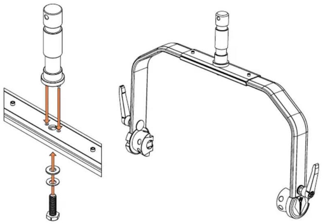
There is a bolt to the left and right of the M10 screw thread in the TV spigot. Insert the two bolts into the holes to the left and right of the screw hole in the U-bolt and screw the TV spigot to the U-bolt using the M10 screw, the disc spring and the washer (see illustration).
natural_image
Technical line drawing of a mechanical assembly with two views: one showing a bolted component inserted into a plate, the other showing a bracket with a handle and mounting feet (no text or symbols present)STATIVE MOUNTING

HAZARD Overhead mounting requires extensive experience, including the calculation of the load limit values of the installation material and regular safety inspection of all installation materials and spotlights. If you do not have these qualifications, do not attempt to perform an installation yourself. Refer instead to a qualified professional. There is a risk that devices that are incorrectly mounted and secured may come loose and fall down. This can cause serious injury or death.
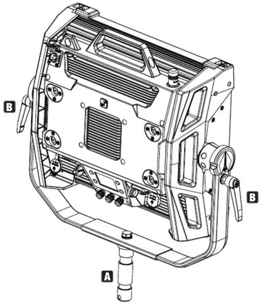
Use the 28 mm TV spigot previously mounted on the U-bracket for tripod mounting (Fig. A). Use a suitable tripod and follow the manufacturer's instructions (maximum load, vertical installation on a flat surface, etc.). To adjust the direction of radiation on a vertical plane, loosen the clamping levers mounted on the U-bracket slightly (Fig. B), set the desired direction of radiation and tighten the clamping levers again.
text_image
Technical diagram of a mechanical device with labeled parts A, B, and C, showing internal components like ventilation ducts and adjustment knobs.USING TV SPIGOTS FOR TRUSS MOUNTING

HAZARD Overhead mounting requires extensive experience, including the calculation of the load limit values of the installation material and regular safety inspection of all installation materials and spotlights. If you do not have these qualifications, do not attempt to perform an installation yourself. Refer instead to a qualified professional. There is a risk that devices that are incorrectly mounted and secured may come loose and fall down. This can cause serious injury or death.
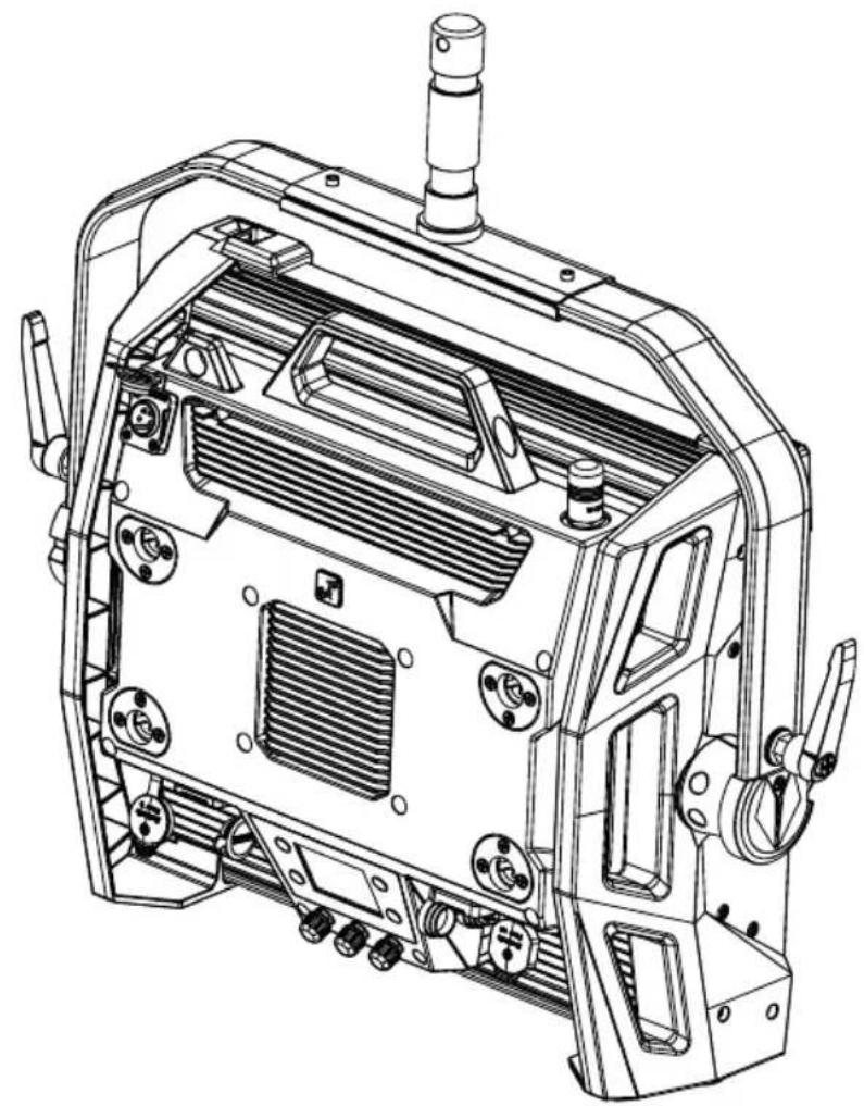
The 28 mm TV spigot previously mounted on the U-bracket can also be used for truss mounting. Use a suitable fastener and ensure a firm hold. To adjust the direction of radiation on a vertical plane, loosen the clamping levers mounted on the U-bracket slightly, set the desired direction of radiation and tighten the clamping levers again. Secure the headlamp to the safety eyelet using a suitable safety rope (fig. A).
natural_image
Technical line drawing of a mechanical device with internal components and mounting features (no text or symbols)OMEGA BRACKET
The Omega double bracket is included with the headlamp.

HAZARD Overhead mounting requires extensive experience, including the calculation of the load limit values of the installation material and regular safety inspection of all installation materials and spotlights. If you do not have these qualifications, do not attempt to perform an installation yourself. Refer instead to a qualified professional. There is a risk that devices that are incorrectly mounted and secured may come loose and fall down. This can cause serious injury or death.
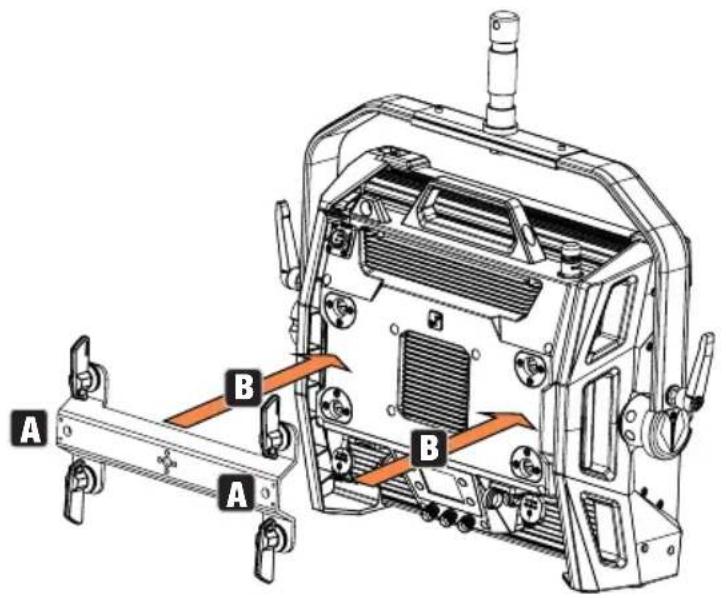
Truss mounting: First mount two suitable truss clamps (optionally available) to the left and right of the Omega bracket (fig. A) and then mount both together to the spotlight (fig. B). Turn the four locking levers about a quarter of a turn clockwise as far as they will go. Make sure that all connections are secure and secure the headlamp to the safety eyelet with a suitable safety rope (fig. C).
text_image
A B A B
natural_image
Technical diagram of a mechanical device with internal components and orange arrows indicating flow or movement (no text or symbols present)The Omega double bracket also serves as a mounting base for the optionally available accessory V-Mount Adapter (see OPTIONAL ACCESSORIES).
DIFFUSER PANEL
A standard diffuser disc is included in the scope of delivery. On the upper edge of the headlamp, there is a locking lever for the cover rail on the left and right (Fig. A and detailed view). Press the levers towards the centre of the enclosure and fold the cover rail upwards (Fig. B).
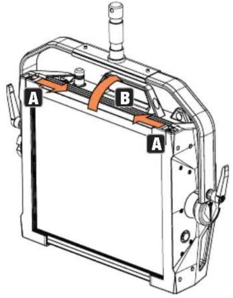
text_image
A B A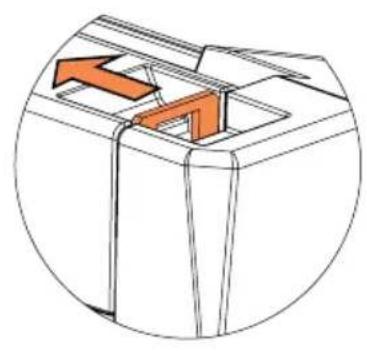
natural_image
Diagram of a mechanical component with an orange arrow indicating direction (no text or symbols)Now insert the diffuser disc from above into the rear, wide grooves of the installation compartment (Fig. C and detailed view).
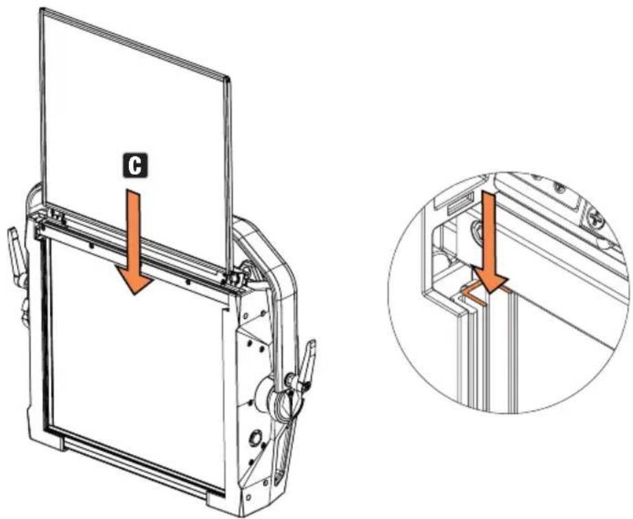
text_image
CNow fold the cover rail back down to close the installation compartment (Fig. D). Afterwards, the two locking levers must be pushed back towards the edge of the housing. During the procedure, make sure that the levers snap back into place correctly and that the diffuser disc is secured against falling out.
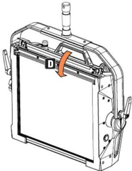
natural_image
Technical line drawing of a mechanical device with labeled component D (no text or symbols beyond label)
NOTES: A diffuser disc (or the Intensifier, optionally available) can also be installed in combination with one of the optionally available straightening grids and the Dark Filter, also optionally available (straightening grid + Dark Filter: narrow groove, diffuser discs + Intensifier: wide groove). The optionally available wing limiter can additionally be mounted on the headlamp.
OPTIONAL ACCESSORIES
CLS2IPBARNDOOR CLS2IPDARKFILTER CLS2IPHDFILTER
4-fold sash limiter Filter disc for
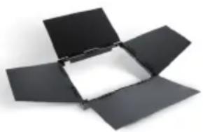
natural_image
Open black box with a white inner square, isolated on white background (no text or symbols)dark front
Filter disc for high diffusivity
natural_image
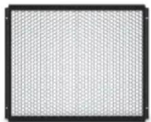
Blank white rectangle with black border (no text or symbols)CLS2IPINTENSIFIER CLS2IPHC30 CLS2IPHC60
Filter disk for narrow beam angle and increased illuminance

Straightening grille with 30 Beam angle
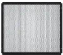
Straightening grille with 60 Beam angle
natural_image
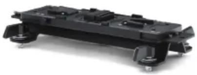
Close-up of a perforated metal panel with uniform grid pattern (no text or symbols)CLSVMOUNTAP CLS2IPPOYOKE
Double V-Mount Adapter Rod-operated
natural_image
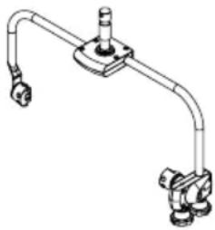
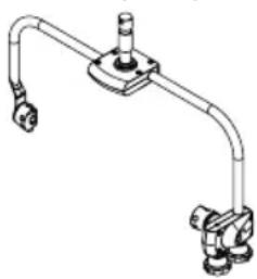
Black plastic mechanical component with mounting feet and mounting holes (no visible text or symbols)Mounting Bracket
natural_image
Pure mechanical pipe diagram without any text, numbers, or symbolsCARE, MAINTENANCE AND REPAIR
In order to ensure the long-term, proper functioning of the device, it must be regularly cleaned and, if necessary, maintained. The maintenance requirement depends on the intensity of use and the environment in which it is used.
We generally recommend a visual inspection before each operation. Furthermore, we recommend carrying out all the applicable maintenance measures specified below once every 500 operating hours or, in the case of a lower intensity of use, at the latest after one year. Warranty claims may be limited in the event of defects resulting from inadequate maintenance.
CARE (carried out by user)
WARNING! Before carrying out any care or maintenance, the power supply – and, if possible, all device connections – must be disconnected.

PLEASE NOTE! Improper care can lead to impairment of the device or even its destruction.
- Housing surfaces must be cleaned with a clean, damp cloth. Make sure that no moisture can penetrate the device.
- Air inlets and outlets must be regularly cleaned of dust and dirt. If compressed air is used, make sure that damage to the device is prevented (e.g. fans must be blocked in this case).
- Lines and plug contacts must be cleaned regularly and dust and dirt must be removed.
- In general, no cleaning agents or abrasive agents may be used, otherwise the surface finish may be damaged.
- Devices must generally be stored dry and protected from dust and dirt.
MAINTENANCE AND REPAIR (by qualified personnel only)
HAZARD! There are live components in the device. Even after disconnecting the mains connection, there may still be residual voltage in the device, for example, due to charged capacitors.

PLEASE NOTE! There are no user-serviceable assemblies in the device.

PLEASE NOTE! Maintenance and repair work may only be carried out by qualified specialist personnel authorised by the manufacturer. If in doubt, consult the manufacturer.

PLEASE NOTE! Improperly performed maintenance work may affect the warranty claim.
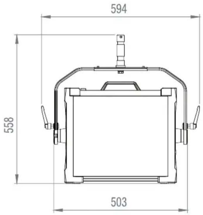
DIMENSIONS (MM)
text_image
558 503 594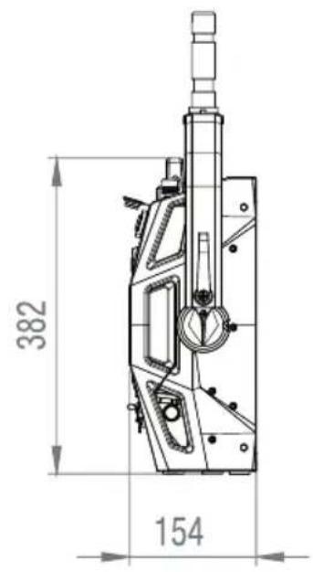
text_image
382 154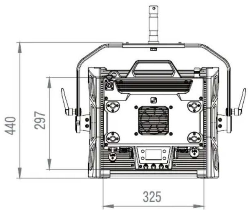
text_image
440 297 325TECHNICAL DATA
| Product number: CLS2IP | |
| Product type: LED spotlight | |
| Type: Softlight | |
| Colour spectrum: RGBWW | |
| LED number per colour: 272 | |
| LED type: 0.5 W Single Colour LEDs | |
| LED PWM frequency: 650 Hz, 1530 Hz, 3600 Hz, 25 kHz (adjustable) | |
| Beam angle (standard diffuser): Beam angle 102°; field angle 157° | |
| Control signal input: 5-pin XLR male, RJ45 | |
| Control signal output: 5-pin XLR female, RJ45 | |
| DMX functions: | Dimmer, Strobe, Red, Green, Blue, White, Hue,Saturation, x + y-coordinates, Colour Temperature,Tint, Colour Presets, Colour Presets Crossfade,Effect Macro, Effect Macro Speed, Device Settings |
| Control protocols: DMX512, W-DMX | TM, ArtNet, sACN, RDM |
| Standalone functions: | Direct, CCT, HSI, User Colour, GEL, xy-coordinates,Light Simulation, Loop |
| Operating controls: 3x turn-push encoder + 4x shortcut button | |
| Operating voltage: | 100–240 V AC/50–60 Hz |
| Power supply connection: | True 1 compatible sockets IN/OUT |
| Max. Output current POWER OUT: | 11 A |
| Battery input | 4-pole XLR |
| Battery operating voltage | 23-36 V |
| Power consumption: | 260 W |
| Illuminance @ 5m (standard diffuser) | 280 lx |
| Luminous flux (RGBW): | 16000 lm |
| Colour temperature range | 1800K - 10000K |
| CRI | >92 |
| REC2020 cover | 85,7% |
| IP protection class | IP65 |
| Ambient temperature (in operation): | -15°C to 45°C |
| MINIMUM DISTANCE TO ILLUMINATED SURFACE | 0.5 m |
| Minimum distance to normally flammable materials: | 0.5 m |
| Housing colour: | Black |
| Housing material: Magnesium alloy | |
| Housing cooling: | Temperature-controlled fan |
| Dimensions (W x H x D, including mounting bracket): | 594 x 440 x 154 mm |
Weight (without mounting bracket and diffuser): 12 kg
| Accessories included: | 1 x Mains cable1 x U-bracket (pre-assembled)1 x 28 mm TV spigot1 x Standard diffuser |
| Accessories (optional): | Honey Comb ( 30^/60^ )IntensifierBarndoorHeavy DiffuserDark FilterV-Mount Double AdaptorP.O. Yoke |
EXPLANATION OF IP PROTECTION CLASS
- An IP rating only reflects protection from solid objects and water. It does not describe general weather resistance, such as protection from UV radiation and temperature, etc.
- The first identification digit indicates protection from dust, solid objects and contact:
| IP2X Protected against solid foreign bodies ≥ 12.5 mm in diameter |
| IP3X Protected against solid foreign bodies ≥ 2.5 mm in diameter |
| IP4X Protected against solid foreign bodies ≥ 1.0 mm in diameter |
| IP5X Protected against dust in harmful quantities and completely protected against contact |
| IP6X Are dust-tight and completely protected against contact |
- The second identification digit indicates protection from water:
| IPX0 No | protection |
| IPX1 Protection against dripping water | |
| IPX2 Protection against dripping water when the device is tilted up to 15° | |
| IPX3 Protection against falling spray water up to 60° from the vertical | |
| IPX4 Protection against splashing water on all sides | |
| IPX5 Protection against water jets (nozzle) from any angle | |
| IPX6 Protection against strong water jets | |
| IPX7 Protection against temporary immersion | |
- In addition, some device-specific measures such as covers and sealing caps are necessary in order to achieve the specified protection class (e.g. protective caps on unused connections).
MINIMUM DISTANCE TO ILLUMINATED SURFACE
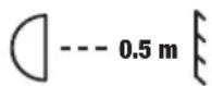
This symbol with distance information in metres (m) indicates the minimum distance of the luminaire to the illuminated surface. In this example, the distance is 0.5 m. The value valid for this unit can be found in the technical data in this manual and in the imprint on the unit housing!
MINIMUM DISTANCE TO NORMALLY FLAMMABLE MATERIALS
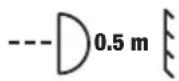
This symbol with distance indication in metres (m) indicates the minimum distance of the appliance to normally flammable materials. In this example, the distance is 0.5 m. For the value valid for this unit, please refer to the technical data in this manual!
DISPOSAL

Packaging:
- Packaging can be fed into the reusable material cycle using the usual disposal methods.
- Please separate the packaging in accordance with the disposal laws and recycling regulations in your country.
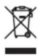
Device:
- This appliance is subject to the European Directive on Waste Electrical and Electronic Equipment as amended. WEEE Directive Waste Electrical and Electronic Equipment. Old appliances do not belong in household waste. The old device must be disposed of via an approved disposal company or a municipal disposal facility. Please observe the applicable regulations in your country!
- Observe all disposal laws and regulations applicable in your country.
- As a private customer, you can obtain information on environmentally-friendly disposal options from the seller of the product or the appropriate regional authorities.
MANUFACTURER'S DECLARATIONS
Manufacturer's warranty & limitation of liability
Adam Hall GmbH, Adam-Hall-Str. 1, D-61267 Neu Anspach
E-mail: Info@adamhall.com / +49 (0)6081 / 9419-0
Our current warranty conditions and limitation of liability can be found at:
https://cdn-shop.adamhall.com/media/pdf/Manufacturers-Declarations-CAMEO_DE_EN_ES_FR.pdf In case of service, please contact your sales partner.
UKCA- CONFORMITY
Hereby, Adam Hall Ltd. declares that this product meets the following guidelines (where applicable)
Electrical Equipment (Safety) Regulations 2016
Electromagnetic Compatibility Regulations 2016 (SI 2016/1091)
The Restriction of the Use of Certain Hazardous Substances in Electrical and Electronic Equipment Regulation 2012 (SI 2012/3032)
Radio Equipment Regulations 2017(SI 2016/2015)
UKCA- DECLARATION OF CONFORMITY
Products that are subject to Electrical Equipment(Safety)Regulation 2016, EMC Regulation 2016 or RoHS Regulation can be requested at info@adamhall.com.
Products that are subject to the Radio Equipments Regulations 2017 (SI2017/1206) can be downloaded from www.adamhall.com/compliance/
FCC Statement
This equipment has been tested and found to comply with the limits for a Class B digital device, pursuant to part 15 of the FCC Rules. These limits are designed to provide reasonable protection against harmful interference in a residential installation. This equipment generates, uses and can radiate radio frequency energy and, if not installed and used in accordance with the instructions, may cause harmful interference to radio communications. However, there is no guarantee that interference will not occur in a particular installation. If this equipment does cause harmful interference to radio or television reception, which can be determined by turning the equipment off and on, the user is encouraged to try to correct the interference by one or more of the following measures:
- Reorient or relocate the receiving antenna.
- Increase the separation between the equipment and receiver.
- Connect the equipment into an outlet on a circuit different from that to which the receiver is connected.
- Consult the dealer or an experienced radio/TV technician for help.
Caution: Any changes or modifications to this device not explicitly approved by manufacturer could void your authority to operate this equipment.
This device complies with part 15 of the FCC Rules. Operation is subject to the following two conditions: (1) This device may not cause harmful interference, and (2) this device must accept any interference received, including interference that may cause undesired operation.
RF Exposure Information
This equipment complies with FCC radiation exposure limits set forth for an uncontrolled environment. This equipment should be installed and operated with minimum distance 20cm between the radiator and your body.
ISED Statement
English: This device contains licence-exempt transmitter(s)/receiver(s) that comply with Innovation, Science and Economic Development Canada's licence-exempt RSS(s). Operation is subject to the following two conditions:
(1) This device may not cause interference.
(2) This device must accept any interference, including interference that may cause undesired operation of the device.
The digital apparatus complies with Canadian CAN ICES -5 (B)/NMB -5(B).
This device meets the exemption from the routine evaluation limits in section 2.5 of RSS 102 and compliance with RSS 102 RF exposure, users can obtain Canadian information on RF exposure and compliance.
This equipment complies with Canada radiation exposure limits set forth for an uncontrolled environment.
RF Exposure Statement
The device has been evaluated to meet general RF exposure requirement. The device can be used in portable exposure condition without restriction.
Adam Hall GmbH hereby declares that this product complies with the following directive (where applicable):
Low-Voltage Directive (2014/35/EU)
EMC Directive (2014/30/EU)
RoHS (2011/65/EU)
RED (2014/53/EU)
EC Declaration of Conformity
Declarations of conformity for products subject to the LVD, EMC, RoHS Directive can be requested from info@adamhall.com. Declarations of conformity for products subject to RED can be downloaded from www.adamhall.com/compliance/.
SUBJECT TO MISPRINTS AND ERRORS, AS WELL AS TECHNICAL OR OTHER MODIFICATIONS!
DEUTSCH
STANDALONE BETRIEBSART CCT (Correlated Colour Temperature)
| Edit USER_COLOUR_1 | ||
| Name | ||
| A B C D E F G H I J K L M N O P Q R S T U V W X Y Z _ 0 1 2 3 4 5 6 7 8 9 | ||
| Enter | Save&Next | ESC |
text_image
Edit LOOP_1 Name A B C D E F G H I J K L M N O P Q R S T U V W X Y Z _ 0 1 2 3 4 5 6 7 8 9 Enter Save&Next ESC| “ = | “ User Button 2 “ “ | |||
| Service | = | Nur für Service-Zwecke | ||
SYSTEMINFORMATIONEN (System Info)
natural_image
Technical line drawing of mechanical components including a cylindrical component and a curved bracket (no text or symbols)STATIVMONTAGE

text_image
Technical diagram of a mechanical device with labeled parts A, B, and C, showing internal components like heat exchanger and valve.TV-ZAPFEN FÜR TRAVERSENMONTAGE NUTZEN

natural_image
Technical line drawing of a mechanical device with internal components and mounting features (no text or symbols)OMEGA-BÜGEL
natural_image
Technical diagram of a mechanical device with internal components and orange arrows indicating flow or movement (no text or symbols present)natural_image
Pure technical diagram of a mechanical component with no visible text, numbers, or symbolsnatural_image
Technical line drawing of a mechanical device with labeled component D (no text or symbols beyond label)
natural_image
Open black box with a white inner square, isolated on white background (no text or symbols)dunkle Front
natural_image
Black plastic mechanical component with mounting feet and internal cavities (no text or symbols visible)Montagebügel
natural_image
Pure mechanical pipe diagram without any text, numbers, or symbolshttps://cdn-shop.adamhall.com/media/pdf/Manufacturers-Declarations-CAMEO_DE_EN_ES_FR.pdf
Furthermore, this product is only intended for qualified users with specialist knowledge of event technology!
| Edit USER_COLOUR_1 | ||
| Name | ||
| A B C D E F G H I J K L M N O P Q R S T U V W X Y Z _ 0 1 2 3 4 5 6 7 8 9 | ||
| Enter | Save&Next | ESC |
| Edit LOOP_1 | ||
| Name | ||
| A B C D E F G H I J K L M N O P Q R S T U V W X Y Z _ 0 1 2 3 4 5 6 7 8 9 | ||
| Enter | Save&Next | ESC |
| Edit LOOP_1 | ||
| Step | User Colour | |
| 1 | USER_COLOUR_1 | |
| Enter | Set Colour | ESC |
natural_image
Technical line drawing of a mechanical assembly with two views: one showing a cylindrical component inserted into a plate, the other showing a curved bracket with a handle and mounting feet (no text or symbols present)MONTAGE STATIF

text_image
Technical diagram of a mechanical device with labeled parts A, B, and C, showing internal components like heat exchanger and valve.L'UTILISATION D'EMBOUTS TV POUR LE MONTAGE D'UNE ARMATURE

natural_image
Technical line drawing of a mechanical device with internal components and mounting features (no text or symbols)SUPPORT OMEGA
natural_image
Technical diagram of a mechanical device with internal components and orange arrows indicating flow or movement (no text or symbols present)natural_image
Pure technical diagram of a mechanical component with no text or symbolsnatural_image
Technical line drawing of a mechanical device with no visible text or symbols
natural_image
Open black box with a white inner square, isolated on white background (no text or symbols)
natural_image
Blank white square with black border (no text or symbols)CLS2IPINTENSIFIER CLS2IPHC30 CLS2IPHC60
natural_image
Close-up of a perforated metal grid pattern with no text or symbolsCLSVMOUNTAP CLS2IPPOYOKE
natural_image
Black plastic mechanical component with mounting feet and internal cavities (no visible text or symbols)natural_image
Technical line drawing of a mechanical pipe fitting with two flanged ends and a central hub (no text or symbols)ENTRETIEN, MAINTENANCE ET RÉPARATIONS
Directive CEM (2014/30/UE)
RoHS (2011/65/EU)
RED (2014/53/EU)
| Edit USER_COLOUR_1 | ||
| Name | ||
| A B C D E F G H I J K L M N O P Q R S T U V W X Y Z _ 0 1 2 3 4 5 6 7 8 9 | ||
| Enter | Save&Next | ESC |
text_image
Edit LOOP_1 Name A B C D E F G H I J K L M N O P Q R S T U V W X Y Z _ 0 1 2 3 4 5 6 7 8 9 Enter Save&Next ESCnatural_image
Technical line drawing of mechanical components including a cylindrical component and a curved bracket (no text or symbols)MONTAJE ESTATIVO

text_image
Technical diagram of a mechanical device with labeled parts A, B, and C, showing internal components like ventilation ducts and adjustment knobs.USO DE ESPIGAS DE TV PARA MONTAJE EN TRUSS

natural_image
Technical line drawing of a mechanical device with internal components and mounting features (no text or symbols)SOPORTE OMEGA
natural_image
Technical diagram of a mechanical device with internal components and orange arrows indicating motion or flow (no text or symbols present)natural_image
Diagram of a mechanical component with an orange arrow indicating direction (no text or symbols)natural_image
Technical line drawing of a mechanical device with labeled component D (no text or symbols beyond label)
natural_image
Open black box with a white inner square, isolated on white background (no text or symbols)
natural_image
Blank white rectangle with black border (no text or symbols)CLS2IPINTENSIFIER CLS2IPHC30 CLS2IPHC60
natural_image
Close-up of a perforated metal panel with uniform grid pattern (no text or symbols)CLSVMOUNTAP CLS2IPPOYOKE
natural_image
Black plastic mechanical component with mounting feet and mounting holes (no visible text or symbols)natural_image
Technical line drawing of a mechanical pipe fitting with two flanged ends and a central hub (no text or symbols)TRYB PRACY STACJONARNEJ CCT (Correlated Colour Temperature)
| Edit USER_COLOUR_1 | ||
| Name | ||
| A B C D E F G H I J K L M N O P Q R S T U V W X Y Z _ 0 1 2 3 4 5 6 7 8 9 | ||
| Enter | Save&Next | ESC |
text_image
Edit LOOP_1 Name A B C D E F G H I J K L M N O P Q R S T U V W X Y Z _ 0 1 2 3 4 5 6 7 8 9 Enter Save&Next ESCnatural_image
Technical line drawing of a mechanical assembly with two views: one showing a cylindrical component inserted into a plate, the other showing a curved bracket with a handle and mounting feet (no text or symbols present)MONTAŻ STATYCZNY

text_image
Technical diagram of a mechanical device with labeled parts A, B, and internal componentsWYKORZYSTANIE CZOPÓW TV DO MONTAŻU KRATOWNICY

natural_image
Technical line drawing of a mechanical device with internal components and mounting features (no text or symbols)UCHWYT OMEGA
natural_image
Technical diagram of a mechanical device with internal components and orange arrows indicating flow or movement (no text or symbols present)natural_image
Diagram of a mechanical component with an orange arrow indicating direction (no text or symbols)natural_image
Technical line drawing of a mechanical device with labeled component D (no text or symbols beyond label)
natural_image
Open black box with a white inner square, isolated on white background (no text or symbols)
natural_image
Blank white rectangle with black border (no text or symbols)CLS2IPINTENSIFIER CLS2IPHC30 CLS2IPHC60
natural_image
Close-up of a perforated metal panel with uniform grid pattern (no text or symbols)CLSVMOUNTAP CLS2IPPOYOKE
natural_image
Black plastic mechanical component with mounting feet and mounting holes (no visible text or symbols)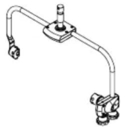
natural_image
Technical line drawing of a mechanical pipe fitting with two flanged ends and a central hub (no text or symbols)PIELEGNACJA, KONSERWACJA I NAPRAWA
Furthermore, this product is only intended for qualified users with specialist knowledge of event technology!
Il faretto ottempera lo standard RDM (Remote Device Management). This remote device management enables the status query and configuration of RDM end devices via an RDM-capable controller, such as the optionally available Cameo UNICON (item number CLIREMOTE).
| Control | Colour Coordinates | |
| DIM | x Coordinate | |
| 100% | 0.7346 | |
| Mode | Next Coordinate | Menu |
Ruota l'encoder =
| Edit USER_COLOUR_1 | ||
| Name | ||
| A B C D E F G H I J K L M N O P Q R S T U V W X Y Z _ 0 1 2 3 4 5 6 7 8 9 | ||
| Enter | Save&Next | ESC |
text_image
Edit LOOP_1 Name A B C D E F G H I J K L M N O P Q R S T U V W X Y Z _ 0 1 2 3 4 5 6 7 8 9 Enter Save&Next ESC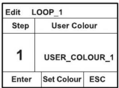
text_image
Edit LOOP_1 Step User Colour 1 USER_COLOUR_1 Enter Set Colour ESCnatural_image
Technical line drawing of a mechanical assembly with two views: one showing a bolted component inserted into a plate, the other showing a bracket with a handle and mounting feet (no text or symbols present)MONTAGGIO STATIVO

text_image
Technical diagram of a mechanical device with labeled parts A, B, and C, showing internal components like ventilation ducts and adjustment knobs.UTILIZZANDO I RACCORDI TV PER IL MONTAGGIO DELLA CAPRIATA

natural_image
Technical line drawing of a mechanical device with internal components and mounting features (no text or symbols)BRACCIALE OMEGA
natural_image
Technical diagram of a mechanical device with internal components and orange arrows indicating motion or flow (no text or symbols present)natural_image
Diagram of a mechanical component with an orange arrow indicating direction (no text or symbols)natural_image
Technical line drawing of a mechanical device with labeled component D (no text or symbols beyond label)
natural_image
Open black box with a white inner square, isolated on white background (no text or symbols)