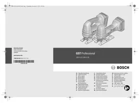
GST 85P - Jigsaw BOSCH - Free user manual and instructions
Find the device manual for free GST 85P BOSCH in PDF.

| Brand | Bosch |
| Model | GST 85P |
| Product type | Jigsaw |
| Rated power input | 580 W |
| Output power | 350 W |
| No-load stroke rate | 3100 spm |
| Stroke | 26 mm |
| Max. cutting depth in wood | 85 mm |
| Max. cutting depth in aluminium | 20 mm |
| Max. cutting depth in steel (non-alloy) | 10 mm |
| Max. bevel angle (left/right) | 45° |
| Weight (according to EPTA 01/2003) | 2.4 kg |
| Protection class | Double insulation |
| Pendulum action | 4 adjustable positions (0, I, II, III) |
| Blower device | 3 adjustable positions |
| Blade type | T-shank (T-stem) |
| Power supply | Mains, 230 V / 240 V |
| Sound pressure level | 83 dB(A) |
| Sound power level | 94 dB(A) |
| Vibration (sawing wood) | 5.5 m/s² (K=1.5 m/s²) |
| Vibration (sawing sheet metal) | 5.8 m/s² (K=1.5 m/s²) |
| Main functions | Straight and curved cuts, plunge cuts, mitre cuts up to 45°, parallel guide and circle guide (accessories) |
| Maintenance and cleaning | Regularly clean ventilation slots and blade holder; grease roller blade guide; check and replace if worn |
| Safety | Hand guard, emergency stop, double insulation, blade lock |
| Spare parts and repairability | Bosch after-sales service, spare parts available, repair by authorized stations |
| General information | Manual available in multiple languages; weight 2.4 kg; cable length not specified |
Frequently Asked Questions - GST 85P BOSCH
User questions about GST 85P BOSCH
0 question about this device. Answer the ones you know or ask your own.
Ask a new question about this device
Download the instructions for your Jigsaw in PDF format for free! Find your manual GST 85P - BOSCH and take your electronic device back in hand. On this page are published all the documents necessary for the use of your device. GST 85P by BOSCH.
USER MANUAL GST 85P BOSCH
Dr. Egbert Schneider
Dr. Eckerhard Ströttgen
Senior Vice President
Head of Product
Engineering
Certification


02.04.2008, Robert Bosch GmbH, Power Tools Division D-70745 Leinfelden-Echterdingen
Montage
General Power Tool SafetyWarnings
AWARNING
Read all safety warnings and all instructions. Failure to follow the
warnings and instructions may result in electric shock, fire and/or serious injury.
Save all warnings and instructions for future reference.
The term "power tool" in the warnings refers to your mains-operated (corded) power tool or battery-operated (cordless) power tool.
1) Work area safety
a) Keep work area clean and well lit. Cluttered or dark areas invite accidents.
b) Do not operate power tools in explosive atmospheres, such as in the presence of flammable liquids, gases or dust. Power tools create sparks which may ignite the dust or fumes.
c) Keep children and bystanders away while operating a power tool. Distractions can cause you to lose control.
2) Electrical safety
a) Power tool plugs must match the outlet. Never modify the plug in any way. Do not use any adapter plugs with earthed (grounded) power tools. Unmodified plugs and matching outlets will reduce risk of electric shock.
b) Avoid body contact with earthed or grounded surfaces, such as pipes, radiators, ranges and refrigerators. There is an increased risk of electric shock if your body is earthed or grounded.
c) Do not expose power tools to rain or wet conditions. Water entering a power tool will increase the risk of electric shock.
d) Do not abuse the cord. Never use the cord for carrying, pulling or unplugging the power tool. Keep cord away from heat, oil, sharp edges and moving parts. Damaged or entangled cords increase the risk of electric shock.
e) When operating a power tool outdoors, use an extension cord suitable for outdoor use. Use of a cord suitable for outdoor use reduces the risk of electric shock.
f) If operating a power tool in a damp location is unavoidable, use a residual current device (RCD) protected supply. Use of an RCD reduces the risk of electric shock.
3) Personal safety
a) Stay alert, watch what you are doing and use common sense when operating a power tool. Do not use a power tool while you are tired or under the influence of drugs, alcohol or medication. A moment of inattention while operating power tools may result in serious personal injury.
b) Use personal protective equipment. Always wear eye protection. Protective equipment such as dust mask, non-skid safety shoes, hard hat, or hearing protection used for appropriate conditions will reduce personal injuries.
c) Prevent unintentional starting. Ensure the switch is in the off-position before connecting to power source and/or battery pack, picking up or carrying the tool. Carrying power tools with your finger on the switch or energising power tools that have the switch on invites accidents.
d) Remove any adjusting key or wrench before turning the power tool on. A wrench or a key left attached to a rotating part of the power tool may result in personal injury.
e) Do not overreach. Keep proper footing and balance at all times. This enables better control of the power tool in unexpected situations.
f) Dress properly. Do not wear loose clothing or jewellery. Keep your hair, clothing and gloves away from moving parts. Loose clothes, jewellery or long hair can be caught in moving parts.
g) If devices are provided for the connection of dust extraction and collection facilities, ensure these are connected and properly used. Use of dust collection can reduce dust-related hazards.
16 | English
4) Power tool use and care
a) Do not force the power tool. Use the correct power tool for your application. The correct power tool will do the job better and safer at the rate for which it was designed.
b) Do not use the power tool if the switch does not turn it on and off. Any power tool that cannot be controlled with the switch is dangerous and must be repaired.
c) Disconnect the plug from the power source and/or the battery pack from the power tool before making any adjustments, changing accessories, or storing power tools. Such preventive safety measures reduce the risk of starting the power tool accidentally.
d) Store idle power tools out of the reach of children and do not allow persons unfamiliar with the power tool or these instructions to operate the power tool. Power tools are dangerous in the hands of untrained users.
e) Maintain power tools. Check for misalignment or binding of moving parts, breakage of parts and any other condition that may affect the power tool's operation. If damaged, have the power tool repaired before use. Many accidents are caused by poorly maintained power tools.
f) Keep cutting tools sharp and clean. Properly maintained cutting tools with sharp cutting edges are less likely to bind and are easier to control.
g) Use the power tool, accessories and tool bits etc. in accordance with these instructions, taking into account the working conditions and the work to be performed. Use of the power tool for operations different from those intended could result in a hazardous situation.
5) Service
a) Have your power tool serviced by a qualified repair person using only identical replacement parts. This will ensure that the safety of the power tool is maintained.
Machine-specific SafetyWarnings
- Keep hands away from the sawing range. Do not reach under the workpiece. Contact with the saw blade can lead to injuries.
Apply the machine to the workpiece only when switched on. Otherwise there is danger of kickback when the cutting tool jams in the workpiece.
Pay attention that the base plate 7 rests securely on the material while sawing. A jammed saw blade can break or lead to kickback. - When the cut is completed, switch off the machine and then pull the saw blade out of the cut only after it has come to a standstill. In this manner you can avoid kickback and can place down the machine securely.
Use only sharp, flawless saw blades. Bent or unsharp saw blades can break or cause kickback.
Do not brake the saw blade to a stop by applying side pressure after switching off. The saw blade can be damaged, break or cause kickback. - Use suitable detectors to determine if utility lines are hidden in the work area or call the local utility company for assistance. Contact with electric lines can lead to fire and electric shock. Damaging a gas line can lead to explosion. Penetrating a water line causes property damage or may cause an electric shock.
Hold the power tool only by the insulated gripping surfaces when performing an operation where the cutting tool may contact hidden wiring or its own cord. Contact with a "live" wire will also make exposed metal parts of the power tool "live" and shock the operator. - Secure the workpiece. A workpiece clamped with clamping devices or in a vice is held more secure than by hand.
- Keep your workplace clean. Blends of materials are particularly dangerous. Dust from light alloys can burn or explode.
Always wait until the machine has come to a complete stop before placing it down. The tool insert can jam and lead to loss of control over the power tool.
English | 17
- Never use the machine with a damaged cable. Do not touch the damaged cable and pull the mains plug when the cable is damaged while working. Damaged cables increase the risk of an electric shock.
Functional Description

Read all safety warnings and all instructions. Failure to follow the warnings and instructions may result in electric shock, fire and/or serious injury.
While reading the operating instructions, unfold the graphics page for the machine and leave it open.
Intended Use
The machine is intended for making separating cuts and cut-outs in wood, plastic, metal, ceramic plates and rubber while resting firmly on the workpiece. It is suitable for straight and curved cuts with metre angles to 45^ . The saw blade recommendations are to be observed.
Product Features
The numbering of the product features refers to the illustration of the machine on the graphics page.
1 Rotatable top handle with pushbutton
2 Thumbwheel for stroke rate preselection (GST 85 PE)
3 Allen key
4 On/Off switch
5 Switch for sawdust blowing device
6 Adjusting lever for orbital action
7 Base plate
8 Guide roller
9 Saw blade*
10 Contact protector
11 Stroke rod
12 Splinter guard
13 Scale for metre angle
14 Screw
15 Angle gauge*
16 Bolt hole
17 Positioning pin/mark
18 Lead for the parallel guide
19 Locking screw for parallel guide
20 Parallel guide with circle cutter
21 Centring tip of the parallel guide*
The accessories illustrated or described are not included as standard delivery.
*Commercially available (not included in the delivery scope)
Noise/Vibration Information
Measured values determined according to EN 60745.
Typically the A-weighted noise levels of the product are: Sound pressure level 83 dB(A); Sound power level 94 dB(A). Uncertainty K = 3 dB.
Wear hearing protection!
Vibration total values (triax vector sum) determined according to EN 60745:
Cutting wood: Vibration emission value a_h = 5.5 m/s^2 , uncertainty K = 1.5 m/s^2
Cutting sheet metal: Vibration emission value a_h = 5.8 m/s^2 , uncertainty K = 1.5 m/s^2 .
The vibration emission level given in this information sheet has been measured in accordance with a standardised test given in EN 60745 and may be used to compare one tool with another. It may be used for a preliminary assessment of exposure.
The declared vibration emission level represents the main applications of the tool. However if the tool is used for different applications, with different accessories or poorly maintained, the vibration emission may differ. This may significantly increase the exposure level over the total working period.
An estimation of the level of exposure to vibration should also take into account the times when the tool is switched off or when it is running but not actually doing the job. This may significantly reduce the exposure level over the total working period.
Identify additional safety measures to protect the operator from the effects of vibration such as: maintain the tool and the accessories, keep the hands warm, organisation of work patterns.
18 | English
Technical Data
| Jigsaw | GST 85 P Professional | GST 85 PE Professional | |
| Article number | 0 601 584 1.. | 0 601 584 6.. | |
| Stroke rate control | - | ● | |
| Rated power input | W | 580 | 580 |
| Output power | W | 350 | 350 |
| Stroke rate at no load n0 | spm | 3100 | 500–3100 |
| Stroke | mm | 26 | 26 |
| Cutting capacity, max. | |||
| - in wood | mm | 85 | 85 |
| - in aluminium | mm | 20 | 20 |
| - in non-alloy steel | mm | 10 | 10 |
| Bevel cuts (left/right), max. | ° | 45 | 45 |
| Weight according to EPTA-Procedure 01/2003 | kg | 2.4 | 2.4 |
| Protection class | ☐ / II | ☐ / II |
The values given are valid for nominal voltages [U] of 230/240 V. For lower voltage and models for specific countries, these values can vary.
Please observe the article number on the type plate of your machine. The trade names of the individual machines may vary.
Declaration of Conformity C
We declare under our sole responsibility that the product described under "Technical Data" is in conformity with the following standards or standardization documents: EN 60745 according to the provisions of the directives 2004/108/EC, 98/37/EC (until Dec. 28, 2009), 2006/42/EC (from Dec. 29, 2009 on).
Technical file at: Robert Bosch GmbH, PT/ESC, D-70745 Leinfelden-Echterdingen
Dr. Egbert Schneider
Dr. Eckerhard Strötgen
Senior Vice President
Head of Product
Engineering
Certification
Before any work on the machine itself, pull the mains plug.
- When mounting the saw blade, wear protective gloves. Danger of injury when touching the saw blade.
Selecting a Saw Blade
An overview of recommended saw blades can be found at the end of these instructions. Use only T-shank saw blades. The saw blade should not be longer than required for the intended cut.
Use a thin saw blade for narrow curve cuts.
Inserting the Saw Blade (see figure A)
Before inserting the saw blade 9, set the adjusting lever for orbital action 6 to setting III.
-
Press the orange pushbutton in the rotatable top handle 1 down until it can be felt to engage.
-
Turn the rotating handle 1 approx. three turns in the direction of the arrow.
- Insert the saw blade 9 lateral to the cutting direction into the stroke rod 11.
- Turn the saw blade 9 so that the tooting faces toward the cutting direction. Pull the saw blade 9 a little downward until it engages.
- Turn the rotating handle 1 in the direction of the arrow until a click can be heard.
- Push up the orange pushbutton at the rotatable top handle 1 again to the starting position.
Check the tight seating of the saw blade. A loose saw blade can fall out and lead to injuries.
Splinter Guard (see figure B)
Before any work on the machine itself, pull the mains plug.
The splinter guard 12 (accessory) can prevent fraying of the surface while sawing wood. The splinter guard can only be used for certain saw blade types and only for cutting angles of 0^ . When sawing with the splinter guard, the base plate 7 must not be moved back for cuts that are close to the edge.
Press the splinter guard 12 from the bottom into the base plate 7.
Dust/Chip Extraction
Dusts from materials such as lead-containing coatings, some wood types, minerals and metal can be harmful to one's health. Touching or breathing-in the dusts can cause allergic reactions and/or lead to respiratory infections of the user or bystanders.
Certain dusts, such as oak or beech dust, are considered as carcinogenic, especially in connection with wood-treatment additives (chromate, wood preservative). Materials containing asbestos may only be worked by specialists.
- Provide for good ventilation of the working place.
- It is recommended to wear a P2 filter-class respirator.
Observe the relevant regulations in your country for the materials to be worked.
Operation
Operating Modes
Before any work on the machine itself, pull the mains plug.
Orbital Action Settings
The four orbital action settings allow for optimal adaptation of cutting speed, cutting capacity and cutting pattern to the material being sawed.
The orbital action can be adjusted with the adjusting lever 6, even during operation.
Setting 0 No orbital action
Setting I Small orbital action
Setting II Medium orbital action
Setting III Large orbital action
The optimal orbital action setting for the respective application can be determined through practical testing. The following recommendations apply:
- Select a lower orbital action setting (or switch it off) for a finer and cleaner cutting edge.
- For thin materials such as sheet metal, switch the orbital action off.
- For hard materials such as steel, work with low orbital action.
- For soft materials and when sawing in the direction of the grain, work with maximum orbital action.
Adjusting the Cutting Angle (see figure C)
The base plate 7 can be swivelled by 45^ to the left or right for litre cuts.
- Loosen the screw 14 and lightly slide the base plate 7 in the direction of the saw blade 9.
- For adjustment of precise litre angles, the base plate has adjustment notches on the left and right at 0^ and 45^ . Swivel the base plate 7 to the desired position according to the scale 13. Other litre angles can be adjusted using a protractor.
- Afterwards, push the base plate 7 to the stop toward the mains cable.
- Tighten the screw 14 again.
The splinter guard 12 can not be inserted for mi- tre cuts.

20 | English
Offsetting the Base Plate (see figure D)
For sawing close to edges, the base plate 7 can be offset to the rear.
- Completely unscrew the screw 14 using the Allen key 3.
Take the base plate 7 off and remount it offset again so that the screw 14 can be screwed in to the rear bolt hole 16. - Push the base plate 7 toward the positioning pin/mark 17 until it engages. Now, tighten the screw 14 again.
Sawing with the base plate 7 offset is possible only with a litre angle of 0^ . In addition, the parallel guide with circle cutter 20 (accessory) as well as the splinter guard 12 may not be used.
Sawdust Blower Device
With the air jet of the sawdust blower device 5, the cutting line can be kept free of dust and chips.

Sawdust-blower setting I:
Low blow effect for sawing in metal and operation with coolant/lubricant.

Sawdust-blower setting II:
Medium blow effect for sawing materials with low chip removal rate, e. g., hardwood.

Sawdust-blower setting III:
Large blow effect for sawing materials with high chip removal rate, e.g., softwood, plastic, etc.
Contact Protector
The contact protector 10 attached to the casing prevents accidental touching of the saw blade during the working procedure and may not be removed.
Starting Operation
Observe correct mains voltage! The voltage of the power source must agree with the voltage specified on the nameplate of the machine. Power tools marked with 230V can also be operated with 220V .
Switching On and Off
To start the power tool, push the On/Off switch 4 forwards.
To switch off the machine, push the On/Off switch 4 toward the rear.
Presetting the Stroke Rate (GST 85 PE)
With the thumbwheel for stroke rate preselection 2, the stroke rate can be preset and changed during operation.
1-2: Low stroke rate
3-4: Medium stroke rate
5-6: High stroke rate
The required stroke rate is dependent on the material and the working conditions and can be determined by a practical trial.
Reducing the stroke rate is recommended when the saw blade engages in the material as well as when sawing plastic and aluminium.
After longer periods of work at low stroke rate, the machine can heat up considerably. Remove the saw blade from the machine and allow the machine to cool down by running it for approx. 3 minutes at maximum stroke rate.
Working Advice
- When working small or thin work pieces, always use a sturdy support or a saw table (accessory).
Check wood, press boards, building materials, etc. for foreign objects such as nails, screws or similar, and remove them, if required.
Plunge Cutting (see figure E)
The plunge cutting procedure is only suitable for treating soft materials such as wood, plaster board or similar! Do not work metal materials with the plunge cutting procedure!
Use only short saw blades for plunge cutting. Plunge cutting is possible only with the metre angle set at 0^ .
English | 21
Place the machine with the front edge of the base plate 7 on to the workpiece without the saw blade 9 touching the workpiece and switch on. For machines with stroke rate control, select the maximum stroke rate. Firmly hold the machine against the workpiece and by tilting the machine, slowly plunge the saw blade into the workpiece. When the base plate 7 fully lays on the workpiece, continue sawing along the desired cutting line.
Parallel Guide with Circle Cutter (Accessory)
For cuts using the parallel guide with circle cutter 20 (accessory), the thickness of the material must not exceed a maximum of 30~mm .
Parallel Cuts (see figure F): Loosen the locking screw 19 and slide the scale of the parallel guide through the lead 18 in the base plate. Set the desired cutting width as the scale value on the inside edge of the base plate. Tighten the locking screw 19.
Circular Cuts (see figure G): Set the locking screw 19 to the other side of the parallel guide. Slide the scale of the parallel guide through the lead 18 in the base plate. Drill a hole in the workpiece centred in the section to be sawn. Insert the centring tip 21 through the inside opening of the parallel guide and into the drilled hole. Set the radius as the scale value on the inside edge of the base plate. Tighten the locking screw 19.
Dismounting the Rotatable Top Handle
Before any work on the machine itself, pull the mains plug.
For easier sawing in particularly tight locations, the rotatable top handle 1 can be dismounted. For this, press the orange pushbutton beyond the latching point and pull off the rotatable top handle upward at the same time.
Before assembling the rotatable top handle 1, push up the orange pushbutton back into the starting position again. Attach the rotatable top handle 1 and press downward until it can be felt to engage.
Coolant/Lubricant
When sawing metal, coolant/lubricant should be applied alongside cutting line because of the material heating up.
Maintenance and Service
Maintenance and Cleaning
Before any work on the machine itself, pull the mains plug.
For safe and proper working, always keep the machine and ventilation slots clean.
Clean the saw blade holder regularly. For this, remove the saw blade from the machine and lightly tap out the machine on a level surface.
Heavy contamination of the machine can lead to malfunctions. Therefore, do not saw materials that produce a lot of dust from below or overhead.
In extreme working conditions, conductive dust can accumulate in the interior of the machine when working with metal. The protective insulation of the machine can be degraded. The use of a stationary extraction system is recommended in such cases as well as frequently blowing out the ventilation slots and installing a residual current device (RCD).
Lubricate the guide roller 8 occasionally with a drop of oil.
Check the guide roller 8 regularly. If worn, it must be replaced through an authorised Bosch after-sales service agent.
If the machine should fail despite the care taken in manufacturing and testing procedures, repair should be carried out by an after-sales service centre for Bosch power tools.
In all correspondence and spare parts order, please always include the 10-digit article number given on the type plate of the machine.
22 | English
WARNING! Important instructions for connecting a new 3-pin plug to the 2-wire cable.
The wires in the cable are coloured according to the following code:

Do not connect the blue or brown wire to the earth terminal of the plug.
Important: If for any reason the moulded plug is removed from the cable of this power tool, it must be disposed of safely.
After-sales Service and Customer Assistance
Our after-sales service responds to your questions concerning maintenance and repair of your product as well as spare parts. Exploded views and information on spare parts can also be found under:
www.bosch-pt.com
Our customer consultants answer your questions concerning best buy, application and adjustment of products and accessories.
Great Britain
Robert Bosch Ltd. (B.S.C.)
P.O.Box 98
Broadwater Park
North Orbital Road
Denham
Uxbridge
UB95HJ
Tel. Service: +44 (0844) 736 0109
Fax: +44 (0844) 736 0146
Australia, New Zealand and Pacific Islands
Robert Bosch Australia Pty. Ltd.
Power Tools
Locked Bag 66
Clayton South VIC 3169
Customer Contact Center
Inside Australia:
Phone: +61 (01300) 307 044
Fax: +61 (01300) 307 045
Inside New Zealand:
Phone: +64 (0800) 543 353
Fax: +64 (0800) 428 570
Outside AU and NZ:
Phone: +61 (03) 9541 5555
www.bosch.com.au
Disposal
The machine, accessories and packaging should be sorted for environmental-friendly recycling.
Only for EC countries:
Do not dispose of power tools into household waste! According the European Guideline 2002/96/EC for Waste Electrical and Electronic Equipment and its implementation into national right,
power tools that are no longer usable must be collected separately and disposed of in an environmentally correct manner.
Subject to change without notice.

Français 23
Dr. Egbert Schneider
Dr. Eckerhard Strötgen
Senior Vice President
Head of Product
Engineering
Certification
ppa. Maee i.v. Nogcu
02.04.2008, Robert Bosch GmbH, Power Tools Division D-70745 Leinfelden-Echterdingen
Montage
Robert Bosch (France) S.A.S.
Senior Vice President
Engineering
Dr. Eckerhard Strötgen
Head of Product
Certification

02.04.2008, Robert Bosch GmbH, Power Tools Division D-70745 Leinfelden-Echterdingen
Montaje
Senior Vice President
Engineering
Dr. Eckerhard Strötgen
Head of Product
Certification

02.04.2008, Robert Bosch GmbH, Power Tools Division D-70745 Leinfelden-Echterdingen
Montagem
Dr. Egbert Schneider Senior Vice President Engineering
Dr. Eckerhard Strötgen
Head of Product
Certification
ppa. Maee i.v. Nogc
02.04.2008, Robert Bosch GmbH, Power Tools Division
D-70745 Leinfelden-Echterdingen
Montaggio
Dr. Egbert Schneider
Dr. Eckerhard Ströttgen
Senior Vice President
Head of Product
Engineering
Certification
ppa. Maee i.v. Nogcu
02.04.2008, Robert Bosch GmbH, Power Tools Division D-70745 Leinfelden-Echterdingen
Montage
Zaagblad inzetten of verrangen
Dr. Egbert Schneider Senior Vice President Engineering
Dr. Eckerhard Strötgen
Head of Product Certification


02.04.2008, Robert Bosch GmbH, Power Tools Division D-70745 Leinfelden-Echterdingen
Montering
Bosch Service Center
Telegrafvej 3
2750 Ballerup
Tel. Service Center: +45 (04489) 8855
Fax: +45 (04489) 87 55
E-Mail: vaerktoej@dk.bosch.com
Bortskaffelse
Dr. Egbert Schneider Senior Vice President Engineering
Dr. Eckerhard Ströttgen
Head of Product Certification

02.04.2008, Robert Bosch GmbH, Power Tools Division D-70745 Leinfelden-Echterdingen
Montage
Dr. Egbert Schneider Senior Vice President Engineering
Dr. Eckerhard Ströttgen
Head of Product Certification


02.04.2008, Robert Bosch GmbH, Power Tools Division D-70745 Leinfelden-Echterdingen
Bosch Power Tools
1609929N90|(8.4.08)
88 | Norsk
Montering
Dr. Egbert Schneider
Dr. Eckerhard Ströttgen
Senior Vice President
Head of Product
Engineering
Certification
ppa. Maee i.v. Nogcu
02.04.2008, Robert Bosch GmbH, Power Tools Division D-70745 Leinfelden-Echterdingen
Asennus
Dr. Egbert Schneider
Dr. Eckerhard Ströttgen
Senior Vice President
Head of Product
Engineering
Certification

02.04.2008, Robert Bosch GmbH, Power Tools Division D-70745 Leinfelden-Echterdingen
Συναρμολόγηση
SuvapmoIoyon/AvtikataoTnC npioVoaamc
BydceTeTo iacnoTnV npicipiv ano onoi- 6hntote epyaia oTo nAekptko epyaleio.
ΦopéoTe npoOtaeutká yáVtia yia va ouvapmooynoe TnV npovolapa. YnApxei kivduoc Tpaumatioou av ayyiete Tnv npovolapa.
Enuoyn nnc npiovoaapac
TToTeLoacutwvTwovObnyiwXeiipiaouOaβpeite
mu eniokonnanTwv npoteivoevw npiovoalaow.
Xpoaiomoiite mvo npiovolauec me otelexoc
ekkvetpwv (oteloxoc oopnC T).Na xpoaiomoiie Te piovolauec nou dev evivaakpuTepec an'
oo npoBleIeTAYtNv avtoxn konn.
XpouoieTc Tevc npovolae c yia Tnv konn kaunwv.
Uvapuoloyon TnC npiovolaAaC (BLeNE eKoVA A)
Piv tonoetnae tny npiovola 9 eote to diakontn puthetaiounc taavtwong6 stn bathetaiida III.
- Pataote npoc ta kawto npotokaia nKtpo stnv nepiortpeoevn laβn 1 mexpi va akouoete otu avdeltaomega.
ΓupioTe Tny nepioppeoevn 1 nepinou Tpeic oTpopec onwocdeltaxve to o c
ToiooTeiote Tnv npiovola 9 ot npafoe Boiaou 11 eykapoiia wc npoc tn foopa koninC.
ΓupioTe TnV npiovola 9 eToi, oTe n odovtwan va deixvei npoc tn popa konnc. TpaBnEe TnV npiovola 9 liyo npoc ta kaTomega, mexoiv aavdaawoei.
ΓupioTe Tn nepiotpepóevn λaβn 1 onwC δeixvei to βeλoç, μexpi va akouoete eva «KλιΚ». - PataoTepocTa enaw, oTnv apxik Tou theon, to npotokai pAnktpo otnv nepiotpepoevni a 1
EeYTe,av n npiovolapa eXei ouvapmoyn- 0ei aopawc. Mia xaapn npiovola ma npopei va netaxtei eXw ka va oac tpaumatoei.
Ppoulaaktiko oKAnθpωv (βλeπε εικóva B)
Bydcte To oic ano ntv npica npiv ano onoi- 8hntote epyaia oTo nAektpikO epvaieio.
To npoataeutikok k 12 (eiidiko eapntma)
mopei va eumodioe to oxiau o nC enipaveiaoc
otav npiovicete Eluo. To npoataeutikok akln0wv
mopei va xnpoiopoinoie mvo yia
ouykepivec npovolacekai mvo yia wvie c
koinc 0^ .To neIa7 dev eniptepenetai, otav
npoiivee me npoataeutikok okln0pwv,va
metakivneipoc ta niow ia va npopoeote etoi
va npiovice t Kovta oto nepiowio.
PntnoTe TnpooTaTeutiko oKAnhOpoWv 12 ano To kAtw meoc yia va mne i eoa oTo nla7.
Avappoqn oKovnc/pokaviδιwv
H okovn ano opioeva uliká. n.x. ano moluβ- douxec mnoiyiec, ano empika eibn Eulou, ano opukta uliká kai ano metaλλa mnpoei va eivai avuyieivn. H enapn me tn okovn /kai n eiTnvon Tnc mnpoei va npokaloeoi aAlehpyikec avtbpaoei n/kai aohevieic twv avanveu- otikw obw vou xpnotn tuxov napepupoko- evww atoow.
Opioueva eioN oKovn, n.x. oKovn ano Eluo
Belaiaic n oxiac oewpuovtaa avkapivoyova, 1iaitepa oe ouvduaumo e diapopa
oumnpwata kuaik aou xpnaiopoiouovta
otnv katepyaia Eluaw (evwoecxpwuiou,
Eluonpoataeutika eaa). H katepyaia
aiavtouxw ulikw enitpenetai mvo ae
eiikak eknaiideupeva atota.
Dr. Egbert Schneider Senior Vice President Engineering
Dr. Eckerhard Strötgen
Head of Product Certification


02.04.2008, Robert Bosch GmbH, Power Tools Division D-70745 Leinfelden-Echterdingen
Montaj
Strok sayisi on seciimi (GST 85 PE)
Bosch San. ve Tic. A.S.
Ahi Evran Cad. No:1 Kat:22
Polaris Plaza
80670 Maslak/Istanbul
Müsteri Danismani: +90 (0212) 335 06 66
Müsteri Servis Hatti: +90 (0212) 335 07 52