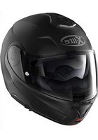
1005 - Motorcycle helmet X-Lite - Free user manual and instructions
Find the device manual for free 1005 X-Lite in PDF.


| Product type | Modular full-face motorcycle helmet |
| Brand | X-Lite |
| Model | 1005 |
| Shell material | Polycarbonate (LEXAN™) |
| Retention system | Double D-ring |
| Visor | XMS-02, scratch resistant, with Pinlock preparation |
| Sun visor | VPS-14, internal sun visor, anti-fog and scratch resistant |
| Anti-fog system | Pinlock® (standard or optional) |
| Chin guard opening | DUAL ACTION: two red levers (unlock then opening) |
| Ventilation | Lower (mouth and visor), upper (head), rear (hot air extraction) |
| Inner lining | Removable and washable, cheek pads can be removed |
| Liner adjustment system | LINER POSITIONING CONTROL (LPC) – 8 positions |
| Eyewear adaptation | EYEWEAR ADAPTIVE – pre-cut space in cheek pads |
| Wind deflector | Wind Protector (standard or optional) |
| Communication readiness | N-Com (depending on version) |
| Certification | ECE 22-05 |
| Cleaning | Warm water and neutral soap; dry away from sunlight |
| Visor maintenance | Do not use solvents, gasoline or thinners |
| Compatible accessories | Pinlock, VPS, N-Com, wind deflector |
Frequently Asked Questions - 1005 X-Lite
User questions about 1005 X-Lite
0 question about this device. Answer the ones you know or ask your own.
Ask a new question about this device
Download the instructions for your Motorcycle helmet in PDF format for free! Find your manual 1005 - X-Lite and take your electronic device back in hand. On this page are published all the documents necessary for the use of your device. 1005 by X-Lite.
USER MANUAL 1005 X-Lite
natural_image
Black and white photo of a Xlite helmet with reflective visor and headrest (no text or symbols on the helmet itself)
bar
| Category | Value | |---|---| | Category 1 | 100 | | Category 2 | 100 | | Category 3 | 100 | | Category 4 | 100 | | Category 5 | 100 | | Category 6 | 100 | | Category 7 | 100 | | Category 8 | 100 | | Category 9 | 100 | | Category 10 | 100 |
text_image
X-liteCONGRATULATIONS on the purchase of your new helmet.
This helmet has been designed and created to be a modern, high performing product, able to satisfy the most demanding requests as for safety and comfort. This is made possible by the helmet design, its ergonomic, comfort and aerodynamic properties as well as its practical and easy-to-use controls.
SAFETY AND INSTRUCTIONS FOR USE
IMPORTANT
Before using the helmet read this booklet and all enclosed documents carefully, in that they contain very important indications on how to use the helmet easily and safely. We recommend you to store it for future reference.
- Failure to observe these instructions may reduce the protection provided by the helmet and consequently put your safety at risk.
- Do not operate or act in such a way that could compromise or reduce the protection provided by the helmet.
USING THE HELMET
- The helmet is specifically designed for motorcycle and motorbike use. Therefore, it must not be used for different purposes (or different reasons or operations) since, in such cases, it would not guarantee the same protection.
- In case of accident, the helmet represents a protective element, which reduces injuries and head damage.
Nevertheless, no helmet can guarantee total safety. The helmet reduces the risk or gravity of injuries in case of accidents, but the degree of impacts and the different circumstances may exceed helmet protection. Therefore, ride safely. - When riding any motorcycle, always wear the helmet properly fastened in order to fully exploit its protection.
- Never wear scarves under the fastening system nor caps of any sort under the helmet.
- The helmet can muffle traffic noises. However make sure that you can hear essential sounds such as horns and emergency vehicle sirens.
- Always keep the helmet away from heat sources like the exhaust muffler, the bag seat or the interior of a vehicle.
- Do not modify nor tamper with the helmet (or part of it) for any reason whatsoever. Any modification and/or change compromise safety requirements and the protection degree of the helmet. The helmet may be no more compliant to homologation standards and therefore could not be used anymore, thus guarantee will be void.
- Use only original accessories and/or spare parts suitable for your specific helmet model.
- Damage resulting from accidental fall may not be visible, or not visible with the naked eye; helmets which received impacts are to be replaced. Always handle your helmet carefully in order not to compromise or reduce its protection degree.
- In case of doubt about the helmet integrity and safety, avoid using it and contact an authorized dealer to let it check.
CHOOSING THE HELMET
1SIZE
1.1 In order to determine the correct helmet size, try on helmets of different sizes and choose the one which suits best the shape of your head and which you feel firm once worn and fastened, thus ensuring a great comfort.
1.2 Should the helmet be too big, it may slide down covering the eyes or turn slowly to the side while riding.
1.3 Keep it on for a few minutes and make sure there are no points of extreme pressure that may cause pain or headache.
2TAKINGOFFTHEHELMET
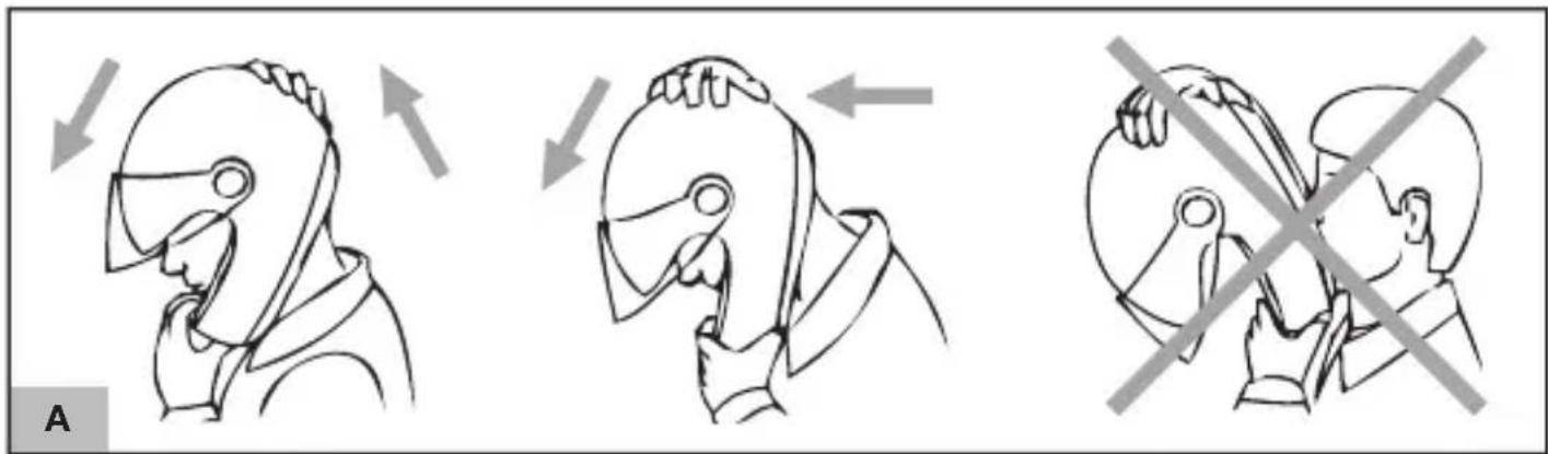
2.1 With the helmet on and the strap securely fastened, try to take the helmet off as shown in figure (A). In case of accident the different forces at stake and their various directions may result in helmet rotations or they may even cause the helmet to slip off if it is not securely fastened.
2.2 The helmet should not rotate nor move on the head and should not slide off. Should the contrary happen, adjust strap length or change helmet size. Repeat test.
3RETENTIONSYSTEM
3.1 The retention system (strap) is factory-adjusted at a standard length. Before use, check that it is correctly pre-adjusted.
3.2 Make sure the strap is properly fastened and tightened so as to keep the helmet firmly in place. Anyway, before riding, make sure that the strap is well fastened under the chin, as close as possible to the throat, but without being uncomfortable.
3.3 The correct strap tension should allow normal breathing and swallowing, but without leaving the space of a finger between strap and throat.
WARNING
The button which may be present on the strap only prevent its end from flapping once the strap has been fastened properly.
VISOR
- If the visor is damaged or deeply scratched causing reduced visibility, this means that the protective treatment is probably damaged so the visor is to be replaced.
- The visor can be used for the intended helmet model only.
- Do not paint nor apply stickers.
MAINTENANCE AND CLEANING
WARNING
Helmet and visor may be seriously damaged by some common substances without the damage being however visible. Use only lukewarm water and mild soap to clean helmet and visor, and then let them dry at room temperature away from sunrays and/or heat sources.
WARNING
Never use petrol, thinner, benzene, solvents nor other chemicals which may:
-Irreparablydamagethehelmet;
- Modify optical properties, reduce mechanical ones and weaken the visor protective treatment.
text_image
ADUAL ACTION
This unique chin guard opening system - positioned in the centre of the chin guard - allows for easy, one-handed opening and prevents it from accidentally opening. The chin guard can only be opened after operating the first red lever (release lever) and then the second red lever (opening lever).
The configuration with chin guard open and VPS raised is recommended to ensure a better fit of the helmet.
1 CHIN GUARD OPENING
1.1 Push the red release lever outwards by turning it with your thumb (Fig.1).
1.2 Place your forefinger on top of the opening lever and push it downwards to lock the chin guard (Fig.2).
1.3 Pull the chin guard forwards and then follow its rotation upwards (Fig.3).
If the helmet is used with chin guard open (J configuration), it is recommended that you place the left side locking slider in position "J" to secure the chin guard in lifted position (Fig.4B).
2 CHIN GUARD CLOSING
WARNING
When the left side locking slider is in position “J” do not force the closing of the chin guard because it could damage the helmet’s closing mechanism. Move the locking slider to position “P” (Fig.4A) to close the chin guard.
2.1 Pull the chin guard downwards, following its rotation, until you hear the closing mechanism clicking (Fig.3).
2.2 Make sure the chin guard is correctly fastened by pulling it forwards and by checking that both sides remain fastened to the shell.
When the left side locking slider is in position "P", the chin guard can be opened and/or closed (Fig.4A).
When the left side locking slider is in position “J”, the chin guard cannot be closed and remains blocked in open position (Fig.4B).
WARNING
- The protection level of this helmet whilst riding depends on the configuration adopted by the user: total protection if the chin guard and visor are closed, partial protection if the chin guard and/or visor are open.
- Do not remove nor tamper with the fixing screws that connect the chin guard to the shell.
- Do not use the helmet without chin guard.
- Never use the helmet in case of malfunctioning and/or damages of the chin guard opening system. In case of doubts regarding the correct operation of the chin guard opening mechanism, contact a Nolangroup authorized dealer.
VISOR (XMS-02)
1DISASSEMBLY
1.1 Close the chin guard (if open) and open the visor completely.
1.2 Push the release lever of the left side mechanism completely downwards (Fig.5) and simultaneously push the visor away from the helmet initially projecting the lower hook "A" and then the top hook "B" from the corresponding seats in the side mechanism (Fig.6).
1.3 Follow the previous operations on the right side of the helmet.
2ASSEMBLY
2.1 Close the chin guard (if open) and position the left side of the visor on the corresponding side mechanism by inserting the top hook "B" of the visor into the corresponding seat therein. Align the lower hook "A" of the visor above the corresponding seat in the same mechanism (Fig.6).
2.2 Press the visor at the lower hook "A" so that the release lever recedes and then returns to position, hooking the visor to the side mechanism with just a click (Fig.5).
2.3 Follow the previous operations on the right side of the helmet.
2.4 Close the visor completely.
▲WARNING
- Make sure that the mechanisms are working properly. Open the visor. By lifting the chin guard, the visor closes automatically. If necessary, repeat the same operations mentioned above.
- Make sure that the mechanisms are working properly. Open and close the visor, making sure the latter is held in place in its different positions by the mechanisms itself. If necessary, repeat the same operations mentioned above.
- Do not use the helmet if the visor has not been assembled properly.
- Do not remove the side mechanisms from the chin guard.
- Should any of the side mechanisms fail or be damaged, please contact a Nolan-group authorized dealer.
MINIMUM OPENING POSITION WITH DEFOGGING FUNCTION
The visor can be slightly opened, with no need to place it on the first notch of the mechanism. In this configuration, the inner central pawl of the visor leans onto a specific seat on the helmet chin guard that allows the visor to be kept in a minimum opening position for a better ventilation and making defogging easier, especially at low speed or during short stops.
PINLOCK
(Available as standard or accessory/spare part)
1ASSEMBLY
1.1 Disassemble the visor (see instructions above).
1.2 Make sure that the inner surface of the visor is clean and check that the pin adjustment external levers are turned inwards (Fig.7).
1.3 Place the PINLOCK ^® inner visor on the visor.
The silicone-sealed profile of the PINLOCK® inner visor must be in contact with the inner surface of the visor.
1.4 Insert one side of the PINLOCK ^® inner visor onto one of the two visor pins and hold it in position (Fig.8).
1.5 Widen the visor and fasten the other side of the PINLOCK® inner visor to the other pin (Fig.9).
1.6 Release the visor.
1.7 Peel the protective film off the PINLOCK inner visor and check that its silicone-sealed profile adheres to the whole visor.
1.8 Fit the visor on the helmet (see instructions above).
2 CHECKING AND ADJUSTING THE STRETCH
Check that the PINLOCK ^® inner visor has been correctly fitted by opening and closing the visor and ensuring that they do not move with respect to each other.
If the PINLOCK ^® inner visor is not tightly fixed to the visor, simultaneously move both external adjustment levers upwards to increase the stretch (Fig.7). This operation must be carried out gradually. The maximum stretch is achieved when the pin adjustment external levers are turned outwards.
WARNING
- Dust between the two visors may cause both surfaces to scratch.
-ScratchedPINLOCK ^® visors and inner visors may cause reduced visibility and must therefore be replaced. - Regularly check the correct stretch of the PINLOCK ^® inner visor to prevent it from moving and scratching both surfaces.
- If the helmet visor fogs up and/or condensation forms between the visors, check that the PINLOCK® inner visor is both correctly fitted and stretched.
- An excessive and early stretch of the PINLOCK ^® inner visor may result in excessive adherence against the visor surface and/or permanent deformations with subsequent inability to correctly perform any following adjustments.
- Intense sweating/breathing, use in particular weather conditions (low temperatures, high humidity, sudden changes in temperature or heavy rain) or intense and prolonged use may affect the performance of the PINLOCK® inner visor and cause fogging or formation of condensation. In such cases, to restore the system efficiency after using the helmet, remove the PINLOCK® inner visor from the helmet visor and leave it to dry in warm and dry air. The same procedure must be applied to the helmet, which should be left to dry to remove any humidity that may have formed as a result of the conditions described above.
3 DISASSEMBLING THE PINLOCK ® INNER VISOR
3.1 DISASSEMBLE THE VISOR EQUIPPED WITH the PINLOCK® inner visor (see instructions above).
3.2 Widen the visor and release the PINLOCK® inner visor from the pins (Fig.9).
3.3 Release the visor.
4 MAINTENANCE AND CLEANING
- Remove the PINLOCK ^® inner visor from the visor. Using a damp and soft cloth, gently clean it with mild liquid soap. Rinse off all the soap under running water.
- Leave the visor to dry in warm and dry air without wiping it.
- To preserve the visor's condition over time, leave the helmet to dry in a ventilated and dry place with the visor open after use. Keep it away from heat sources and store it in a place away from direct light.
- Do not use solvents or chemical products.
VISION PROTECTION SYSTEM (VPS) - (VPS-14)
The exclusive inner VISION PROTECTION SYSTEM (VPS) is a LEXAN™ (*) polycarbonate moulded sunscreen with scratch-resistant/fog-resistant treatment. It is very simple and practical to use: just lower it to activate it or lift it to remove it from your field of vision. It is useful in all sorts of situations, both on long journeys out of town and shorter town trips. Moreover, the fastening system allows you to assemble and disassemble the sunscreen for ordinary maintenance and cleaning, using no tools.
1OPERATION
The VPS mechanism allows to activate the sunscreen by simply lowering it until the visor field of vision is partially covered. In this way, the light transmittance is reduced as desired. At any time, without operating the visor, the VPS can be deactivated with a simple movement and easily lifted up to restore the normal conditions of visibility and protection guaranteed by the approved helmet visor.
1.1 To activate the VPS, move the slider as in Fig.10 until you hear a click that means that the VPS is in the desired position.
The VPS is adjustable in a range of intermediate positions to ensure the best comfort for the user with respect to the terms of use.
1.2 To deactivate the VPS, press the recovery button as shown in Fig.11 until the VPS unlocks and moves automatically in standby position.
2 PRECAUTIONS FOR USE
The current approval standards (ECE 22-05) state that the visor minimum light transmittance levels must be greater than 80% when riding at night and not less than 50% when riding in daylight. For this reason, under particularly bright weather conditions, e.g. very strong sunlight caused by high intensity and/or incidence of the sunbeams, the use of sunglasses - which entail a transmittance much lower than 50% - is recommended or even necessary. This way, eye fatigue on long trips is reduced as well as the risk of direct dazzling, as opposed to the use of mere approved helmet visors. However, the use of sunglasses makes it difficult to perform emergency manoeuvres when the maximum visibility range of the helmet visor must be quickly restored. Just think, for example, of what happens when you enter a tunnel or when unexpected changes in environmental brightness occur. Thanks to its operating mechanism, the VPS makes these operations much easier.
WARNING
- Use the special slider to activate/deactivate the VPS; do not deactivate the VPS by handling it directly.
- The VPS can only be used during the day and under the environmental conditions described before.
- At night and/or in conditions of poor visibility, the VPS must be deactivated.
- Always ensure that the VPS is properly positioned according to different weather and environmental conditions and/or recommendations for use outlined above.
- We recommend your using of the VPS only and solely together with the approved standard visor, which has a transmittance value greater than 80%.
- The VPS does not replace the protection guaranteed by the visor.
- Always make sure that the VPS is clean and that it is operating properly in order to avoid scratches and/or anomalous wear on it every time it is activated.
- As for VPS and visor maintenance and cleaning operations, please refer to the appropriate section in the helmet user's manual.
- The VPS scratch resistant/fog-resistant treatment highly reduces fogging. Protracted periods of adverse weather and/or environmental conditions might cause fogging and/or formation of condensation on the VPS, which entails a reduction of visibility and/or sharpness of vision: in this case, deactivate the VPS.
- In case of rain, the direct contact of raindrops with the scratch resistant/fog-resistant treated VPS quickly reduces sharpness of vision, thus causing scarce visibility: in this case, deactivate the VPS.
- The special VPS fog-resistant treatment is usually sensitive to high temperatures or heat sources. In this case, contaminations caused by contact with other materials might occur. These contaminations will cause marks and stains to come out. In these cases (e.g. when the helmet is kept in the top case on hot days), it is recommended that the VPS does not come into contact with other materials.
3DISASSEMBLY
3.1 Open the helmet chin guard and lower the VPS completely (see instructions above).
3.2 Hold the left lateral part of the sunscreen and pull it toward the outside of the helmet (Fig. 12).
3.3 Repeat the same operation on the right side of the helmet.
4ASSEMBLY
4.1 Open the helmet chin guard and move the side slider until it stops (see instructions above) (Fig. 10).
4.2 Insert the sunscreen left end into the left side guide until it is hooked in the shell seat (Fig. 12).
4.3 Repeat the same operation on the right side of the helmet.
▲WARNING
- Make sure the VPS operates correctly by activating and deactivating it (see instructions above). If necessary, repeat the same operations mentioned above.
- If the VPS opening and closing mechanisms are not working properly or if such mechanisms get damaged, please contact a Nolangroup authorized dealer.
- Do not use the helmet if the VPS has not been assembled properly.
- Since the VPS does not assure you the same protection as the one provided by the visor, it has to be used only when the helmet visor is lowered.
REMOVABLE INNER COMFORT PADDING
The removable comfort padding consists of:
- a liner
- side cheek pads (right and left)
All components can be completely removed and washed.
The cheek pads are also characterised by removable inner expanding foam padding. Deactivate the VPS and lift the helmet chin guard to remove and/or install the comfort padding (see instructions above).
1 DISASSEMBLING THE CHEEK PADS
1.1 Open the chin strap (see specific instructions) and remove the chin strap band from the elastic loop on the cheek pad strap (Fig.13).
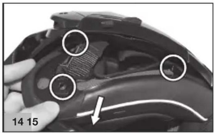
1.2 Pull the front of the left cheek pad towards the inside of the helmet to release the three buttons on its back (Fig. 14)
1.3 Remove the rear flap of the comfort padding of the left cheek pad from the cavity between the rear trim and the polystyrene inner shell. Then completely remove the cheek padding from the helmet (Fig.15).
1.4 Repeat these steps with the padding of the right cheek pad.
Do not remove the polystyrene cheek pads from the helmet shell.
2 DISASSEMBLING THE INNER EXPANDING FOAM PADDING OF THE CHEEK PADS
To facilitate the washing of the inner comfort padding components, the cheek pads of the helmet are fitted with inner expanding foam padding that can be removed from the fabric lining. To remove the padding, proceed as follows after disassembling the cheek pads from the helmet (see instructions above).
2.1 Unhook the three eyelets "A" of the rear frame of the left cheek pad slot next to the two snap buttons (front and rear) on the back (Fig.16).
2.2 Carefully remove the inner expanding foam padding from the fabric lining of the left cheek pad (Fig.17).
2.3 Repeat these steps with the padding of the right cheek pad.
Warning: once the inner paddings made of expanding foam have been removed from the cheek pads, ensure that rear “B”, front “A” and rear “A” snap buttons are correctly hooked to the rear frame of the fabric lining of the cheek pads (Fig.18). Otherwise, position them again appropriately.
3 DISASSEMBLING THE LINER
3.1 Pull the front part of the comfort padding towards the inside of the helmet, at the relevant central puller, to release the left and right rear tabs on the liner from the rear edge of the shell (Fig. 19).
3.2 Remove the adjustment flap from the rear cavity between the outer shell and the polystyrene inner shell.
3.3 Pull the back of the comfort padding towards the inside of the helmet to release the two side buttons located at the back from their seats on the rear support, which is fixed to the polystyrene inner shell (Fig.20).
3.4 Hold the left front part of the liner and pull it upwards in order to remove the corresponding liner flap from the support fixed to the polystyrene inner shell (Fig.21). Then repeat the operation with the central front flap and with right flap.
3.5 Completely remove the comfort padding from the helmet.
4 ASSEMBLING THE LINER
4.1 Insert the liner correctly into the helmet and have it well fitted against the base.
4.2 Insert the central front flap of the liner into its seat on the support fixed to the polystyrene inner shell and push it downwards until it is completely locked (Fig.21). Then repeat the operation with the left and right flaps making sure that the side ends of the liner are placed between the external side frames and the polystyrene inner shell.
Warning: Check the correct assembly of the liner front area by lifting and lowering the VPS. These movements should be smooth. If this is not the case, repeat steps 3.4 and 4.2.
4.3 Fasten the two side buttons on the back of the rear part of the comfort padding to the corresponding seats on the rear support fixed to the polystyrene inner shell (Fig.20).
4.4 Insert the adjustment flap of the liner into the rear cavity between the outer shell and the polystyrene inner shell.
4.5 Insert the rear right and left flaps of the liner into the corresponding seats of the shell edge (Fig.19). Push the flaps until they are fully hooked onto the support.
5 ASSEMBLING THE INNER EXPANDING FOAM PADDING OF THE CHEEK PADS
5.1 Gently put the inner expanding foam padding inside the fabric lining of the left cheek pad (Fig.17). Carefully spread out the padding while checking that there are no creases in the cheek pad fabric lining.
5.2 Unhook the two eyelets "A" of the rear frame of the left cheek pad slot next to the two snap buttons (front and rear) on the back (Fig.16).
5.3 Repeat these steps with the padding of the right cheek pad.
6 ASSEMBLING THE CHEEK PADS
WARNING
take the left cheek pad and ensure that rear “B”, front “A” and rear “A” snap buttons are correctly hooked to the rear frame of the fabric lining of the cheek pads (Fig.16). Otherwise, position them again appropriately.
6.1 Insert the rear flap of the comfort padding of the left cheek pad into the cavity between the rear trim and the polystyrene inner shell (Fig.15).
6.2 Insert the chin strap into the cavity in the cheek padding and press near the rear snap fasteners located on the back to fasten it to the relevant seat in the polystyrene cheek pad (Fig.14).
6.3 Check whether the fasteners are correctly fastened by slightly pulling the cheek pad towards the inside of the helmet and checking that it keeps adhering to the polystyrene cheek pad.
6.4 Repeat these steps with the padding of the right cheek pad.
Warning: the buttons are not fastened until a click is heard. Check that the strap comes out properly from the cheek pad padding.
6.5 Insert the chin strap band into the elastic loop on the cheek pad strap (Fig. 13).
WARNING
- If your helmet is equipped with the D-Ring retention system, pull it down as indicated in the attached D-Ring label.
- Remove the inner comfort padding only when cleaning or washing is required.
- Never use the helmet if the inner comfort padding and the cheek pads have not been correctly and completely fitted.
- Carefully wash by hand and use only neutral soap and water at 30° max.
- Rinse using cold water and dry at room temperature, away from direct sunlight.
- Never machine-wash the inner comfort padding.
- The inner polystyrene is an easily deformable material. It is apt to change or get partially destroyed to help absorb shocks.
- Do not modify or alter the internal polystyrene components in any way.
- Clean the inner polystyrene components using a damp cloth only and allow it to dry at room temperature away from direct sunlight.
- Never use tools or equipment of to carry out the steps described above.
LINER POSITIONING CONTROL (LPC)
1 ADJUSTING THE POSITION OF THE LINER
The different anatomic shape of riders heads at times requires the position of the helmet to be adapted to the head in question. The LINER POSITIONING CONTROL (LPC) enables the position of the liner to be adjusted. This means that, unlike a standard helmet, the position of the helmet on the rider's head can be changed without changing the size of the helmet, making it adaptable to multiple needs.
To adjust the liner, proceed as follows after releasing the rear part of the liner (see instructions above).
1.1 Release the liner adjustment rear flap from the central locking pin on the rear frame of the liner (Fig.22).
1.2 Pull the adjustment rear flap and fasten it to the central pin in one of the other 7 possible snap positions.
By pulling the adjustment rear flap of the liner, the helmet is gradually positioned higher on the head snap after snap.
1.3 Fully reassemble the liner into the helmet (see instructions above) being careful to correctly insert the adjustment flap into the cavity between the outer shell and the polystyrene inner shell.
1.4 Put on the helmet and check that the helmet is comfortable and suitably positioned. If it is not, adjust it again.
WARNING
After adjusting the position of the liner, put on and fasten the helmet to check the correct adjustment of the chin strap (see attached label), the correct positioning of the helmet on your head in the riding position and the taking off (see “SAFETY AND INSTRUCTIONS FOR USE” above).
EYEWEAR ADAPTIVE
1 CREATING SPACE FOR THE EYEWEAR
1.1 Remove the left cheek pad from the helmet (see instructions above).
1.2 Remove the inner expanding foam cheek padding (see instructions above).
1.3 Remove the upper part of the pre-punched inner padding (Fig.23), then correctly reposition the remaining part of the padding in the cheek pad.
It is recommended that you keep the removed padding for reuse in the future
1.4 Refit the inner expanding foam cheek padding of the cheek pad (see instructions above).
1.5 Refit the full cheek pad on the helmet (see instructions above).
1.6 Repeat these steps with the padding of the right cheek pad.
2 CLOSING SPACE FOR THE EYEWEAR
2.1 Remove the left cheek pad from the helmet (see instructions above).
2.2 Remove the inner expanding foam cheek padding (see instructions above).
2.3 Properly insert part of the previously removed padding into the fabric lining cover of the cheek pad (Fig.23).
2.4 Refit the full cheek pad on the helmet (see instructions above).
2.5 Repeat these steps with the padding of the right cheek pad.
WIND PROTECTOR
(Available as standard or accessory/spare part)
This accessory allows improved helmet performance under certain conditions of use. The Wind Protector reduces unpleasant infiltrations of air under the chin. See Fig.24 for assembly and disassembly instructions.
VENTILATION SYSTEM
The ventilation system of the helmet consists of:
Lower ventilation
It allows ventilation around the mouth and channels the air directly on the visor to reduce fogging. See Fig.25 for opening and closing instructions.
Top ventilation
It allows diffuse ventilation to the top of the head, even at low speed. See Fig.26 for opening and closing instructions.
Rear ventilation
It is integrated in a rear spoiler and allows warm and stale air to flow out ensuring an optimum comfort inside the helmet (Fig.27).
SETTING UP THE N-COM - HELMET COMMUNICATION SYSTEMS
(Available depending on the product version)
Your helmet is factory-preset to be equipped with the N-Com communication system. During the communication system installation (see the specific instructions contained in the N-Com kit), it will be necessary to remove from the helmet the foam material fillers located in the polystyrene cheek pads next to the N-Com earphones seats.
The above-mentioned fillers should only be removed if the helmet is used with a compatible N-Com system installed.
3 DÉMONTAGE DE LA COIFFE
4 MONTAGE DE LA COIFFE
1 ANOΓΜΑ ΥΠΟΣΙΑΓΩΝΟΥ
2 ΚΛΕΙΣΙΜΟ ΥΠΟΣΙΑΓΩΝΟΥ
ΠΡΟΣΟΧΗ
natural_image
Close-up of a car's side profile showing a hand pressing a button, with an arrow indicating the left side (no text or symbols present)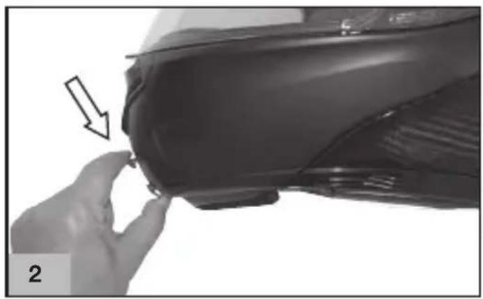
natural_image
Close-up of a hand adjusting a car seat component with an arrow indicating the adjustment (no text or symbols visible)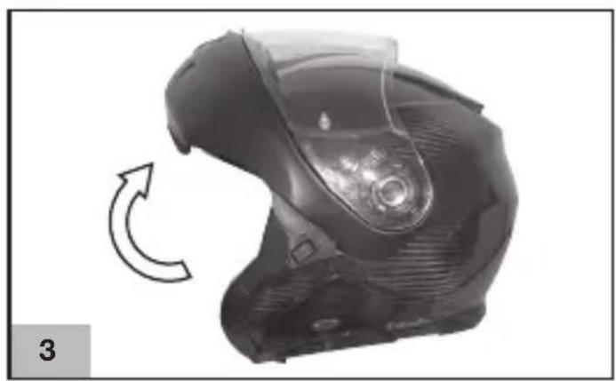
natural_image
Close-up of a black automotive helmet with a circular arrow indicating rotational motion (no text or symbols)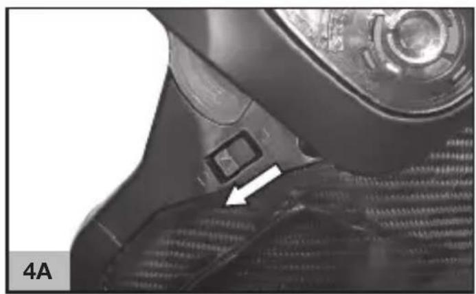
natural_image
Close-up of a car's side panel showing a button and textured surface, with no visible text or symbols.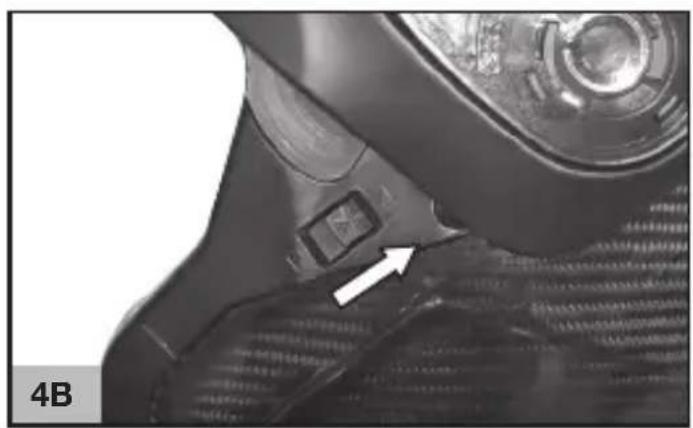
natural_image
Close-up of a car's side profile showing a white arrow pointing to a button on the lower side (no text or symbols visible)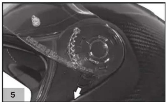
natural_image
Close-up of a car's wheel and head assembly (no visible text or symbols)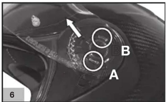
text_image
A B C 6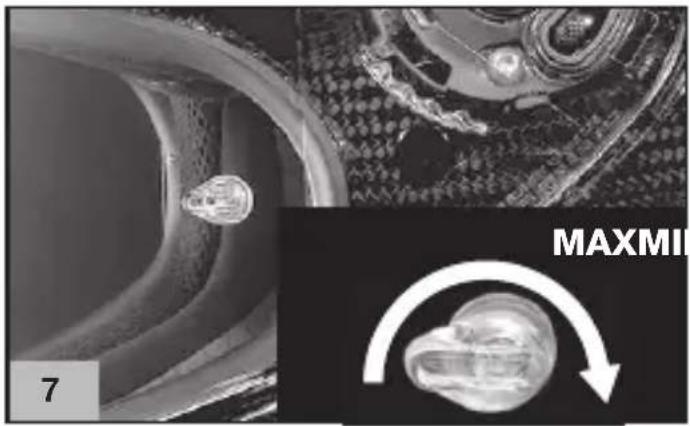
natural_image
Microscopic view of a mechanical component with a highlighted MAXMI annotation (no readable text or symbols)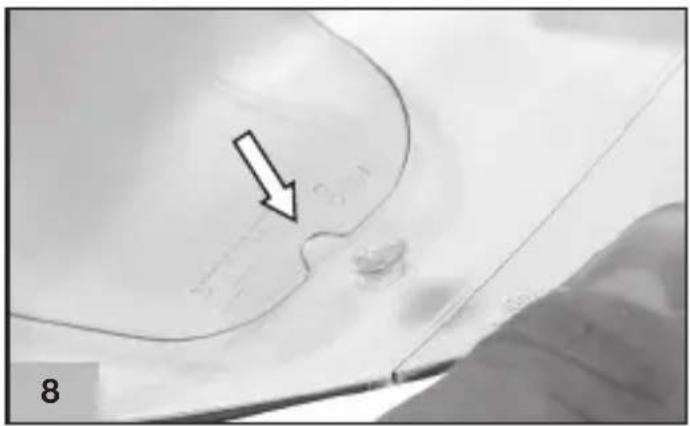
natural_image
Close-up of a curved surface with a black arrow pointing to a small feature, no visible text or symbols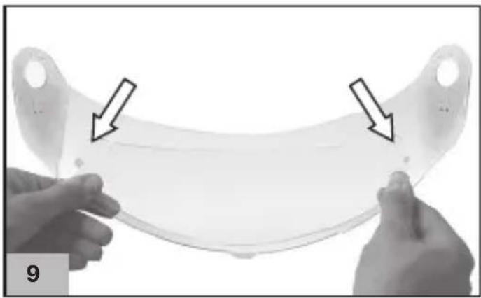
natural_image
Close-up of two hands holding a transparent plastic object with two arrows pointing to the surface (no text or symbols visible)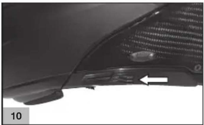
natural_image
Close-up of a car's side profile showing the nose and ear area, with a white arrow pointing to a specific area (no text or symbols visible)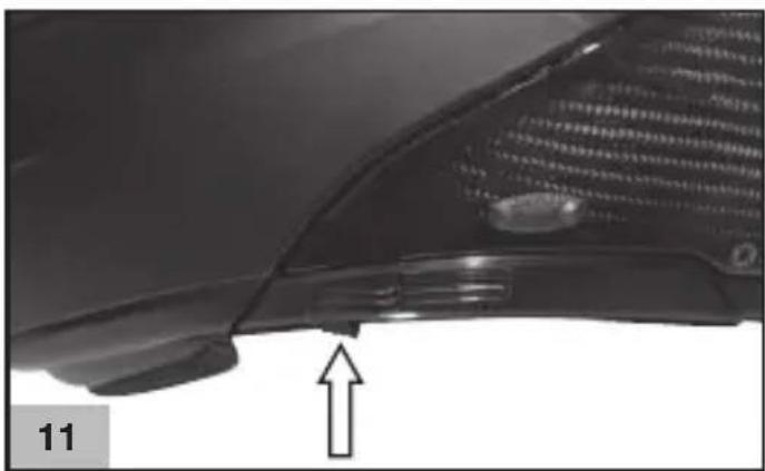
natural_image
Close-up of a car's side profile with a pointing arrow, no visible text or symbols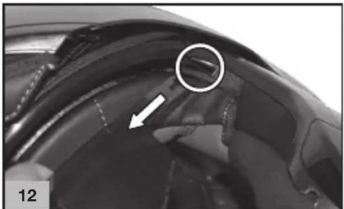
natural_image
Close-up of a mechanical component with a circled feature and an arrow indicator (no text or symbols)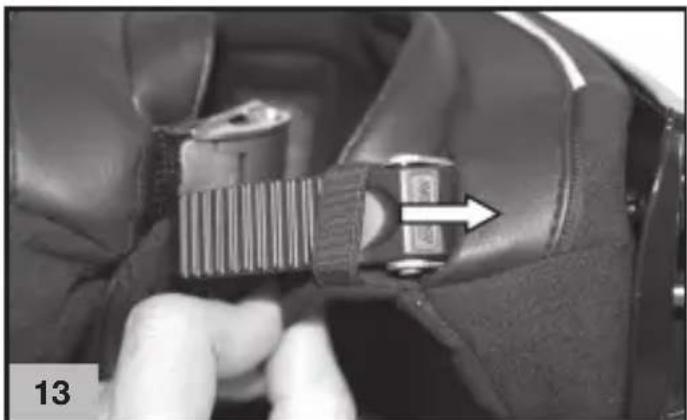
natural_image
Close-up of a hand adjusting a car seatbelt buckle, showing a finger insertion and arrow indicating direction (no text or symbols)FIG. - ABB. - EIK. - KUVA
natural_image
Close-up of a hand holding a black electronic device with three circular annotations highlighting specific components (no text or symbols visible)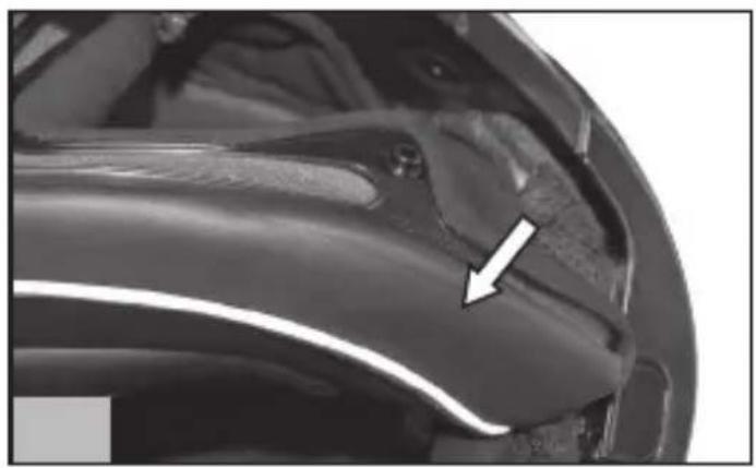
natural_image
Close-up of a car's side profile with a white arrow pointing to a specific area (no text or symbols visible)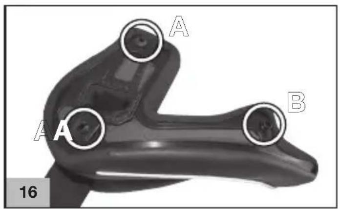
text_image
A A B 16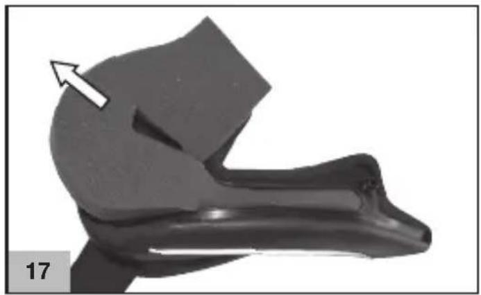
natural_image
Mechanical component with a white arrow indicating direction, no visible text or symbols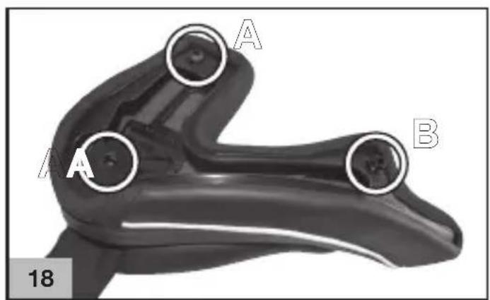
text_image
A A B 18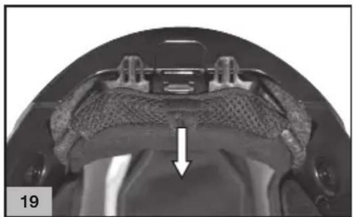
natural_image
Medical imaging scan showing a cross-sectional view of a dental implant or implant structure with an arrow indicating a specific area (no text or symbols present)
natural_image
Medical scan image showing anatomical structures with two white circles highlighting specific regions, no visible text or symbols.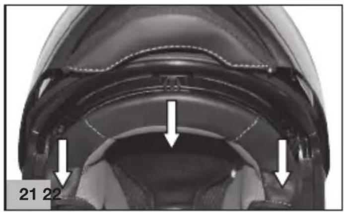
natural_image
Close-up of a mechanical component with two white arrows pointing to features, labeled '21 22' (no other text or symbols)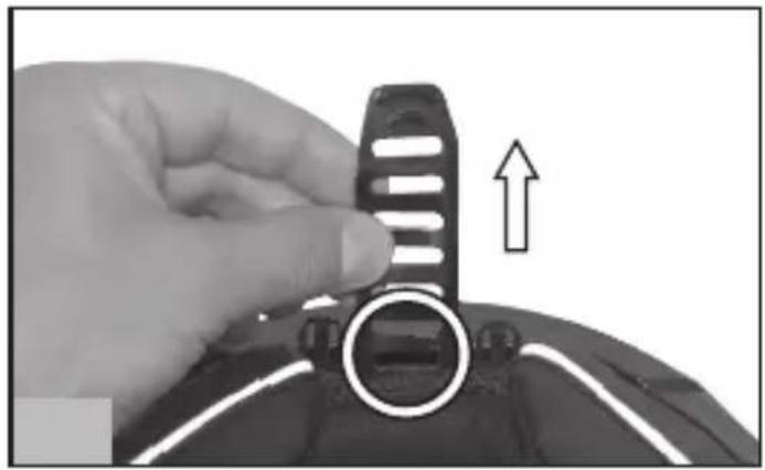
natural_image
Close-up of a hand holding a black mechanical component with an arrow indicating upward motion (no text or symbols visible)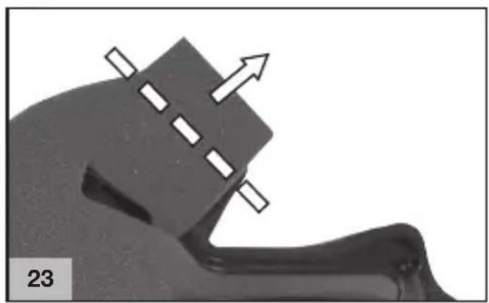
natural_image
Close-up of a mechanical component with arrows indicating direction, no visible text or symbols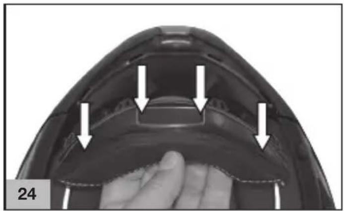
natural_image
Close-up of a hand holding a transparent plastic object with arrows pointing to features (no text or symbols visible)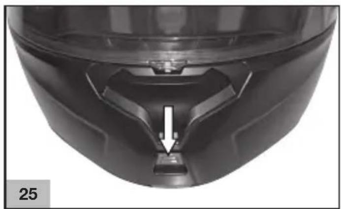
natural_image
Close-up of a black plastic helmet with a white arrow pointing to a small component, labeled '25' in the corner (no other text or symbols)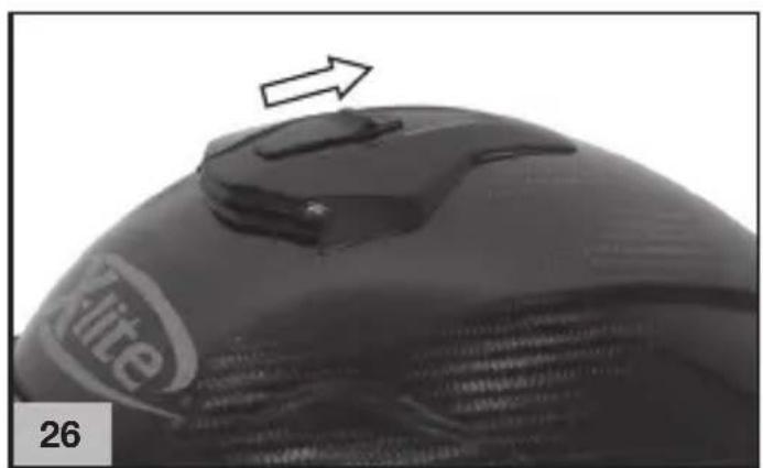
natural_image
Close-up of a black computer mouse with a white 'X-lite' logo and an arrow pointing to the top surface (no text or symbols on the object itself)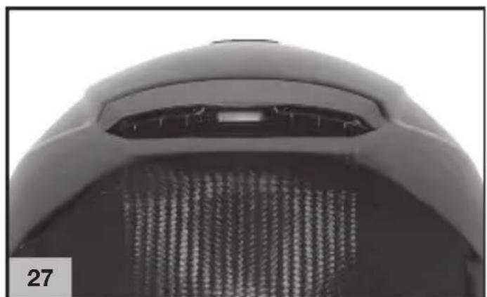
natural_image
Close-up of a mechanical component with mesh grille and central slot (no visible text or symbols)Note, Clipboard, Notizen, Notas, vóteç
Note, Clipboard, Notizen, Notas, vóteç
Note, Clipboard, Notizen, Notas, vóteç
Note, Clipboard, Notizen, Notas, vóteç
- Questo casco è prodotto in uno stabilimento che rispetta l'ambiente. Al termine del suo utilizzo, si raccomanda di effettuarne lo smaltimento, seguendo le specifiche normative di legge vigenti nel luogo o Paese di residenza.
- This helmet is manufactured in a plant respecting the environment. At the end of its use, it is recommended to dispose of it according to specific regulations in force over the place or Country of residence.
- Dieser Helm wurde mit größtmöglicher Rücksicht auf die Umwelt hergestellt. Nach Gebrauch entsorgen Sie ihn bitte entsprechend den landes- oder ortsüblichen Bestimmungen.
- Ce casque est fabriqué dans un établissement qui respecte l'environnement. À la fin de son utilisation, il est recommandé de procéder à son élimination, suivant les règles spécifiques en vigueur dans le lieu ou le pays de résidence.
- Este casco ha sido fabricado en una instalación industrial que respeta el medio ambiente. Una vez cumplido su servicio, para eliminarlo, se recomienda acudir a un centro de recogida selectiva y actuar según las normas vigentes en el lugar y país de residencia.
- Este capacete é produzido numa fábrica que respeita o ambiente. No final da sua utilização, recomenda-se que seja eliminado de acordo com regulamentação específica em vigor no local ou País de residência.
- Deze helm wordt op een milieu vriendelijke manier vervaardigd. Wanneer de helm niet meer gebruikt wordt dient u deze helm af te voeren volgens de geldende milieu eisen.
- Denne hjelm er lavet med respekt for miljøet. Når den engang skal bortskaffes, bør det være i overensstemmelse med miljøreglerne.
• Το κρανος αυτο εχει κατασκευαστει σε εργοστασιο που σεβεται το περιβαλλον. Μετα το περας της χρησης του συνισταται να το καταστρεψετε συμφωνα με τους κανονισμους που ισχυουν στο τοπο ή χωρα διαμονης σας.
NOIAN Technology
COMPOSITE FIBRE

text_image
ISTR000000167 - 07.2020 (Eletta)