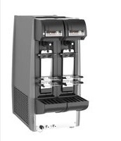
BEERMATIC DualTap DBF-AS65WE-EU-HC - Beer dispenser Hoshizaki - Free user manual and instructions
Find the device manual for free BEERMATIC DualTap DBF-AS65WE-EU-HC Hoshizaki in PDF.


| Product Type | Automatic double-tap beer dispenser |
| Brand | Hoshizaki |
| Model | BEERMATIC DualTap DBF-AS65WE-EU-HC |
| Power supply | Single-phase 220-240 V, 50 Hz |
| Dispensing capacity | 65 L (from 30°C to 8°C in 4 hours) |
| Ice formation time | 11 hours (water at initial 25°C) |
| Ice storage capacity | 12 L |
| Dimensions (W x D x H) | 367 x 674 x 764 mm |
| Net weight | 50 kg |
| Refrigerant | R600a (isobutane), 80 g |
| Ambient operating temperature | 5 to 32 °C |
| Cooling water temperature | ≤ 25 °C |
| Beer keg temperature | 10 to 30 °C |
| Max. CO2 pressure | 0.37 MPa |
| Number of taps | 2 (beer and foam) |
| Ecological materials | HFC-free refrigerant, HFC-free insulating foam |
| Beer circuit cleaning | Daily (rinsing), weekly (sponge) |
| Tap cleaning | Weekly (disassembly and cleaning) |
| Air filter cleaning | Every two weeks |
| Supplied accessories | Drip tray, grilles, platforms, nozzle caps, brushes, sponges, key, hook, fixing chain |
| Warranty | 1 year (parts and labor) |
Frequently Asked Questions - BEERMATIC DualTap DBF-AS65WE-EU-HC Hoshizaki
User questions about BEERMATIC DualTap DBF-AS65WE-EU-HC Hoshizaki
0 question about this device. Answer the ones you know or ask your own.
Ask a new question about this device
Download the instructions for your Beer dispenser in PDF format for free! Find your manual BEERMATIC DualTap DBF-AS65WE-EU-HC - Hoshizaki and take your electronic device back in hand. On this page are published all the documents necessary for the use of your device. BEERMATIC DualTap DBF-AS65WE-EU-HC by Hoshizaki.
USER MANUAL BEERMATIC DualTap DBF-AS65WE-EU-HC Hoshizaki
AUTOMATIC DRAFT BEER DISPENSER
TIREUSE A BIERE AUTOMATIQUE
AUTOMATISCHE BIERZAPFANLAGE
AUTOMATISCHE BIERTAPINSTALLATIE
DISPENSADOR AUTOMÁTICO DE CERVEZA DE BARRIL
SPILLATORE DI BIRRA AUTOMATICO
INSTRUCTION MANUAL
(original instructions)
NOTICE D'UTILISATION
[a] DISPENSER. 6
[b] DRAIN PAN 6
[c] PLATFORM ADJUSTMENT 7
-
ELECTRICAL CONNECTIONS 9
-
GAS AND BEER CIRCUIT CONNECTIONS 9
[a] CO2 GAS CYLINDER 9
[b] HOSE CONNECTIONS 10
[c] CHECKS AFTER CONNECTIONS 10
- CHECKS AFTER INSTALLATION 11
-
SOLD OUT SENSOR SETTING ("U07"). 11
-
USER SETTINGS 12
II. OPERATING INSTRUCTIONS 13
- CLEANING BEER CIRCUIT 13
- FILLING WATER TANK 13
[a]HOW TO MAKE COOLING WATER 13
[b] COOLING WATER SUPPLY 14
- CHECKS BEFORE OPERATION (DAILY). 14
[a] CHECKING CO2 GAS CYLINDER 14
[b] REPLACING CO2 GAS CYLINDER 14
[c] CHECKING BEER KEG 15
[d] REPLACING BEER KEG 15
- START UP 16
[a] SWITCHING MODE 16
[b] LEADING BEER TO TAP 16
- SETTING LIQUID AND FOAM AMOUNTS 16
[a] LARGER MUG SETTING 17
[b]SMALLER MUG SETTING 17
- DISPENSING 17
[a]AUTOMATIC DISPENSING 17
[b] STOPPING AUTOMATIC DISPENSING 18
[c]MANUAL DISPENSING 18
[d] SWITCHING TO AUTOMATIC DISPENSING MODE 19
- SOLD OUT SENSOR 19
8.END OF DISPENSING OPERATION 19
9. SHUT DOWN 19
[a] SHUT DOWN 19
[b] DRAINING WATER TANK 20
III. MAINTENANCE 20
- BASIC CLEANING 20
-
BEER CIRCUIT (DAILY) 21
-
DRAIN PAN AND GRILLE (DAILY) 22
- PLATFORM (DAILY) 22
- CLEANING BEER CIRCUIT WITH SPONGE (WEEKLY). 23
- DISASSEMBLY AND CLEANING OF BEER TAP (WEEKLY) 25
- KEG COUPLER (WEEKLY) 26
- EXTERIOR (WEEKLY) 26
9.AIR FILTER (BIWEEKLY) 26
IV. INSPECTION 26
- COOLING WATER AND ELECTRODE (BIANNUALLY) 26
- GAS HOSE AND BEER HOSE (MONTHLY) 27
- ATTACHMENT PLUG AND POWER CORD (ANNUALLY / BIANNUALLY) 27
V. OTHER INFORMATION 27
- PREPARING THE DISPENSER FOR LONG STORAGE 27
- BEFORE CALLING FOR SERVICE 28
- DISPOSAL 29
- WARRANTY 29
SPECIFICATIONS 30
FRANCAIS
INFORMATIONS IMPORTANTES RELATIVES A LA SECURITE 31
I. INSTRUCTIONS D'INSTALLATION 33
1.COMPOSANTS 33
2.ACCESSOIRES 34
3. DEBALLAGE 34
4. EMPLACEMENT 35
5. INSTALLATION 35
[a] TIREUSE 36
[b] PLATEAU EGOUTTOIR. 36
[c] REGLAGE DE LA PLATEFORME 37
- BRANCHEMENTS ELECTRIQUES 39
- BRANCHEMENTS DES CIRCUITS DE GAZ ET DE BIERE 39
[a] Bouteille de CO2 39
[b] RACCORDEMENTS DES TUYAUX 40
[c] CONTROLES A EFFECTUER APRES LES RACCORDEMENTS 41
V. INFORMATIONS DIVERSES 59
- PREPARATION DE LA TIREUSE EN VUE D'UN STOCKAGE PROLONGE 59
- AVANT D'APPELER UN REPARATEUR 60
- MISE AU REBUT 61
4.GARANTIE 61
CHARACTERISTIQUES 62
DEUTSCH
IMPORTANT SAFETY INFORMATION
Throughout this manual, notices appear to bring your attention to situations which could result in death, serious injury, or damage to the unit.
| ▲WARNING | Indicates a hazardous situation which, if not avoided, could result in death or serious injury. |
| ▲CAUTION | Indicates a hazardous situation which, if not avoided, could result in minor or moderate injury. |
| NOTICE | Indicates a hazardous situation which, if not avoided, could result in damage to the unit. |
| ▲HYGIENE | Indicates important precautions for hygiene and food safety. |
| IMPORTANT | Indicates important information about the use and care of the unit. |
This automatic draft beer dispenser uses HFC-free refrigerant (isobutane) and HFC-free foam insulation that are non-ozone-depleting and environmentally sustainable materials having very low global warming potential.
| ▲WARNING |
| This automatic draft beer dispenser contains flammable refrigerant in its cooling unit; installation, handling, servicing and disposal must therefore only be carried out by authorized technicians. |
| The refrigerant contained in this automatic draft beer dispenser is flammable and sealed in the refrigeration system. Although the refrigerant does not leak out under normal usage, take utmost care when handling this automatic draft beer dispenser so as not to cause any damages to the system. |
| In the case of accidental damage to the refrigeration system causing refrigerant leak:* Do not create a source of ignition in the area.* Do not operate electrical switches or plugs in the area.* Do not use naked flame.* Immediately ventilate the area by opening doors and/or windows.* Call service engineer. |
| IMPORTANT | |
| This booklet is an integral and essential part of the product and should be kept and preserved by the user. | |
| Please read carefully the guidelines and warnings contained herein as they are intended to provide the installer/user with essential information for the proper installation and the continued safe use and maintenance of the product. | |
| Please preserve this booklet for any further consultation that may be necessary. | |
| ▲WARNING | |
| This is a commercial automatic draft beer dispenser, and should be destined only to be used for the purpose for which it has been expressly designed. Any other use should be considered improper and therefore dangerous. The manufacturer will not be held liable or responsible for any damage caused by improper, incorrect and unreasonable use. | |
| The installation, and relocation if necessary, must be carried out by qualified personnel, in accordance with current regulations, according to the manufacturer's instructions. | |
| Keep ventilation openings, in the appliance enclosure or in the built-in structure, clear of obstruction. | |
| Do not damage the refrigerating circuit. | |
| The maintenance operations must be conducted by trained person. Access to the service area is restricted to persons having knowledge and practical experience of the appliance, in particular as far as safety and hygiene are concerned. | |
| The use of any electrical appliance involves the observance of some fundamental rules. In particular:* Instances of high humidity and moisture increase the risk of electrical short circuits and potential electrical shocks. If in doubt, disconnect the dispenser.* Do not damage the power cord or pull it in order to disconnect the dispenser from the electrical supply network.* If the supply cord and/or the plug should need to be replaced, it should only be done by a qualified service engineer.* Do not touch the electrical parts or operate the switches with damp hands.* This appliance is not intended for use by persons (including children) with reduced physical, sensory or mental capabilities, or lack of experience and knowledge, it can however be used by children aged from 8 years and above and persons with reduced physical, sensory or mental capabilities, or lack of experience and knowledge providing they have been given supervision or instruction concerning use of the appliance by a person responsible for their safety.* Children shall not play with the appliance.* Cleaning and user maintenance shall not be made by children without supervision.* Do not attempt to modify the dispenser. Only qualified personnel may disassemble or repair the appliance. | |
| When positioning the appliance, ensure the supply cord is not trapped or damaged. | |
| Do not locate multiple portable socket-outlets or portable power supplies at the rear of the appliance. | The meaning of this ISO 7010 W021 symbol is:Warning: Risk of fire |
I. INSTALLATION INSTRUCTIONS
1. CONSTRUCTION
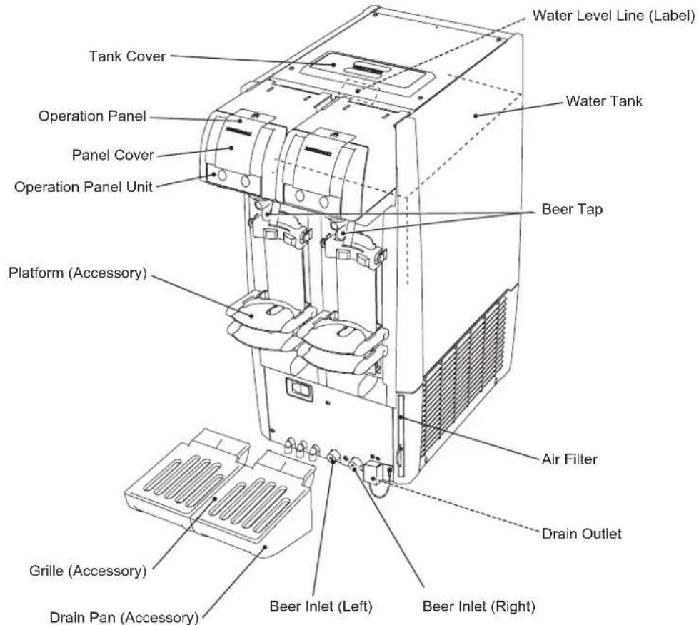
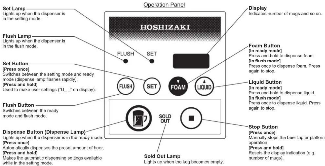
NOTICE
Open the panel cover to access the buttons and lamps other than the dispense button (dispense lamp), sold out lamp and stop button.
To prevent damage to the panel cover, do not open it by force.
Prepare and install the following equipment. Consult with the liquor shop, beer company or distributor to prepare the regulator, keg coupler and CO2 gas cylinder designed for the beer to dispense.
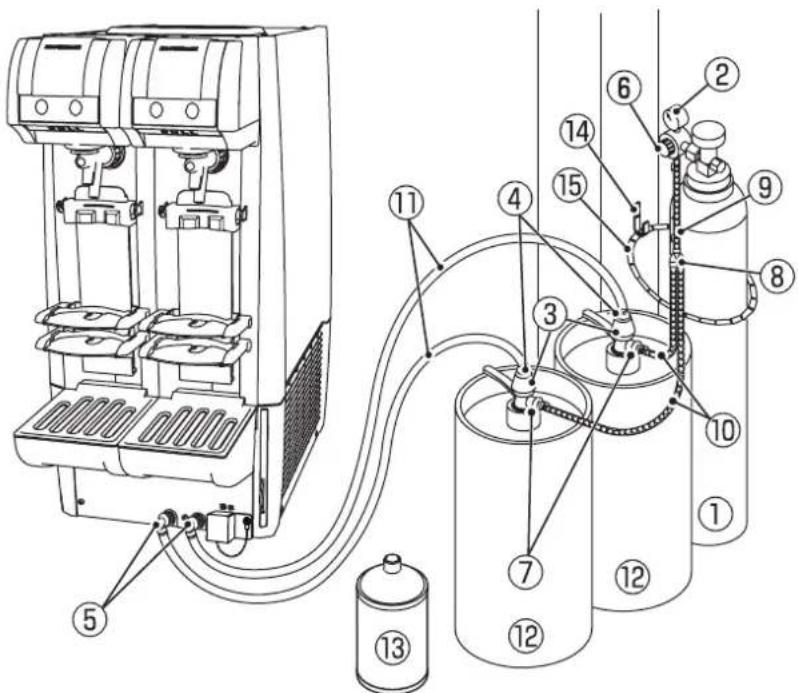
[1] CO2 Gas Cylinder
[2] Regulator
[3] Keg Coupler
[4] Quick Beer Hose Joint (Coupler Side)
[5] Quick Beer Hose Joint (Dispenser Side)
[6] Quick Gas Hose Joint (Regulator Side)
[7] Quick Gas Hose Joint (Coupler Side)
[8] Y-Tee
[9] Gas Hose (Short)
[10] Gas Hose (Long)
[11] Beer Hose
[12] Beer Keg
[13] Cleaning Tank
[14] Hook (Accessory)
[15] Cylinder Chain (Accessory)
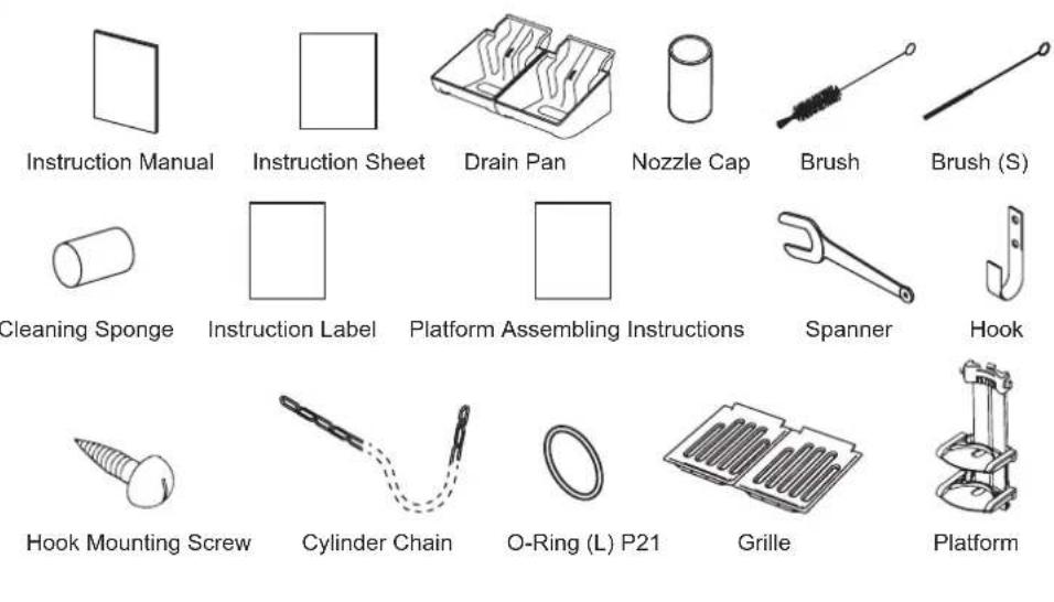
2. ACCESSORIES
| Instruction Manual 1 | |
| Instruction Sheet 1 | |
| Drain Pan 2 | |
| Nozzle Cap 8 | |
| Brush 1 | |
| Brush (S) 1 | |
| Cleaning Sponge 6 | |
| Instruction Label 1 | |
| Platform Assembling Instructions | 1 |
| Spanner 1 | |
| Hook 1 | |
| Hook Mounting Screw 2 | |
| Cylinder Chain 1 | |
| O-Ring (L) P21 1 | |
| Grille 2 | |
| Platform 2 |
3.UNPACKING
| ▲WARNING |
| Children should not be allowed in reach of the packaging elements (plastic bags and expanded polystyrene) as they are potential sources of danger. |
| ▲CAUTION |
| Do not lift or manoeuvre the carton by using the shipping bands. |
| When moving the unit by hand, hold the unit bottom. |
| Do not hold the beer tap to lift up the unit. The beer tap may be damaged or the unit may fall causing injury. |
| Always wear protective gloves when carrying the unit. |
| When handling the carton or the unpacked unit, work in pair to prevent injury. |
| NOTICE |
| Remove shipping carton, tape(s) and packing. If packing material is left in the dispenser, it will not work properly. |
| To prevent damage, do not tilt the dispenser more than 45°. |
1) After removing the packaging, make sure that the dispenser is in good condition. If in doubt, please do not use the dispenser but apply to professionally qualified personnel.
2) Remove the protective plastic film from the exterior. If the dispenser is exposed to the sun or to heat, remove the film after the dispenser cools.
3) Remove the package of accessories. Check the contents according to "2. ACCESSORIES".
4. LOCATION
| ▲WARNING |
| This dispenser is not intended for outdoor use. |
| The dispenser should not be located next to ovens, grills or other high heat producing equipment. |
| This appliance is not suitable for installation in an area where a water jet could be used. |
| CAUTION |
| The location should provide a firm and level foundation for the dispenser. |
| NOTICE |
| Do not place anything to obstruct the ventilation louvers. |
| IMPORTANT |
| Normal operating ambient temperature should be within 5°C to 32°C, cooling water temperature not more than 25°C, and beer keg temperature within 10°C to 30°C. Operation of the dispenser, for extended periods, outside of these normal temperature ranges may affect production capacity. |
| Allow 10 mm extra space at the installation site to meet any installation requirements (additional spacing is also required for proper air flow and pipe connections). |
| Keep the dispenser away from direct sunlight. |
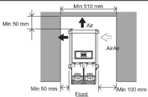
Allow the clearance specified below for proper air circulation and ease of maintenance and/or service should they be required.
In some high humidity environments, condensation may form inside the machine and drip onto the floor. Do not install where the floor can be affected by water.
Avoid prolonged exposure of the appliance to direct sunlight.
5. INSTALLATION
| CAUTION |
| Incorrect installation can cause harm to people, animals or other items, for which the manufacturer cannot be held responsible. |
[a] DISPENSER
The front rubber feet can be moved backward from their original position. If the feet cannot fit within the installation space on the counter or table, use a screwdriver to remove the front feet from the bottom and refit at the following positions.
| Factory Setting | Distance: A 274 mm |
| Distance: B 388 mm | |
| After Adjustment | Distance: a 244 mm |
| Distance: b 328 mm |
![Hoshizaki BEERMATIC DualTap DBF-AS65WE-EU-HC - [a] DISPENSER - 1](/content/2026/04/704246/images/a6750c99245e1c902a8c6c26f32cb7528db36057efe831ef1af175523bc60296.jpg)
![Hoshizaki BEERMATIC DualTap DBF-AS65WE-EU-HC - [a] DISPENSER - 2](/content/2026/04/704246/images/b4b5df916a7ec800889f65d78a2f29d1cef403b0bfb44fd7c0f49e901f2f0e67.jpg)
[b] DRAIN PAN
To attach the drain pan (accessory) and grille (accessory):
(1) lift up the front of the drain pan,
(2) push the drain pan securely into the drain pan support, and
(3) push down the front of the drain pan.
![Hoshizaki BEERMATIC DualTap DBF-AS65WE-EU-HC - [b] DRAIN PAN - 1](/content/2026/04/704246/images/1ca1c64493ecbeafacbef5529e769dfb2ea4373a5492175656c6ef0bbb831dea.jpg)
![Hoshizaki BEERMATIC DualTap DBF-AS65WE-EU-HC - [b] DRAIN PAN - 2](/content/2026/04/704246/images/c778418b013c0f0cac1b9e8727be223cf3f7db1a18f8d09952e2ecc3d0027018.jpg)
![Hoshizaki BEERMATIC DualTap DBF-AS65WE-EU-HC - [b] DRAIN PAN - 3](/content/2026/04/704246/images/2ba78caffc883673984750e5aec476b67c38975c4f6afcea0111da74313f9cf4.jpg)
After installation of accessories
[c] PLATFORM ADJUSTMENT
The upper and lower platform positions are adjustable to accommodate two different mug heights. The guide can also be moved back and forth according to the mug shape.
1) The platform assembly has the components as shown on the right.
![Hoshizaki BEERMATIC DualTap DBF-AS65WE-EU-HC - [c] PLATFORM ADJUSTMENT - 1](/content/2026/04/704246/images/3c4f25652acfc698c499db2cf821a8ecdd3130602f10aebb4c3554557529c343.jpg)
2) Move the platform in the desired position and secure it with the screws. The upper platform position is adjustable between the 1st and 7th levels of the mug plate, and the lower platform position between the 4th and 12th levels. The top of the mug must fit the mark on the back plate when positioned on the platform. (See the table on the next page for the mug heights and platform positions.)
![Hoshizaki BEERMATIC DualTap DBF-AS65WE-EU-HC - [c] PLATFORM ADJUSTMENT - 2](/content/2026/04/704246/images/ff2708d7a71785b2b99df74bc705ad30c6d731690d496ea1391e2365d0bde48f.jpg)
3) After adjusting the platform positions, fit the guide to position the bottom of the mug. The guide with cover is for the upper platform.
![Hoshizaki BEERMATIC DualTap DBF-AS65WE-EU-HC - [c] PLATFORM ADJUSTMENT - 3](/content/2026/04/704246/images/260ac9866106c1d7f3b78f6831ee75cae05a169759d1298add1c98528209cde8.jpg)
![Hoshizaki BEERMATIC DualTap DBF-AS65WE-EU-HC - [c] PLATFORM ADJUSTMENT - 4](/content/2026/04/704246/images/9eb7c46b1e71878232fa2e99322c353a69981b643c2f21e28b403c6a9753762f.jpg)
4) Refit the platforms to the unit.
NOTICE
When adjusting the upper platform position, also adjust the bracket position according to the table on the next page.
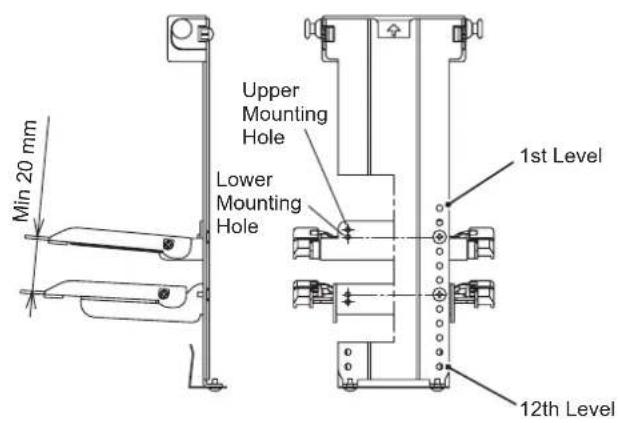
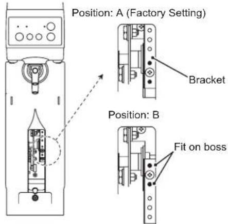
Bracket Position Platform Position
| Mug Plate Level | Upper Platform Lower Platform | ||||
| Mounting Hole Mug Height (mm) Bracket Position Mounting Hole Mug Height (mm) | |||||
| 1 | Lower 135 | A | Not available | ||
| Upper 140 | |||||
| 2 | Lower 145 | ||||
| Upper 150 | |||||
| 3 | Lower 155 | ||||
| Upper 160 | |||||
| 4 | Lower 165 Lower 155 | ||||
| Upper 170 | B | Upper 160 | |||
| 5 | Lower 175 Lower 165 | ||||
| Upper 180 Upper 170 | |||||
| 6 | Lower 185 Lower 175 | ||||
| Upper 190 Upper 180 | |||||
| 7 | Lower 195 Lower 185 | ||||
| Upper 200 Upper 190 | |||||
| 8 | Not available | Lower 195 | |||
| Upper 200 | |||||
| 9 | Lower 205 | ||||
| Upper 210 | |||||
| 10 | Lower 215 | ||||
| Upper 220 | |||||
| 11 | Lower 225 | ||||
| Upper 230 | |||||
| 12 | Lower 235 | ||||
| Upper 240 | |||||
| Note:1) Mug diameter: 50 mm inside diameter to 105 mm outside diameter and bottom diameter2) The larger mug must be at least 20 mm higher than the smaller mug. | |||||
6. ELECTRICAL CONNECTIONS
| ▲WARNING |
| THIS APPLIANCE MUST BE EARTHED This dispenser requires an earth that meets the national and local electrical code requirements. |
| To prevent possible severe electrical shock to individuals or extensive damage to the unit, install a proper earth wire to the dispenser. |
| Remove the plug from the mains socket before any maintenance, repairs or cleaning is undertaken. |
| CAUTION |
| The maximum allowable voltage variation should not exceed ±10 percent of the rated voltage. Operation of the unit outside of this range may cause smoking, ignition, damage to the unit or reduction of the performance. |
- This appliance requires a separate power supply. The electrical supply must be protected by a suitable circuit breaker.
- Usually an electrical permit and services of a licensed electrician are required.
- If the supply cord is damaged, it must be replaced by a replacement cord available from your dealer/supplier.
7. GAS AND BEER CIRCUIT CONNECTIONS
[a] CO2 GAS CYLINDER
| ▲WARNING |
| Use a CO2 gas cylinder designed for use with beer. Use of any other cylinders may cause explosion or air pollution. |
| While carrying the CO2 gas cylinder, keep the cap closed and avoid any impact on the cylinder to prevent the risk of explosion or gas leaks. |
| Keep the CO2 gas cylinder away from direct sunlight or temperatures above 40°C to avoid excessive temperature rise and explosion. |
| The regulator must be provided with an undamaged gasket to prevent the risk of gas leaks. If not, contact the liquor shop, beer company or distributor to install a new gasket. |
| Stand the CO2 gas cylinder upright, and fix it securely with the accessory chain to prevent overturn resulting in injury or explosion. |
| Keep your face away from the CO2 gas cylinder while blowing dirt and dust off the regulator joint. Dust getting in your eyes can cause visual impairment. |
| Handle the regulator with care to avoid any impact, or it may not work properly and the beer keg or hose can explode. |
| Before opening the main valve of the CO2 gas cylinder or removing the keg coupler from the beer keg, set the regulator to "0". Otherwise, sudden application of gas pressure on the beer keg may cause explosion or blow-off of the keg coupler. |
1) Open the main valve of the new CO2 gas cylinder for a second to blow dirt and dust off the joint (together with CO2 gas).
2) Check the regulator gasket. If it is damaged or not provided install a new gasket. (Contact the liquor shop, beer company or distributor.)
3) Install the regulator securely on the CO2 gas cylinder.
NOTICE
- Tighten the nut by hand first, then with the spanner (accessory) so that the level gauge will be upright.
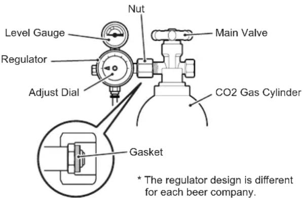
4) Open the main valve by turning it counterclockwise, and check the regulator nut for gas leak (sound). If gas is leaking, the nut must be loose or the gasket must be damaged or not provided.
Note: To check for gas leaks, apply a sponge with soap to the joint. Bubbles form if gas is leaking.
[b] HOSE CONNECTIONS
| ▲WARNING |
| To prevent the risk of gas leaks and hose explosion, do not use any hoses other than specified by the beer company. |
| Cut the hose end to have a vertical cutting plane and insert it securely into the quick hose joint to ensure a leak-free joint. |
| NOTICE |
| Do not reconnect the hoses without cutting them about 20 mm. |
| Cut the hoses with a specialized tool such as hose cutter. Do not use scissors, or the hoses may be crushed to cause leaks. |
CO2 Gas Hose
1) Cut the CO2 gas hose to have a vertical cutting plane and a hose length not more than 1.4m .
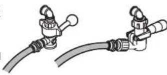
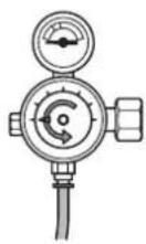
2) Insert the CO2 gas hose securely into the quick gas hose joint on the keg coupler and regulator. Pull the hose hard to check for tightness.
Rotary Type Vertical Type
Keg Coupler Regulator
Quick Gas Hose Joint
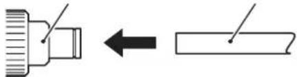
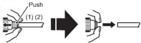
1) To connect the CO2 gas hose, push it all the way in.
2) To disconnect the CO2 gas hose, push and hold part (1) with fingers and pull out the hose (2).
Quick Gas Hose Joint Gas Hose
Beer Hose
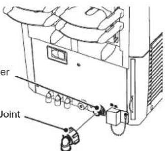
1) Attach the quick beer hose joint specified by the beer company to the beer hose adapter. Beer Hot
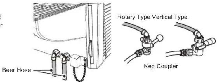
2) Cut the beer hose to have a vertical cutting plane and a hose length not more than 2.1m .
3) Insert the beer hose securely into the keg coupler and quick beer hose joint. Pull the hose hard to check for tightness.
Note: It depends on the beer company how to connect and disconnect the beer hose to and from the quick beer hose joint.
[c] CHECKS AFTER CONNECTIONS
1) Wash the cleaning tank thoroughly and fill it with tap water.
Note: If the cleaning tank is not clean, the beer circuit will be contaminated.
2) Turn the keg coupler clockwise to attach it to the cleaning tank.
Note: Wash the joint between the keg coupler and cleaning tank if it is not clean.
3) Lift up and remove the platform.
4) Place a bucket on the drain pan to receive cleaning water.
![Hoshizaki BEERMATIC DualTap DBF-AS65WE-EU-HC - [c] CHECKS AFTER CONNECTIONS - 1](/content/2026/04/704246/images/ffcc0c16493d229b19f5c826b8166a647c39bc1129646befc7cf849568862959.jpg)
5) Check that the beer tap lever is in the closed (normal) position. Open the main valve of the CO2 gas cylinder by turning it counterclockwise a few times.
6) Turn the regulator adjust dial to set the pressure to "0.15" (MPa).
7) Open the beer circuit.
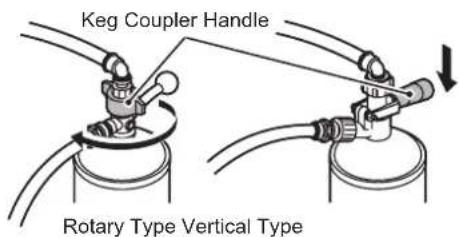
Rotary type: Turn the keg coupler handle clockwise until it stops.
Vertical type: Push down the keg coupler handle until it locks in place.
![Hoshizaki BEERMATIC DualTap DBF-AS65WE-EU-HC - [c] CHECKS AFTER CONNECTIONS - 2](/content/2026/04/704246/images/f357637c34a7f2362d219b44f848d892d7039c7091a65a712ac095a85cd7c033.jpg)
Closed Position
![Hoshizaki BEERMATIC DualTap DBF-AS65WE-EU-HC - [c] CHECKS AFTER CONNECTIONS - 3](/content/2026/04/704246/images/afc444e2d24fa28baa9f98cd351bad7f5144113737149bed3807aa39d7de580a.jpg)
CO2 Gas Cylinder
Note: If the cleaning tank is provided with a siphon tube, lay the cleaning tank with the ferrule at the top. If not, lay the cleaning tank with the ferrule at the bottom.
![Hoshizaki BEERMATIC DualTap DBF-AS65WE-EU-HC - [c] CHECKS AFTER CONNECTIONS - 4](/content/2026/04/704246/images/d17f33065e57d9e15761ae584a9e181b9cbf454cb08bea43e68b2e41d7f512ab.jpg)
Rotary Type Vertical Type
![Hoshizaki BEERMATIC DualTap DBF-AS65WE-EU-HC - [c] CHECKS AFTER CONNECTIONS - 5](/content/2026/04/704246/images/2e6e6b5c6c868e156bee8b5d8583d010c210629d526bbd32ddbb5066922c9760.jpg)
Provided Not provided
8) Pull the beer tap lever toward you to pour water out of the liquid nozzle.
9) Check the CO2 gas circuit for gas leaks. If it is leaking, correct the hose connections.
10) Check the beer circuit for water leaks. If it is leaking, correct the hose connections.
11) Keep the beer tap lever in the open position and turn the regulator adjust dial to set the pressure to "0" (MPa).
12) Close the main valve of the CO2 gas cylinder by turning it clockwise.
13) When CO2 gas stops coming out of the nozzle, push the beer tap lever back to the closed position.
![Hoshizaki BEERMATIC DualTap DBF-AS65WE-EU-HC - [c] CHECKS AFTER CONNECTIONS - 6](/content/2026/04/704246/images/9b7b7c1a10e9de13f1c257fd2f2d154229184c69785a4ca261415c03412a25bb.jpg)
![Hoshizaki BEERMATIC DualTap DBF-AS65WE-EU-HC - [c] CHECKS AFTER CONNECTIONS - 7](/content/2026/04/704246/images/467df8465a997d82b0894c251e042e14ea161e6f204ebce4fffe6538c0c11cf6.jpg)
CO2 Gas Cylinder
![Hoshizaki BEERMATIC DualTap DBF-AS65WE-EU-HC - [c] CHECKS AFTER CONNECTIONS - 8](/content/2026/04/704246/images/26077d827a9837e6fba2442e518ca7f8d8d70c888947fbb1ebc464cc3840c076.jpg)
Closed Position
8. CHECKS AFTER INSTALLATION
1) Fill the water tank with the specified water. See "II. 2. FILLING WATER TANK".
2) Flush the beer circuit and check for water leaks. See "III. 2. BEER CIRCUIT (DAILY)".
3) Check for proper power supply voltage.
4) Plug in the unit.
- Check that the refrigeration unit and agitator motor start.
(In low temperature conditions, the condenser fan motor may not start until the condenser temperature goes up.)
- After 8 to 13 hours (depending on ambient/water temperature), open the top cover and check that ice is stored in the water tank.
5) Instruct the user on how to operate the unit.
6) Hand this instruction manual to the user.
9. SOLD OUT SENSOR SETTING ("U07")
Choose among the four modes according to the type of beverage to dispense (e.g. beer, cocktail).
1) Lower the operation panel unit on the desired side.
2) Press and hold the set button on the operation panel to show "U01" on the display.
3) Use the foam button or liquid button to show "U07" on the display.
4) Press the set button to show the current number on the display. Use the foam button or liquid button to choose the desired number (see table below). Press the set button to set the flashing number.
| No. Setting |
| 0 Setting A (mainly beer) |
| 1 Setting B (mainly cocktail) |
| 2 Setting C (mainly cocktail) |
| 3 Setting D (optional) |
Note: The sold out sensor is factory set to "0: Setting A (mainly beer)". The setting depends on the brand of beverage to dispense. Check with your dealer/supplier.
5) Press the set button again to show "U07" on the display. Press and hold the set button for more than 3 seconds to complete the setting.
Note: If no operation is performed for more than 1 minute, the dispensing mode is resumed. In that case, go back to step 2) above.
10. USER SETTINGS
To make or change settings:
Press and hold the set button for 3 seconds to enter the setting mode (see "9. SOLD OUT SENSOR SETTING ("U07")".
To complete settings:
With "U_ _" on the display, press and hold the set button for 3 seconds to enter the dispensing mode.
The dispensing mode is also resumed if no operation is performed for more than 1 minute.
| Item Description | Default Setting Range | |||
| U01 | Digital display(in dispensing mode) | 0: No indication1: Number of mugs (*)* Number switches between the larger and smaller mugs when the mug setting is changed.* To reset, press and hold the stop button for 3 seconds. | 0 0 - 1 | |
| U02 | Log of number of mugs | Log of number of mugs for each reset in descending order* Log is indicated in turn for each keg replacement by "U04".* Log is indicated for both larger and smaller mugs when the mug setting is changed.* To reset all the current and past logs, press and hold the stop button for 3 seconds. This reset is not counted for "U04". | 0 Up to 5 logs | |
| U03 | Number of flush cycles | Number of flush cycles performed*A flush cycle consists of liquid button operation (total 10 seconds) + foam button operation (total 3 seconds) in the flush mode except when no automatic dispensing action is made during the cycle.* To reset, press and hold the stop button for 3 seconds. | 0 0 - 9999 | |
| U04 | Number of keg replacements(reset frequency) | Reset frequency for number of mugs*Keg replacement is counted every time the number of kegs is reset by the stop button operation.* To reset, press and hold the stop button for 3 seconds. | 0 0 - 9999 | |
| U05 | Dispense lampbrightness | Adjustment of dispense lamp brightness 6 1 - 8 | ||
| U06 | Dispense lamp flashingduration | Adjustment of dispense lamp flashing duration after completion dispensing* The dispense lamp flashes to prevent another mug is placed while foam is still dripping.* Automatic dispensing action is not available while the lamp is flashing. | 1 | 0 - 10 |
| U07 | Sold out sensor setting | 0: Setting A (mainly beer) / threshold: 2.2V1: Setting B (mainly cocktail) / threshold: 2.5V2: Setting C (mainly cocktail) / threshold: 2.8V3: Setting D (optional) / threshold: optional* The setting depends on the brand of beverage to dispense. Check with your dealer/supplier. | 0 0 - 3 | |
| U08 Self mode setting | 0: No 1: Yes (no button operation is available except dispense/stop button) * The self mode is reset when the manual dispensing mode is selected (by lifting up the operation panel unit). To resume the self mode, switch to the automatic dispensing mode (by pulling down the operation panel unit) and press the dispense button. | 0 0 -1 |
| U09 Mug tilting operation | 0: Yes (mug is tilted while beer is being dispensed) 1: No (mug is kept upright while beer is being dispensed) | 0 0 -1 |
| U10 Reset number of mugs | 0: Manual 1: Manual or when sold out sensor detects * To reset manually, press and hold the stop button for 3 seconds. | 0 0 -1 |
| U90 Reset settings | Initialize only the user settings * To initialize, with “1” shown on the display, press and hold the stop button for 3 seconds. * If the settings are updated, “U90” appears on the display. If not updated, “0” appears again. | 0 0 -1 |
II. OPERATING INSTRUCTIONS
1. CLEANING BEER CIRCUIT
Although the beer circuit is cleaned before shipping, clean it again before use. See "III. 2. BEER CIRCUIT (DAILY)".
Check that the parts are installed in their correct positions. See "I. 1. CONSTRUCTION".
2. FILLING WATER TANK
| NOTICE |
| Use only the specified water to fill the water tank. Use of any other water or mixture of salt, vinegar or juice may cause insufficient ice storage, corrosion or perforation. |
[a] HOW TO MAKE COOLING WATER
| IMPORTANT |
| Carefully read this before filling the water tank. |
Electric conductivity (E.C.) of cooling water for water tank
Do not use tap water.
Fill the water tank with water having 100 - 300~ S / cm of E.C.
Measure the electric conductivity with conductivity meter.
- E.C.: Physical property to show the ability of conducting electricity.
Unit: S (microsiemens)/cm
Below 100~ S / cm
Compressor may not work resulting in poor cooling performance.
Above 300~ S / cm
Excessive ice may build up on evaporator and freeze beer inside beer coil preventing beer from being dispensed properly.
How to make cooling water with 100 - 300~ S / cm of E.C.
The capacity of the water tank of this unit is approx. 30L
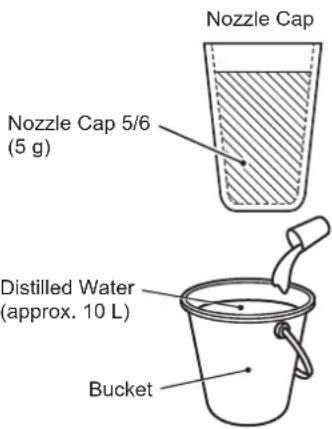
Make the cooling water by dissolving 5g of pure baking soda in approx. 10L of distilled water, and then add approx. 20L of distilled water to fill the water tank.
Step 1
Measure 5 g of pure baking soda with nozzle cap (accessory).
Step 2
Fill a bucket with approx. 10L of distilled water and stir well after adding the 5g of baking soda measured in step 1.
Rinse the nozzle cap after use.
[b] COOLING WATER SUPPLY
WARNING
Before filling the water tank, turn off the power switch (earth leakage breaker) and unplug the unit.
NOTICE
Do not splash water on the electrical parts.
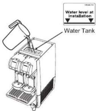
Do not fill the water tank above the water level line, or the drain pan will overflow and spill water.
1) Remove the top cover.
2) Pour the bucket (approx. 10 L) of cooling water prepared.
3) Fill the water tank up with approx. 20L of distilled water to the water level line marked inside the water tank.
4) Use a conductivity meter if measuring the electric conductivity.
5) Close the top cover.
3. CHECKS BEFORE OPERATION (DAILY)
[a] CHECKING CO2 GAS CYLINDER
Open the main valve of the CO2 gas cylinder, and check the gas pressure by the level gauge of the regulator:
- If the level gauge reading is not more than 3MPa or falls into the yellow zone, the cylinder contains little CO2 gas.
- If the level gauge reading is not more than 1 MPa or falls into the red zone, replace with a new cylinder.
![Hoshizaki BEERMATIC DualTap DBF-AS65WE-EU-HC - [a] CHECKING CO2 GAS CYLINDER - 1](/content/2026/04/704246/images/fe5f6299eb7320d31e4888d4db9839c610a555534ad61860fe6c7d5e35d9db50.jpg)
[b] REPLACING CO2 GAS CYLINDER
1) Close the main valve of the CO2 gas cylinder by turning it clockwise.
2) Turn the regulator adjust dial to set the pressure to "0" (MPa).
3) Use the spanner (accessory) to loosen the nut and remove the regulator from the CO2 gas cylinder.
Note: Be sure to cap the CO2 gas cylinder.
4) Open the main valve of the new CO2 gas cylinder for a second to blow dirt and dust off the joint (together with CO2 gas).
5) Check the regulator gasket. If it is damaged or not provided, install a new gasket. (Contact the liquor shop, beer company or distributor.)
6) Install the regulator securely on the CO2 gas cylinder.
![Hoshizaki BEERMATIC DualTap DBF-AS65WE-EU-HC - [b] REPLACING CO2 GAS CYLINDER - 1](/content/2026/04/704246/images/2e22863472705354703cdbd70db30bef3d9bd5ae242801721a5f48acdd91a7ae.jpg)
NOTICE
Tighten the nut by hand first, then with the spanner (accessory) so that the level gauge will be upright.
7) Open the main valve by turning it counterclockwise, and check the regulator nut for gas leak (sound). If gas is leaking, the nut must be loose or the gasket must be damaged or not provided.
Note: To check for gas leaks, apply a sponge with soap to the joint. Bubbles form if gas is leaking.
8) Turn the regulator adjust dial to set to an appropriate pressure as shown below.
WARNING
The CO2 gas pressure on the beer keg must not exceed 0.37 MPa. Otherwise, the beer keg or hose can explode resulting in injury.
The CO2 gas pressure on the beer keg prevents separation of CO2 gas from beer. The higher the beer keg temperature is, the easier the CO2 gas separates and a higher gas pressure is required.
| Beer Keg Temperature Gas Pressure | |
| 10°C 0.20 MPa | (Scale 2) |
| 20°C 0.22 MPa | (Scale 2.2) |
| 30°C 0.32 MPa | (Scale 3.2) |
Note: The values are for reference only. Set to the appropriate pressure specified by the beer company.
[c] CHECKING BEER KEG
If the sold out lamp comes on and no more beer is dispensed, replace the beer keg. Do not store an open beer keg in a refrigerator. But keep it under 30^ .
[d] REPLACING BEER KEG
WARNING
Do not loosen the ferrule on the beer keg, or inside pressure may blow off the ferrule resulting in injury.
Handle the beer keg with care to avoid vibration. Rolling or shaking the beer keg can cause excessive foaming.
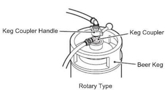
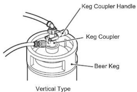
1) Close the beer circuit.
Rotary type: Turn the keg coupler handle counterclockwise until it stops. Vertical type: Unlock and lift the keg coupler handle all the way up.
2) Turn the regulator adjust dial to set the pressure to "0" (MPa).
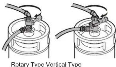
3) Turn the keg coupler counterclockwise to remove it from the beer keg.
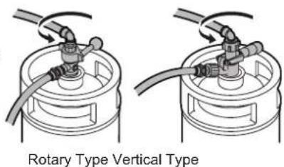
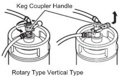
4) Turn the keg coupler clockwise to attach it to the new beer keg.
Note: Wash the joint between the keg coupler and beer keg if it is not clean.
5) Turn the regulator adjust dial to set to an appropriate pressure according to the beer keg temperature. See "[b] REPLACING CO2 GAS CYLINDER".
6) Open the beer circuit.
Rotary type: Turn the keg coupler handle clockwise until it stops.
Vertical type: Push down the keg coupler handle until it locks in place.
7) Before dispensing beer, lead beer to the beer tap according to "4. [b] LEADING BEER TO TAP".
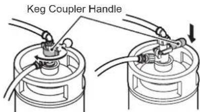
Rotary Type Vertical Type
4. START UP
| ▲WARNING |
| In case of a gas leak, turn off the main gas supply and ventilate the room. To prevent sparks and resulting fire and explosion, do not unplug the unit. |
| Do not use combustible spray or place volatile and flammable substances near the unit. They could catch fire from sparks. |
| If the power goes off, contact your dealer/supplier. To prevent electric shock or fire, do not turn it back on. |
| In case of trouble, unplug the unit or disconnect the main power supply, and immediately contact your dealer/supplier. To prevent possible electric shock or fire, do not keep the unit in operation. |
1) Plug in the unit.
2) The refrigeration unit and agitator motor start.
IMPORTANT
It takes about 8 to 13 hours from startup to completion of ice storage in the water tank. Dispensed beer may not be cold enough until ice production completes.
[a] SWITCHING MODE
Each push of the flush button on the operation panel will switch between the ready mode and flush mode. In the ready mode, the dispense lamp lights up. In the flush mode, the flush lamp lights up.
[b] LEADING BEER TO TAP
1) Check that the regulator adjust dial is set to the appropriate pressure specified by the beer company.
2) Open the beer circuit.
Rotary type: Turn the keg coupler handle clockwise until it stops.
Vertical type: Push down the keg coupler handle until it locks in place.
3) Place a mug on the platform.
![Hoshizaki BEERMATIC DualTap DBF-AS65WE-EU-HC - [b] LEADING BEER TO TAP - 1](/content/2026/04/704246/images/2d1601fb7c8476baa551219fa0357a511622e0d375205d060fd2c89ea5656f18.jpg)
Rotary Type Vertical Type
4) Press and hold the foam button to purge air out of the beer circuit through the foam nozzle. Release the foam button when no more air is purged and a steady flow of foam is obtained. When beer reaches the sold out sensor, the sold out lamp goes off and the ready lamp comes on.
5) Press the liquid button to check that clear beer is dispensed. Release the liquid button to stop beer.
IMPORTANT
If the liquid nozzle is used to purge air out of the beer circuit, liquid will splash out together with gas. When connecting or replacing a beer keg, always use the foam nozzle to purge air.
5. SETTING LIQUID AND FOAM AMOUNTS
CAUTION
To reduce the risk of injury, do not put your fingers behind the platform while it is moving.
| IMPORTANT |
| The liquid and foam amounts are adjusted by visual check of dispensed beer and button operation. The set amounts vary with the CO2 gas pressure. Readjustment is necessary every time the CO2 gas pressure is changed. |
| The setting is available for any two mug sizes. Place the larger mug on the lower platform and the smaller mug on the upper platform. The larger mug must be at least 2 cm higher than the smaller mug. |
| The automatic dispensing is intended for a standard glass mug. To avoid excessive foaming, do not use a paper cup or ceramic mug. |
| The set amounts may vary depending on the ambient temperature, beer keg temperature, use condition and remaining beer level. |
| The tolerance of set amounts is about 30 mL per 400 mL mug. The CO2 gas pressure must be adjusted according to the beer keg temperature. The set amounts may vary depending on the performance of the regulator controlling the CO2 gas pressure. If the set amounts vary too much, the regulator must be replaced. |
| Empty the drain pan frequently before it overflows onto the floor. The cooling water inside the water tank absorbs moisture in the air and flows through the overflow hose into the drain pan. |
[a] LARGER MUG SETTING
1) Flip up the upper platform (accessory). Place a clean mug on the lower platform (accessory) with its back against the wall.
2) Press the set button. The set lamp lights up and the dispense lamp Lower Platform flashes.
3) Press and hold the dispense button to raise the platform up to an angle of 40 degrees.
4) While pressing the dispense button, press and hold the liquid button. When the desired amount of liquid is dispensed, release the liquid button only. The platform stays at an angle.
5) While pressing the dispense button, choose how to move the platform back to the original position. To move the platform while dispensing liquid, press and hold the liquid button for the desired dispensing duration. To move the platform without dispensing liquid, press the stop button.
6) [If no foam is needed, skip step 6) and go to step 7).] While pressing the dispense button, press and hold the foam button. When the desired amount of foam is dispensed, release the foam button only. To add more foam, press the foam button again.
7) Release the dispense button to complete the larger mug setting. The set lamp goes off and the dispense lamp stops flashing and stays on. If the setting fails to complete, go back to step 2).
[b] SMALLER MUG SETTING
1) Flip down the upper platform. Place a clean mug on the upper platform with its back against the wall.
2) See steps 2) to 7) in "[a] LARGER MUG SETTING".
![Hoshizaki BEERMATIC DualTap DBF-AS65WE-EU-HC - [b] SMALLER MUG SETTING - 1](/content/2026/04/704246/images/57fcc3c46fc400a50158be8606d2010e72377e85241ceec517a196be08f8d298.jpg)
6. DISPENSING
| IMPORTANT |
| Serve beer in accordance with the applicable local regulations. |
[a] AUTOMATIC DISPENSING
1) Check that the beer tap is not dripping. Place a clean mug on the same platform as used for the setting.
![Hoshizaki BEERMATIC DualTap DBF-AS65WE-EU-HC - [a] AUTOMATIC DISPENSING - 1](/content/2026/04/704246/images/e156b4a9c6bd6f2691a9d71e2a2921558d336d67c4eabf278fc4bc99b8d3b80c.jpg)
2) Press the dispense button. The unit automatically dispenses the set amount of liquid and foam.
IMPORTANT
The mug tilting operation is factory set to "0: Yes" (mug is tilted while beer is being dispensed).
3) To add more foam, press and hold the foam button until the desired amount of foam is dispensed.
IMPORTANT
Place a mug on the platform after the beer tap stops dripping remaining foam.
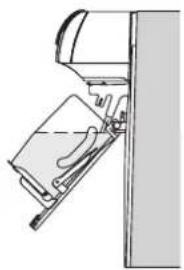
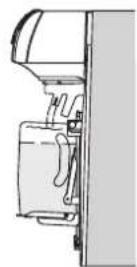
[b] STOPPING AUTOMATIC DISPENSING
IMPORTANT
If power failure occurs during the dispensing operation and the operation panel unit is lifted up, do not pull it down by force after power supply is resumed, but contact your dealer/supplier.
If the display shows an error code (E_, turn off the power supply and turn it back on. If the display still shows the error code, contact your dealer/supplier.
To stop the automatic dispensing operation halfway through:
1) Press the stop button. The platform stops at that position. When the stop button is pressed again, the platform goes back to the original position.
2) If the dispensing operation does not stop with the stop button pressed, lift up the operation panel unit. The beer tap lever comes off the operation panel unit and goes back to the closed position. If beer still keeps running, move the lever back and forth.
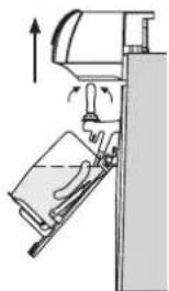
CAUTION
To reduce the risk of injury, do not put your fingers into the bottom opening of the operation panel unit while it is lifted up.
3) Close the keg coupler attached to the beer keg. See "II. 3. [d] REPLACING BEER KEG".
To stop the automatic dispensing operation in case of power failure or error:
Follow steps 2) and 3) above.
[c] MANUAL DISPENSING
1) Lift up the operation panel unit slowly until it locks into place. The display shows "OFF".
2) To dispense beer, pull the beer tap lever quickly toward you until it stops. To avoid excessive foaming, do not pull the lever slowly or stop it halfway. Release the lever to stop beer.
3) To dispense foam, push the beer tap lever quickly away from you until it stops. To avoid liquid foam, do not stop the lever halfway. Release the lever to stop foam.
Note: When the beer tap lever is pushed during manual dispensing operation, the valve shaft end comes out. Be careful not to hit the mug on the shaft.
![Hoshizaki BEERMATIC DualTap DBF-AS65WE-EU-HC - [c] MANUAL DISPENSING - 1](/content/2026/04/704246/images/009f09aa7fde7f1018477cb9d3b5450bd57eff460664ac1ba864386af1370624.jpg)
![Hoshizaki BEERMATIC DualTap DBF-AS65WE-EU-HC - [c] MANUAL DISPENSING - 2](/content/2026/04/704246/images/6b66848b518164918bfd6e7ffacca318027878c28641ee492a1e70179484d243.jpg)
![Hoshizaki BEERMATIC DualTap DBF-AS65WE-EU-HC - [c] MANUAL DISPENSING - 3](/content/2026/04/704246/images/2b4365014667d4834feafff53fc19679a8fbafe943dafc48cdd3678f1b01bd5b.jpg)
Valve Shaft End
[d] SWITCHING TO AUTOMATIC DISPENSING MODE
1) Hold the bottom of the operation panel unit and pull the front handle toward you to unlock.
2) Pull down the operation panel unit until it stops to cover up the beer tap lever. The dispense lamp comes on.
CAUTION
To prevent injury, do not hold the cross-marked part but hold the curved surface at the front side when pulling down the operation panel unit.
To avoid damage, do not pull down the operation panel unit by force without unlocking the handle.
7. SOLD OUT SENSOR
When the beer keg becomes empty, the unit automatically detects the condition and stops the dispensing operation. The sold out lamp lights up, and the dispense button becomes unavailable.
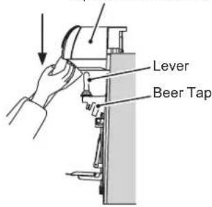
Operation Panel Unit
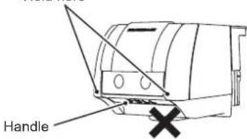
Hold here
IMPORTANT
The sold out sensor is factory set to "0: Setting A (mainly beer)".
In the manual dispensing mode, the unit will not stop dispensing even if the sold out lamp lights up. Be careful with the keg level while dispensing beer.
When the sold out lamp lights up, replace the beer keg. See "3. [d] REPLACING BEER KEG" and "4. [b] LEADING BEER TO TAP".
8. END OF DISPENSING OPERATION
1) Close the beer circuit.
Rotary type: Turn the keg coupler handle counterclockwise until it stops.
Vertical type: Unlock and lift the keg coupler handle all the way up.
IMPORTANT
When the keg coupler on the keg is closed, gas may stay inside the beer circuit. To prevent excessive foaming or improper dispensing actions, lead beer into the beer circuit until gas comes out of the beer tap before starting operation on the following day. See "4. [b] LEADING BEER TO TAP".
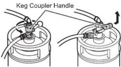
Rotary Type Vertical Type
2) Flush the beer circuit according to "III. 2. BEER CIRCUIT (DAILY)".
3) Turn the regulator adjust dial to set the pressure to "0" (MPa).
4) Close the main valve of the CO2 gas cylinder by turning it clockwise.
Note: To prevent too much CO2 gas entering the beer keg, always close the main valve of the CO2 gas cylinder at the end of dispensing operation.
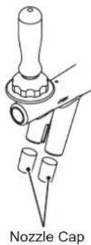
5) Wipe off moisture from the end of the beer tap nozzles. Clean and attach the nozzle caps (accessory).
Note: Always attach the accessory nozzle caps at the end of dispensing operation or during periods of non-use to prevent entrance of insects or dirt into the beer tap nozzles.
9. SHUT DOWN
[a] SHUT DOWN
1) Check that the key coupler is closed. See "8.END OF DISPENSING OPERATION".
Note: If the keg coupler is open, the floor can be wet in the event of beer leakage.
![Hoshizaki BEERMATIC DualTap DBF-AS65WE-EU-HC - [a] SHUT DOWN - 1](/content/2026/04/704246/images/7858ae7eb1b947288c83dd3b427d59d0b80cb5ed93eb2a933f1b6606dbd88b46.jpg)
Nozzle Cap
2) Unplug the unit. The refrigeration unit and agitator motor stop.
[b] DRAINING WATER TANK
HYGIENE
When shutting down the dispenser for more than a week, drain the water tank to prevent water contamination.
Note: It takes a few days after shutdown to melt ice in the water tank. Before draining the water tank, shut down the unit in advance and check that ice has melted in the water tank. Otherwise, it cannot be drained completely.
1) Remove the drain pan (accessory). See "III. 3. DRAIN PAN AND GRILLE" (DAILY).
2) Place a bucket with a capacity of at least 35L in front of the unit. Remove the plug from the drain outlet to drain the water tank.
3) After draining the water tank, remove the top cover to dry the water tank interior.
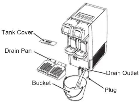
III. MAINTENANCE
| ▲WARNING |
| Before carrying out any cleaning or maintenance operations, unplug the dispenser from the electrical supply network. |
| This appliance must not be cleaned by use of a water jet. |
| NOTICE |
| To prevent possible damage, do not clean the plastic parts with water above 40°C or in a dishwasher. |
| Use a neutral cleaner for daily maintenance and invert soap ( benzalkonium chloride) for sanitization. |
| To prevent damage to the painted or plastic surfaces, do not use thinner, benzine, alcohol, petroleum, soap powder, polishing powder, alkaline detergent, acid, scrub brush, and especially cleanser for use on fans and cooking ranges. Also, to prevent corrosion, do not use a chlorine bleach (sodium hypochlorite). |
| When using chemical wipes, follow the manufacturer's instructions. |
| Use a clean cloth with clean hands. |
| More frequent cleaning may be required in some cases. |
| ▲HYGIENE |
| When using invert soap or sodium hypochlorite, thoroughly read and understand the instructions provided to prevent potential health problems. |
| At the end of dispensing operation, clean the beer circuit every day to prevent contamination. |
| Clean your hands before handling or cleaning the parts. |
1. BASIC CLEANING
1) Wash your hands.
2) Prepare clean cloths.
3) Unplug the unit.
4) Mix about 10~mL of 10% invert soap (benzalkonium chloride) solution in 1 L of warm water (30 to 40^ ). Damp a dry cloth to wipe the parts clean.
5) After 3 minutes, wipe off any remaining soap with a cloth containing cold or warm water. Then, wipe dry with a clean cloth.
IMPORTANT
Any remaining cleaning solution may damage the metal and plastic surfaces.
To remove dirt buildup, use a neutral cleaner and rinse with tap water.
2. BEER CIRCUIT (DAILY)
To flush the beer circuit, use the cleaning tank specified by the beer company. Follow the instructions provided with the cleaning tank.
1) Press the flush button on the operation panel. Check that the flush lamp lights up.
2) Close the beer circuit.
Rotary type: Turn the keg coupler handle counterclockwise until it stops.
Vertical type: Unlock and lift the keg coupler handle all the way up.
3) Turn the regulator adjust dial to set the pressure to "0" (MPa).
4) Close the main valve of the CO2 gas cylinder by turning it clockwise.
5) Press the liquid button to dispense the beer left in the circuit.
6) When no more beer comes out, press the stop button.
7) Turn the keg coupler counterclockwise to remove it from the beer keg.
8) Wash the cleaning tank thoroughly and fill it with tap water.
Note: If the cleaning tank is not clean, the beer circuit will be contaminated.
9) Turn the key coupler clockwise to attach it to the cleaning tank.
Note: Wash the joint between the keg coupler and cleaning tank if it is not clean.
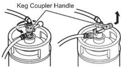
Rotary Type Vertical Type
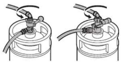
Rotary Type Vertical Type
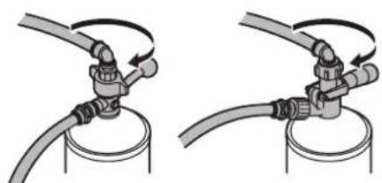
Rotary Type Vertical Type
10) Check that the beer tap lever is in the closed (normal) position. Open the main valve of the CO2 gas cylinder by turning it counterclockwise a few times.
11) Turn the regulator adjust dial to set the pressure to "0.15" (MPa).
12) Open the beer circuit.
Rotary type: Turn the keg coupler handle clockwise until it stops.
Vertical type: Push down the keg coupler handle until it locks in place.
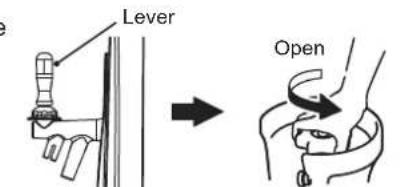
Closed Position
CO2 Gas Cylinder
Note: If the cleaning tank is provided with a siphon tube, lay the cleaning tank with the ferrule at the top. If not, lay the cleaning tank with the ferrule at the bottom.
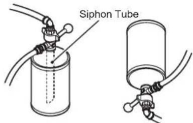
Provided Not provided
13) Remove the platforms and drain pan and place a bucket under the beer tap.
14) Press the liquid button to dispense water from the liquid nozzle. Repeat a few times until no more water comes out. Then, press the foam button to dispense water from the foam nozzle. Repeat a few times until no more water comes out.
15) When no more water comes out of the nozzle, keep the beer tap lever in the open position and turn the regulator adjust dial to set the pressure to "0" (MPa).
16) Close the main valve of the CO2 gas cylinder by turning it clockwise.
17) When CO2 gas stops coming out of the nozzle, press the stop button to close the beer tap.
18) Close the beer circuit. Rotary type: Turn the keg coupler handle counterclockwise until it stops. Vertical type: Unlock and lift the keg coupler handle all the way up.
19) Turn the keg coupler counterclockwise to remove it from the cleaning tank.
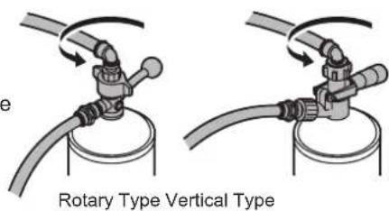
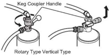
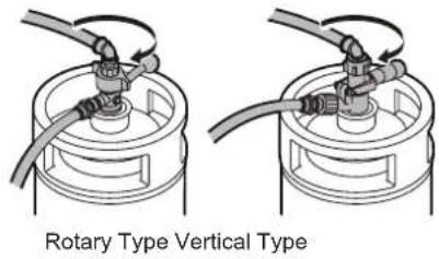
20) Turn the keg coupler clockwise to attach it to the beer keg.
Note: Wash the joint between the keg coupler and beer keg if it is not clean.
21) Wash the cleaning tank interior thoroughly, turn the tank upside down to dry, and cap it tightly for storage.
22) Set the platform on the arms.
23) Press the flush button on the operation panel. Check that the flush lamp goes off and the sold out lamp comes on.
24) Wipe off moisture from the end of the beer tap nozzles. Clean and attach the nozzle caps (accessory).
Note: Always attach the accessory nozzle caps at the end of dispensing operation or during periods of non-use to prevent entrance of insects or dirt into the beer tap nozzles.
3. DRAIN PAN AND GRILLE (DAILY)
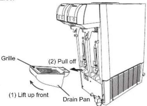
1) Lift up the front of the drain pan and pull it off toward you.
Note: Be careful not to spill water and beer in the drain pan.
2) Wash the grille and drain pan with tap water.
3) Set the grille on the drain pan and fit the drain pan by pushing it securely into the drain pan support.
4. PLATFORM (DAILY)
1) Slightly lift up and remove the platform from the arms.
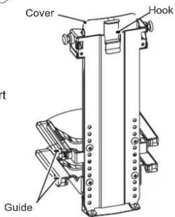
2) Lift the cover off the platform.
3) Wash the cover and platform with tap water. Use warm water and a cloth or sponge to remove dirt buildup in the gaps.
4) Insert the cover into the platform until it hooks up.
5) Refit the platform to the arms.
| NOTICE |
| Handle the platform with care. If it is dropped and damaged, proper mug size detection may not be available. |
| If the platform is damaged, contact your dealer/supplier. |
5. CLEANING BEER CIRCUIT WITH SPONGE (WEEKLY)
To flush the beer circuit, use the cleaning tank specified by the beer company. Follow the instructions provided with the cleaning tank.
1) Follow the steps of "2. BEER CIRCUIT (DAILY)".
2) Lift up the operation panel unit slowly until it locks into place.
3) Turn the union nut clockwise to remove the beer tap.
NOTICE
Handle the beer tap with care and do not drop it.
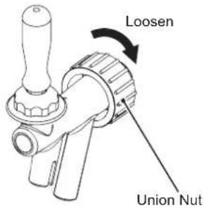
4) Loosen the cap nut to disassemble the beer tap. Fit the valve shaft in the opposite direction and tighten the cap nut.
| NOTICE |
| Attach the valve shaft in the opposite direction to prevent the cleaning sponge from clogging the beer tap. |
| Handle the valve shaft with care. If it is deformed or damaged, beer may leak. |
| Handle the beer tap lever with care and do not drop it. |
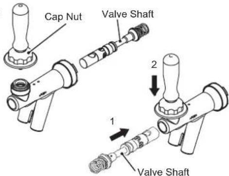
5) Attach the beer tap on the unit by turning the union nut counterclockwise.
6) Remove the accessory drain pan and grille. See "3. DRAIN PAN AND GRILLE (DAILY)".
7) Place a bucket under the beer tap to receive cleaning water.
8) Turn the keg coupler counterclockwise to remove it from the beer keg.
9) Remove the quick beer hose joint from the keg coupler, and put only one cleaning sponge (accessory) into the joint.
NOTICE
Use of more than one cleaning sponge or a non-accessory sponge can cause clogging of the beer circuit. In such case, contact your dealer/supplier.
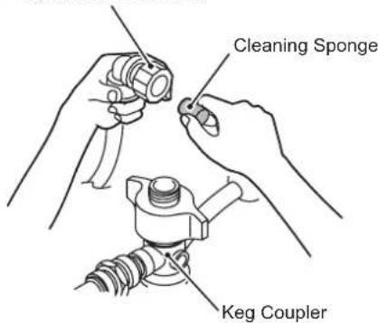
Quick Beer Hose Joint
10) Attach the quick beer hose joint to the keg coupler.
11) Wash the cleaning tank thoroughly and fill it with tap water.
Note: If the cleaning tank is not clean, the beer circuit will be contaminated.
12) Turn the keg coupler clockwise to attach it to the cleaning tank.
Note: Wash the joint between the keg coupler and cleaning tank if it is not clean.
13) Open the main valve of the CO2 gas cylinder by turning it counterclockwise a few times.
14) Turn the regulator adjust dial to set the pressure to "0.15" (MPa).
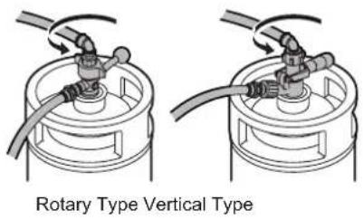
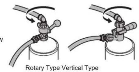
15) Open the beer circuit.
Rotary type: Turn the keg coupler handle clockwise until it stops.
Vertical type: Push down the keg coupler handle until it locks in place.
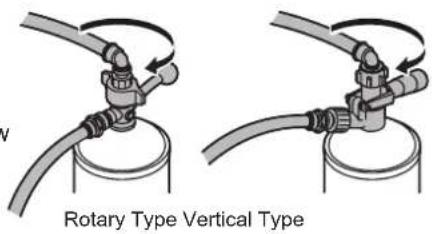
Note: If the cleaning tank is provided with a siphon tube, lay the cleaning tank with the ferrule at the top. If not, lay the cleaning tank with the ferrule at the bottom.
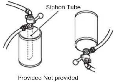
16) Wait until the cleaning sponge and water come out of the liquid nozzle.
17) Turn the regulator adjust dial to set the pressure to "0" (MPa).
18) Close the main valve of the CO2 gas cylinder by turning it clockwise.
19) Check that CO2 gas stops coming out of the nozzle.
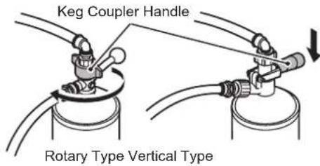
20) Close the beer circuit.
Rotary type: Turn the keg coupler handle counterclockwise until it stops.
Vertical type: Unlock and lift the keg coupler handle all the way up.
21) Turn the keg coupler counterclockwise to remove it from the cleaning tank.
22) Thoroughly wash and dry the cleaning sponge and store it for later use.
23) Repeat the above steps 9) to 22) until clear water comes out of the beer tap.
Note: Receive the water in a mug or glass to check its cleanness. Repeat a few times until water becomes clear.
24) Turn the union nut clockwise to remove the beer tap.
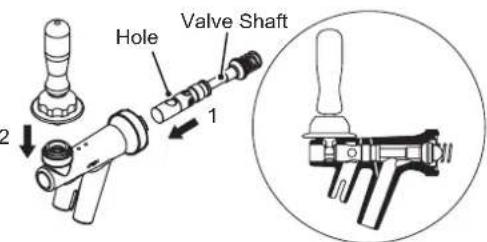
25) Loosen the cap nut to disassemble the beer tap. Fit the valve shaft in the original (normal) direction while aligning the holes in the beer tap and valve shaft (larger hole facing up), and tighten the cap nut.
Note: Assemble the beer tap correctly, or beer cannot be dispensed properly.
26) Attach the beer tap on the unit by turning the union nut counterclockwise.
27) Wash the cleaning tank interior thoroughly, turn the tank upside down to dry, and cap it tightly for storage.
28) Hold the bottom of the operation panel unit and pull the front handle toward you to unlock. Pull down the operation panel unit until it stops to cover up the beer tap lever.
Note: To prevent malfunction, do not pull down the operation panel unit with the beer tap removed.

28) Hold the bottom of the operation panel unit and pull the front handle toward you to unlock. Pull down the operation panel unit until it stops to cover up the beer tap lever. Note: To prevent malfunction, do not pull down the operation panel unit with the beer tap removed.
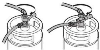
29) Turn the keg coupler clockwise to attach it to the beer keg.
Note: Wash the joint between the keg coupler and beer keg if it is not clean.
Rotary Type Vertical Type
30) Wipe off moisture from the end of the beer tap nozzles. Clean and attach the nozzle caps (accessory).
Note: Always attach the accessory nozzle caps at the end of dispensing operation or during periods of non-use to prevent entrance of insects or dirt into the beer tap nozzles.
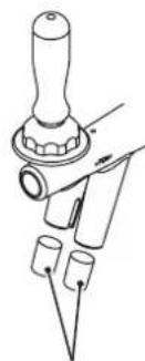
Nozzle Cap
6. DISASSEMBLY AND CLEANING OF BEER TAP (WEEKLY)
1) Follow the steps 1) to 7) of "2. BEER CIRCUIT (DAILY)".
2) Lift up the operation panel unit slowly until it clicks and locks into place.
3) Turn the union nut clockwise to remove the beer tap.
4) Loosen the cap nut to disassemble the beer tap.
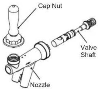
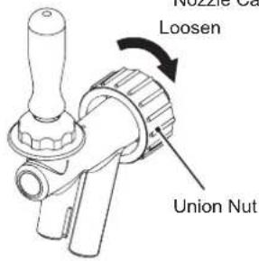
5) Use a neutral dishwashing detergent and the accessory brush to clean inside the beer tap and valve shaft.
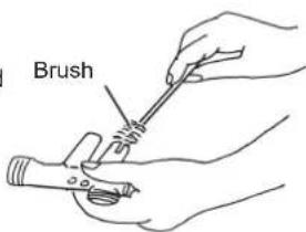
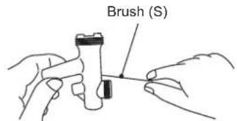
6) Use the accessory brush (S) to clean the two small holes in the beer tap.
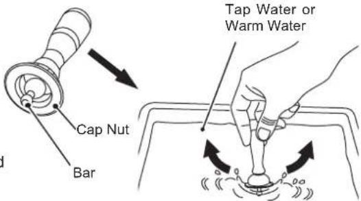
7) Soak the bar and cap nut interior in tap water or warm water and shake them to remove dirt.
8) Rinse the parts thoroughly with tap water.
9) Fit the valve shaft in the original (normal) direction while aligning the holes in the beer tap and valve shaft (larger hole facing up), and tighten the cap nut.
Note: Assemble the beer tap correctly, or beer cannot be dispensed properly.
10) Hold the bottom of the operation panel unit and pull the front handle toward you to unlock. Pull down the operation panel unit until it stops to cover up the beer tap lever.
7. KEG COUPLER (WEEKLY)
Follow the instructions provided by the beer company to clean the keg coupler.
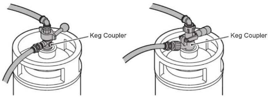
Rotary Type Vertical Type
8. EXTERIOR (WEEKLY)
The exterior is easily contaminated. Always keep it clean.
| NOTICE |
| To prevent damage, do not use any cleaner other than a neutral cleaner on the plastic exterior. |
1) Wipe with a cloth containing warm water and a neutral cleaner.
2) Use a damp cloth to wipe off any remaining cleaner.
9. AIR FILTER (BIWEEKLY)
| NOTICE |
| Keep the air filter clean to ensure proper operation. |
| Do not operate the unit with the air filter removed. Dust may enter the unit resulting in failure. |
| IMPORTANT |
| The air filter must be cleaned as required by the installation condition. |
1) Pull out the air filter.
2) Wash the air filter with cold water or warm water containing a neutral cleaner.
Note: Be careful not to damage the mesh.
3) Dry the air filter well in the shade.
4) Refit the air filter.
IV. INSPECTION
1. COOLING WATER AND ELECTRODE (BIANNUALLY)
| IMPORTANT |
| Replace the cooling water and check the electrode for cleanliness twice a year. |
1) Unplug the unit. The refrigeration unit and agitator motor stop.
2) Remove the top cover.
3) Check that the water level is above the water level mark inside the water tank.
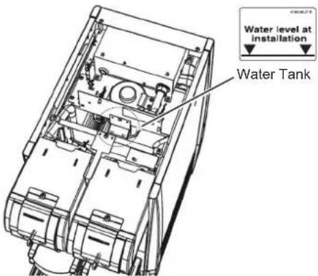
4) Drain the water tank. See "II. 9. [b] DRAINING WATER TANK".
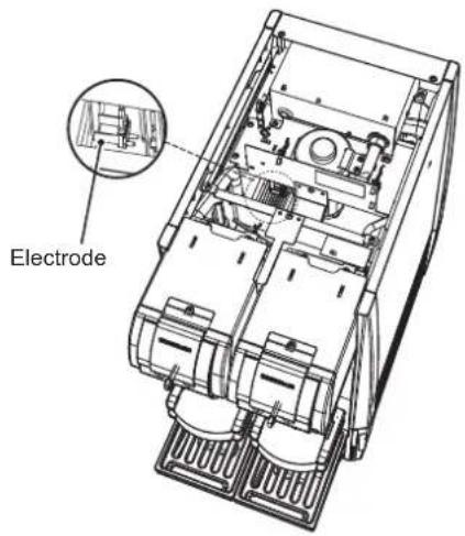
5) Check if the electrode is clean.
NOTICE
If the electrode has turned brown or black or is not clean, contact your dealer/ supplier.
6) Fill the water tank. See "II. 2. FILLING WATER TANK".
7) Plug in the unit. The refrigeration unit and agitator motor start.
IMPORTANT
It takes about 8 to 13 hours from startup to completion of ice storage in the water tank. Dispensed beer may not be cold enough until ice production completes.
Check the gas and beer hoses for damage, deformation, and water leak marks (stains). If any problem is found, contact your dealer/supplier.
3. ATTACHMENT PLUG AND POWER CORD (ANNUALLY / BIANNUALLY)
WARNING
Check periodically that the attachment plug blades and their vicinity are free of dust and that the attachment plug is securely plugged into the receptacle. Dusty blades or loose connection may cause electric shock or fire.
Do not damage the power cord. It should not be additionally processed, jerked, bundled, weighed down or caught in. It could cause electric shock or fire.
The unit must have a separate power supply. Branching off the power cord, using an extension cord, or sharing a single power supply with other appliances may result in electric shock, heat generation or fire.
Check that:
- The attachment plug blades and their vicinity and the receptacle are free of dust. Clean them if necessary.
- The attachment plug and power cord are not damaged, weighed down or caught in.
- The attachment plug is plugged into a separate receptacle.
V. OTHER INFORMATION
1. PREPARED THE DISPENSER FOR LONG STORAGE
WARNING
When shutting down the dispenser for more than a week, unplug the unit.
1) Drain the water tank according to "II. 9. [b] DRAINING WATER TANK".
2) Carry out the following maintenance procedures to clean and drain the beer circuit and to keep the unit clean:
III. 5. CLEANING BEER CIRCUIT WITH SPONGE (WEEKLY)
- DISASSEMBLY AND CLEANING OF BEER TAP (WEEKLY)
- KEG COUPLER (WEEKLY)
- EXTERIOR (WEEKLY)
- AIR FILTER (BIWEEKLY)
3) When restarting the unit, follow the procedures below:
II. 1. CLEANING BEER CIRCUIT
- FILLING WATER TANK
- CHECKS BEFORE OPERATION (DAILY)
- START UP
- SETTING LIQUID AND FOAM AMOUNTS
- DISPENSING
- SOLD OUT SENSOR
- END OF DISPENSING OPERATION
2. BEFORE CALLING FOR SERVICE
If the dispenser does not work properly, check the following table before calling for service. If the problem still exists, turn off the power switch (earth leakage breaker) and contact your dealer/supplier.
Do not attempt to repair the unit by yourself. Only qualified personnel may repair the unit.
| Problem Possible Cause Remedy | ||
| Unit will not start. | The unit is unplugged. Plug in. | |
| The fuse is blown out. Contact your dealer/supplier. | ||
| Power failure. Wait until power is resumed. | ||
| Beer is not cold. | No ice in the water tank. Wait until ice is produced. | |
| Less than 8 to 13 hours after the power switch (earth leakage breaker) is turned on. | Ice production takes 8 to 13 hours depending on ambient and water temperatures. Wait for 8 to 13 hours before dispensing beer. | |
| Ambient temperature is above \(30^{\circ}\mathrm{C}\). Ventilate | with a fan to lower ambient temperature. | |
| No cooling water in the water tank. Fill the water tank. See "II. 2. FILLING WATER TANK". | ||
| The air inlet or outlet is blocked or not clean. Clean or unblock. See "III. 9. AIR FILTER (BIWEEKLY)" . | ||
| No beer is dispensed. | The beer keg is empty. Replace with a new keg. See "II. 3. [d] REPLACING BEER KEG". | |
| The CO2 gas cylinder is empty. | Replace with a new cylinder. See "II. 3. [b] REPLACING CO2 GAS CYLINDER". | |
| The main valve of CO2 gas cylinder is closed. | Open. | |
| The regulator is set to "0". | Adjust the regulator to a proper pressure. See "II. 3. [b] REPLACING CO2 GAS CYLINDER". | |
| The keg coupler is not attached to the beer keg correctly. | Check and correct. See "II. 3. [d] REPLACING BEER KEG". | |
| The keg coupler handle is closed. | Open the beer circuit. See "II. 3. [d] REPLACING BEER KEG". | |
| Beer cloggs the beer tap and the lever cannot move smoothly. | Disassemble and clean the beer tap. See "III. 6. DISASSEMBLY AND CLEANING OF BEER TAP (WEEKLY)" . | |
| Abnormal noise. | Operation sound of the refrigeration unit or condenser fan motor. | No problem. |
| The foundation is not firm. | Contact your dealer/supplier. | |
| The foundation is not level. | Contact your dealer/supplier. | |
| Something is touching the unit. | Keep it away from the unit. | |
| Too much foam. | The beer keg has just been shaken or moved. | Wait until beer in the keg settles down. |
| The beer keg is almost empty. Replace with a new keg. See "II. 3. [d] REPLACING BEER KEG". | ||
| The CO2 gas cylinder is left open after the end of dispensing operation. | Close the cylinder every day at the end of dispensing operation. See "II. 8. END OF DISPENSING OPERATION". | |
| The regulator is not set to a proper pressure. Adjust the regulator to a proper pressure. See "II. 3. [b] REPLACING CO2 GAS CYLINDER". | ||
| Mug or glass is not clean. Clean. | ||
| The mug or glass temperature is too high. Follow the instructions of the beer company. | ||
| The beer tap or beer circuit is not clean. Clean. See "III. 2. BEER CIRCUIT (DAILY)" | ||
| No ice in the water tank. Wait until ice is produced. | ||
| The gas hose is reversely connected. Reconnect. | ||
| Excessive foam overflows. | The mug size or platform used is different from that at the time of setting. | Set a mug of the same size on the same platform as used at the time of setting. |
| Too little or too much liquid or foam. | The regulator adjust dial has been turned after liquid amount adjustment. | Readjust the CO2 gas pressure and the liquid and foam amounts. |
| Sold out lamp lights up while keg is not empty. | The CO2 gas pressure is not properly adjusted. | Readjust the CO2 gas pressure and the liquid and foam amounts. |
| Foam is in the hose. See "Too much foam" above. | ||
3. DISPOSAL
Comply with local regulations regarding disposal of this appliance and its refrigerant gas.
Correct disposal of this product:
This marking indicates that this product should not be disposed with other household wastes throughout the EU. To prevent possible harm to the environment or human health from uncontrolled waste disposal, recycle it responsibly to promote the sustainable reuse of material resources. To return your used device, use the return and collection systems or contact the retailer where the product was purchased. They can take this product for environmental safe recycling.
4. WARRANTY
Hoshizaki warrants to the original owner/user that all Hoshizaki branded products shall be free of defects in material and/or workmanship for the duration of the "warranty period". The warranty shall be effective for one year from the date of installation. Hoshizaki's liability under the terms of the warranty are limited and shall exclude routine servicing, cleaning, essential maintenance and/or repairs occasioned by misuse and installations not in accordance with Hoshizaki guidelines.
Warranty repairs should be completed by an approved Hoshizaki dealer or service agency using genuine Hoshizaki components.
To obtain full details of your warranty and approved service agency, please contact your dealer/supplier, or the nearest Hoshizaki Service office:
Hoshizaki UK -UK, Ireland
TEL: +44 845 456 0585
FAX: +44 132 283 8331
uksales@hoshizaki.uk
Hoshizaki Middle East - Middle East
TEL: +971 48 876 612
FAX: +971 48 876 613
sales@hoshizaki.ae
Hoshizaki Deutschland - Germany, Switzerland, Austria, Poland, Czech Republic, Slovakia
TEL: +49 5121 697370
FAX: +49 5121 6973719
Hoshizaki Benelux - Netherlands, Belgium, Luxembourg
TEL: +31 85 018 83 70
info@hoshizaki.nl
Hoshizaki France - France
TEL: +33 148 63 93 80
FAX: +33 1 48 63 93 88
info@hoshizaki.fr
Hoshizaki Iberia - Spain, Portugal
TEL: +34 93 478 09 52
FAX: +34 93 478 08 00
info@hoshizaki.es
Hoshizaki Italia - Italy
TEL: +39 344 0616467
TEL: +39 348 3022156
info@hoshizaki.it
Hoshizaki Europe B.V. - all other countries within Europe and
Africa
TEL: +31 20 6918499
FAX: +31 20 6918768
sales@hoshizaki.nl
SPECIFICATIONS
| Model DBF-AS65WE-EU-HC | |
| Power Supply 1 phase 220 - 240V 50Hz | |
| Dispensing Capacity 65 L (30°C to 8°C / 4 hrs) | |
| Ice Making Time 11 hrs (Initial Cooling Water Temp 25°C) | |
| Ice Storage Capacity 12 L | |
| Dimensions 367mm(W) x 674mm(D) x 764mm(H) | |
| Refrigerant R600a, 80g | |
| Insulation Foam Blowing Agent HFO-1233zd(E) | |
| Weight Net: 50kg (Gross: 77kg) | |
| Ambient Temp 5 - 32°C |
INFORMATIONS IMPORTANTES RELATIVES A LA SECURITE
V. INFORMATIONS DIVERSES
1. PREPARATION DE LA TIREUSE EN VUE D'UN STOCKAGE PROLONGE
AVERAGEMENT
Hoshizaki France - France
TEL:+33148639380
FAX: +33 148 63 93 88
info@hoshizaki.fr
Hoshizaki Italia - Italie
TEL: +39 344 0616467
TEL: +39 348 3022156
info@hoshizaki.it
Hoshizaki Iberia - Espagne, Portugal
TEL:+34934780952
FAX:+34934780800
info@hoshizaki.es
[b] CO2-PATRONE AUSTAUSCHEN
[d] BIERFASS WECHSELN
WARNING
[b] KOELWATERTOEVOER
WAARSCHUWING
EU DECLARATION OF CONFORMITY
Manufacturer: HOSHIZAKI CORPORATION
Address: 3-16, Minamiyakata, Sakae, Toyoake, Aichi, 470-1194, Japan
This declaration of conformity is issued under the sole responsibility of the manufacturer and, if applicable, his authorized representative.
Product: HOSHIZAKI Automatic Draft Beer Dispenser
Model(s): DBF-AS65WE-EU, DBF-AS65WE-EU-HC
The object of the declaration described above is in conformity with the relevant Union harmonisation legislation.
References to the relevant harmonised standards used or references to the other technical specifications in relation to which conformity is declared;
Electromagnetic Compatibility Directive 2014/30/EU
Machinery Directive 2006/42/EC
RoHS Directive 2011/65/EU, (EU) 2015/863
Emission EN 55014-1:2017
EN 61000-3-2:2019
EN 61000-3-3:2013
Immunity EN 55014-2:2015
MD EN 60335-1:2012
EN 60335-2-24:2010
EN 60335-2-75: 2004
EN ISO 12100:2010
EMF EN 62233:2008
RoHS EN IEC 63000:2018
Authorized Representative:
Address:
Amsterdam, 21 May 2021
Place and date of issue
Hoshizaki Europe B.V.
Netherlands Signature:
Kazuya Jinno
Managing Director
Hoshizaki Europe B.V
UK DECLARATION OF CONFORMITY
Manufacturer: HOSHIZAKI CORPORATION
Address: 3-16, Minamiyakata, Sakae, Toyoake, Aichi, 470-1194, Japan
This declaration of conformity is issued under the sole responsibility of the manufacturer and, if applicable, his authorized representative.
Product: HOSHIZAKI Automatic Draft Beer Dispenser
Model(s): DBF-AS65WE-EU, DBF-AS65WE-EU-HC
The object of the declaration described above is in conformity with the relevant Union harmonisation legislation.
References to the relevant harmonised standards used or references to the other technical specifications in relation to which conformity is declared;
Electromagnetic Compatibility Regulations 2016
Supply of Machinery (Safety) Regulations 2008
RoHS Regulations 2012
Emission EN 55014-1:2017
EN 61000-3-2:2019
EN 61000-3-3:2013
Immunity EN 55014-2:2015
MD EN 60335-1:2012
EN 60335-2-24:2010
EN 60335-2-75: 2004
EN ISO 12100:2010
EMF EN 62233:2008
RoHS EN IEC 63000:2018
Authorized Representative: Hoshizaki Europe B.V.
Address: The Technology Centre London Road, Swanley, Kent BR8 7AG,
The United Kingdom
Swanley, 17 May 2021
Place and date of issue Simon Frost
Branch Manager UK and Ireland
Hoshizaki Europe B.V
- FRANCAIS
- DEUTSCH
- IMPORTANT SAFETY INFORMATION
- INSTALLATION INSTRUCTIONS
- CONSTRUCTION
- NOTICE
- ACCESSORIES
- 3.UNPACKING
- LOCATION
- INSTALLATION
- [a] DISPENSER
- [b] DRAIN PAN
- [c] PLATFORM ADJUSTMENT
- ELECTRICAL CONNECTIONS
- GAS AND BEER CIRCUIT CONNECTIONS
- [a] CO2 GAS CYLINDER
- CO2 Gas Hose
- Quick Gas Hose Joint
- Beer Hose
- [c] CHECKS AFTER CONNECTIONS
- CHECKS AFTER INSTALLATION
- SOLD OUT SENSOR SETTING ("U07")
- USER SETTINGS
- OPERATING INSTRUCTIONS
- CLEANING BEER CIRCUIT
- FILLING WATER TANK
- [a] HOW TO MAKE COOLING WATER
- Electric conductivity (E.C.) of cooling water for water tank
- How to make cooling water with 100 - 300~ S / cm of E.C.
- Step 1
- Step 2
- [b] COOLING WATER SUPPLY
- WARNING
- CHECKS BEFORE OPERATION (DAILY)
- [a] CHECKING CO2 GAS CYLINDER
- [b] REPLACING CO2 GAS CYLINDER
- [c] CHECKING BEER KEG
- [d] REPLACING BEER KEG
- START UP
- IMPORTANT
- [a] SWITCHING MODE
- [b] LEADING BEER TO TAP
- SETTING LIQUID AND FOAM AMOUNTS
- CAUTION
- [a] LARGER MUG SETTING
- [b] SMALLER MUG SETTING
- DISPENSING
- [a] AUTOMATIC DISPENSING
- [b] STOPPING AUTOMATIC DISPENSING
- [c] MANUAL DISPENSING
- [d] SWITCHING TO AUTOMATIC DISPENSING MODE
- SOLD OUT SENSOR
- END OF DISPENSING OPERATION
- SHUT DOWN
- [a] SHUT DOWN
- [b] DRAINING WATER TANK
- HYGIENE
- MAINTENANCE
- BASIC CLEANING
- BEER CIRCUIT (DAILY)
- DRAIN PAN AND GRILLE (DAILY)
- PLATFORM (DAILY)
- CLEANING BEER CIRCUIT WITH SPONGE (WEEKLY)
- DISASSEMBLY AND CLEANING OF BEER TAP (WEEKLY)
- KEG COUPLER (WEEKLY)
- EXTERIOR (WEEKLY)
- AIR FILTER (BIWEEKLY)
- INSPECTION
- COOLING WATER AND ELECTRODE (BIANNUALLY)
- ATTACHMENT PLUG AND POWER CORD (ANNUALLY / BIANNUALLY)
- OTHER INFORMATION
- PREPARED THE DISPENSER FOR LONG STORAGE
- BEFORE CALLING FOR SERVICE
- DISPOSAL
- WARRANTY
- INFORMATIONS IMPORTANTES RELATIVES A LA SECURITE
- INFORMATIONS DIVERSES
- PREPARATION DE LA TIREUSE EN VUE D'UN STOCKAGE PROLONGE
- AVERAGEMENT
- [b] CO2-PATRONE AUSTAUSCHEN
- [d] BIERFASS WECHSELN
- [b] KOELWATERTOEVOER
- WAARSCHUWING
- EU DECLARATION OF CONFORMITY
- UK DECLARATION OF CONFORMITY
Brand : Hoshizaki
Model : BEERMATIC DualTap DBF-AS65WE-EU-HC
Category : Beer dispenser