IQ18LBV - Blower MURRAY - Free user manual and instructions
Find the device manual for free IQ18LBV MURRAY in PDF.

User questions about IQ18LBV MURRAY
0 question about this device. Answer the ones you know or ask your own.
Ask a new question about this device
Download the instructions for your Blower in PDF format for free! Find your manual IQ18LBV - MURRAY and take your electronic device back in hand. On this page are published all the documents necessary for the use of your device. IQ18LBV by MURRAY.
USER MANUAL IQ18LBV MURRAY
WARNING! Read this manual before operating your product.
Not for Reproduction
Languages
English (Original Instructions) 1
Croatian 15
Czech 29
Danish 43
Dutch 57
Finnish 71
French 85
German 99
Hungarian 113
Italian 127
Norwegian 141
Polish 155
Portuguese 169
Slovakian 183
Slovenian 197
Spanish 211
Swedish 225
Details
Thank you for purchasing your Murray product. Murray prides itself in the quality and performance of all its products. This instruction manual will aid in the assembly, safe operation and maintenance of your product. Please read the following warnings to ensure safety and the long life of your product.

WARNING
Do not attempt to operate this product until you have read thoroughly and understood completely all instructions, safety rules, etc, contained in this manual. Failure to comply may result in accidents involving electric shock, fire, and/or serious personal injury.
INTENDED USE
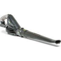
This Blower Vac is intended for the blowing and vacuuming of leaves, grass clippings and other similar garden debris in domestic use. Do not use for stones, bricks, broken glass etc. Do not use as an air/gas extraction unit.
Do not use the product for any task, except for that which it is intended.
Warning Symbols & Meanings

Warning!

Read the directions for use before operating the machine.

Wear safety goggles and ear protection that meet safety standards.

Wear sturdy, non-slip footwear.

Wear safety gloves.

Do not use machine in wet conditions, protect the machine from rain and damp.
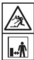
Be careful of objects being thrown out! Ensure bystanders are kept at least 50" (15m) away & stop the machine if approached.

Keep hands, loose hairs and loose clothing away from blower fan.
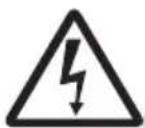
Beware of electric shock hazard when charging.

Read the directions before carrying out any maintenance work.

Wait for all components of the machine to completely stop & remove the batteries.
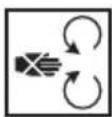
Keep hands clear of moving parts.
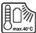
Ambient temperature 40°C Max.

Do not throw into water.

Keep away from heat and/or open flame.
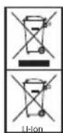
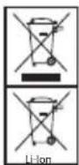
Should NOT be disposed of with household items.
Batteries contain Li-ion. Contact local authority to find out how to dispose of batteries appropriately.
Table of Contents

Features & Definitions
Features & supplied items 3

Safety & Handling
General safety 4
Safety instruction for blower vac 5

Assembly Procedures
Unpacking 5
Blower tube assembly 6
Vacuum bag fitment 6
Installing the carry harness 6
Battery fitment 7

Operating Instructions
Adjusting the front handle 8
Starting & stopping 8
Using operate switch 8
Operation 9
Emptying vacuum bag 10
Clearing blower tube/Impellor 10

Maintenance & Care
Cleaning 11
Storage 11
Product disposal 11
Emergency contact 11
Maintenance chart 12
Service 12

Troubleshooting
Troubleshooting 12

Technical Specifications
Product specifications 13
NOTE: WARRANTY DETAILS ARE NOT WRITTEN WITHIN THIS OPERATOR'S MANUAL. REFER TO OTHER DOCUMENTS SUPPLIED WITH THIS MACHINE FOR WARRANTY DETAILS.
Features & Supplied Items
- Motor Housing
- Front Handle
- Rear Handle
- Speed Dial
- Carry Harness Hook
- Operate Switch
- Vacuum Bag *
- Vacuum Bag Release Switch
- Upper Tube Assembly
-
Lower Tube Assembly *
-
Retaining Screw *
- Carry Harness *
- Vacuum Inlet
- Blower Outlet
- Wheels
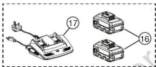
- Batteries
- Battery Charger
- Screwdriver **
- Blower VAC Manual & Warranty **
- B&S Battery & Charger Manual and Warranty **
text_image
17 16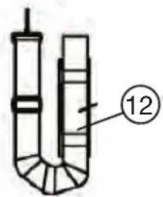
text_image
12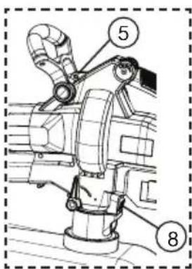
text_image
Technical diagram of a mechanical assembly with numbered components labeled 5 and 8
text_image
Technical diagram of a spray gun with numbered components and an inset showing internal parts.
Do not operate the product if any component is missing or damaged. Have any missing or damaged components repaired or replaced.
NOTE: '*' marked items are supplied loose and require assembly before use. Refer to 'Assembly Procedure' section of this manual for more details.
NOTE: ‘**’ marked items are not shown in the figure above.
NOTE: Batteries and charger are not included with console purchase.
General Safety
- Carefully read all instructions on the machine and in the manual before attempting to assemble and operate the machine. Keep this manual in a safe place for future reference, and consult it regularly. Ensure other users read this manual and are aware of the product safety risks.
- The machine should be operated only with a genuine Briggs & Stratton batteries. When using battery operated machine basic safety precaution should always be followed to reduce the risk of leaking batteries and personal injury.
- Become familiar with all controls and their proper operation before using the machine. Know how to stop the machine and how to disengage the power in an emergency.
• Always wear a face mask or a dust mask when operating the machine in a dusty environment.
- Always wear appropriate clothing & do not wear loose clothing (or jewellery etc) that can get caught in moving parts.
- Do not operate this machine in bare feet, or while wearing sandals or lightweight (e.g. canvas shoes) Wear long trousers & heavy shoes.
- Do not operate the machine while under the influence of alcohol or drugs.
- Stay alert & do not operate the machine when you are tired. Pay attention to what you are doing and ensure others are aware of your task intentions before commencing.
- Avoid using the machine in dangerous environments. Only use the machine in daylight or in good artificial light.
- Do not use the machine in a rush. Always walk & never run with the machine. Do not overreach and keep balance at all times. Be careful while working on slopes.
- Before inspecting, adjusting, servicing or cleaning the machine, always stop & remove both the batteries.
- If the machine starts to vibrate excessively, discontinue use until the machine has been inspected and assessed. Having a machine assessed for vibration problems generally reduces the risk for injury or product failure.
- Only store the machine indoors in a dry & secure location. Keep the machine out of reach of children.
• Always maintain the machine according to the maintenance section of this manual.
- Do not use the machine in rain or wet conditions. Water entering the power tool may increase the risk of shock. Wet conditions may decrease the vacuuming performance.
- Never allow children, persons with reduced physical, sensory or mental capabilities or lack of experience and knowledge or people unfamiliar with these instructions to use the machine. Local regulations may restrict the age of the operator.
- Use extreme care when approaching blind corners, doorways, shrubs, trees, or other objects that may obscure your view & the path of the machine.
- Do not use the machine near hot ash, combustible materials or immerse in liquids. This may cause fire hazard, serious injury or product damage.
- Do not put any object into ventilation grills. Do not use with any openings blocked, keep openings free from anything that may reduce air flow.
- Do not point the machine in the direction of people or pets.
- The fan will continue to move for a short time after unit is turned off. Keep all objects at a safe distance from moving parts.
- Never operate the machine while people, especially children, or pets are nearby.
- Do not use the machine if the power switch or speed dial is not working. Any machine that cannot be controlled with the switch is dangerous and must be repaired first before use.
Safety Instructions for Blower VAC
- Avoid accidental starting as it may result in injury. Please ensure the speed dial is in off ('0') position before connecting the batteries. Do not carry the Blower Vac with your finger on speed dial.
- Do not operate the Blower Vac without fitting the lower tube assembly. Turn the Blower Vac off and remove both the batteries when lower tube assembly is disassembled for maintenance.
- Do not manually place the objects into the Blower Vac tube while operating as this can seriously damage the unit or harm the user. Keep both hands on the handles while using.
- Do not attempt to remove material or hold material to be vacuumed during operation. Switch off and remove the batteries before clearing the jammed material from the Blower Vac tube.
- Do not pick the Blower Vac unit from the tube or attempt to carry the unit from the tube.
- Never direct the Blower Vac or blow debris towards bystanders or pets. The operator is responsible for accidents or hazards occurring to other people or their property.
- Do not use the Blower Vac in vacuum operation without the vacuum bag fitted.
- Blower Vac unit is different from household vacuum unit and the vacuumed content is shredded /mulched.
- Check regularly that all the screws are tight.
- Do not allow the Blower Vac to pick up any burning or smouldering materials like ashes, cigarette butts etc.
- Do not attempt to pick up breakable objects like glass, plastics, bone-china etc.
NOTE: Refer to B&S battery & charger manual to understand the risks and safe use of batteries and chargers. Ensure other users read the manual and are aware of the product safety risks.
ASSEMBLY PROCEDURES
Unpacking
The Blower is supplied with some components not assembled. To assemble these, proceed as follows:
- Carefully remove the product and any accessories from the box. Make sure that all items listed on page 3 are included.
- Inspect the product carefully to make sure no breakage or damage occurred during shipping.
NOTE: Batteries and charger are not included with consoles and can be brought separately.

WARNING
If any parts are damaged or missing do not operate this product until the parts are replaced. Using a product with damaged or missing parts could result in serious personal injury.
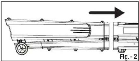
Blower Tube Assembly
NOTE: Refer Fig. (2) & (3).
- Push the Lower Tube Assembly into the Upper Tube Assembly by aligning as shown in Fig. (2).
- The tubes will fit together into each other.
- Fit the Retaining Screw (A) and tighten it using a screw driver to secure the upper and lower tubes together.
- To disassemble, repeat the steps in reverse order.
natural_image
Technical line drawing of a mechanical cart or trailer with directional arrow indicating motion (no text or symbols)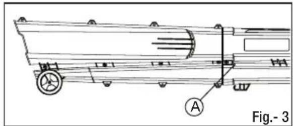
natural_image
Technical line drawing of a mechanical vehicle with labeled component A, no readable text or symbols present
Do not operate the Blower Vac without fitting the Lower Tube Assembly. Turn the blower vac OFF and remove both the batteries when lower tube assembly is disassembled for clearing the bloackage or maintenance.
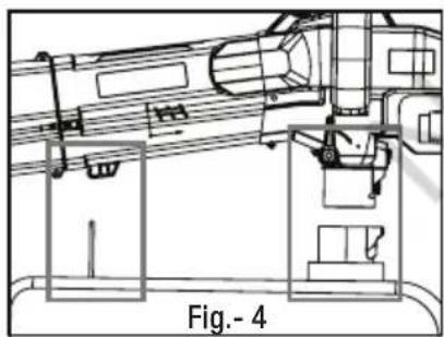
Vacuum Bag Fitment
natural_image
Technical line drawing of a crane lifting equipment, labeled Fig.-4 (no text or symbols on the diagram itself)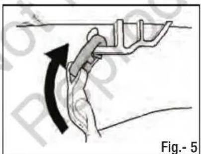
natural_image
Diagram of a hand gripping a mechanical component with an arrow indicating rotation (no text or symbols)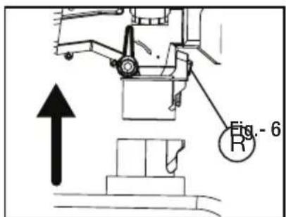
text_image
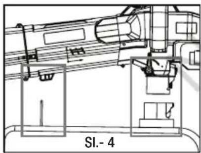
Fig.- 6- Attach the clip on the vacuum bag to the hook underneath the tube as shown in Fig 5.
- Insert the inlet connector on the vacuum bag until it locks into the bottom of the main body.
- To release the inlet connector and vacuum bag, press the vacuum bag release switch (R).
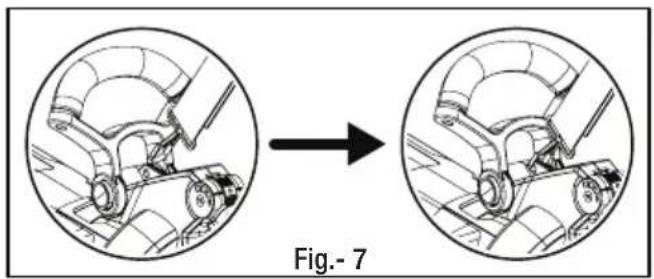
Installing the Carry Harness
- Carry harness is supplied loose and can be used if required.
- To install, insert the harness clip in the hole behind the front handle as shown in Fig-7.
natural_image
Diagram showing a vehicle wheel assembly before and after transformation, labeled Fig.-7 (no text or symbols on the diagram itself)ASSEMBLY PROCEDURES
Battery Fitment
INSTALLING THE BATTERIES
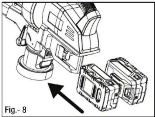
- Align the raised rib on the batteries with grooves in the blower vac battery port and push the batteries in as shown in Fig.- 8.
- Make sure the latch on bottom of the batteries snaps (click) in place.
- Make sure the batteries are secured in the blower vac before beginning operation.
natural_image
Technical line drawing of a mechanical device with two components, one showing an arrow indicating assembly or operation (no text or symbols present)REMOVING THE BATTERIES
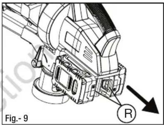
- Turn the blower vac off.
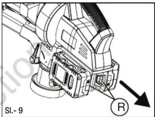
- Press and hold the Battery Release Latch ('R') at the bottom of the batteries as shown in Fig.-9.
- Remove the batteries from the blower vac.
text_image
Fig.- 9 R
Before fitting the batteries, ensure that the blower vac is speed dial is in the '0' OFF position to prevent accidental starting.

Improper installation of the batteries can cause damage to internal components and may fall from product whilst in use causing product damage or personal injury.

Refer to Briggs & Stratton 18V Battery & Charger instruction manual for further information realting to battery & charger safety, use, servicing and storage.
Adjusting the Front Handle
Front handle of the blower vac unit can be rotated at any desired angle to suit individual comfort.
- To adjust, press and hold the two buttons 'A', simultaneously. Ref Fig.- 10.
- Rotate the handle and release the button 'A'. If done correctly, front handle will snap (click) into the new position.

Before operating, make sure the front handle is secured properly and buttons 'A' comes back to its original position.

text_image
Fig.- 10 AStarting & Stopping
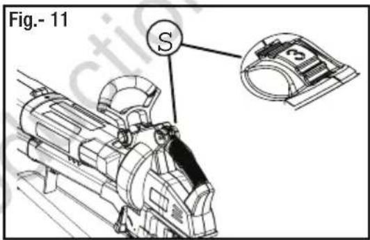
The speed dial is located at the front of the rear handle and is used to switch the blower vac ON and OFF. It is also used as a controller for the speed of the motor. Refer Fig. 11 & 12.
• Install both the batteries.
- Roll the variable speed dial ('S') forward to 1 to start the blower vac.
- Blower Vac unit has variable speed settings. Rolling the speed dial ('S') forward from 1 to 5 will increase the speed of the motor to maximum.
- Roll the variable speed dial ('S') backward to slow the speed or roll it to '0' positon to stop the blower vac.
- Remove the batteries to ensure the blower is not turned on accidentally.
text_image
Fig.- 11 S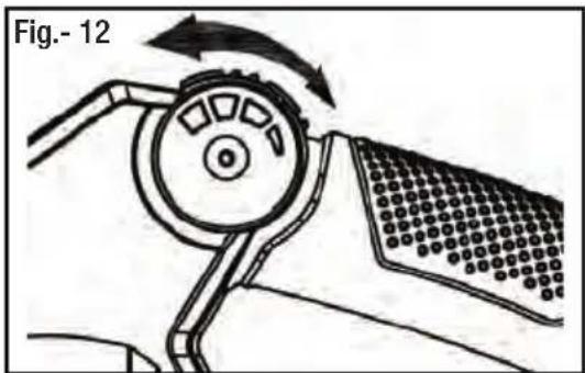
natural_image
Diagram of a mechanical device with rotating components and directional arrows (no text or symbols)Using Operate Switch
Operate switch is used to switch between the blower mode and vacuum mode. Refer Fig.- 13.
- Pushing the function lever to position 'A' engages the vacuum mode of operation.
- Pushing the function lever to position 'B' engages the blower mode.
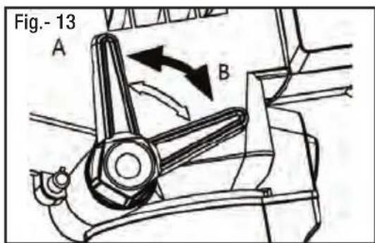
text_image
Fig.- 13 A BOperation


IMPORTANT TIPS / SAFETY WARNINGS
- Assure the unit is not directed at anybody or any loose debris before starting the unit.
- Verify that the unit is in good working condition. Make sure the lower tube assembly and vacuum bag are fitted and secure.
- Beware of your surroundings when operating the blower vac. Watch out for children, pets, open windows and blow debris safely away.
- When using the blower vac, do not let the vacuum bag rub on the ground. If the bag rubs on the ground, it will quickly wear a hole in the bag. This damage is not covered under warranty.
- Never cover air vents. Keep them free from obstructions and debris. They must always remain clear for proper motor cooling and optimum performance.
- Wear appropriate clothing. To avoid serious personal injury, do not wear loose fitting clothing or articles such as scarves, strings, chains, ties etc., that could get drawn into the air vents. To make sure long hair does not get drawn into the air vents, tie long hair back.
BLOWING MODE
- Hold the blower vac firmly with one hand on the rear handle and the other hand on the front handle.
- Sweep from side to side with the blower outlet 5-10cm above the ground or floor. Slowly advance, keeping the accumulated pile of debris in front of you.
- Most dry blowing operations are better suited at low speeds. High speed blowing is best for blowing heavier items like large debris or gravel.
NOTE: Blower Vac can be used in blowing mode with or without the vacuum bag fitted.
VACUUM MODE
- Vacuum mode is used to collect or mulch the debris in the vacuum bag. Items such as small leaves and twigs will be mulched as they pass through the fan housing.
- With a firm hold on the unit, use a gap of 5-10cm from the ground and use a sweeping action to collect the debris.
- Move easily from one pile of debris to the next by gliding on the wheels.
- As the bag fills, suction power will decrease. When this happens, switch the blower off, remove the batteries and empty the vacuum bag.
- For longer bag life and optimal performance, empty the vacuum bag frequently.

Do not use the blower vac unit in vacuum mode without fitting the vacuum bag first. It may result in serious injury.
Emptying Vacuum Bag

Before removing the vacuum bag for emptying debris, switch OFF the blower vac and remove the batteries.

Wear a dust mask when emptying the vacuum bag.
- To empty the vacuum bag ('B'), use the zipper on the rounded section of the vacuum bag.
- Make sure the vacuum bag ('B') zip is fully closed before restarting the blower vac.
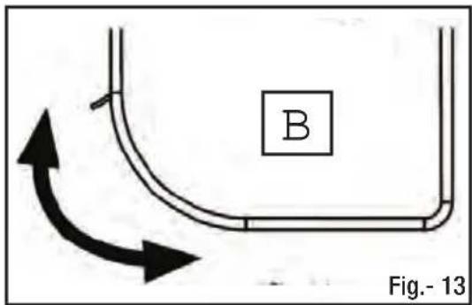
text_image
B Fig.- 13Clearing Blocked Tube / Impellar
During the vacuum operation, certain objects such as cloth, rope or large diameter sticks may obstruct the fan and block the motor.
If an obstruction occurs:
- Switch the blower off and remove both the batteries.
- Remove the lower tube assembly and the vacuum bag. Refer 'Blower Tube Assembly' section under Assembly procedures to understand how to remove the lower tube assembly.
- Using protective gloves, carefully remove the material blocking the tube or impeller blades.
- Rotate the impellar blades by hand to ensure the blockage is competely cleared.
- Reinstall the lower tube assembly and the vacuum bag.
- Reinstall the batteries.

Before clearing the blocked tube or impellar blade, switch OFF the blower vac and remove both the batteries. Accidental starting of blower vac when clearing the blockage may result in serious personal injury or amputation.

Wear safety gloves for protection.
Cleaning

To avoid serious personal injury, always turn the blower vac off and remove the batteries before cleaning or servicing.
Do not use solvents, strong detergents, certain aromatic oils such as pine and lemon when cleaning plastic parts. Chemicals can damage, weaken or destroy plastic component which may result in serious personal injury.
- Clean the unit using a damp cloth with a mild detergent. Do not immerse the machine or any part of it in water.
- Moisture can cause a shock hazard. Wipe off any moisture with a soft dry cloth & ensure the machine is dry before use.
- Use a small brush or vacuum cleaner to clean the air vents on the product. Keep the air vents free of obstructions.
Storing
- Ensure the batteries are removed before storage.
- Store the machine indoors, in a cool, dry place, out of the reach of children.
- Do not store it next to corrosive materials, such as fertilizer or fuel.
Product Disposal
CORRECT DISPOSAL OF THE PRODUCT
Waste electrical products should not be disposed of with household waste. Please recycle where facilities exist. Check with your local authority or retailer for recycling advice. The battery contains material which is hazardous to you and the environment. It must be removed and disposed of separately at a facility that accepts lithium-ion batteries.

Refer to Briggs & Stratton 18V Battery & Charger manual for further information relating to battery and charger disposal.

CORRECT DISPOSAL OF THE PACKAGING
The packaging consists of cardboard and correspondingly marked plastics that can be recycled. Make these materials available for recycling.
Information about the residual risks that remain despite the inherit safe design measures, safeguarding and complementary protective measures adopted.
Emergency Contact
In the rare case a battery is damaged & any of the contents leaks or comes into contact with a persons skin, eyes, or is ingested, follow the first aid instructions inside the battery & charger manual. Seek further medical attention immediately.
Maintenance Chart
| Features Requirements | Before use | After use | Recharging | Monthly | Yearly | If damaged | As required | |
| Whole unit | Visual inspection | ● | ● | ● | ||||
| Variable Speed Dial | Check operation | ● | ||||||
| Blower housing | Check & clean | ● | ● | |||||
| Air inlet | Check & clean | ● | ||||||
| Tube | Check & clean | ● | ● | |||||
| Vacuum Bag | Check & empty | ● | ● | ● | ||||
| All accessible fasteners | Check & re-tighten. | ● | ● | |||||
Service
Servicing requires extreme care and knowledge and should be performed only by a qualified service technician. For service we suggest you return the product to your authorized service centre. When servicing, use only genuine replacement parts.
- Keep the machine dry, clean, and free of oil and grease.
- In order to reduce the risk of fire, keep the motor free of grass, leaves, debris build-up.
- Keep all nuts, bolts, and screws tight in order to be sure that the equipment is in safe working condition.
- Never tamper with safety devices. Check them regularly for proper operation.
NOTE: Refer to warranty card supplied with this product for service contact details.
TROUBLESHOOTING

Troubleshooting
| Fault Possible | Cause Possible Solution | |
| Blower Vac won't start. | 1. Batteries not installed properly.2. Batteries are not charged.3. Blower Vac unit is faulty. | 1. Ensure that the batteries are properly installed in the product.2. Charge the batteries fully.3. Have the unit replaced or repaired by an authorized service centre. |
| Blower Vac is not operating at full capacity. | 1. Tube or Impellar fan is blocked.2. Vacuum bag is full of debris. | 1. Check and clear the blockage following the procedure in the manual.2. Remove the vacuum bag and empty the debris. |
| Unit stops while running. | 1. Batteries exhausted. 1. Recharge the batteries. |
Product Specifications
| Description TWIN 18V BLOWER VAC | ||
| Function Blow Vacuum | ||
| Motor Type Brushless Motor | ||
| Motor Specification 36V DC | ||
| Motor Wattage 600 W | ||
| No Load Speed 5000~13000 RPM | ||
| Maximum Motor Speed 13000 RPM | ||
| Maximum Air Velocity 240 km/h 50 km/h | ||
| Vacuum Bag Volume 45 L | ||
| Shredding / Mulching Ratio | 10:1 | |
| Product Weight (No Batteries) | 3.35 Kg | |
| Sound Pressure Level | 86 dB(A), K_PA = 3 dB(A) | 86 dB(A), K_PA = 3 dB(A) |
| Sound Power Level (Measured) | 99.5 dB(A) | 101.9 dB(A) |
| Sound Power Level (Guaranteed) | Lwa: 105 dB (A) | |
| Vibration Total Value (Max) | <2.5 m/s2, K= 1.5 m/s2 | |
WARNING
- That the declared vibration total value has been measured in accordance with a standard test method and may be used for comparing one tool with another.
- That the declared vibration total value may also be used in a preliminary assessment of exposure.
- That the vibration emission during actual use of the power tool can differ from the declared total value depending on the ways in which the tool is used and of the need to identify safety measures to protect the operator that are based on an estimation of exposure in the actual conditions of use (taking account of all parts of the operating cycle such as the times when the tool is switched off and when it is running idle in addition to the trigger time).
Pojedinosti
Zahvaljujemo na kupovini Murray proizvoda. Murray se ponosi kvalitetom i performansama svojih proizvoda. Ovaj korisnički priručnik pomaže pri montaži, sigurnom radu i održavanju vašeg proizvoda. Molimo da pročitate sljedeća upozorenja kako bi osigurali sigurnost i dugi vijek trajanja vašeg proizvoda.

UPOZORENJE
text_image
Technical diagram of a mechanical assembly with numbered components labeled 5 and 8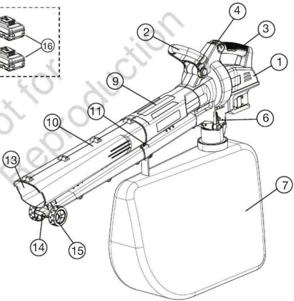
text_image
Technical diagram of a spray gun with numbered components and an inset showing internal parts with numbers 1 through 16.
natural_image
Technical line drawing of a mechanical cart or trailer with directional arrow and label 'Sl.- 2' (no readable text or symbols)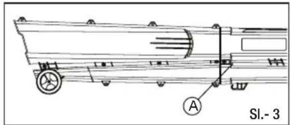
text_image
Sl.- 3 A
Bez prethodnog postavljanja donje cijevi ne palite Vac puhač.
Vac puhač ISKLJUČITE i izvadite baterije ako se donja cijev rastavlja za potrebe vađenja zaglavljenih predmeta ili održavanje.
Postavljanje vrećice za usisavač
natural_image
Technical line drawing of a mechanical assembly with no visible text or symbols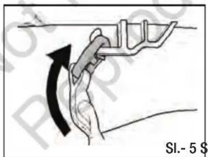
text_image
SI.- 5 $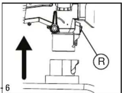
text_image
R 6- Na torbu usisavača pričvrstite spojnicu na kuku ispod cijevi, kao što je prikazano na SI. 5
- Ulazni konektor na vakumskoj torbi umetnite dok se ne priključi na donji dio uređaja.
- Za otpuštanje ulaznog konektora i vakumske torbe, pritisnite prekidač za otpuštanje vakumske torbe (R).
natural_image
Technical line drawing of a mechanical device with an arrow indicating assembly or operation (no text or symbols present)UKLANJANJE BATERIJA
- Isključite vac puhač.
- Pritisnite i držite spojku za otpuštanje baterije('R') na donjem dijelu baterija kao što je prikazano na SI. - 9.
- Uklonite bateriju iz vac puhača.
text_image
SI.- 9 R
text_image
Technical diagram of a mechanical assembly with numbered components labeled 5 and 8
text_image
a habijecky 1 2 3 4 16 9 11 10 6 7 13 14 15
natural_image
Technical line drawing of a mechanical component with directional arrow and label 'Obr. - 2' (no readable text or symbols)
text_image
Obr. - 3 A
natural_image
Technical line drawing of a crane lifting equipment (no text or symbols)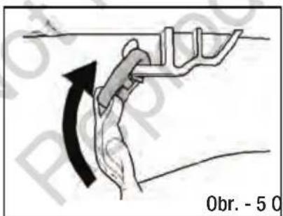
text_image
Obr. - 5 0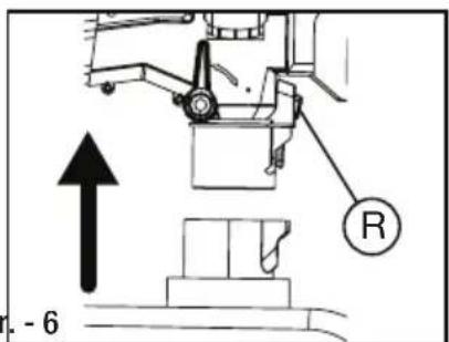
text_image
Technical diagram showing mechanical assembly with labeled component 'R' and directional arrow indicating motion or forcenatural_image
Diagram showing a vehicle wheel assembly before and after transformation, labeled 'Obr. - 7' (no text or symbols on diagram itself)natural_image
Technical line drawing of a mechanical device with an arrow indicating assembly or operation (no text or symbols present)ODSTRANĚNÍ BATERIÍ
text_image
Obr. - 9 R
text_image
Obr. - 10 Atext_image
Obr. - 11 S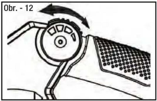
text_image
Obr. - 12Monterings Procedurer
Udpakning 47
text_image
Technical diagram of a mechanical assembly with numbered components labeled 5 and 8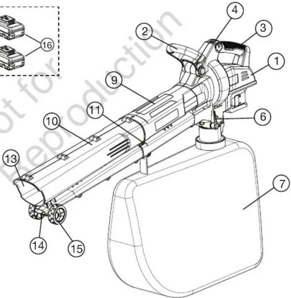
text_image
Technical diagram of a mechanical device with numbered components, including a zoomed-in inset view.
natural_image
Technical line drawing of a mechanical device with directional arrow and figure label (Fig.-2), no readable text or symbols beyond the label.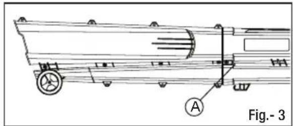
natural_image
Technical line drawing of a mechanical vehicle with labeled component A, no readable text or symbols present
natural_image
Technical line drawing of a crane lifting equipment (no text or symbols)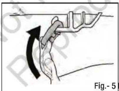
natural_image
Diagram of a hand holding a mechanical component with an arrow indicating rotation (no text or symbols)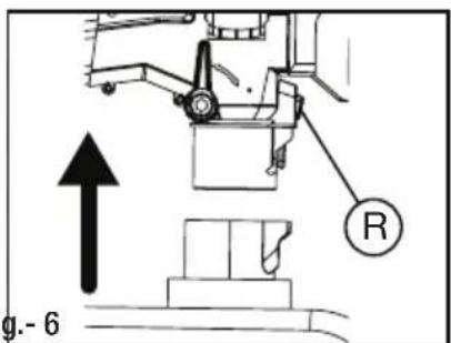
text_image
g.- 6natural_image
Mechanical assembly diagram showing a component being processed from a circular tool, labeled Fig.-7 (no text or symbols on the diagram itself)MONTERINGS PROCEDURER
Batteritilpasning
INSTALLATION AF BATTERIER
natural_image
Technical line drawing of a mechanical device with an arrow indicating assembly or operation (no text or symbols present)FJERNELSE AF BATTERIER
natural_image
Diagram of a mechanical device with rotating arm and textured base, labeled Fig.-12 (no text or symbols on diagram itself)text_image
Technical diagram of a mechanical assembly with numbered components labeled 5 and 8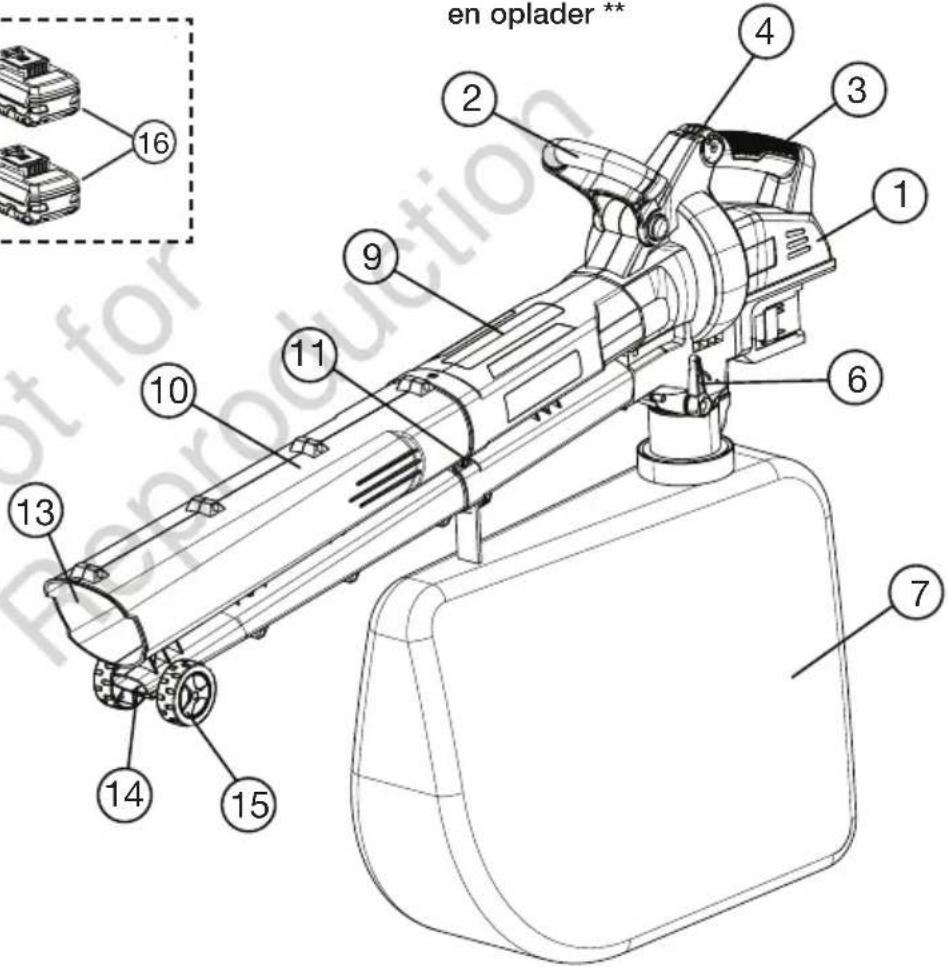
text_image
en oplader** 1 2 3 4 16 9 10 11 6 7 13 14 15
natural_image
Technical line drawing of a mechanical cart or trailer with directional arrow and label 'Afb.-2' (no readable text or symbols)
text_image
Afb.-3
natural_image
Technical line drawing of a mechanical assembly with no visible text or symbols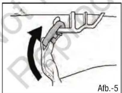
text_image
Afb.-5
text_image
R Afb.-6natural_image
Technical line drawing of a mechanical device with two components and an arrow indicating direction (no text or symbols)text_image
Afb.-10 AIn- en uitschakelen
text_image
Afb.-11 S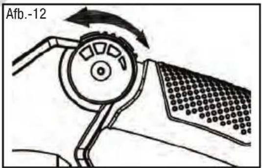
natural_image
Diagram of a mechanical device with rotating components and directional arrows (no text or symbols)Gebruik van
text_image
Technical diagram of a mechanical assembly with numbered components labeled 5 and 8
text_image
Technical diagram of a mechanical device with numbered components, including a zoomed-in inset view.
natural_image
Technical line drawing of a vehicle with a directional arrow and component labels (Kuva-2), no readable text or symbols beyond the label.
text_image
Kuva- 3
natural_image
Technical line drawing of a mechanical assembly with labeled components (Kuva-4), showing no readable text or symbols.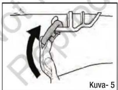
text_image
Kuva- 5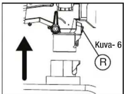
natural_image
Technical line drawing of a Kuva-8 robotic device with mechanical components and an arrow indicating assembly (no text or symbols on the diagram itself)AKKUJEN POISTAMINEN
text_image
Technical diagram of a mechanical assembly with numbered components labeled 5 and 8
text_image
Technical diagram of a mechanical device with numbered components, including a zoomed-in inset for detail.
natural_image
Technical line drawing of a mechanical device with directional arrow and figure label (Fig.-2), no readable text or symbols beyond the label.
natural_image
Technical line drawing of a mechanical vehicle with labeled component A, no readable text or symbols present
natural_image
Technical line drawing of a mechanical assembly with no visible text or symbols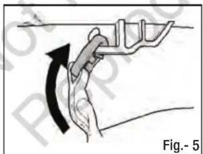
natural_image
Diagram of a hand gripping a mechanical component with an arrow indicating rotation (no text or symbols)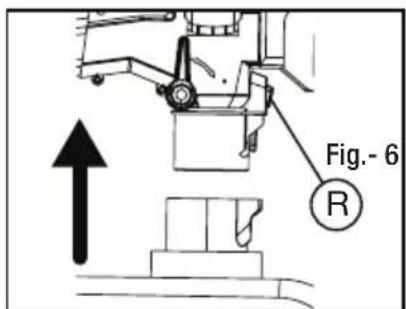
text_image
Fig.- 6 Rnatural_image
Diagram showing a mechanical assembly before and after transformation, labeled Fig.-7 (no text or symbols on the diagram itself)PROCÉDURES DE MONTAGE
Pose de la batterie
INSTALLATION DES BATTERIES
natural_image
Technical line drawing of a mechanical assembly with two components, one showing an arrow indicating direction (no text or symbols)RETRAIT DES BATTERIES
natural_image
Diagram of a mechanical device with rotating components and directional arrows (no text or symbols)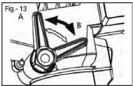
text_image
Fig.- 13 A BINSTRUCTIONS D'UTILISATION
Utilisation


CONSEILS IMPORTANTS / AVERTISSEMENTS DE SÉCURITÉ
ÉLIMINATION CORRECTE DU PRODUIT
text_image
Technical diagram of a mechanical assembly with numbered components labeled 5 and 8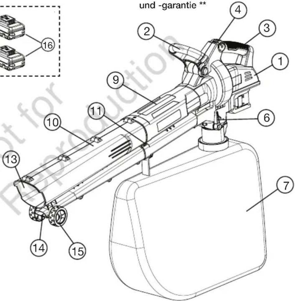
text_image
und -garantie ** 1 2 3 4 16 10 9 11 6 7 15 14 13
natural_image
Technical line drawing of a mechanical cart or trailer with directional arrow and label Abb. 2 (no text or symbols on the diagram itself)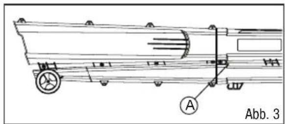
natural_image
Technical line drawing of a vehicle chassis with labeled parts (A), no readable text or symbols beyond label and figure number Abb. 3
natural_image
Technical line drawing of a mechanical assembly with no visible text or symbols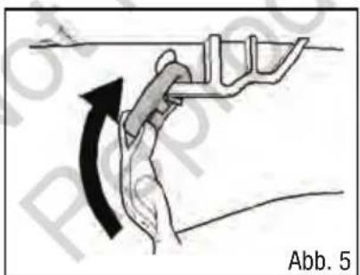
natural_image
Diagram of a hand gripping a mechanical component with an arrow indicating rotation (no text or symbols)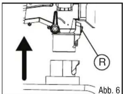
text_image
R Abb. 6natural_image
Diagram showing a vehicle wheel assembly before and after change, labeled Abb. 7 (no text or symbols on the diagram itself)MONTAGE TÄTIGKEITEN
Akkueinbau
EINBAU DER AKKUS
natural_image
Technical line drawing of a mechanical device with two components and an arrow indicating assembly (no text or symbols)AKKUS ENTFERNEN
natural_image
Diagram of a mechanical device with rotating components and directional arrows (no text or symbols)text_image
Technical diagram of a mechanical assembly with numbered components labeled 5 and 8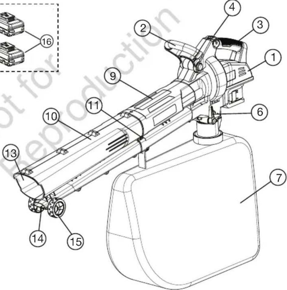
text_image
Technical diagram of a mechanical device with numbered components, including a zoomed-in inset showing parts labeled 1 through 16.
text_image
Technical diagram of a mechanical assembly with numbered components labeled 5 and 8
text_image
Technical diagram of a mechanical device with numbered components, including a zoomed-in inset showing parts labeled 1 through 16.
natural_image
Technical line drawing of a mechanical component with directional arrow and figure label (Fig.-2), no readable text or symbols beyond the label.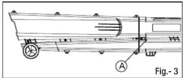
natural_image
Technical line drawing of a truck chassis with labeled components (no text or symbols beyond label)
natural_image
Technical line drawing of a mechanical assembly with no visible text or symbols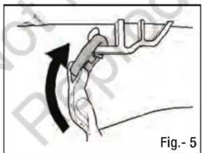
natural_image
Diagram of a hand gripping a mechanical component with an arrow indicating rotation (no text or symbols)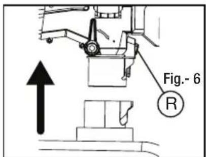
text_image
Fig.- 6 Rnatural_image
Mechanical assembly diagram showing a component being processed from a circular tool, labeled Fig.-7 (no text or symbols on the diagram itself)Batteria
natural_image
Technical line drawing of a mechanical assembly with an arrow indicating direction (no text or symbols)natural_image
Diagram of a mechanical device with rotating components and directional arrows (no text or symbols)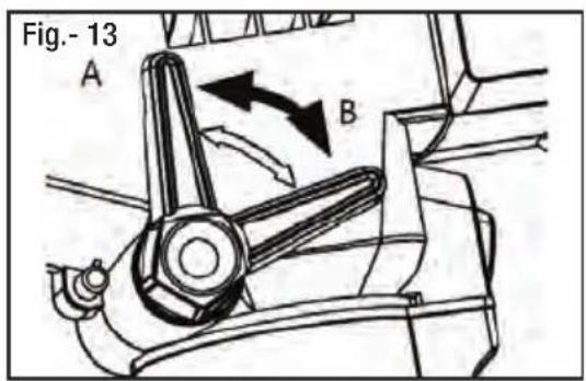
text_image
Fig.- 13 A BFunzionamento


SUGGERIMENTI IMPORTANTI / AVVERTENZE DI SICUREZZA
text_image
Diagram showing two connected devices labeled 17 and 16, with a power plug inserted into the first device.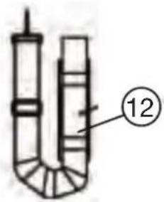
text_image
12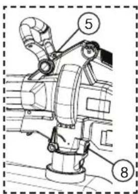
text_image
Technical diagram of a mechanical assembly with numbered components labeled 5 and 8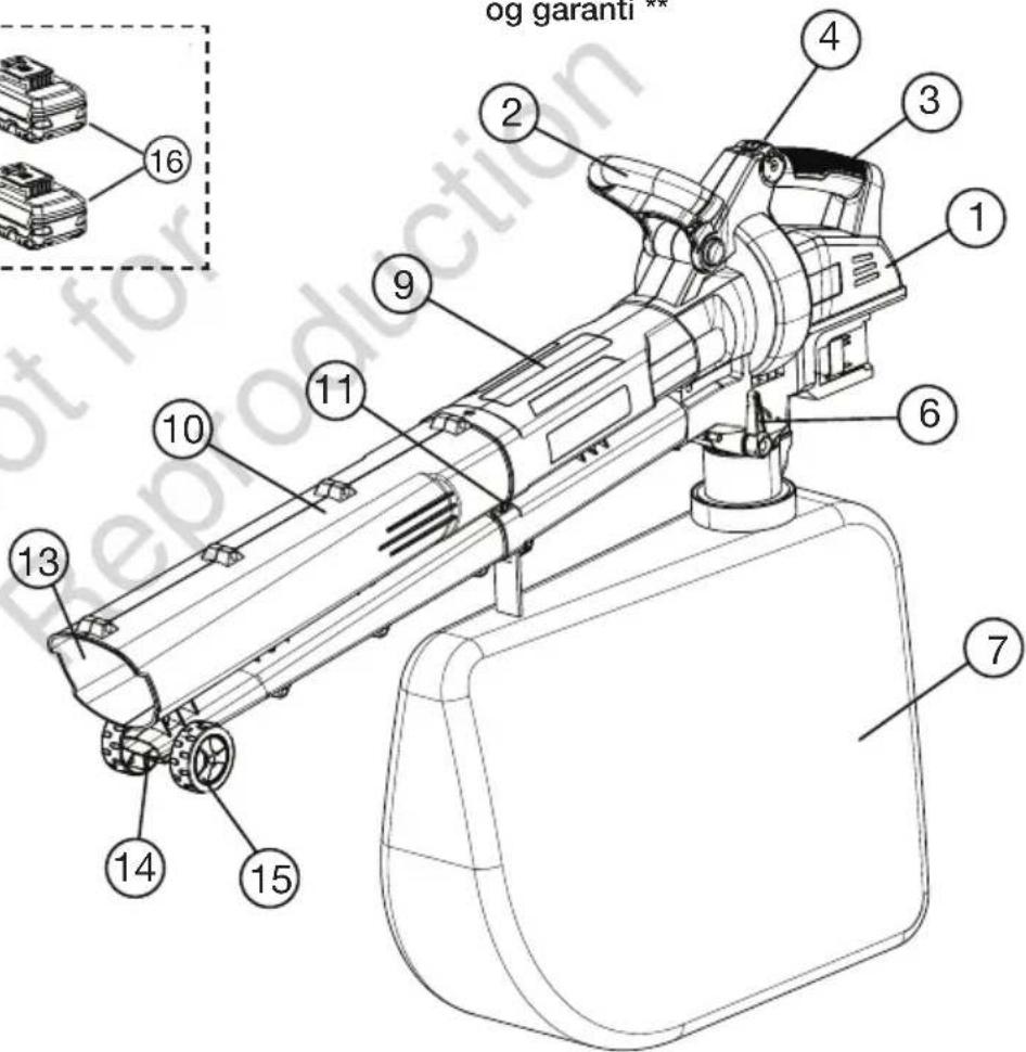
text_image
og garanti * 1 2 3 4 1 16 9 11 10 6 7 13 14 15
natural_image
Technical line drawing of a mechanical cart or trailer with directional arrow indicating motion (no text or symbols)
natural_image
Technical line drawing of a mechanical vehicle with labeled component A, no readable text or symbols present
natural_image
Technical line drawing of a mechanical assembly with no visible text or symbols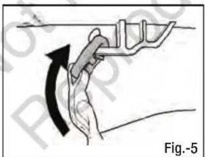
natural_image
Diagram showing a hand gripping a mechanical component with an arrow indicating rotation (no text or symbols present)
text_image
Fig.-6 Rnatural_image
Diagram showing a mechanical assembly before and after transformation, labeled Fig.-7 (no text or symbols on the diagram itself)MONTERINGS PROSEDYRER
natural_image
Technical line drawing of a mechanical device with an arrow indicating assembly or operation (no text or symbols present)FJERNE BATTERIER
text_image
Fig.-10 AStart og stopp
text_image
Fig.-11 S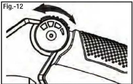
natural_image
Diagram of a mechanical device with rotating components and directional arrows (no text or symbols)text_image
Fig.-13 A BDrift


VIKTIGE TIPS/SIKKERHETSADVARSLER
text_image
B Fig.-13text_image
Technical diagram of a mechanical assembly with numbered components labeled 5 and 8
text_image
Technical diagram of a mechanical device with numbered components, including a zoomed-in inset showing internal parts.
natural_image
Technical line drawing of a mechanical component with an arrow indicating direction, labeled 'Rys. 2' (no text or symbols on the diagram itself)
natural_image
Technical line drawing of a mechanical component with labeled section A (no text or symbols beyond label)
natural_image
Technical line drawing of a mechanical assembly with no visible text or symbols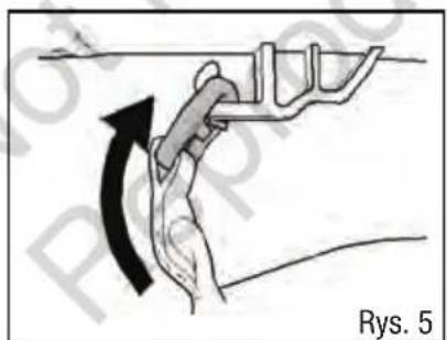
natural_image
Diagram of a hand gripping a mechanical component with an arrow indicating rotation (no text or symbols)
text_image
R Rys. 6natural_image
Diagram showing a mechanical assembly before and after modification, labeled 'Rys. 7' (no text or symbols on the diagram itself)natural_image
Technical line drawing of a mechanical device with an arrow indicating assembly or operation (no text or symbols present)WYJMOWANIE AKUMULATORÓW
natural_image
Diagram of a mechanical device with rotating components and directional arrows (no text or symbols)PRAWIDŁOWA UTYLIZACJA PRODUKTU
text_image
Technical diagram of a mechanical assembly with numbered components labeled 5 and 8NOTA: Consulte as Figs. (2) e (3).
natural_image
Technical line drawing of a mechanical cart or trailer with an arrow indicating direction, labeled 'Fig.-2' (no text or symbols on the diagram itself)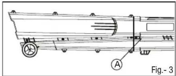
natural_image
Technical line drawing of a mechanical vehicle with labeled component A, no readable text or symbols present
natural_image
Technical line drawing of a crane lifting equipment, labeled Fig.-4 (no text or symbols on the diagram itself)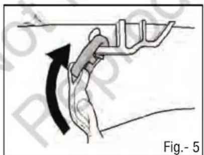
natural_image
Diagram of a hand gripping a car handle with an arrow indicating motion (no text or symbols)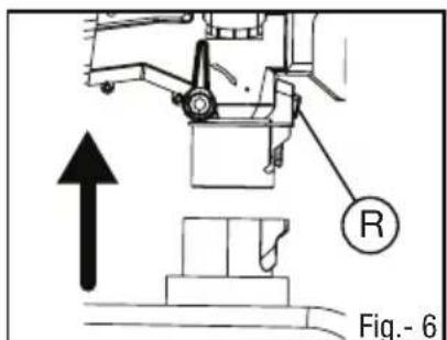
text_image
R Fig.- 6natural_image
Diagram showing a vehicle's wheel assembly before and after assembly, labeled Fig.-7 (no text or symbols on the diagram itself)natural_image
Technical line drawing of a mechanical device with an arrow indicating assembly or operation (no text or symbols present)natural_image
Diagram of a robotic arm with rotating wheel and textured grip, labeled Fig.-12 (no text or symbols on diagram itself)text_image
Technical diagram of a mechanical assembly with numbered components labeled 5 and 8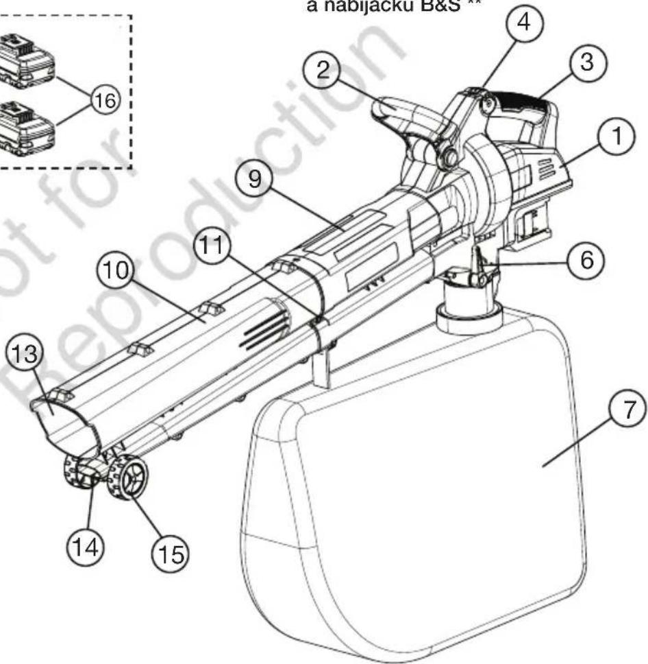
text_image
a Habijacku B&S 1 2 3 4 16 9 11 10 6 7 13 14 15
natural_image
Technical line drawing of a mechanical component with directional arrow and label 'Obr. 2' (no readable text or symbols)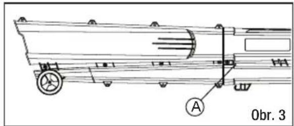
text_image
Obr. 3 A
natural_image
Technical line drawing of a mechanical assembly with no visible text or symbols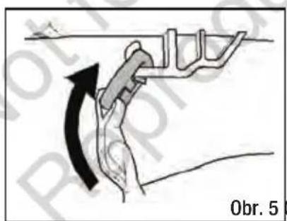
text_image
Obr. 5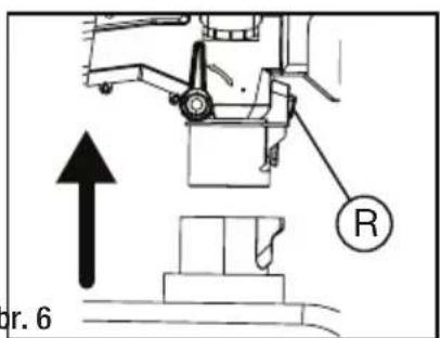
text_image
or. 6natural_image
Diagram showing a vehicle wheel assembly before and after transformation, labeled 'Obr. 7' (no text or symbols on diagram itself)Montáž batérie
INŠTALÁCIA BATÉRIÍ
natural_image
Technical line drawing of a mechanical device with two components and an arrow indicating direction (no text or symbols)VYBERANIE BATÉRIÍ
text_image
Obr. 10 ASpustenie a zastavenie
text_image
Obr. 11 S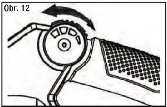
text_image
Obr. 12text_image
Technical diagram of a mechanical assembly with numbered components labeled 5 and 8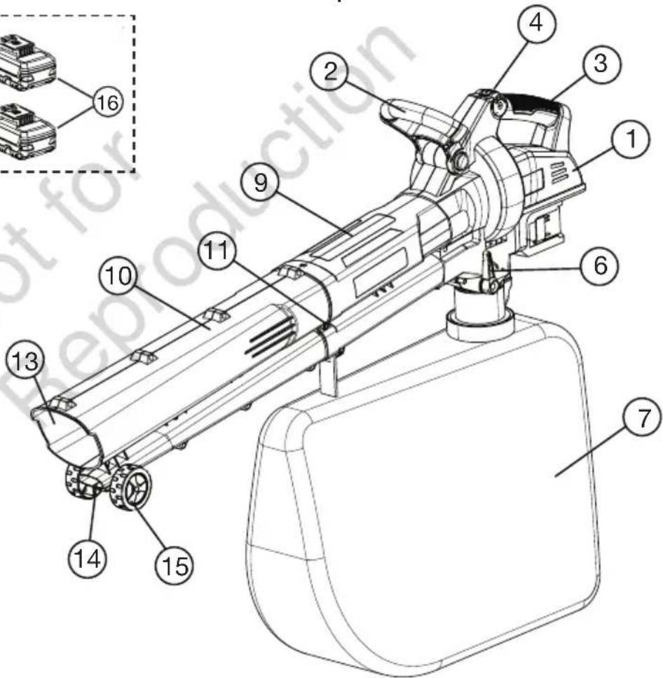
text_image
Technical diagram of a mechanical device with numbered components, including a zoomed-in inset view.
natural_image
Technical line drawing of a mechanical cart or trailer with directional arrow and label 'Sl.- 2' (no readable text or symbols)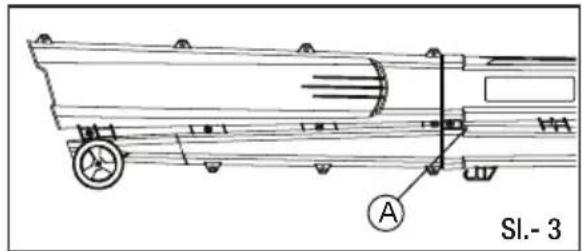
text_image
Sl.- 3 A
natural_image
Technical line drawing of a mechanical assembly with no visible text or symbols
text_image
SI.- 5 $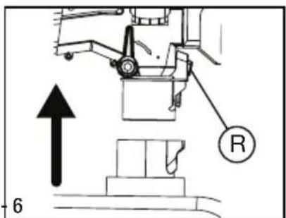
text_image
Technical diagram showing mechanical assembly with labeled component 'R' and an upward arrow, likely from an engineering or manufacturing context.natural_image
Technical line drawing of a mechanical assembly with an arrow indicating direction (no text or symbols)ODSTRANJEVANJE BATERIJ
natural_image
Diagram of a mechanical device with rotating components and directional arrows (no text or symbols)text_image
Technical diagram of a mechanical assembly with numbered components labeled 5 and 8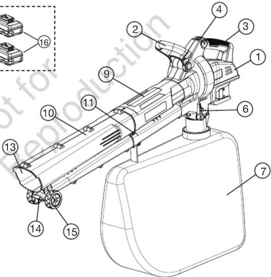
text_image
Technical diagram of a mechanical device with numbered components, including a zoomed-in inset showing internal parts.
natural_image
Technical line drawing of a mechanical cart or trailer with directional arrow indicating motion (no text or symbols)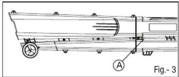
natural_image
Technical line drawing of a mechanical vehicle with labeled component A, no readable text or symbols present
natural_image
Technical line drawing of a mechanical assembly with no visible text or symbols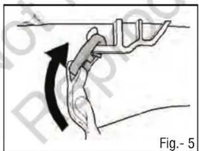
natural_image
Diagram of a hand gripping a mechanical component with an arrow indicating rotation (no text or symbols)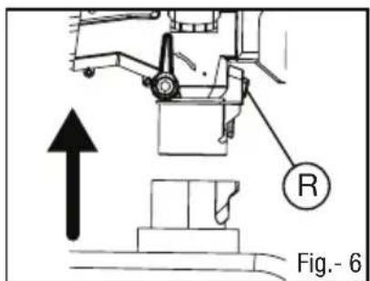
text_image
R Fig.- 6natural_image
Diagram showing a mechanical assembly before and after transformation, labeled Fig.-7 (no text or symbols on the diagram itself)PROCEDIMIENTOS DE MONTAJE
natural_image
Technical line drawing of a mechanical device with two components, one showing an arrow indicating assembly or operation (no text or symbols present)EXTRAER LAS BATERÍAS
natural_image
Diagram of a mechanical device with rotating components and directional arrows (no text or symbols)text_image
Technical diagram of a mechanical assembly with numbered components labeled 5 and 8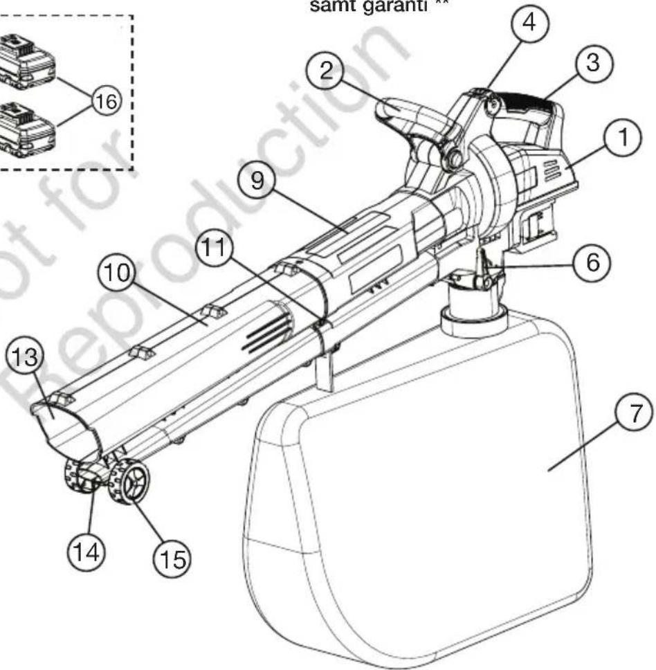
text_image
samt garanti 1 2 3 4 16 9 11 10 6 7 13 14 15
natural_image
Technical line drawing of a mechanical component with directional arrow and label 'Bild - 2' (no readable text or symbols)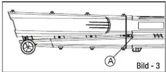
natural_image
Technical line drawing of a mechanical vehicle with labeled component A, no readable text or symbols beyond label
natural_image
Technical line drawing of a mechanical assembly with no visible text or symbols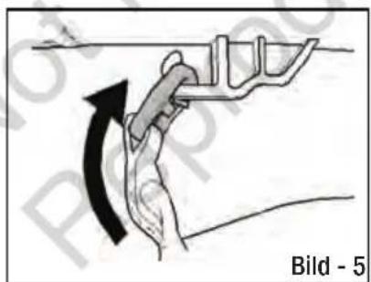
natural_image
Diagram of a hand gripping a mechanical component with an arrow indicating rotation (no text or symbols)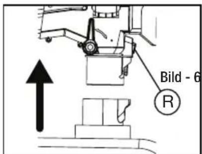
natural_image
Diagram showing a mechanical assembly before and after transformation, labeled 'Bild.-7' (no text or symbols on the diagram itself)MONTERINGS FÖRFARANDEN
Fästa batteriet
INSTALLERA BATTERI
natural_image
Technical line drawing of a mechanical assembly with two components and an arrow indicating direction (no text or symbols)TA BORT BATTERIERNA
natural_image
Diagram of a mechanical device with rotating components and directional arrows, no readable text or symbols©2020 Briggs & Stratton Corporation. All rights reserved.
No part of this booklet may be reproduced by any means without prior written permission.
All information herein is subject to change without notice.
Murray is a registered trademark of Briggs & Stratton Corporation.
WWW.MURRAY.COM