RST-280 - Welding machine Toolcraft - Free user manual and instructions
Find the device manual for free RST-280 Toolcraft in PDF.

User questions about RST-280 Toolcraft
0 question about this device. Answer the ones you know or ask your own.
Ask a new question about this device
Download the instructions for your Welding machine in PDF format for free! Find your manual RST-280 - Toolcraft and take your electronic device back in hand. On this page are published all the documents necessary for the use of your device. RST-280 by Toolcraft.
USER MANUAL RST-280 Toolcraft
GB Operating Instructions
RST-280 Rework Station
Item no: 2617831
F Mode d'emploi
text_image
A B REAL SET REAL SET J I 888°E 888°E H G 8888° 8888 F E C Dnatural_image
Technical line drawing of a soldering iron with a curved tip and threaded shaft (no text or symbols)1 Operating Instructions for download.... 24
2 Intended use 24
3 Delivery contents 24
4 Description of symbols.... 24
5 Safety instructions 25
5.1 Read first! 25
5.2 Personal safety.... 25
5.3 General 25
5.4 Handling 25
5.5 Operating environment.... 25
5.6 Operation.... 26
5.7 Mains cable 26
5.8 Soldering iron 27
5.9 Hot air gun 27
5.10 Accessories 27
5.11 Replacement parts 27
6 Product overview 28
6.1 Main unit.... 28
6.2 Display.... 29
7 Setting up.... 29
7.1 Mounting the hot air gun holder.... 29
7.2 Setting up the soldering iron.... 30
8 Global settings 30
8.1 Making global settings.... 30
8.2 Available global settings.... 30
8.2.1 Button sound 30
8.2.2 Temperature unit.... 30
8.2.3 Password protection.... 30
9 Hot air station.... 31
9.1 Operation modes.... 31
9.2 Operating the hot air gun.... 31
9.3 Locking operational settings.... 32
9.4 Activating nozzle-cooling.... 32
9.5 Setting temperatures 32
9.6 Setting air volume.... 32
9.7 Setting operation timers 33
9.8 Calibrating temperature.... 33
9.9 Using default shortcuts.... 33
9.10 Assigning custom shortcuts.... 34
10 Soldering iron.... 34
10.1 Operation modes.... 34
10.2 Operating the soldering iron 34
10.3 Setting sleep timers.... 35
10.4 Calibrating temperature.... 35
10.5 Locking operational settings.... 35
10.6 Using default shortcuts.... 36
10.7 Assigning custom shortcuts.... 36
11 Factory settings 36
11.1 Restoring factory settings.... 36
11.2 Factory settings.... 37
11.3 Factory shortcuts - Hot air gun 37
11.4 Factory shortcuts - Soldering iron 37
12 Cleaning.... 37
12.1 Cleaning the main unit.... 37
12.2 Cleaning the hot air gun 37
12.3 Cleaning the soldering iron.... 38
13 Troubleshooting.... 38
13.1 Troubleshooting the hot air gun.... 38
13.2 Troubleshooting the soldering iron 38
14 Maintenance 38
14.1 Replacing the soldering iron tip 38
14.2 Replacing the fuse of the main unit 39
15 Disposal 39
16 Technical data 39
16.1 Main unit.... 39
16.2 Hot air gun.... 40
16.3 Soldering iron 40
16.4 Soldering iron holder 40
16.5 ESD cable 40
17 Spare parts 41
1 Operating Instructions for download

Use the link www.conrad.com/downloads (alternatively scan the QR code) to download the complete operating instructions (or new/current versions if available). Follow the instructions on the web page.
2 Intended use
The product is a rework station. The product is intended to be used for de-soldering and soldering surface-mounted electronic components.
The product is intended for indoor use only. Do not use it outdoors.
Contact with moisture must be avoided under all circumstances.
If you use the product for purposes other than those described, the product may be damaged.
Improper use can result in short circuits, fires, electric shocks or other hazards.
The product complies with the statutory national and European requirements.
For safety and approval purposes, you must not rebuild and/or modify the product.
Read the operating instructions carefully and store them in a safe place. Make this product available to third parties only together with the operating instructions.
All company names and product names are trademarks of their respective owners. All rights reserved.
3 Delivery contents
Main unit
Soldering Iron
Soldering iron stand
Ground wire
Hot air gun holder
4x hot air nozzles
Mains cable
Operating instructions
4 Description of symbols
The following symbols are on the product/appliance or are used in the text:

The symbol warns of hazards that can lead to personal injury.

The symbol warns of dangerous voltage that can lead to personal injury by electric shock.
5 Safety instructions

Read the operating instructions carefully and especially observe the safety information. If you do not follow the safety instructions and information on proper handling, we assume no liability for any resulting personal injury or damage to property. Such cases will invalidate the warranty/guarantee.
5.1 Read first!
This appliance can be used by children aged from 8 years and above and persons with reduced physical, sensory or mental capabilities or lack of experience and knowledge if they have been given supervision or instruction concerning use of the appliance in a safe way and understand the hazards involved.
■ Children shall not play with the appliance.
- Cleaning and user maintenance shall not be made by children without supervision.
5.2 Personal safety
■ Never work under the influence of alcohol or medication.
Splashing solder might cause serious burns or eye damage. Wear suitable protective clothing and safety goggles when soldering/de-soldering.
- Do not ingest solder. Do not eat or drink during soldering.
■ Wash your hands thoroughly after working with solder.
■ Ensure that there is sufficient ventilation while soldering. Vapours can be harmful to your health.
5.3 General
The product is not a toy. Keep it out of the reach of children and pets.
Do not leave packaging material lying around carelessly. This may become dangerous playing material for children.
If you have questions which remain unanswered by this information product, contact our technical support service or other technical personnel.
- Maintenance, modifications and repairs must only be completed by a technician or an authorised repair centre.
5.4 Handling
- Handle the product carefully. Jolts, impacts or a fall even from a low height can damage the product.
5.5 Operating environment
Place the product on a clean, level, non-flammable surface of a sufficient size.
■ Protect the product against vibrations.
- Keep flammable or combustible materials (example: curtains) away to prevent fire.
■ Always operate the product on a non-flammable and heatproof surface.
Do not place the product on valuable furniture without using suitable protection, as this may result in scratch marks, pressure points, discolouration or burn marks.
■ Ensure that there is sufficient lighting.
- Keep your work area clean and tidy.
- Do not place the product under any mechanical stress.
- Protect the appliance from extreme temperatures, strong jolts, flammable gases, steam and solvents.
- Protect the product from high humidity and moisture.
■ Protect the product from direct sunlight.
5.6 Operation
- Consult an expert when in doubt about the operation, safety or connection of the product.
If it is no longer possible to operate the product safely, take it out of operation and protect it from any accidental use. DO NOT attempt to repair the product yourself. Safe operation can no longer be guaranteed if the product:
– is visibly damaged,
– is no longer working properly,
– has been stored for extended periods in poor ambient conditions or
– has been subjected to any serious transport-related stresses.
5.7 Mains cable

Do not modify or repair mains supply components including mains plugs, mains cables, and power supplies. Do not use damaged components. Risk of death by electric shock!
The mains outlet must be located near to the device and be easily accessible.
- Never plug in or unplug the mains plug when your hands are wet.
- Never pull the mains plug from the socket by pulling at the cable. Always pull it from the mains socket using the intended grips.
■ Unplug the mains plug from the mains socket if you do not use the device for an extended period of time.
- Disconnect the mains plug from the mains socket in thunderstorms for reasons of safety.
■ Make sure that the mains cable is not squeezed, bent, damaged by sharp edges or put under mechanical stress.
- Avoid excessive thermal stress on the mains cable from extreme heat or cold.
Do not modify the mains cable. Otherwise the mains cable may be damaged. A damaged mains cable can cause a deadly electric shock.
- Do not touch the mains cable if it is damaged.
- First, power down the respective mains socket (e.g. via the respective circuit breaker) and then carefully pull the mains plug from the mains socket.
- Never use the product if the mains cable is damaged.
A damaged mains cable may only be replaced by the manufacturer, a workshop commissioned by the manufacturer or a similarly qualified person, so as to prevent any danger.
- Ensure that cables are not pinched, kinked or damaged by sharp edges.
■ Always lay cables so that nobody can trip over or become entangled in them. This poses a risk of injury.
5.8 Soldering iron
■ Always place the soldering iron in the stand/holder if you do not use it.
- Do not leave the soldering iron unattended if switched on.
- Do not touch the hot soldering iron tip to prevent burns.
■ Always keep the soldering tip away from the power cord.
- Switch the soldering iron off if you do not use it for extended periods.
5.9 Hot air gun
Heat can ignite combustible materials and result in fire.
- Keep away combustible materials such as flammable gases, vapours, or dust.
– Remember that heat can be conducted to combustible materials which are out of sight.
- Do not leave the hot air gun unattended if switched on.
Do not point the flow of hot air at people or animals as this may cause burn injuries!
- Do not touch the hot air heat gun to prevent burns.
- Do not attempt to remove a tip from the airgun when it is hot to prevent burns.
■ Always place the hot air gun on the provided holder if you do not use it.
■ Make sure that there is enough space in the direction from which the hot air nozzle discharges hot air. The hot air may cause a fire if there is not enough space!
■ Never use the workstation to heat up liquids or gases.
- Never point the flow of hot air at the main unit, mains cable, hose or other parts.
5.10 Accessories
- Accessories and components that are not compatible with the product can damage the product or result in hazards. Only use the supplied components and accessories.
5.11 Replacement parts
■ Only use replacement parts designed for the product to prevent hazards.
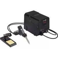
6 Product overview
6.1 Main unit
text_image
1 2 3 4 5 6 7 89101113 12 14 15 16| Component Description/Function | ||
| 1 Main unit | ||
| 2 Display | ||
| 3 | Menu selector buttonsTEMPfor soldering iron | Navigate menus, adjust settings and make selections. |
| 4 Soldering | iron power button Switch the soldering iron on and off. | |
| 5 Soldering | iron | |
| 6 Soldering | iron stand | |
| 7 Copper wool holder | ||
| 8 Power switch for main unit Switch on and off the main unit. | ||
| 9 | Settings buttons (1/2/3) for soldering iron | Adjust soldering iron settings via the menu.Activate shortcuts. |
| 10 Soldering | iron connection port Connect the soldering iron. | |
| 11 | Settings buttons (1/2/3) for hot air gun | Adjust hot air gun settings via the menu.Activate hot air gun shortcuts. |
| 12 ESD wire | connection port At the rear: | Connect the included ESD wire. |
| 13 Hot air gun Lift the hot air gun from the holder to activate it. | ||
| 14 Air volume selection dial Set the air volume of the hot air gun. | ||
| 15 | Menu selector buttons TEMP for hot air gun | Navigate menus and make selections. |
| 16 Hot air gun holder | ||
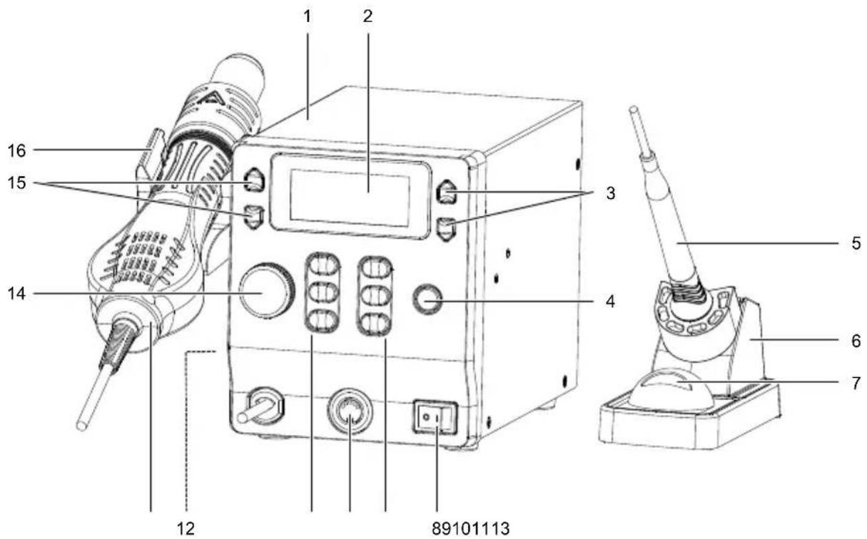
6.2 Display
text_image
A B REAL SET REAL SET J 888°E 888°E C I 888°E D H 888°E D G 8888° 8888 F ELeft side: Hot air gun
Right side: Soldering iron
| Indication Description/Function | ||
| A Indicator | REAL Indicator shows if the settings menu is deactivated. | |
| B Indicator | SET Indicator shows if the settings menu is activated. | |
| C Temperature unit | ||
| D Actual soldering tip temperature | ||
| E Preset temperature | ||
| F Target air volume | ||
| G Fan indicator Indicator shows if the fan runs. | ||
| H Settings lock indicator Indicator shows if the operation settings are locked. | ||
| I Actual hot air temperature | ||
| J | Bar indicator of heating power | More bars indicate a higher temperature. |
7 Setting up
7.1 Mounting the hot air gun holder
- Screw the hot air gun holder to the left side of the main unit using the supplied screws.
7.2 Setting up the soldering iron
Important:
- Only connect the supplied soldering iron or a replacement soldering iron of identical type.
-
You cannot adjust soldering iron settings if the soldering iron is disconnected. If the soldering iron is disconnected and the main unit switched on, the display shows S-E.
-
Connect the soldering iron to the soldering iron connection port.
- Place the soldering iron into the soldering iron stand.
8 Global settings
Global settings apply to the hot air gun and the soldering iron.
8.1 Making global settings
You can perform global settings either via the hot air gun menu or the soldering iron menu.
- Press and hold the settings buttons 1 and 3 at the same time until the display shows SET.
- Navigate to the menu entry using the settings buttons 1 and 3.
- Use the menu selector buttons TEMP to adjust the value.
- Save the entry by pressing the settings button 2.
8.2 Available global settings
8.2.1 Button sound
| Menu entry Value Description | ||
| /bL ON Sound on | ||
| /bL OFF Sound off |
8.2.2 Temperature unit
| Menu entry Value Description | ||
| /C-F - °F Degrees Fahrenheit | ||
| /C-F - °C Degrees Celsius |
8.2.3 Password protection
Password protection protects user settings against modification and is useful if the product is used by multiple users. The master password can unlock the menu in any case.
| Menu entry Value Description | ||
| /Psd --- No password protection | ||
| /Psd 906 Master password: | The master password can unlock the menu. Use the master password if you forgot your password. | |
| /Psd 001...905 Allocate users | 907...999 |
Note:
After you set a password, you cannot disable it by setting the menu entry /Psd to OFF. Remove password protection by restoring the factory settings. Refer to Restoring factory settings [▶ 36] for instructions.
9 Hot air station
9.1 Operation modes
Working mode
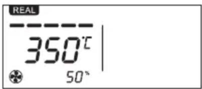
text_image
REAL 350°C 50°In working mode, the hot air gun is fully operational.
Standby mode
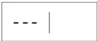
text_image
- - - |In standby mode, the hot air gun does not heat or blow air.
Place the hot air gun on the hot air gun holder to activate the standby mode.
Remove the hot air gun from the hot air gun holder to re-activate the hot air gun.
9.2 Operating the hot air gun
Preconditions:
√ You have installed the hot air gun holder.
- Place the hold air gun onto the hot air gun holder.
- Switch the main unit on by flipping the power switch I/O to the position I.
- Wait for the main unit to start up.
- Switch the hot air gun on by lifting it from the hot air gun holder.
→ The hot air gun heats up.
→ The display shows the actual temperature and REAL (actual temperature).
- Switch the hot air gun off by placing it onto the hot air gun holder.
→ The hot air gun activates the cooling mode to cool down the nozzle.
→ If the nozzle is cooled down, then the hot air gun stops.
- After use, switch the main unit off by flipping the power switch I/O to the position O.
9.3 Locking operational settings
Lock all settings to prevent accidental modifications to settings. The lock is maintained even after the main unit is switched off.
| Menu entry Value Description | ||
| /Loc ON The settings are locked. | The display shows the lock symbol.The settings cannot be modified. | |
| /Loc OFF The settings are unlocked. | The settings can be modified. | |
- Press and hold the settings buttons 1 and 3 at the same time until the display shows SET.
- Navigate to the menu entry using the settings buttons 1 and 3.
- Use the menu selector buttons TEMP to adjust the value.
- Save the entry by pressing the settings button 2.
Note:
The locking function does not prevent users from entering the menu and making changes.
9.4 Activating nozzle-cooling
The nozzle-cooling function allows you to quickly cool the nozzle of the hot air gun.
Preconditions:
√ The hot air gun is operating.
- Press the settings button 1 to activate nozzle-cooling.
→ The display shows C-L to indicate nozzle-cooling.
Important:
If you assign your own shortcut to the settings button 1, then the nozzle cooling function does not function as described.
9.5 Setting temperatures
You can adjust the hot air gun temperature while the hot air gun is off or operating.
- Use the selector buttons TEMP to set a temperature value. Press and hold the buttons to fast-adjust the temperature value.
→ If you release the selector button, the temperature value is stored.
9.6 Setting air volume
- Rotate the air volume dial to adjust the air volume.
→ The display shows the air volume output as a percentage value.
9.7 Setting operation timers
Set a timer to control for how long the hot air gun heats and maintains the set temperature. After the timer elapses, the hot air gun switches to cooling mode.
| Menu entry Value Description | |||
| /Ht OFF Timer is off | |||
| /Ht 10...900 Timer duration in seconds | |||
- Press and hold the settings buttons 1 and 3 at the same time until the display shows SET.
- Navigate to the menu entry using the settings buttons 1 and 3.
- Use the menu selector buttons TEMP to adjust the value.
- Save the entry by pressing the settings button 2.
9.8 Calibrating temperature
If you have determined that the actual temperature that exits the nozzle deviates from the displayed temperature (tD), calibrate the temperature using a temperature offset ( t ).
After you set the offset, the displayed temperature is tNew= tD + Δt.
| Menu entry Value Description | |||
| /CAL | -50...-01°C | -90...-01°F | Negative temperature offset |
| /CAL | -00°C | -00°F | Without temperature offset |
| /CAL | 01...50°C | 01...90°F | Positive temperature offset |
- Press and hold the settings buttons 1 and 3 at the same time until the display shows SET.
- Navigate to the menu entry using the settings buttons 1 and 3.
- Use the menu selector buttons TEMP to adjust the value.
- Save the entry by pressing the settings button 2.
9.9 Using default shortcuts
If the hor air gun is in operation, the settings buttons act as shortcuts. The hot air gun is programmed with three default shortcuts.
| Shortcut button Temperature Airflow | ||
| 1 Cool 50 % | ||
| 2 300 °C 50 % | ||
| 3 400 °C 50 % |
You can use shortcuts in two ways:
- Press a shortcut button and then lift the hot air gun from the hot air gun holder.
- Lift the hot air gun from the hot air gun holder and then press a shortcut button.
9.10 Assigning custom shortcuts
By assigning custom shortcuts to the settings buttons, you can quickly switch to presets during operation. You can assign shortcuts to any of the settings buttons.
- Adjust the temperature and the air volume.
- Save the shortcut by pressing and holding a settings button (1/2/3) until the values on the display flash once.
- Use the shortcut by pressing the settings button to which the shortcut is assigned.
10 Soldering iron
10.1 Operation modes
Working mode
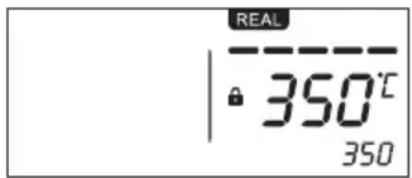
text_image
REAL 350°C 350In working mode, the soldering iron is fully operational.
Standby mode
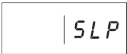
text_image
| SLPIn standby mode, the soldering iron maintains a temperature of 200 °C .
Reactivate the working mode by pressing any of the settings buttons of the soldering iron.
10.2 Operating the soldering iron
- Place the soldering iron into the soldering iron stand.
- Switch the main unit on by flipping the power switch I/O to the position I.
- Wait for the main unit to start up.
→ The display shows OFF. -
Switch the soldering iron on by pressing the soldering iron power button SOLDERING IRON ON/OFF.
→ The soldering iron heats up.
→ The display shows the actual temperature. -
Wait for the temperature value to stabilize on the display.
- The soldering iron is ready for use.
- After use, switch the soldering iron off by pressing the soldering iron power button SOLDERING IRON ON/OFF.
- After use, switch the main unit off by flipping the power switch I/O to the position O.
10.3 Setting sleep timers
Set a sleep timer to automatically lower the soldering iron tip temperature after a preset amount of time.
For sleep timers to work, the soldering iron must be in the soldering iron stand. If you pick the soldering iron up again, the soldering iron tip heats up again to the preset temperature.
Sleep temperature
200 °C
Activating and deactivating
| Menu entry Value Description | ||
| /SLP OFF Sleep timer is deactivated | ||
| /SLP 01...60 Set a timer in minutes. |
- Press and hold the settings buttons 1 and 3 at the same time until the display shows SET.
- Navigate to the menu entry using the settings buttons 1 and 3.
- Use the menu selector buttons TEMP to adjust the value.
- Save the entry by pressing the settings button 2.
→ If a timer is set and the sleep time has elapsed, the display shows SLP and the soldering iron tip temperature is lowered.
10.4 Calibrating temperature
Calibrate a temperature using temperature offsets ( t ) if you have determined that the actual soldering iron temperature deviates from the displayed temperature ( t_D ).
After you set the offset, the displayed temperature is tNew= tD + Δt.
| Menu entry Value Description | |||
| /CAL | -50...-01°C | -90...-01°F | Negative temperature offset |
| /CAL | -00°C | -00°F | Without temperature offset |
| /CAL | 01...50°C | 01...90°F | Positive temperature offset |
- Press and hold the settings buttons 1 and 3 at the same time until the display shows SET.
- Navigate to the menu entry using the settings buttons 1 and 3.
- Use the menu selector buttons TEMP to adjust the value.
- Save the entry by pressing the settings button 2.
10.5 Locking operational settings
Lock all settings to prevent accidental modifications to settings. The lock is maintained even after the main unit is switched off.
| Menu entry Value Description | ||
| /Loc ON The settings are locked. | The display shows the lock symbol.The settings cannot be modified. | |
| /Loc OFF The settings are unlocked. | The settings can be modified. | |
- Press and hold the settings buttons 1 and 3 at the same time until the display shows SET.
- Navigate to the menu entry using the settings buttons 1 and 3.
- Use the menu selector buttons TEMP to adjust the value.
- Save the entry by pressing the settings button 2.
Note:
The locking function does not prevent users from entering the menu and making changes.
10.6 Using default shortcuts
If the soldering iron is in operation, the settings buttons act as shortcuts. The soldering iron is programmed with three default shortcuts.
| Shortcut button Temperature | ||
| 1 200 °C | ||
| 2 300 °C | ||
| 3 400 °C |
- Press a shortcut button to switch to the temperature value.
10.7 Assigning custom shortcuts
By assigning custom shortcuts to the settings buttons, you can quickly switch to presets during operation. You can assign shortcuts to any of the settings buttons.
- Adjust the soldering iron temperature.
- Save the shortcut by pressing and holding a settings button (1/2/3) until the values on the display flash once.
- Use the shortcut by pressing the settings button to which the shortcut is assigned.
11 Factory settings
11.1 Restoring factory settings
| Menu entry Value Description | ||
| /FAC | OFF | If FAC is set to OFF, the settings cannot be restored.This is a safety feature that prevents accidental restoring. |
| /FAC | ON | If FAC is set to ON, the settings can be restored. |
-
Press and hold the settings buttons 1 and 3 at the same time until the display shows SET.
-
Navigate to the menu entry using the settings buttons 1 and 3.
- Use the menu selector buttons TEMP to adjust the value.
- Restore the main unit to the factory settings by pressing the settings button2.
11.2 Factory settings
| Setting Default setting | |
| Timer OFF | |
| Operational settings lock OFF | |
| Temperature calibration 00 | |
| Temperature unit °C | |
| Password protection OFF | |
| Button sound ON |
11.3 Factory shortcuts - Hot air gun
| Shortcut button Temperature Airflow | ||
| 1 Cool 50 % | ||
| 2 300 °C 50 % | ||
| 3 400 °C 50 % |
11.4 Factory shortcuts - Soldering iron
| Shortcut button Temperature | ||
| 1 200 °C | ||
| 2 300 °C | ||
| 3 400 °C |
12 Cleaning
Important:
- Do not use aggressive cleaning agents, rubbing alcohol or other chemical solutions. They damage the housing and can cause the product to malfunction.
- Do not immerse the product in water.
12.1 Cleaning the main unit
- Disconnect the product from the power supply.
- Let the product cool down to ambient temperature.
- Clean the product with a dry, fibre-free cloth.
12.2 Cleaning the hot air gun
-
Disconnect the product from the power supply.
-
Let the product cool down to ambient temperature.
- Clean the product with a dry, fibre-free cloth.
12.3 Cleaning the soldering iron
- Disconnect the product from the power supply.
- Let the product cool down to ambient temperature.
- Clean the product with a dry, fibre-free cloth.
- Remove oxide from the soldering iron tip with a fine abrasive paper.
- Wipe the soldering iron tip clean with a dry cloth.
- Heat the soldering iron up and tin the soldering iron tip to prevent oxidation.
13 Troubleshooting
13.1 Troubleshooting the hot air gun
| Problem Possible cause Suggested solution | |
| Display shows S-E Sensor fault Contact technical support. | |
| Display shows H-E Heater fault Contact technical support. |
13.2 Troubleshooting the soldering iron
| Problem Possible cause Suggested solution | ||
| Display shows S-E | Soldering iron is disconnected Connect the soldering iron to the soldering iron connection port. | |
| Display shows S-E | Sensor fault Contact technical support. | |
| Display shows H-E | Heater fault Contact technical support. | |
14 Maintenance
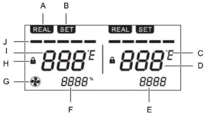
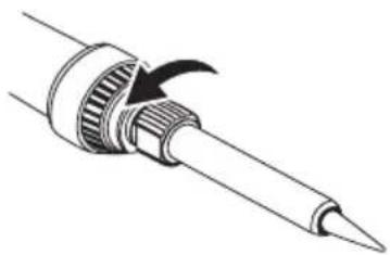
14.1 Replacing the soldering iron tip
Replace the soldering iron tip if it shows signs of significant wear and tear or if it no longer performs effectively.
- Switch the main unit off by flipping the power switch I/O into the position O.
- Disconnect the mains cable from the product.
- Let the soldering iron cool down to room temperature.
- Disconnect the soldering iron from the main unit.
- Remove the soldering tip by unscrewing it. See figure.
- Replace the soldering tip with a new one. Refer to Spare parts [▶ 41] for more information.
natural_image
Line drawing of a soldering iron with a curved tip and mechanical component (no text or symbols)14.2 Replacing the fuse of the main unit
The fuse is integrated into the power connector at the rear of the product.
- Switch the main unit off by flipping the power switch I/O into the position O.
- Allow the hot air gun and soldering iron to cool down completely.
- Disconnect the mains cable from the product.
- Unlock the fuse compartment with a flat-headed screwdriver and pull out the fuse tray.
- Replace the fuse with an equivalent one. Refer to "Technical data" for fuse data.
Tip:
Store a spare fuse in the spare fuse holder that is integrated into the fuse tray.
15 Disposal

This symbol must appear on any electrical and electronic equipment placed on the EU market. This symbol indicates that this device should not be disposed of as unsorted municipal waste at the end of its service life.
Owners of WEEE (Waste from Electrical and Electronic Equipment) shall dispose of it separately from unsorted municipal waste. Spent batteries and accumulators, which are not enclosed by the WEEE, as well as lamps that can be removed from the WEEE in a non-destructive manner, must be removed by end users from the WEEE in a non-destructive manner before it is handed over to a collection point.
Distributors of electrical and electronic equipment are legally obliged to provide free take-back of waste. Conrad provides the following return options free of charge (more details on our website):
in our Conrad offices
■ at the Conrad collection points
at the collection points of public waste management authorities or the collection points set up by manufacturers or distributors within the meaning of the ElektroG
End users are responsible for deleting personal data from the WEEE to be disposed of.
It should be noted that different obligations about the return or recycling of WEEE may apply in countries outside of Germany.
16 Technical data
16.1 Main unit
Input voltage.... 220 - 240 V/AC, 50 - 60 Hz
Power consumption.... 865 W
Fuse....T5A L250V
ESD safe .... Yes
Operating conditions.... 0 to +40 °C, <85 % RH
Storage conditions....-20 to +80 °C, <85 % RH
Cable length 1380 mm (±20 mm)
Dimensions (W x H x D) 125 x 149 x 200 mm
Weight 3.3 kg (with all accessories)
16.2 Hot air gun
Temperature range.... +100 to +500 °C
Heating time 46 s for 400 °C
Temperature accuracy.... ±35 °C
Temperature stability.... ±5 °C
Air pump type .... Brushless vortex fan
Maximum airflow.... 120 L/min
Cable length .... approx. 900 mm
Dimensions (∅ x H) 25.2 x 223 mm
Weight .... approx. 232 g
16.3 Soldering iron
Input voltage.... 220 - 240 V/AC
Power consumption.... 65 W
Temperature range.... +80 to +480 °C
Temperature stability.... ±2 °C
Heating time 48 s for 400 °C
Temperature accuracy.... ±10 °C
Cable length .... approx. 1100 mm
Dimensions (∅ x L).... 20 x 225 mm
Weight approx. 83 g
16.4 Soldering iron holder
Dimensions (W x H x D) 71 x 82 x 158 mm
Weight approx. 319 g
16.5 ESD cable
Cable length .... approx. 1800 m
17 Spare parts
Go to the product page on www.conrad.com for available spare parts and accessories.
F Sommaire
text_image
A B REAL SET REAL SET J 888°E 888°E C I H G 8888* 8888 D F Enatural_image
Diagram of a soldering iron with a curved tip and mechanical shaft (no text or symbols)text_image
A B REAL SET REAL SET J I 888°E 888°E C H 888°E D G 8888* 8888 F Enatural_image
Diagram of a soldering iron with a curved tip and mechanical shaft (no text or symbols)Copyright by Conrad Electronic SE *2617831_V1_0424_jh_mh_de 18014399715960843-1 I3/O1 en
GB
This is a publication by Conrad Electronic SE, Klaus-Conrad-Str. 1, D-92240 Hirschau (www.conrad.com).
All rights including translation reserved. Reproduction by any method (e.g. photocopying, microfilming or the capture in electronic data processing systems) requires prior written approval from the editor. Reprinting, also in part, is prohibited. This publication reflects the technical status at the time of printing.
Copyright by Conrad Electronic SE *2617831_V1_0424_jh_mh_en 18014399715960843-2 I3/O1 en