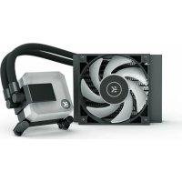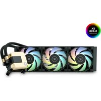
Elite Aurum 360 D-RGB - Computer cooling system EK Water Blocks - Free user manual and instructions
Find the device manual for free Elite Aurum 360 D-RGB EK Water Blocks in PDF.


User questions about Elite Aurum 360 D-RGB EK Water Blocks
0 question about this device. Answer the ones you know or ask your own.
Ask a new question about this device
Download the instructions for your Computer cooling system in PDF format for free! Find your manual Elite Aurum 360 D-RGB - EK Water Blocks and take your electronic device back in hand. On this page are published all the documents necessary for the use of your device. Elite Aurum 360 D-RGB by EK Water Blocks.
USER MANUAL Elite Aurum 360 D-RGB EK Water Blocks
EK-AIO Elite Aurum 360 D-RGB

natural_image
Abstract logo design with a white stylized 'K' inside a circle on a olive-brown background (no text or symbols)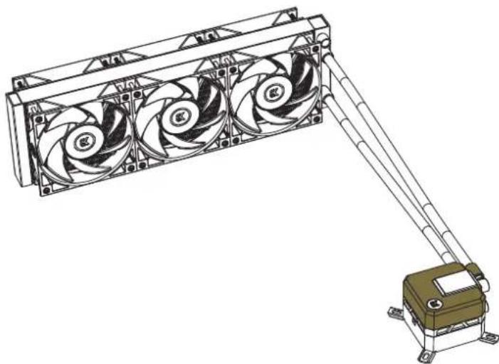
natural_image
Technical line drawing of a three-blade fan assembly mounted on a mechanical base (no text or symbols)To ensure safe and easy installation, please carefully read this manual before starting with the installation process!
Compatible with:
Intel Socket 115X / 1200 / 20XX CPUs
AMD Socket AM4 CPU

INFORMATION TO THE USER
This equipment has been tested and found to comply with the limits for a class B digital device, pursuant to part 15 of the FCC Rules. These limits are designed to provide reasonable protection against harmful interference in a residential installation. This equipment generates, uses and can radiate radio frequency energy and if not installed and used in accordance with the instructions, may cause harmful interference to radio communications. However, there is no guarantee that interference will not occur in a particular installation. If this equipment does cause harmful interference to radio or television reception, which can be determined by turning the equipment off and on, the user is encouraged to try to correct the interference by one or more of the following measures:
• Reorient or relocate the receiving antenna.
- Increase the separation between the equipment and receiver.
- Connect the equipment into an outlet on a circuit different from that to which the receiver is connected.
- Consult the dealer or an experienced radio/TV technician for help.
The user is cautioned that changes and modifications made to the equipment without the approval of manufacturer could void the user's authority to operate this equipment.
TABLE OF CONTENTS
- SAFETY PRECAUTIONS 4
- SPECIFICATIONS 4
- ENCLOSED IN THIS PACKAGE 5
MOUNTING KIT 5 - INSTALLATION - INTEL LGA-115X/1200 SOCKET 6
STEP 1: REMOVING THE MOTHERBOARD 6
STEP 2: ATTACHING THE BACKPLATE TO THE MOTHERBOARD 6
STEP 3: ATTACHING MOUNTING SCREWS 6
STEP 4: INSTALLING THE FANS TO THE RADIATOR 6
STEP 5: REMOVING THE COLD-PLATE PROTECTIVE COVER 6
STEP 6: MOUNTING BRACKETS INSTALLATION 6
STEP 7: PUMP UNIT INSTALLATION 6
STEP 8: INSTALLING THE ASSEMBLY OF FANS AND THE RADIATOR INTO A PC CASE 7
STEP 9: PUMP - CONNECTING CABLES 7
STEP 10: FANS - CONNECTING CABLES 8
OPTIONAL STEP! APPLYING THE THERMAL COMPOUND 9 - INSTALLATION - INTEL LGA-20XX SOCKET 9
STEP 1: ATTACHING MOUNTING SCREWS (LGA-20XX) 9 - INSTALLATION - AMD AM4 SOCKET 9
STEP 1: REMOVING THE ORIGINAL PLASTIC HOLD-DOWN CLAMPS (AMD) 9
STEP 2: ATTACHING MOUNTING SCREWS [AMD]
STEP 3: INSTALLING THE FANS TO THE RADIATOR (AMD) 9
STEP 4: REMOVING THE COLD-PLATE PROTECTIVE COVER (AMD) 9
STEP 5: MOUNTING BRACKETS INSTALLATION [AMD] 10
STEP 6: PUMP UNIT INSTALLATION [AMD] 10
STEP 7: INSTALLING THE ASSEMBLY OF FANS AND THE RADIATOR INTO A PC CASE (AMD) 10
STEP 8: PUMP - CONNECTING CABLES [AMD] 11
STEP 9: FANS - CONNECTING CABLES (AMDI) 11
OPTIONAL STEPI APPLYING THE THERMAL COMPOUND 12 - SUPPORT AND SERVICE 12
- SOCIAL MEDIA 12
This product is intended for installation by expert users only. Please, consult with a qualified technician. Improper installation may result in damage to your equal assumes no liability whatsoever, expressed or implied, for the use of these products or their installation. The following instructions are subject to change without notice. Please visit our web site at www.ekwo.com for updates.

NOTE ON ENVIRONMENTAL PROTECTION:
After the implementation of the European Directive 2012/19/EU in the national legal system, the following applies:
• Electrical and electronic devices may not be disposed of with domestic waste.
- Consumers are obliged by law to return electrical and electronic devices at the end of their service lives to the public collecting points set up for this purpose or point of sale. Details to this are defined by the national law of the respective country. This symbol on the product, the instruction manual or the package indicates that a product is subject to these regulations. By recycling, reusing the materials or other forms of utilising old devices, you are making an important contribution to protecting our environment.
1. SAFETY PRECAUTIONS
- Keep and store the product away from the reach of children.
- Check the component list and condition of the product before installation. If you encounter a problem, contact the shop where you have purchased the product to get a replacement or a refund.
- EKWB d.o.o. is not responsible for any damages due to external causes, including but not limited to: improper use, problems with electrical power, accident, neglect, alteration, repair, improper installation, and improper testing.
- CPU and motherboard are subject to damage if the product is incorrectly installed
- The excessive force exerted on the tan may cause damage to the tan and/or system.
- This product is a CPU liquid cooling solution kit, comprising of individual original EKWB parts. Combining this liquid cooling unit with parts, other than EK Water Block products, may lead to warranty loss.
- Product design and specifications may be revised to improve quality and performance.
-
You must not run the pump below 20% RPM. The pump must stay within a 20-100% PWM duty cycle at all times. We recommend to always run the pump at 100%.
-
SPECIFICATIONS pment. ER Water Blocks
| Model EK-AIO Elite Aurum 360 D-RGB | |
| Radiator Dimensions 397 x 120 x 27 mm | |
| Fan | Dimensions 120 x 120 x 25 mm (6x) |
| Speed 600-2200 RPM ±10% (PWM: 25-100%) | |
| Life Expectancy 50,000 hours | |
| Noise Level 33.5 d3 | |
| Bearing Type Fluid Dynamic bearing (FDB) | |
| Connector 4-Pin | |
| Rated Voltage 1.7V | |
| Pump | Dimensions (mm) BB x 70 x 63 mm |
| RPM 1000 - 3300 RPM + -10% (PWM Range: 25 - 100%) | |
| Life Expectancy 50,000 hours | |
| Input Current 0.65 =10% A | |
3. ENCLOSED IN THIS PACKAGE
EK-AIO Elite Aurum 360 D-RGB (1x)
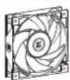
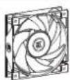
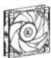
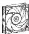
EK-Vardar S 120ER D-RGB (6x)
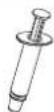
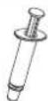
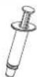
A tube of Thermal Paste (3830046998446 - EK-TIM Ectotherm (1g)) (1x)
Mounting Kit (1x)
User Manual (1x)
MOUNTING KIT
| Phillips Head Screw UNC 6-32 x 30mm(5 mm thread length)(12x / 8x) | Phillips Head ScrewUNC 6-32 x 6 mm(12x / 8x) | |
| Phillips Head Screw UNC 6-32 x 34mm(12x / 8x) |
| Thumb nut (Intel /AMD)(4x) | Mounting thumb screw for INTEL LGA 115x/ AMD AMI socket(4x) | ||
| Mounting thumb screw for Intel LGA 20XX socket(4x) | Spring(4x) | ||
| Mounting Plate Phillips Head M4 x 6 mm (for the installation of mounting brackets)(4x) | |||
| Intel LGA 115x Backplate(1x) | Intel mounting bracket(2x) | ||
| AMD mounting bracket(2x) | |||
| HUB (with PWM and D- RGB cable)(1x) |
4. INSTALLATION - INTEL LGA-115X/1200 SOCKET
STEP 1: REMOVING THE MOTHERBOARD
If your PC case doesn't have a cutout from the bottom CPU side of the motherboard, you will first need to remove the motherboard from your computer.
text_image
Intel LGA 115x BackplateSTEP 2: ATTACHING THE BACKPLATE TO THE MOTHERBOARD
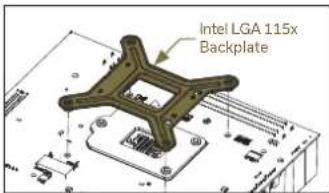
Install the Intel backplate for LGA-115x socket to the back of your motherboard. Align the holes on the motherboard with the holes on the backplate.
text_image
Mounting thumb screw for INTEL LGA 115x / AMD AM4 socketSTEP 3: ATTACHING MOUNTING SCREWS
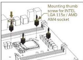
Install 4x LGA-115x mounting thumb screws through your motherboard to the backplate.
Thumb screws are to be installed without the use of tools (i.e. pliers).
Start fastening two thumb screws at a time, preferably in a cross pattern, but do not tighten them fully until all four are partially screwed in.
text_image
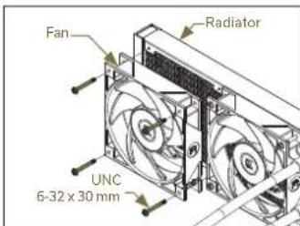
Fan Radiator UNC 6-32 x 30 mmSTEP 4: INSTALLING THE FANS TO THE RADIATOR
Attach the fans (3x) to the radiator using the UNC 6-32 x 30 mm screws.
text_image
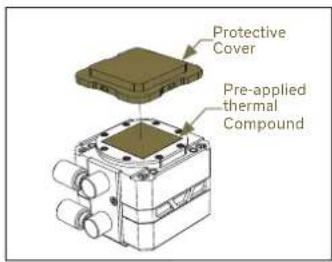
Protective Cover Pre-applied thermal CompoundSTEP 5: REMOVING THE COLD-PLATE PROTECTIVE COVER
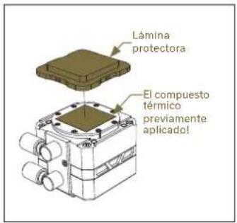
Remove the protective cover from the backside of the pump unit. It is there only to prevent the damage of the cold-plate and the pre-applied thermal compound that is on the cold-plate.
When removing the protective cover and proceeding with installation be careful not to touch or damage the pre-applied thermal compound!
text_image
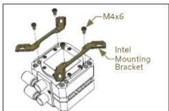
M4x6 Intel Mounting BracketSTEP 6: MOUNTING BRACKETS INSTALLATION
Use four M4x6 screws to install two Intel brackets onto the pump unit.
Be careful not to touch or damage the pre-applied thermal compound!
text_image
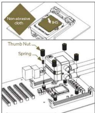
Non-abrasive cloth IHS Thumb Nut SpringSTEP 7: PUMP UNIT INSTALLATION
Wipe the CPU's contact surface (using a non-abrasive cloth pr a Q-tip as shown in the sample image).
Align the pump unit over the mounting screws and CPU as shown in the picture.
Place the enclosed compression springs and thumb nuts over the mounting screws (4x). Start fastening two thumb nuts at a time, preferably in cross pattern, and do not tighten them fully until all of them are partially screwed in.
text_image
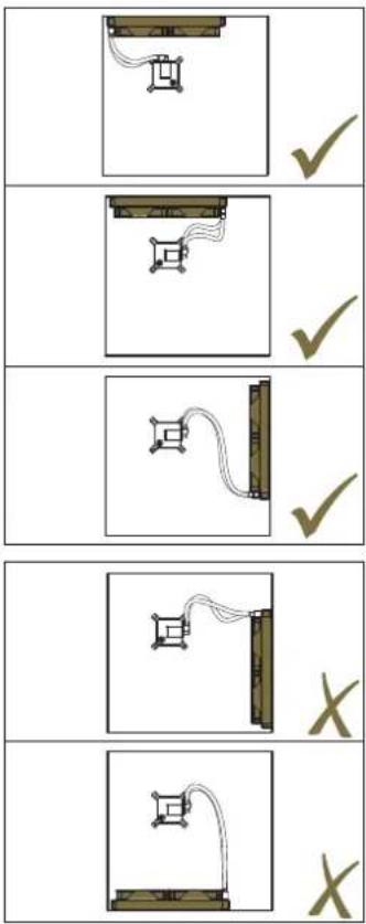
Diagram showing four sequential experimental setups with checkmarks and X marks indicating condition or measurement.STEP 8: INSTALLING THE ASSEMBLY OF FANS AND THE RADIATOR INTO A PC CASE
Radiator on top (recommended)
Vertical placement of the radiator with tubing at the bottom (recommended)
Vertical placement of the radiator with tubing at the top (not optimal)
Radiator at the bottom (should be avoided)
text_image
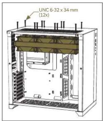
UNC 6-32 x 34 mm (12x)Option 1
Use the UNC 6-32 x 34 mm screws to attach the preassembled radiator-and-fans setup with the remaining three fans (to have six fans in total) to the PC chassis.
The orientation of the fans is crucial for achieving the best performance of the radiator.
Install the fans so that they will push the air through the radiator. To be sure about the fan orientation, you can look at the position of the EK logo on the side of the fan - it must be oriented the same way on both the upper and lower set of fans. It is also recommended that cables of all fans are facing the same direction for easier cable management.
Option 2
If there is not enough space inside your PC chassis to place all six fans on the radiator, you may position the remaining three somewhere else inside your PC.
In that case, use the UNC 6-32 x 6mm screws to attach the preassembled radiator and the fans to the PC chassis.
text_image
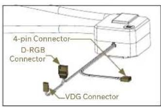
4-pin Connector D-RGB Connector VDG ConnectorSTEP 9: PUMP - CONNECTING CABLES
Step A:
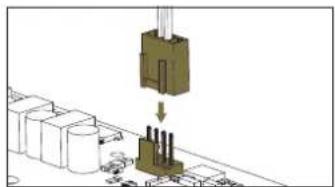
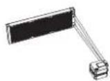
Plug the 4-pin PWM connector of the pump into the motherboard.
Do not use the same HUB that fans are connected to - the rotational speed (RPM) of the fan and the pump should be regulated separately.

natural_image
Diagram showing a mechanical assembly with a component being lifted by an arrow, no visible text or symbols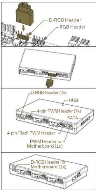
text_image
D-RGB Header RGB Header D-RGB Header (7x) HUB 4-pin PWM Header (7x) SATA 4-pin "Red" PWM Header PWM Header to Motherboard (1x) D-RGB Header to Motherboard (1x)Step B:
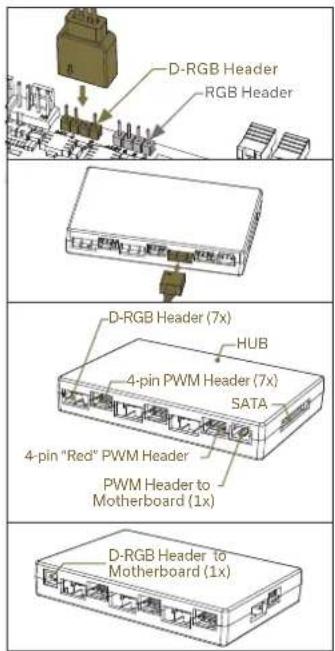
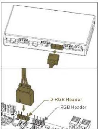
Plug the 3-pin connector of the pump's D-RGB LED light into the D-RGB HEADER on the motherboard or into one of the D-RGB (Addressable RGB) HEADERS on the HUB. The LEDs will work if the pin layout on the header is as follows: +5V, Data, Empty, Ground. With some motherboards, you can alternatively use a VDG connector instead of the D-RGB to connect the LEDs.

Please ensure that the arrow indicated on the connector is plugged into the 15V line as indicated on your motherb you put LED Diode to the 12V RGB HEADER you can damage the LEDs.

Connector is the same on D-RGB and RGB versions, but D-RGB version has 3 cables from connector to PCB; RGB version has 4 cables. If you connect D-RGB led to ordinary RGB header you can damage your motherboard or LED strip.
text_image
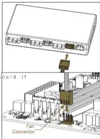
card. If Fan ConnectorStep A:
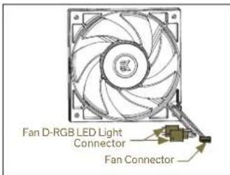
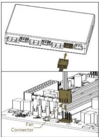
Plug all of the 4-pin PWM fan connectors into PWM headers on the HUB (6x). Make sure the red PWM header on the HUB is always used.
Plug the PWM connector from the HUB directly into the CPU fan header on the motherboard. Always use the CPU fan header if possible.
text_image
Fan D-RGB LED Light Connector Fan ConnectorSTEP 10: FANS - CONNECTING CABLES
text_image
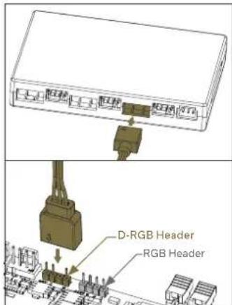
D-RGB Header RGB HeaderStep B:
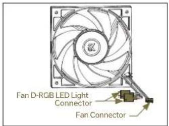
Plug the D-RGB connectors of the fans into the D-RGB HEADERS on the HUB (6x).
Plug the D-RGB connector from the HUB directly into the motherboard.
text_image
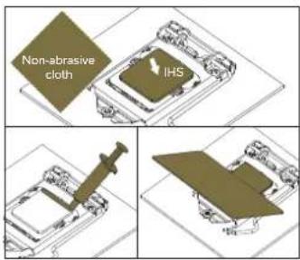
Non-abrasive cloth IHSOPTIONAL STEP! APPLYING THE THERMAL COMPOUND
This step is relevant only in the second installation of AIO o damaged the pre-applied paste on the backside of the pump unit! For the first installation, you don't need to apply the additional thermal compound to the CPU's contact surface!
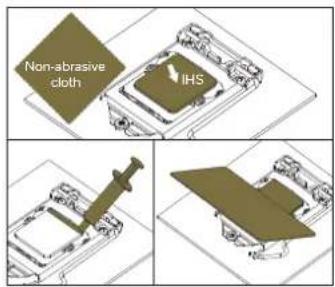
Wipe the CPU's contact surface (using a non-abrasive cloth or a Q-tip as shown in the sample image). On a clean IHS, apply a line of thermal compound and spread it over the whole CPU heat spreader (IHS) with a credit card or something similar.
text_image
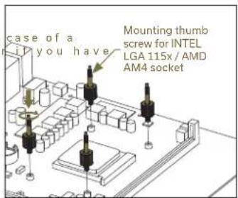
case of a you have Mounting thumb screw for INTEL LGA 115x / AMD AM4 socketSTEP 2: ATTACHING MOUNTING SCREWS (AMD)
Install 4x mounting thumb screw for AMD AM4 socket onto your motherboard. The screws are to be installed without the use of tools (i.e. pliers).
5. INSTALLATION - INTEL LGA-20XX SOCKET
text_image
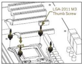
LGA-2011 M3 Thumb ScrewSTEP 1: ATTACHING MOUNTING SCREWS (LGA-20XX)
LGA-20xx (2066 / 2011 V3 / 2011) socket motherboards do not require backplate installation. Install 4x LGA-20XX mounting thumb screws into M4 threaded stubs on the integrated latch mechanism (ILM) of the LGA-20XX socket.
Thumb screws are to be installed without the use of tools (i.e. pliers).

Continue installation by following the instructions from Step 4 on page 6
text_image
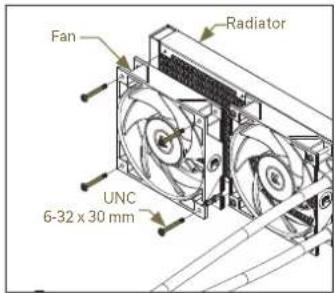
Fan Radiator UNC 6-32 x 30 mmSTEP 3: INSTALLING THE FANS TO THE RADIATOR (AMD)
Attach the fans (3x) to the radiator with the UNC 6-32 x 30mm screws.
6. INSTALLATION - AMD AM4 SOCKET
text_image
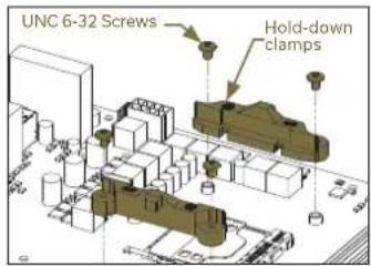
UNC 6-32 Screws Hold-down clampsSTEP 1: REMOVING THE ORIGINAL PLASTIC HOLD-DOWN CLAMPS (AMD)
Using Philips-head screwdriver, remove the 4 UNC 6-32 screws securing the original plastic hold-down clamps around the socket as shown in the image. Keep the original AMD® backplate and remove the hold-down clamps to store them away. See the image for further part identification.
text_image
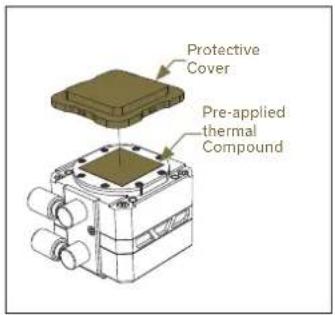
Protective Cover Pre-applied thermal CompoundSTEP 4: REMOVING THE COLD-PLATE PROTECTIVE COVER (AMD)
Remove the protective cover from the backside of the pump unit. It is there only to prevent the damage of the cold-plate and the pre-applied thermal compound that is on the cold-plate.
When removing the protective cover and proceeding with installation be careful not to touch or damage the pre-applied thermal compound!
text_image
M4x6 AMD Mounting Bracket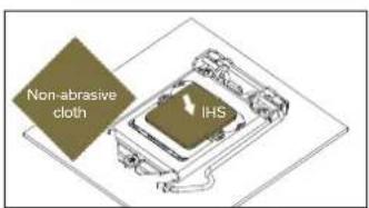
text_image
Non-abrasive cloth IHS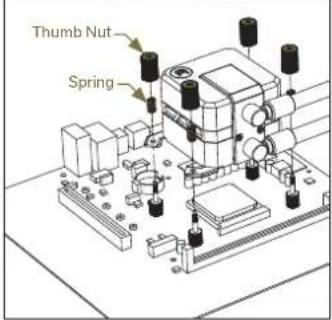
text_image
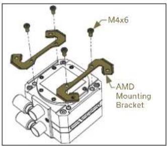
Thumb Nut SpringSTEP 5: MOUNTING BRACKETS INSTALLATION (AMD)
Use four M4x6 screws to install two AMD brackets onto the pump unit.
Be careful not to touch or damage the pre-applied thermal compound!
STEP 6: PUMP UNIT INSTALLATION (AMD)
Wipe the CPU's contact surface (using a non-abrasive cloth pr a Q-tip as shown in the sample image).
Align the pump unit over the mounting screws and CPU as shown in the picture
Place the enclosed compression springs and thumb nuts over the mounting screws (4x). Start fastening two thumb nuts at a time, preferably in cross pattern, and do not tighten them fully until all of them are partially screwed in.
text_image
Diagram showing three identical setups with a device and cable, each checked with a green checkmark.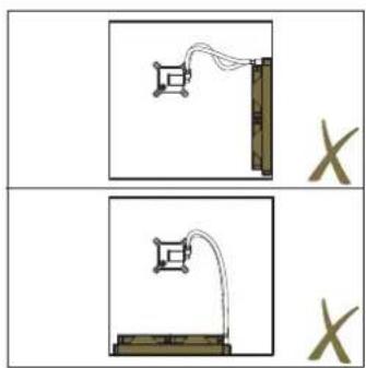
natural_image
Two diagrams showing a vertical structure with a connecting rod and a horizontal support, both labeled 'X' (no text or symbols on the figures themselves)STEP 7: INSTALLING THE ASSEMBLY OF FANS AND THE RADIATOR INTO A PC CASE (AMD)
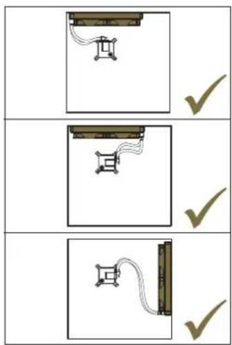
Radiator on top (recommended)
Vertical placement of the radiator with tubing at the bottom (recommended)
Vertical placement of the radiator with tubing at the top (not optimal)
Radiator at the bottom (should be avoided)
text_image
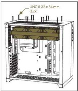
UNC 6-32 x 34 mm (12x)Option 1
Use the UNC 6-32 x 34mm screws to attach the preassembled radiator-and-fans setup with the remaining three fans (to have six fans in total) to the PC chassis.
The orientation of the fans is crucial for achieving the best performance of the radiator.
Install the fans so that they will push the air through the radiator. To be sure about the fan orientation, you can look at the position of the EK logo on the side of the fan - it must be oriented the same way on both the upper and lower set of fans. It is also recommended that cables of all fans are facing the same direction for easier cable management.
Option 2
If there is not enough space inside your PC chassis to place all six fans on the radiator, you may position the remaining three somewhere else inside your PC.
In that case, use the UNC 6-32 x 6mm screws to attach the preassembled radiator and the fans to the PC chassis.
text_image
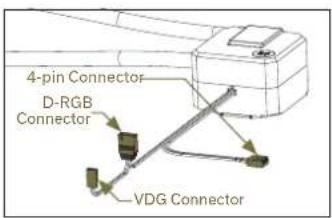
4-pin Connector D-RGB Connector VDG ConnectorSTEP 8: PUMP - CONNECTING CABLES (AMD)
natural_image
Diagram showing a mechanical assembly with a component being inserted into a housing, surrounded by storage tanks (no text or symbols visible)Step A:
Plug the 4-pin PWM connector of the pump into the motherboard
Do not use the same HUB that fans are connected to the rotational speed (RPM) of the fan and the pump should be regulated separately.
text_image
D-RGB Header RGB Header D-RGB Header (7x) HUB 4-pin PWM Header (7x) SATA 4-pin "Red" PWM Header PWM Header to Motherboard (1x) D-RGB Header to Motherboard (1x)Step B:
Plug the 3-pin connector of the pump's D-RGB LED light into the D-RGB HEADER on the motherboard or into one of the D-RGB (Addressable RGB) HEADERS on the HUB The LEDs will work if the pin layout on the header is as follows: +5V, Data, Empty, Ground. With some motherboards, you can alternatively use a VDG connector instead of the D-RGB to connect the LEDs.

Please ensure that the arrow indicated on the connector is plugged into the 15V line as indicated on your motherboard you put LED Diode to the 12V RGB HEADER you can damage the LEDs.

Connector is the same on D-RGB and RGB versions, but D-RGB version has 3 cables from connector to PCB; RGB version has 4 cables. If you connect D-RGB led to ordinary RGB header you can damage your motherboard or LED strip.
text_image
Fan D-RGB LED Light Connector Fan ConnectorSTEP 9: FANS - CONNECTING CABLES (AMD)
text_image
REEM RT0 Fan ConnectorStep A:
Plug all of the 4-pin PWM fan connectors into PWM headers on the HUB (6x). Make sure the red PWM header on the HUB is always used.
Plug the PWM connector from the HUB directly into the CPU fan header on the motherboard. Always use the CPU fan header if possible.
text_image
D-RGB Header RGB HeaderStep B:
Plug the D-RGB connectors of the fans into the D-RGB HEADERS on the HUB (6x)
Plug the D-RGB connector from the HUB directly into the motherboard.
text_image
Non-abrasive cloth IHSOPTIONAL STEP! APPLYING THE THERMAL COMPOUND
This step is relevant only in the case of second installation of AlO or if you damaged the pre-applied paste on the backside of the pump unit! For the first installation, you don't need to apply the additional thermal compound to the CPU's contact surface!
Wipe the CPU's contact surface (using a non-abrasive cloth or a Q-tio as shown in the sample image). On a clean IHS, apply a line of thermal compound and spread it over the whole CPU heat spreader (IHS) with a credit card or something similar.
7. SUPPORT AND SERVICE
For assistance please contact: http://support.ekwb.com/
EKWB d.o.o.
Pod lipami 18
1218 Komenda
Slovenia - EU
8. SOCIAL MEDIA

EKWaterBlocks

@EKWaterBlocks

ekwaterblocks

EKWBofficial

ekwaterblocks
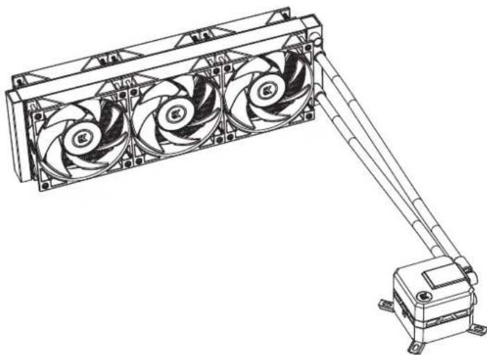
EK-AIO Elite Aurum 360 D-RGB
natural_image
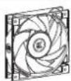
Technical line drawing of a three-blade fan assembly mounted on a base-mounted device (no text or symbols visible)EK-Vardar S 120ER D-RGB (6x)
Eine Tube Wärmelcitpaste (3830046998446 - EK-TIM Ectotherm (1g)) (1x)
Montagesatz (1x)
text_image
Diagram showing five sequential experimental setups with checkmarks and X marks indicating condition or status.text_image
UNC 6-32 x 34 mm (12x)Option 1
natural_image
Diagram of a mechanical assembly with a component and parts, no visible text or symbolsSchritt A
SCHRITT 6: INSTALLATION DER PUMPENEINHEIT (AMD)
text_image
UNC 6-32 x 34 mm (12x)Option 1
natural_image
Diagram of a mechanical assembly with a component and parts, no visible text or symbolsSchritt A
natural_image
Technical line drawing of a mechanical device with three fans and a connected arm (no text or symbols)EK-Vardar S 120ER D-RGB (6x)
Un tubo de pasta térmica (3830046998446 - EK-TIM Ectotherm (1 g)) (1x)
Kit de montaje (1x)
text_image
Diagram showing four sequential experimental setups with checkmarks and X marks indicating condition or measurement.text_image
UNC 6-32 x 34 mm (12x)Opción 1
natural_image
Diagram of a mechanical assembly with a component and parts, no visible text or symbolsPaso A:
Using Philips-head screwdriver, remove the 4 UNC 6-32 screws securing the original plastic hold-down clamps around the socket as shown in the image. Keep the original AMD® backplate and remove the hold-down clamps to store them away. See the image for further part identification.
text_image
UNC 6-32 x 34 mm (12x)Opción 1
natural_image
3D diagram of a mechanical assembly with a component and parts, no visible text or symbolsPaso A:
natural_image
Technical line drawing of a three-blade fan assembly mounted on a base-mounted device (no text or symbols visible)EK-Vardar S 120ER D-RGB (6x)
text_image
Diagram showing four sequential experimental setups with checkmarks and X marks indicating condition or measurement.text_image
UNC 6-32 x 34 mm (12x)Option 1
natural_image
Diagram of a mechanical assembly with a brown component and a downward arrow indicating motion (no text or symbols)Étape A:
ÉTAPE 6: FIXATION DE LA POMPE (AMD)
text_image
UNC 6-32 x 34 mm (12x)Option 1
natural_image
Diagram showing a mechanical component being inserted into a container, with no visible text or symbols.Étape A:
natural_image
Technical line drawing of a mechanical device with three fans and a connected arm (no text or symbols)EK-Vardar S 120ER D-RGB (6個)
text_image
Diagram showing four sequential experimental setups with checkmarks and X marks indicating condition or measurement.text_image
UNC 6-32 x 34 mm (12x)オプション1
natural_image
Diagram showing a mechanical assembly with a component being inserted into a housing, no text or symbols presentステップA
text_image
Diagram showing three identical setups with a device, each checked by a green checkmark.上部にラジエーター(推奨)
natural_image
Two diagrams showing a vertical structure with a connecting rod and a horizontal base, both labeled 'X' (no text or symbols on the figures themselves)text_image
UNC 6-32 x 34 mm (12x)natural_image
Diagram of a mechanical assembly with a component being inserted into a housing, showing no text or symbols.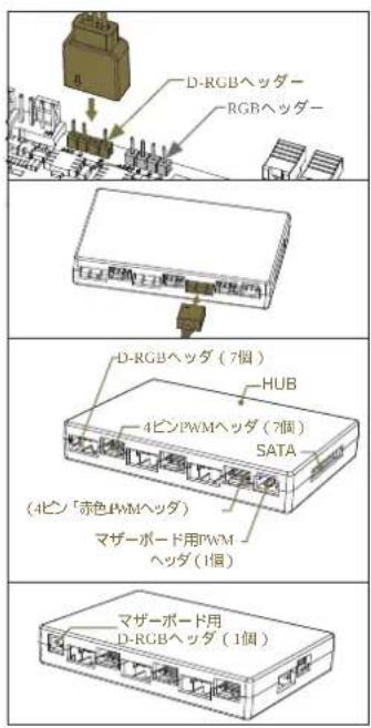
natural_image
Technical line drawing of a mechanical device with three fans and a connected arm (no text or symbols)3. INCLUÍDO NESTE PACOTE
EK-AIO Elite Aurum 360 D-RGB (1x)
EK-Vardar S 120ER D-RGB (6x)
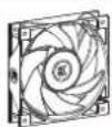
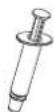
Um tubo de Pasta Térmica (3830046998446 - EK-TIM Ectotherm (1g)) (1x)
Kit de Montagem (1x)
Parafuso Cabeça Phillips UNC 6-32 x 6mm (12x / 8x)

Parafuso Cabeça Phillips UNC 6-32 x 34 mm (comprimento da rosca 5 mm) (12x / 8x)

Porca de aperto manual (Intel/AMD) 4x

PASSO 1: REMOVER A PLACA PRINCIPAL
PASSO 5: REMOVER A PELÍCULA PROTETORA DA COLD-PLATE
Remover a película protetora da parte de trás da unidade da bomba, que se destina a evitar danifi car a cold-plate o o composto térmico pré-aplicado na cold-plate.
text_image
UNC 6-32 x 34 mm (12x)Opção 1
text_image
Conetor 4-pin Conetor D-RGB Conetor VDGnatural_image
3D diagram of a mechanical assembly with a component and parts, no visible text or symbolsPasso A:
text_image
UNC 6-32 x 34 mm (12x)Opção 1
text_image
Conetor 4-pin Conetor D-RGB Conetor VDGnatural_image
Diagram showing a mechanical assembly with a component and parts, no visible text or symbolsPasso A:
natural_image
Technical line drawing of a mechanical device with three fans and a connected arm (no text or symbols)text_image
Bentiator Radiator UNC 6-37 x 30 mmtext_image
Diagram showing four sequential experimental setups with checkmarks and X marks indicating condition or measurement.text_image
UNC 6-32 x 34 mm (12x)Вариант 1
text_image
4-pin Connector D-RGB Connector VDG ConnectorШАГ 9: НАСОС -
natural_image
Diagram of a mechanical assembly with a component and parts, no visible text or symbolsWar A:
text_image
Diagram showing three identical setups with a device, each marked with a checkmark and a schematic diagram.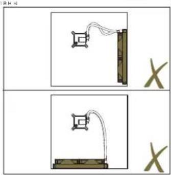
natural_image
Two diagrams showing a mechanical setup with a vertical rod and connected tubing, both labeled 'X' (no text or symbols on the diagrams themselves)text_image
UNC 6-32 x 34 mm (12x)Вариант 1
text_image
4-pin Connector D-RGB Connector VDG ConnectorШАГ 8: НАСОС -
natural_image
Diagram of a mechanical assembly with a component and parts, no visible text or symbolsWar A:
natural_image
Technical line drawing of a three-blade fan assembly mounted on a base-mounted device (no text or symbols visible)text_image
Diagram showing four sequential experimental setups with checkmarks and X marks indicating condition or measurement.text_image
UNC 6-32 x 34 mm (12x)选项1
natural_image
Diagram of a mechanical assembly with a component being inserted into a housing (no text or symbols visible)步骤A
将泵的4针PWM连接器插入主板。