DW719 - Saw DEWALT - Free user manual and instructions
Find the device manual for free DW719 DEWALT in PDF.

User questions about DW719 DEWALT
0 question about this device. Answer the ones you know or ask your own.
Ask a new question about this device
Download the instructions for your Saw in PDF format for free! Find your manual DW719 - DEWALT and take your electronic device back in hand. On this page are published all the documents necessary for the use of your device. DW719 by DEWALT.
USER MANUAL DW719 DEWALT
text_image
Technical diagram of a mechanical device with numbered components for identificationA1
text_image
Technical diagram of a mechanical device with numbered components for identificationA2

natural_image
Technical line drawing of a mechanical device with labeled parts (10 and 6), no readable text or symbols beyond labels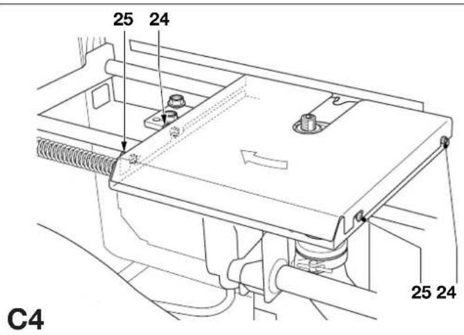
text_image
25 24 C4 25 24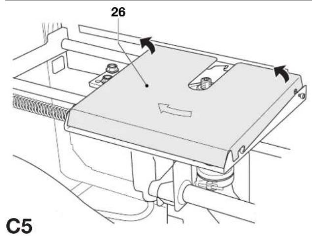
text_image
26 C5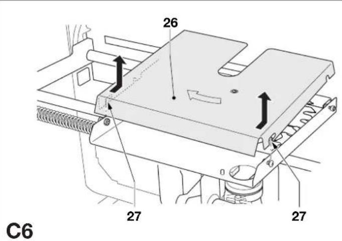
text_image
26 27 27 C6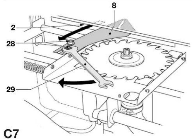
text_image
2 28 8 29 C7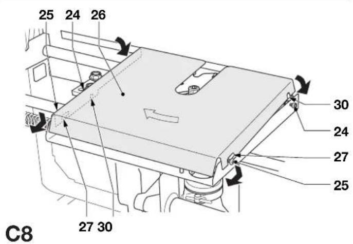
text_image
25 24 26 30 24 27 25 27 30 C8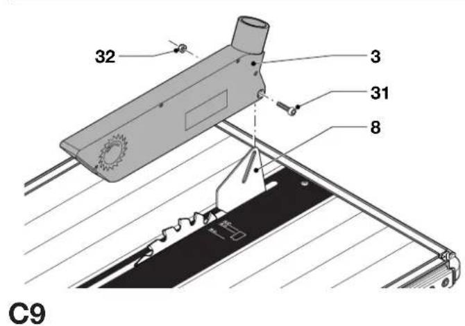
text_image
32 3 31 8 C9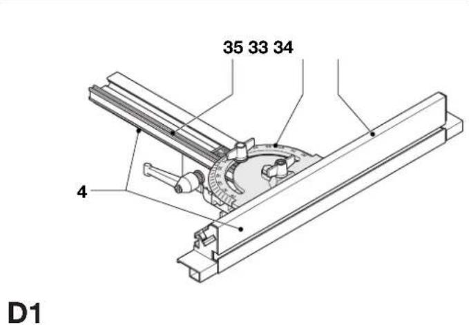
text_image
35 33 34 4 D1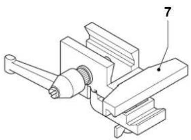
natural_image
Technical line drawing of a mechanical assembly with labeled parts (no text or symbols present)D2
text_image
36 37 33 34 D3D3
text_image
343733 38D4
text_image
343733 39D5
text_image
40 7 42 41D6
text_image
34 37 33 41D7
natural_image
Technical line drawing of a mechanical assembly with gears and shafts (no text or symbols)D8
text_image
4 36E1
text_image
33 E2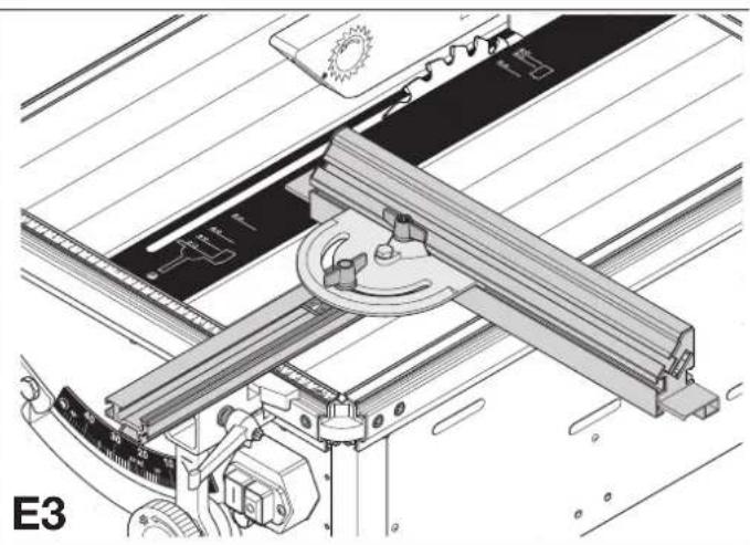
natural_image
Technical line drawing of a mechanical assembly with no visible text or symbols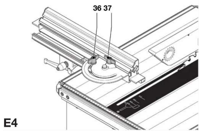
text_image
36 37 E4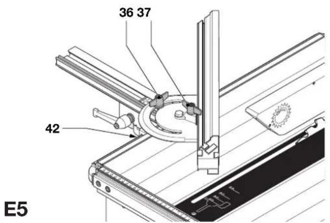
text_image
36 37 42 E5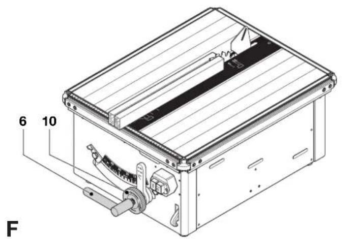
text_image
6 10 F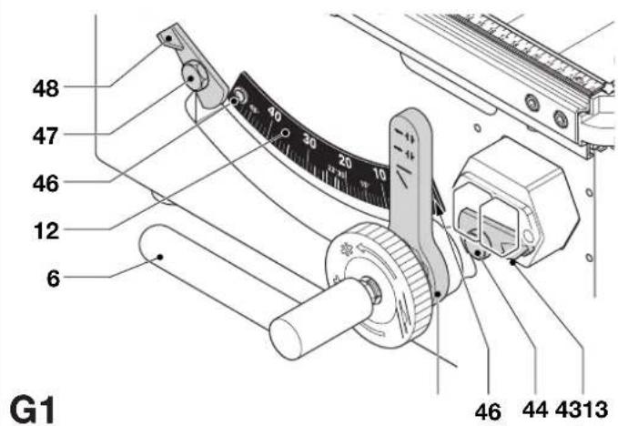
text_image
48 47 46 12 6 G1 46 44 4313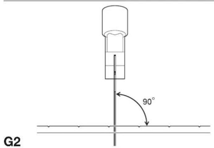
text_image
G2 90°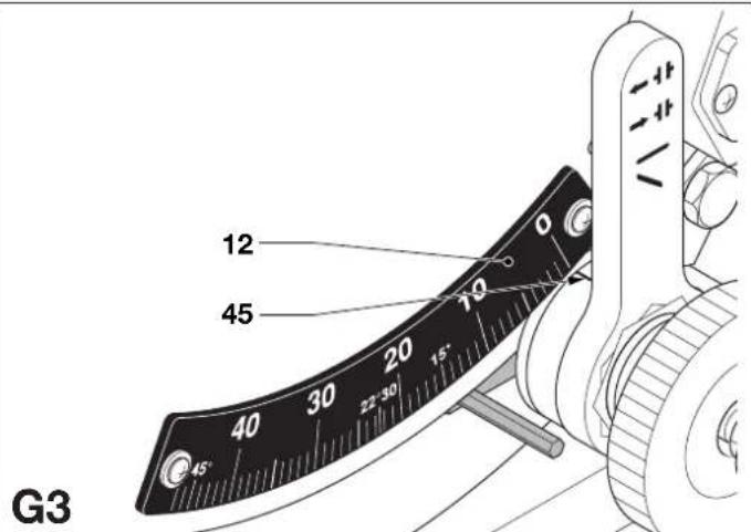
text_image
12 45 40 30 20 15° 45° G3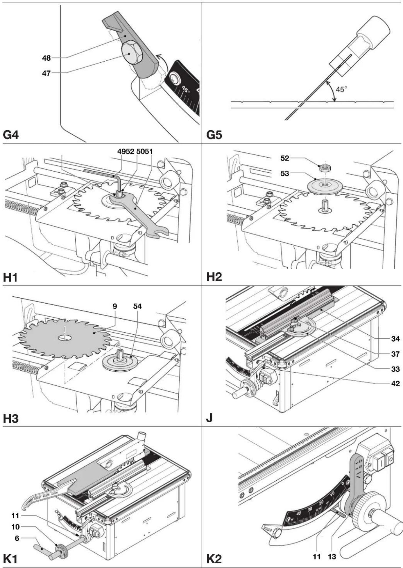
text_image
K3 10 6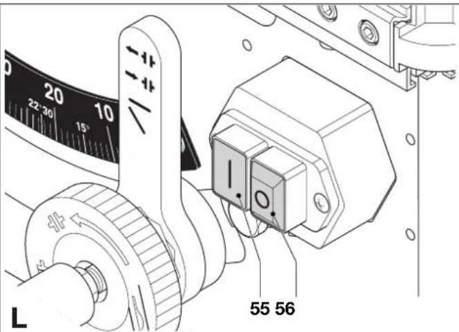
text_image
22°30' 15' 10 - + - - - - - - - - - - - - - - - - - - - - - - - - - - - - - - - - - - - - - - - - - - - - - - - - - - - - - - - - - - - - - - - - - - - - - - - - - - - - - - - - - - - - - - - - - - - - - - - - - - - -55 56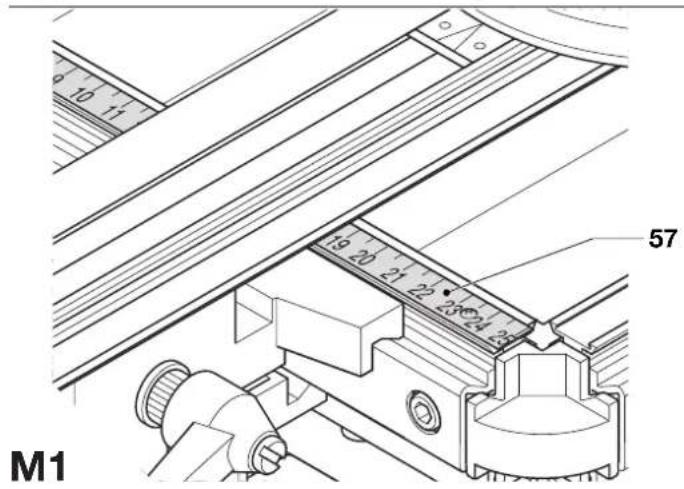
text_image
10 11 57 19 20 21 22 23 24 25 M1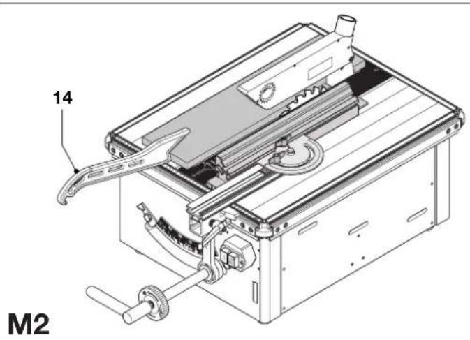
text_image
14 M2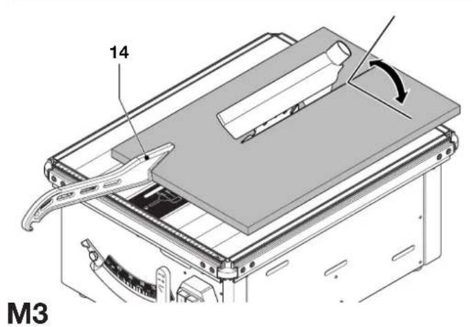
text_image
14 M3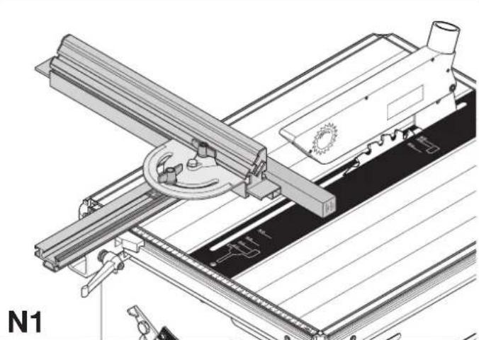
natural_image
Technical line drawing of a mechanical assembly with no visible text or symbols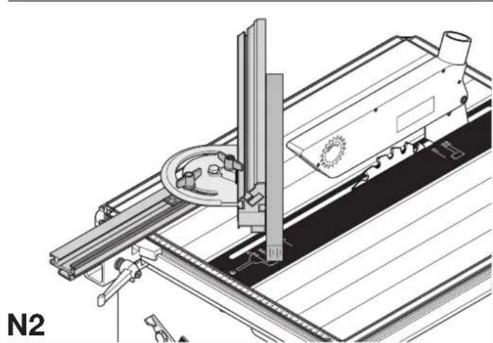
natural_image
Technical line drawing of a mechanical assembly with no visible text or symbols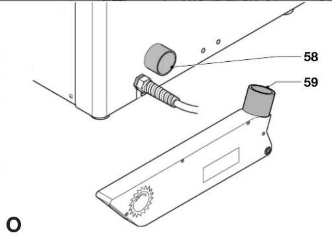
text_image
58 59 O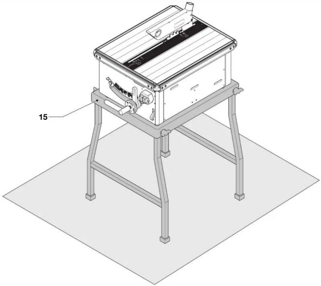
natural_image
Isometric line drawing of a mechanical device with labeled part '15' (no text or symbols on the device itself)P1
text_image
Technical diagram of a mechanical assembly with labeled parts 16 and 17, showing components like a tray, workpiece, and mounting bracket.P2
text_image
Technical diagram of a mechanical assembly with labeled parts 16 and 18P3
Tillykke!
Product and Safety GmbH (TRPS)
Am Grauen Stein 1
D-51105 Köln
Germany
| Cert. No. | |
| BM 2011163 |
Produktudviklingsdirektor
Horst Großmann
X. Jopsmann
Product and Safety GmbH (TRPS)
Am Grauen Stein 1
D-51105 Köln
Germany
You have chosen a DeWALT Power Tool. Years of experience, thorough product development and innovation make DeWALT one of the most reliable partners for professional Power Tool users.
Technical data
| DW719 | |
| Voltage V 230 | |
| Motor power (input) W 1,000 | |
| Blade diameter mm 215 - 225 | |
| Blade arbor size mm 30 | |
| Max. blade thickness mm 2.6 | |
| Max. blade speed min | ^-1 2,950 |
| Automatic blade brake time s < 10 | |
| Table size mm 644 x 514 | |
| Weight kg 28 | |
Cutting capacities
| Blade diameter mm 215 225 | ||
| Depth of cut at 90° mm 47.5 52 | ||
| Depth of cut at 45° mm 33.5 37 | ||
| Max bevel angle | -2 - 47 | -2 - 47 |
| Max. cross-cut capacity on traverse | mm 47.5 x 260 | 52 x 270 |
| Max traverse length on depth of cross-cut | 395 x 20 | 400 x 20 |
Standard equipment:
TCT blade, guard, combined rip/mitre fence, push stick
| Fuses: | ||
| Europe | 230 V tools | 10 Amperes, mains |
| U.K. & Ireland | 230 V tools | 13 Amperes, in plugs |
The following symbols are used throughout this manual:

Denotes risk of personal injury, loss of life or damage to the tool in case of non-observance of the instructions in this manual.

Denotes risk of electric shock.

Sharp edges.
EC-Declaration of conformity

DW719
DeWALT declares that these Power Tools have been designed in compliance with: 98/37/EEC, 89/336/EEC, EN 61029, EN 55014-2, EN 55014, EN 61000-3-2 & EN 61000-3-3.
For more information, please contact DEWALT at the address below or refer to the back of the manual.
Level of sound pressure according to 86/188/EEC & 98/37/EEC, measured according to EN 61029:
| DW719 | |||
| L_pa | (sound pressure) | dB(A)* | 85.5 |
| L_ua | (acoustic power) | dB(A) | 98.5 |
* at the operator's ear

Take appropriate measures for the protection of hearing if the sound pressure of 85 dB(A) is exceeded.
TÜV Rheinland
Product and Safety GmbH (TRPS)
Am Grauen Stein 1
D-51105 Köln
Germany
| Cert. No. | |
| BM 2011163 |
Director Engineering and Product Development Horst Großmann
X. fopsmann
D-65510, Idstein, Germany
Safety instructions
When using Power Tools, always observe the safety regulations applicable in your country to reduce the risk of fire, electric shock and personal injury. Read the following safety instructions before attempting to operate this product. Keep these instructions in a safe place!
General
1 Keep work area clean
Cluttered areas and benches can cause accidents.
2 Consider work area environment
Do not expose Power Tools to humidity. Keep work area well lit. Do not use Power Tools in the presence of flammable liquids or gases.
3 Guard against electric shock
Prevent body contact with earthed surfaces (e.g. pipes, radiators, cookers and refrigerators). For use under extreme conditions (e.g. high humidity, when metal swarf is being produced, etc.) electric safety can be improved by inserting an isolating transformer or a (FI) earth-leakage circuit-breaker.
4 Keep children away
Do not let children come into contact with the tool or extension cord. Supervision is required for those under 16 years of age.
5 Extension cords for outdoor use
When the tool is used outdoors, always use extension cords intended for outdoor use and marked accordingly.
6 Store idle tools
When not in use, Power Tools must be stored in a dry place and locked up securely, out of reach of children.
7 Dress properly
Do not wear loose clothing or jewellery. They can be caught in moving parts. Preferably wear rubber gloves and non-slip footwear when working outdoors. Wear protective hair covering to keep long hair out of the way.
8 Wear safety goggles
Also use a face or dust mask in case the operations produce dust or flying particles.
9 Beware of maximum sound pressure
Take appropriate measures for the protection of hearing if the sound pressure of 85 dB(A) is exceeded.
10 Secure workpiece
Use clamps or a vice to hold the workpiece. It is safer and it frees both hands to operate the tool.
11 Do not overreach
Keep proper footing and balance at all times.
12 Avoid unintentional starting
Do not carry the plugged-in tool with a finger on the switch. Be sure that the switch is released when plugging in.
13 Stay alert
Watch what you are doing. Use common sense. Do not operate the tool when you are tired.
14 Disconnect tool
Shut off power and wait for the tool to come to a complete standstill before leaving it unattended. Unplug the tool when not in use, before servicing or changing accessories.
15 Remove adjusting keys and wrenches
Always check that adjusting keys and wrenches are removed from the tool before operating the tool.
16 Use appropriate tool
The intended use is described in this instruction manual. Do not force small tools or attachments to do the job of a heavy-duty tool. The tool will do the job better and safer at the rate for which it was intended.
Warning! The use of any accessory or attachment or performance of any operation with this tool, other than those recommended in this instruction manual may present a risk of personal injury.
17 Do not abuse cord
Never carry the tool by its cord or pull it to disconnect from the socket. Keep the cord away from heat, oil and sharp edges.
18 Maintain tools with care
Keep the tools in good condition and clean for better and safer performance. Follow the instructions for maintenance and changing accessories. Inspect the tool cords at regular intervals and, if damaged, have them repaired by an authorized DeWALT repair agent. Inspect the extension cords periodically and replace them if damaged. Keep all controls dry, clean and free from oil and grease.
19 Check for damaged parts
Before using the tool, carefully check it for damage to ensure that it will operate properly and perform its intended function. Check for misalignment and seizure of moving parts, breakage of parts and any other conditions that may affect its operation. Have damaged guards or other defective parts repaired or replaced as instructed.
Do not use the tool if the switch is defective. Have the switch replaced by an authorized DEWALT repair agent.
20 Have your tool repaired by an authorized DEWALT repair agent
This Power Tool is in accordance with the relevant safety regulations. To avoid danger, electric appliances must only be repaired by qualified technicians.
Additional safety rules for saw benches
- Make sure that the blade rotates in the correct direction and that the teeth are pointing to the front of the saw bench.
- Be sure all clamp handles are tight before starting any operation.
- Be sure all blade and flanges are clean and the recessed sides of the collar are against the blade. Tighten the arbor nut securely.
- Keep the saw blade sharp and properly set.
- Make sure that the riving knife is adjusted to the correct distance from the blade - maximum 5 mm.
- Never operate the saw without the upper and lower guards in place.
- Keep your hands out of the path of the saw blade.
- Disconnect the saw from the mains supply before changing blades or carrying out maintenance.
- Use a push stick at all times, and ensure that you do not place hands closer than 150 mm from the saw blade while cutting.
- Do not attempt to operate on anything but the designated voltage.
- Do not apply lubricants to the blade when it is running.
- Do not reach around behind the saw blade.
- Never place either hand in the blade area when the saw is connected to the electrical power source.
- Replace the table insert when worn.
- During transportation make sure that the upper part of the saw blade is covered, e.g. by the guard.
- Do not use the guard for handling or transportation.
- Use a holder or wear gloves when handling a saw blade.
- Do not use blades of larger or smaller diameter than recommended. For the proper blade rating refer to the technical data. Use only the blades specified in this manual, complying with EN 847-1.
- Consider applying specially designed noise-reduction blades.
- Do not use HSS blades.
- Do not use cracked or damaged saw blades.
- Do not use any abrasive discs.
- Do not cut ferrous metals, non-ferrous metals or masonry.
Residual risks
The following risks are inherent to the use of saws:
- injuries caused by touching the rotating parts
In spite of the application of the relevant safety regulations and the implementation of safety devices, certain residual risks cannot be avoided.
These are:
- Impairment of hearing.
- Risk of accidents caused by the uncovered parts of the rotating saw blade.
- Risk of injury when changing the blade.
- Risk of squeezing fingers when opening the guards.
- Health hazards caused by breathing dust developed when sawing wood, especially oak, beech and MDF.
Package contents
The package contains:
1 Partly assembled machine
1 Box containing:
1 Combined rip and mitre fence
1 Fence bracket
1 Riving knife
1 Upper blade guard
1 Push stick
1 Spanner 13/17 mm
1 Spanner 20/22 mm
1 Allen key 4 mm
1 Allen key 5 mm
1 Instruction manual
1 Exploded drawing
- Check for damage to the tool, parts or accessories which may have occurred during transport.
• Take the time to thoroughly read and understand this manual prior to operation.
Description (fig. A)
Your DW719 saw bench has been designed to saw wood in two different modes to perform the four main sawing operations of ripping, cross-cutting, bevelling and mitring easily, accurately and safely.
Ripping mode
In the ripping mode, the machine is used to perform the standard ripping operation and for sawing wide pieces by manually feeding the workpiece into the blade.
Blade traverse mode
The blade traverse mode is used to perform all cross-cutting and mitring operations in which the workpiece is held stationary and the blade passed through.
A1
1 Table
2 Table insert
3 Upper blade guard
4 Combined rip and mitre fence
5 On/off switch
6 Combined elevating handle and traverse handle
7 Rip and mitre fence guide support bracket
8 Riving knife
9 Saw blade
10 Blade level locking ring
11 Ripping position locating lever
12 Bevel scale
13 Bevel locking handle
14 Push stick
Optional attachments and accessories
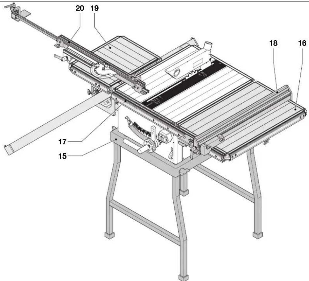
A2
15 Legstand
16 Extension table
17 Scale extension
18 Parallel fence
19 Sliding table
20 Mitre fence
Electrical safety
The electric motor has been designed for one voltage only. Always check that the power supply corresponds to the voltage on the rating plate.
Mains plug replacement (U.K. & Ireland only)
- Should your mains plug need replacing and you are competent to do this, proceed as instructed below. If you are in doubt, contact an authorized DeWALT repair agent or a qualified electrician.
- Disconnect the plug from the supply.
- Cut off the plug and dispose of it safely; a plug with bared copper conductors is dangerous if engaged in a live socket outlet.
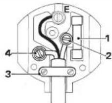
- Only fit 13 Amperes BS1363A approved plugs fitted with the correctly rated fuse (1).
- The cable wire colours, or a letter, will be marked at the connection points of most good quality plugs. Attach the wires to their respective points in the plug (see below). Brown is for Live (L) (2), blue is for Neutral (N) (4) and green/yellow is for Earth (E).
- Before replacing the top cover of the mains plug ensure that the cable restraint (3) is holding the outer sheath of the cable firmly and that the leads are correctly fixed at the terminal screws.
text_image
E 1 2 4 3
Never use a light socket.
Never connect the live (L) or neutral (N) wires to the earth pin marked E or 12
For 115 V units with a power rating exceeding 1500 W, we recommend to fit a plug to BS4343 standard.
Using an extension cable
If an extension cable is required, use an approved extension cable suitable for the power input of this machine (see technical data). The minimum conductor size is 1.5 mm ^2 . When using a cable reel, always unwind the cable completely. Also refer to the table below.
| Conductor size (mm2) Cable rating (Amperes) | |||||||
| 0.75 6 | |||||||
| 1.00 10 | |||||||
| 1.50 15 | |||||||
| 2.50 20 | |||||||
| 4.00 25 | |||||||
| Cable length (m) | |||||||
| 7.5 15 25 30 45 60 | |||||||
| Voltage Amperes Cable rating (Amperes) | |||||||
| 230 | 0 - 2.0 | 6 | 6 | 6 | 6 | 6 | 6 |
| 2.1 - 3.4 | 6 | 6 | 6 | 6 | 6 | 6 | |
| 3.5 - 5.0 | 6 6 | 6 | 6 10 15 | ||||
| 5.1 - 7.0 | 10 10 10 10 15 15 | ||||||
| 7.1 - 12.0 | 15 15 15 15 20 20 | ||||||
| 12.1 - 20.0 | 20 20 20 20 25 | - | |||||
Assembly and adjustment

Prior to assembly and adjustment always unplug the tool.
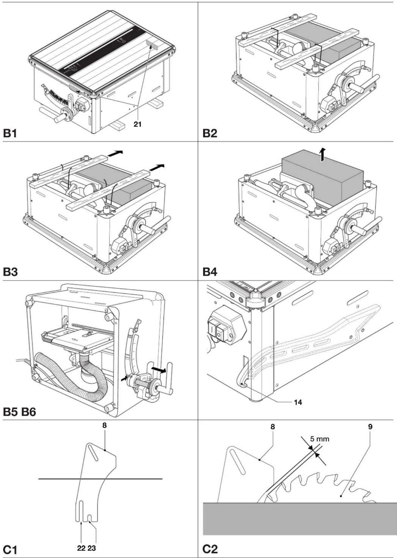
Unpacking the saw and its parts (fig. B1 - B6)
The recesses (19) in the housing have been provided to facilitate transportation (fig. B1).
- Remove the saw from the packaging material carefully.
- Turn the saw upside down (fig. B2).
- Cut the straps holding the shipping blocks to the machine (fig. B3).
- Remove the straps and shipping blocks.
- Pull out the material box (fig. B4).
- With the blade in ripping position i.e. locked in the centre of the table, turn the saw on its side as shown (fig. B5).
- Mount the riving knife (8) as described below.
- Put the saw into the upright position.
- Put the push stick (14) on its place in the slot provided at the front face of the machine (fig. B6).

Always keep the push stick in its place when not in use.
Mounting and adjusting the riving knife (fig. C1 - C8)
The mounting position of the riving knife depends on the blade size: slot (20) to facilitate small blades, slot (21) to facilitate large blades (fig C1).
The correct position is for the body radius of the riving knife (8) to be a maximum of 5mm from the tips of the saw blade teeth (fig. C2).
- With the saw on its side, lower the blade by loosening the blade level locking ring (10) and turning the combined elevating and traverse handle (6) counterclockwise. Retighten the blade level locking ring (fig. C3).
- Loosen the screws (24 & 25) (fig. C4). Remove the blade guard (26) by first lifting the upper part (fig. C5), then sliding the guard forward to clear the open-ended slots (27) for lifting of the lower part (fig. C6).
- Entering from the table top, insert the riving knife (8) into the table insert (2) (fig. C7).
- The riving knife (8) is clamped to a bracket by 13 mm bolts (28). Using the 13 mm spanner (29), loosen the bolts (28) and adjust the position of the riving knife as required.
- Retighten the bolts (28) securely.
- Replace the blade arbor protection guard (26) by first placing the open-ended slots (27) over the screws (25), then sliding the guard rearward to align the recesses (30) for placement over the screws (24) (fig. C8).
• Retighten the screws (24 & 25).
Mounting the upper blade guard (fig. C9)
The upper guard (3) is held in place by one M6 screw and nut.
- With the saw in the upright position, secure the guard to the riving knife using the nut (31) and bolt (32) provided.
- The guard does not need further adjustment. Guided through the slot in the riving knife the guard can move up and down freely, thus always following the exact thickness of the workpiece.
Fitting the combined rip and mitre fence (fig. D1 - D8 & E1 - E6)
Your saw bench is provided with dovetailed grooves on all four sides to accept all accessories and the combined rip and mitre fence.
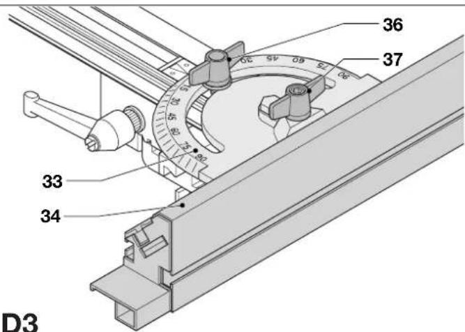
The combined rip and mitre fence (4) is composed of two aluminium profiles joined by a mitre quadrant (33) (fig. D1). The longer profile is the fence (34) and the shorter profile is the fence support (35) which fastens to the fence bracket (7) (fig. D2). The quadrant has locating positions at 0°, 15°, 30°, 45°, 60°, 75° and 90° left and right, and is locked with the quadrant locking knob (36) (fig. D3).
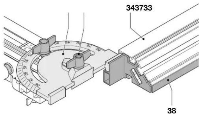
The fence (34) is reversible: the workpiece can be guided along the 80~mm or along the 11mm face to allow the use of a push stick when ripping thin workpieces.
- To set for 11 mm, loosen the fence clamping knob (37) and slide the fence (34) out of the quadrant (33).
- Turn the fence and re-engage the quadrant in the slot as shown (fig. D4). Guide the workpiece along the low face (38).
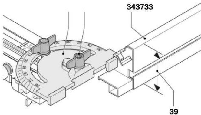
- To use with the full height of 80~mm , slide the fence into the quadrant with the wide face (39) in the vertical position (fig. D5).
Fitting the combined rip and mitre fence for ripping mode (fig. D6 - D8) The combined rip and mitre fence (4) can be used in two different ways to perform this cut.
Bracket on front dovetail: Fence and fence support aligned with blade
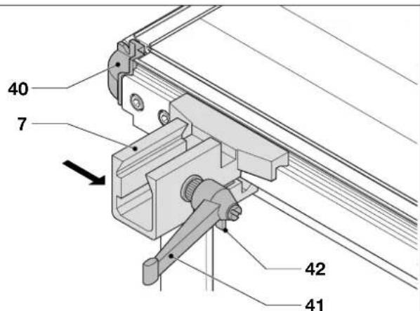
- Present the bracket to the end of the dovetail (40) on the front edge of the table (1) and slide it on as shown (fig. D6).
- Slide the fence support into the fence bracket (7) and lock with the fence support locking knob (41) located at the right-hand side of the fence bracket.
- Slide the fence bracket to the required position and tighten the locking knob (42) located at the bottom side of the fence bracket.
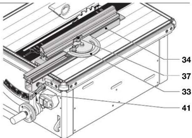
- To adjust the position of the fence, release the fence clamping knob (37) on the mitre quadrant (33) and slide the fence (34) to the required position (fig. D7).
Bracket on right-hand side dovetail:
Fence and fence support at right angles
- Present the bracket with the fence attached to it to the end of the dovetail (40) on the right-hand side of the table (1) and slide it on as shown (fig. D6).
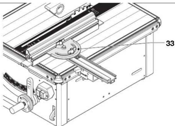
- Set the quadrant (33) at 0^ to align the fence parallel with the blade (fig. D8).
- Check the accuracy by placing the fence against the blade.
- For stability, position the fence bracket and support midway along the length of the fence.
- Tighten the locking knob (42) located at the bottom side of the fence bracket (fig. D6).
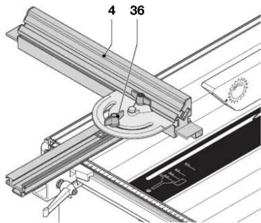
Fitting the fence for blade traverse mode - Cross and mitre cuts (fig. E1 - E5) The combined rip and mitre fence (4) can be used in two different ways to perform cross and mitre cuts.
Bracket on front dovetail: Fence and fence support at right angles
- Install the combined rip and mitre fence in the dovetail on the table front, to the left of the blade (fig. E1).
- Unlock the quadrant locking knob (36) and set the quadrant pointer to 0^ .
- The fence is now at 90^ to the blade and should be positioned to allow the blade to traverse freely past the end.
• Tighten the locking knob (36). - Hold the workpiece against the fence and pull the blade through to perform a cross-cut.
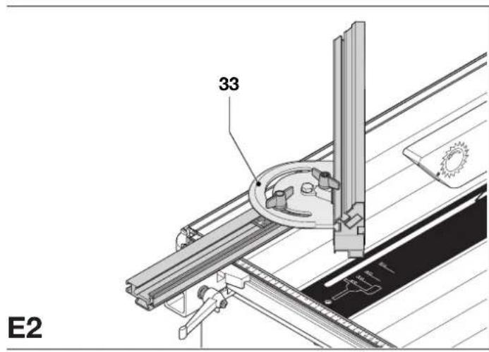
- For mitre cuts, set the required angle on the quadrant (33) (fig. E2).
- To operate the traverse with the left hand, slide the fence bracket along the front of the table, with the fence support retracted (fig. E3), to the right of the blade. Left of the blade is more suitable to operate the traverse with the right hand.

For optimum safety, clamp the workpiece to the fence when cross-cutting.
Bracket on left-hand side dovetail: Fence and fence support aligned
- Unlock and remove the combined rip and mitre fence.
- Slide the complete assembly with the bracket onto the dovetail on the left-hand side of the table (fig. E4).
- Unlock the quadrant locking knob (36) and set the fence to the required angle (fig. E5).
- Re-lock the quadrant locking knob.
- Unlock the fence clamping knob (37) and position the fence to give maximum support. Make sure that the blade will not cut the fence!
- Position the fence at such a distance from the blade that the workpiece to be cross-cut does not touch the blade. Then lock in position with the fence bracket locking knob (42).
Blade height adjustment (fig. F)
The blade can be raised and lowered by turning the combined elevating and traverse handle (6).
- Loosen the blade level locking ring (10) and set the blade to the required height.
- Make sure the top three teeth of the blade are just breaking through the upper surface of the workpiece when sawing. This will ensure that the maximum number of teeth are removing material at any given time, thus giving optimum performance.
- Tighten the locking ring (10).

- For clarity the guard has been lifted in the drawing to show this setting. Before sawing ensure that the guard is in the correct position.
- Once the blade guard touches the table, do not lower the blade any further.
Adjusting the blade angle (fig. G1 - G5)
Right angle adjustment
The machine has an adjustable stop at 0^ for easy right angle adjustment (fig. G1).
- Release the bevel locking handle (13) and set the blade to 0^ , creating a right angle to the table.
- Tighten the bevel locking handle.
- Place a set square on the table and up against the blade (fig. G2).

Do not touch the tips of the blade teeth with the square.
- If adjustment is required, proceed as follows:
- Adjust the eccentric bolt (43) securing the stop (44) to the machine using a 17 mm spanner (fig. G1).
- Once the blade is at a right angle, check that the bevel indicator (45) indicates 0^ on the bevel scale (12) (fig. G3).
- If not, loosen the screws (46), move the scale (12) to read 0^ and tighten the screws (fig. G1).
Blade bevel adjustment
The machine has an adjustable stop at 45^ , and has the facility to cut beyond the stop to 47^ (fig. G4).
- Release the bevel locking handle (13) and bevel the blade to 45^ (fig. G1).
- Tighten the bevel locking handle.
- Check the angle of the blade to the table using a protractor; the angle should be exactly 45^ (fig. G5).
- If required, adjust the eccentric bolt (47) securing the stop (48) to the machine using a 17 mm spanner (fig. G1 & G4).
Replacing the saw blade (fig. B5, C3 - C9 & H1 - H3)

The teeth of a new blade are very sharp and can be dangerous.
- Remove the upper blade guard (3) (fig. C9).
- With the blade in ripping position i.e. locked in the centre of the table, turn the saw on its side as shown (fig. B5).
- Lower the blade by loosening the blade level locking ring (10) and turning the combined elevating and traverse handle (6)
counterclockwise. Retighten the blade level locking ring (fig. C3). - Loosen the screws (24 & 25) (fig. C4). Remove the blade guard (26) by first lifting the upper part (fig. C5), then sliding the guard forward to clear the open-ended slots (27) for lifting of the lower part (fig. C6).
-
Remove the riving knife (8) by loosening the bolts (28) using the 13 mm spanner (29) (fig. C7).
-
Place the 4 mm Allen key (49) into the end of the blade arbor (51) and the 22 mm spanner (50) onto the nut (52) (fig. H1).
- The blade nut has a left-handed thread, therefore holding the Allen key firmly, turn the spanner clockwise to loosen.
- Remove the nut (52) and the outer clamp washer (53) (fig. H2).
- Remove the old blade carefully by easing it off the inner clamp washer (54) (fig. H3).
- Place the new blade (9) onto the inner clamp washer (54), ensuring that the teeth are pointing towards the front of the machine.
- Replace the outer clamp washer (53) which will require rotating to find the correct position (fig. H2).
- Replace the nut (52) and tighten whilst holding the arbor (51) (fig. H1 & H2).
- Replace the riving knife (8) (fig. C7). Tighten the bolts (28) securely.
- Replace the blade arbor protection guard (26) by first placing the open-ended slots (27) over the screws (25), then sliding the guard rearward to align the recesses (30) for placement over the screws (24) (fig. C8).
• Retighten the screws (24 & 25). - Put the saw into the upright position.
- Replace the upper blade guard (3) (fig. C9).
Adjusting the fence parallel to the blade for ripping (fig. J)
- Loosen the fence bracket locking knob (42) and the fence clamping knob (37).
- Slide the complete assembly towards the blade until the fence (34) is just touching the blade.
- Adjust the fence quadrant (33) until the fence is just touching the blade teeth at the front and rear to ensure it is parallel to the blade.
- Tighten the fence bracket locking knob and check that the fence is still parallel.
- Tighten the fence clamping knob (37). The pointer on the quadrant should now read 90^ .

After having used the assembly in the mitre position, re-set the fence for ripping by following the above procedure to ensure accuracy.
Instructions for use

• Always observe the safety instructions and applicable regulations.
- Install the appropriate saw blade. Do not use excessively worn blades. The maximum rotation speed of the tool must not exceed that of the saw blade.
- Do not attempt to cut excessively small pieces.
- Allow the blade to cut freely. Do not force.
- Allow the motor to reach full speed before cutting.
- Make sure all locking knobs and clamp handles are tight.
- The tool is supplied with a 215 mm sawblade. Always use this type of blade when performing ripping applications.
- Never use your saw for freehand cuts!
- Never use your saw for slotting!
- Do not saw warped, bowed or cupped workpieces. There must be at least one straight, smooth side to go against the rip fence or mitre fence.
• Always support long workpieces to prevent kickback.
- Do not remove any cut-offs from the blade area while the blade is running.
The attention of UK users is drawn to the “woodworking machines regulations 1974” and any subsequent amendments.
Ripping mode (fig. K1 & K2)
To perform standard saw bench operations, the blade traverse must be locked in central position.
- Loosen the blade level locking ring (10) (fig. K1).
-
Take hold of the combined elevating and traverse handle (6) and twist it clockwise to release the blade from its locked position at the rear.
-
Push the ripping position locating lever (11) towards the bevel locking handle (13) until the lever locates in the groove in the traverse rod (fig. K2).
- Pull the handle slowly to pull the saw blade across the kerf slot. The ripping position locating lever (11) will engage automatically when the correct blade position is reached. The blade traverse is spring loaded and the spring pressure will retain the blade traverse in this position until manually unlocked (fig. K1).
- After operating, pull back the ripping position locating lever and return the saw blade to the rear position.

Do not allow the saw blade to hit the rear with force. Guide it by keeping hold of the traverse handle.
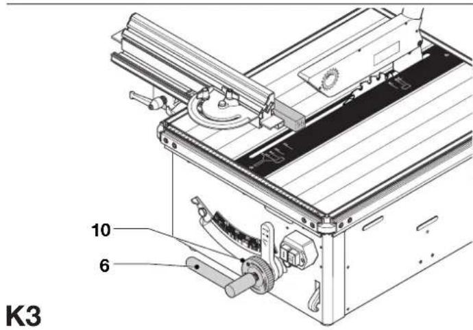
Blade traverse mode (fig. K3)
In this mode, the workpiece is held stationary against the fence and the blade is pulled across to perform the cross-cutting function.
- Release the blade traverse by loosening the blade level locking ring (10) and turning the traverse handle (6) clockwise, thus allowing the blade to be pulled across the workpiece.
- To return the blade traverse to its rest position, simply release the blade traverse handle.
- Tighten the locking ring (10).
Plunge-up function
In the traverse mode the blade may be plunged up through the workpiece, which is clamped in position between the fence and the riving knife, in order to extend the maximum traverse length.
- Release the blade traverse by loosening the blade level locking ring (10) and steadily turning the traverse handle (6) clockwise, thus allowing the blade to cut through the workpiece.
- When the blade has been fully lifted it can be traversed as described above.
Switching on and off (fig. L)
The on/off switch of your saw bench offers multiple advantages:
- no-volt release function: should the power be shut off for some reason, the switch has to be deliberately reactivated.
- motor overload protection device: in case of motor overload, the power supply to the motor will be cut off. If this happens, let the motor to cool for 10 minutes and then press the green start button.
- electronic braking system: after switching off, the braking system will produce a humming noise for about eight seconds as it resets. The machine can be restarted during this period if required.
- To switch the machine on, press the green start button (55).
- To switch the machine off, press the red stop button (56).
Basic saw cuts
Ripping mode (fig. M1 - M3)
Vertical ripping
- Set the blade to 0^ .
- Set the blade in ripping position.
- Set the blade to the required height.
- Mount the fence assembly for ripping mode to the right of the blade, with the rear end of the fence level with the back of the riving knife.
- Check the fence for parallelity to the blade.
- Position the fence using the scale (57) (fig. M1). (The workpiece between the blade and the fence will be the measured and retained section. The scrap or off-cut is to the left of the blade.)
- If using the upper guard in the fixed position, adjust to the height required.
- Switch on the machine.
-
Slowly feed the workpiece underneath the front guard, keeping it firmly pressed against the rip fence. Allow the teeth to cut, and do not force the workpiece through the blade. The blade speed should be kept constant (fig. M2).
-
Remember to use the push stick (14) when close to the blade.
- Switch off the machine after completing the cut.

Always switch off the tool when work is finished and before unplugging.
Bevel ripping
The combined rip and mitre fence can be positioned either to the left or right of the blade (fig. M3).
- Set the required bevel angle.
• Proceed as for vertical ripping.
Blade traverse mode - Cross-cutting (fig. N1 & N2)
Vertical cross-cutting 90° (fig. N1)
- Mount the fence assembly for blade traverse mode.
Remember:
When the fence is to the left of the blade operate the traverse handle with the right hand.
When the fence is to the right of the blade operate the traverse handle with the left hand.
- With the machine switched off, pull the saw blade across to ensure that the fence is definitely not in the path of the blade.
- Mark the workpiece and place it up against the fence with the cutting mark in line with the saw blade.
- Switch on the machine.
- Holding or clamping the workpiece firmly against the fence, pull the blade across the workpiece.
- Ensure a steady and even pull whilst sawing.
- Return the blade to the rear and switch off the machine after completing the cut.
- Mount the fence assembly for blade traverse mode.
Remember:
When the fence is to the left of the blade operate the traverse handle with the right hand.
When the fence is to the right of the blade operate the traverse handle with the left hand.
- Set the fence to the required angle.
• Proceed as for vertical cross-cutting.
Bevel cuts
- Set the required bevel angle.
• Proceed as for vertical cross-cutting.
Compound mitre
This cut is a combination of a mitre and a bevel cut.
- Set the required bevel angle.
• Proceed as for mitre cuts.

Dust extraction (fig. O)
The machine is provided with two dust extraction connection points.
One is situated at the rear of the machine casing (58), and the other is in the upper blade guard (59).
- To provide the best dust extraction results, it is recommended that both points are connected to a suitable dust extraction device during all sawing operations.
- Whenever possible, connect a dust extraction device designed in accordance with the relevant regulations regarding dust emission.
Optional attachments
The attachments, i.e. the legstand (15), extension table (16) with scale extension (17), parallel fence (18), sliding table (19) and mitre fence (20) are available as an option (fig. A2).
Consult your dealer for further information on the appropriate accessories.
Legstand (fig. A2 & P1)
The legstand has been designed for installing your saw bench as a standalone machine acquiring optimum space for using the extension table (16) and/or the sliding table (19) (fig. A2).
- Place the legstand (15) on the floor leaving enough space to use freely any attachment mounted to the machine (fig. P1).
- Place the machine on the legstand making sure that the four feet on the machine are located within the frame.
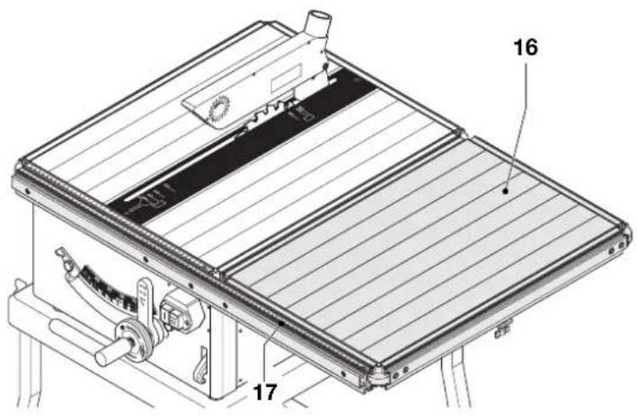
Extension table (fig. A2 & P2)
The extension table (16) utilises the same dovetail system for location and can therefore be fitted onto any side of the table. Along with the table comes a scale extension (17) to provide in optimum measuring facility, for example when it is used in combination with the parallel fence (18) (fig. A2).
- The most suitable position is on the right-hand side of the machine (fig. P2).
- The fence assembly can be used on the extension table in the same way as on the machine table.
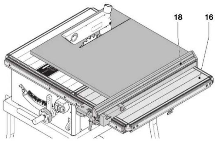
Parallel fence (fig. A2 & P3)
The parallel fence (18) is used in the ripping mode to extend the ripping guidance over the full length of the table (fig. A2).
- The most suitable position is to the right of the blade (fig. P3).
- The parallel fence can be used either on the machine table or on the extension table.
- Adjust the fence parallel to the blade.
- Refer to the instructions for sawing in ripping mode.
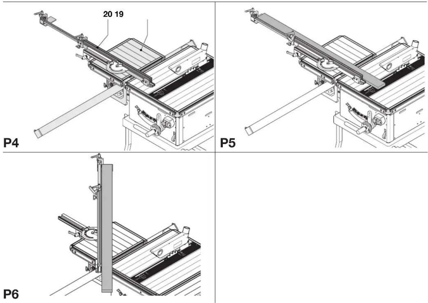
Sliding table and mitre fence (fig. A2 & P4 - P6)
The sliding table (19) and extendable mitre fence with end stop (20) are used in the ripping mode to support cross-cutting long workpieces at any angle from 0^ to 90^ (fig. A2).
- The only suitable position for the sliding table is on the left-hand side of the machine (fig. P4).
- The fence assembly can be used on the sliding table in the same way as on the machine table.
- Replacing the fence profile, the mitre fence can be fitted to the mitre quadrant for enhanced support and guidance. The most suitable position is on the left-hand side of the sliding table.
- Set the blade in ripping position.
- For straight cross-cuts, set the fence at 90^ to the blade (fig. P5).
- For mitre cuts, set the required angle (fig P6).
- Place the workpiece against the mitre fence.
- Before making a cut, check that the fence does not foul the blade and that the workpiece will be cut through.
- Slowly push the table to the rear, thus feeding the workpiece along the blade.
Maintenance
Your D=WALT machine has been designed to operate over a long period of time with a minimum of maintenance. Continuous satisfactory operation depends upon proper tool care and regular cleaning.

Cleaning
Keep the ventilation slots clear and regularly clean the housing with a soft cloth.
- On a weekly basis, remove sawdust from the machine.

Unwanted tools and the environment
Take your tool to an authorized DEWALT repair agent where it will be disposed of in an environmentally safe way.
GUARANTEE
• 30 DAY NO RISK SATISFACTION GUARANTEE •
If you are not completely satisfied with the performance of your DeWALT tool, simply return it within 30 days, complete as purchased, to the point of purchase, for a full refund or exchange. Proof of purchase must be produced.
• ONE YEAR FREE SERVICE CONTRACT •
If you need maintenance or service for your DEWALT tool, in the 12 months following purchase, it will be undertaken free of charge at an authorized DEWALT repair agent. Proof of purchase must be produced. Includes labour and spare parts for the attachments. Excludes accessories.
• ONE YEAR FULL WARRANTY •
If your D≡WALT product becomes defective due to faulty materials or workmanship within 12 months from the date of purchase, we guarantee to replace all defective parts free of charge or, at our discretion, replace the unit free of charge provided that:
• The product has not been misused.
• Repairs have not been attempted by unauthorized persons.
• Proof of purchase date is produced.
This guarantee is offered as an extra benefit and is additional to consumers statutory rights.
For the location of your nearest authorized D≡WALT repair agent, please use the appropriate telephone number on the back of this manual. Alternatively, a list of authorized D≡WALT repair agents and full details on our after-sales service are available on the Internet at
www.2helpU.com.
Product and Safety GmbH (TRPS)
Am Grauen Stein 1
D-51105 Köln
Germany
| Cert. No. | |
| BM 2011163 |
Director Engineering and Product Development Horst Großmann
X. fopsmann
Product and Safety GmbH (TRPS)
Am Grauen Stein 1
D-51105 Köln
Germany
| Cert. No. | |
| BM 2011163 |
Product and Safety GmbH (TRPS)
Am Grauen Stein 1
D-51105 Köln
Germany
Cert. No.
BM 2011163
Product and Safety GmbH (TRPS)
Am Grauen Stein 1
D-51105 Köln
Germany
| Cert. No. | |
| BM 2011163 |
Director Engineering and Product Development Horst Großmann
X. Jopsmann
Product and Safety GmbH (TRPS)
Am Grauen Stein 1
D-51105 Köln
Germany
Director Engineering and Product Development Horst Großmann
X. Jopman
DeWALT, Richard-Klinger-Straße 40, D-65510, Idstein, Tyskland
Sikkerhetsforskrifter
Product and Safety GmbH (TRPS)
Am Grauen Stein 1
D-51105 Köln
Germany
| Cert. No. | |
| BM 2011163 |
Director Engineering and Product Development Horst Großmann
X. Jopsmann
DeWALT, Richard-Klinger-Straße 40, D-65510, Idstein, Alemanha
15 Tire as chaves de aperto
Product and Safety GmbH (TRPS)
Am Grauen Stein 1
D-51105 Köln
Germany
| Cert. No. | |
| BM 2011163 |
Director Engineering and Product Development Horst Großmann
X. fopsmann
Product and Safety GmbH (TRPS)
Am Grauen Stein 1
D-51105 Köln
Germany
| Cert. No. | |
| BM 2011163 |
Director Engineering and Product Development Horst Großmann
X. Jopsmann
Product and Safety GmbH (TRPS)
Am Grauen Stein 1
D-51105 Köln
Almanya
| Vesika numarası | |
| BM 2011163 |
Product and Safety GmbH (TRPS)
Am Grauen Stein 1
D-51105 Köln
Germany
| Cert. No. | |
| BM 2011163 |