DW744XP - Saw DEWALT - Free user manual and instructions
Find the device manual for free DW744XP DEWALT in PDF.

User questions about DW744XP DEWALT
0 question about this device. Answer the ones you know or ask your own.
Ask a new question about this device
Download the instructions for your Saw in PDF format for free! Find your manual DW744XP - DEWALT and take your electronic device back in hand. On this page are published all the documents necessary for the use of your device. DW744XP by DEWALT.
USER MANUAL DW744XP DEWALT
English (original instructions)
text_image
Technical diagram of a mechanical device with numbered parts labeled 13 to 18A2
text_image
19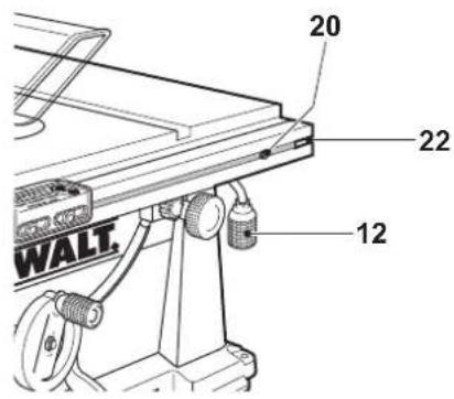
text_image
20 22 12 WALT.A3
text_image
7 13 22 20B1

text_image
2425B2
natural_image
Mechanical diagram showing hands operating a pulley system with a 25-degree angle indicator (no text or symbols present)C1
text_image
27 26C2
text_image
Technical diagram showing mechanical alignment with labeled parts 28 and 29, including a scale ruler and component details.D
text_image
32 31 33 30E
text_image
G 6 34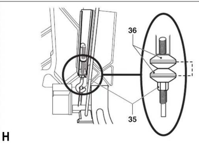
text_image
36 35 H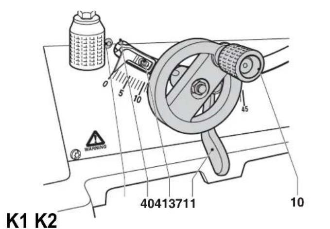
text_image
K1 K2 40413711 10 WARNING 0 5 10 45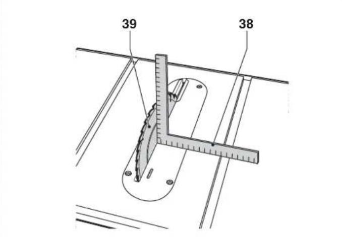
text_image
39 38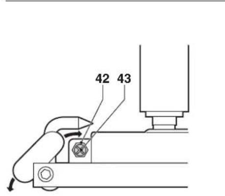
text_image
42 43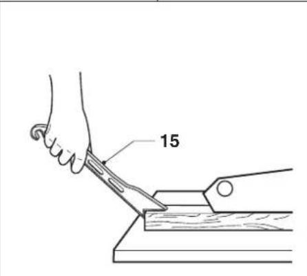
text_image
15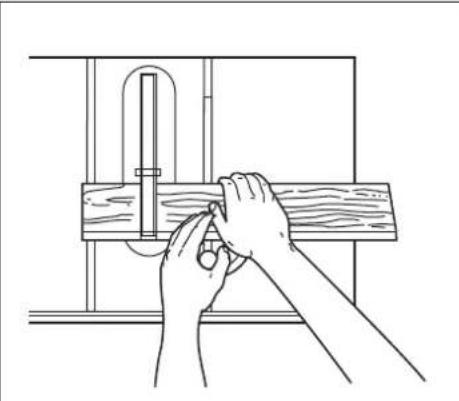
natural_image
Line drawing of hands using a measuring tool to adjust or install a wooden plank (no text or symbols)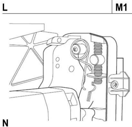
text_image
L M1 N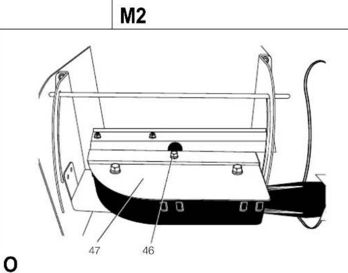
text_image
M2 47 46 OTillykke!
D-65510, Idstein, Germany
01.08.2009
Sicherheitshinweise
You have chosen a DEWALT tool. Years of experience, thorough product development and innovation make DEWALT one of the most reliable partners for professional power tool users.
Technical Data
| DW744 DW744XPLX GB/QS | ||||
| Voltage | V | 115 | 230 | |
| Type | 3/4 | 3 | ||
| Motor power (input) | W | 1,500 | 2,000 | |
| Motor power (output) | W | 850 | 1,300 | |
| No-load speed | min ^1 | 3,650 | 3,000 | |
| Blade diameter | mm | 250 | 250 | |
| Blade bore | mm | 30 | 30 | |
| Blade body thickness | mm | 2.2 | 2.2 | |
| Riving knife thickness | mm | 2.3 | 2.3 | |
| Depth of cut at 90° | mm | 77 | 77 | |
| Depth of cut at 45° | mm | 57 | 57 | |
| Ripping capacity mm | 625 | 625 | ||
| Overall dimensions | mm | 740 x 680 x 465 | 740 x 680 x 465 | |
| Weight | kg | 29 | 29 | |
| L_FA | (sound pressure) | dB(A) | 107 | 105 |
| K_FA | (sound pressure uncertainty) | dB(A) | 3 | 3 |
| L_OA | (sound power) | dB(A) | 92 | 92 |
| K_OA | (sound power uncertainty) | dB(A) | 3 | 3 |
Fuses:
| Europe | 230 V tools | 10 Amperes, mains |
| U.K. & Ireland | 230 V tools | 13 Amperes, in plugs |
| U.K. & Ireland | 115 V tools | 16 Amperes, mains |
NOTE: Switching activity may produce short-term voltage changes or fluctuations. Under unfavourable conditions in public low-voltage supply systems impairment of other appliances might appear. Disturbances will not occur if the impedance is less than 0.25 Ohms. Sockets used for these power tools shall be fused with 16 Amperes cut-out with an inert characteristic.
Definitions: Safety Guidelines
The definitions below describe the level of severity for each signal word. Please read the manual and pay attention to these symbols.

DANGER: Indicates an imminently
hazardous situation which, if not avoided, will result in death or serious injury.

WARNING: Indicates a potentially hazardous situation which, if not avoided, could result in death or serious injury.

CAUTION: Indicates a potentially hazardous situation which, if not avoided, may result in minor or moderate injury.

NOTICE: Indicates a practice not related to personal injury which, if not avoided, may result in property damage.

Denotes risk of electric shock.

Denotes risk of fire.
Sharp edges.
EC-Declaration of Conformity
MACHINERY DIRECTIVE

DW744, DW744XP
DEWALT declares that these products described under "technical data" are in compliance with: 2006/42/EC, EN 61029-1, EN 61029-2-1.
These products also comply with Directive 2004/108/EC. For more information, please contact DEWALT at the following address or refer to the back of the manual.
The undersigned is responsible for compilation of the technical file and makes this declaration on behalf of DEWALT.

text_image
H. JopsmanHorst Grossmann
Vice President Engineering and Product Development
D-65510, Idstein, Germany
01.08.2009
Safety instructions
When using stationary power tools, always observe the safety regulations applicable in your country to reduce the risk of fire, electric shock and personal injury.
Read all of this manual carefully before operating the tool.
Save this manual for future reference.
General
1 Keep work area clean
Cluttered areas and benches can cause accidents.
2 Consider work area environment
Do not expose the tool to rain. Do not use the tool in damp or wet conditions. Keep the work area well lit (250 - 300 Lux). Do not use the tool where there is a risk of causing fire or explosion, e.g. in the presence of fl ammable liquids and gases.
3 Keep children away
Do not allow children, visitors or animals to come near the work area or to touch the tool or the mains cable.
4 Dress properly
Do not wear loose clothing or jewellery, as these can be caught in moving parts. Wear protective hair covering to keep long hair out of the way. When working outdoors, preferably wear suitable gloves and non-slip footwear.
5 Personal protection
Always use safety glasses. Use a face or dust mask whenever the operations may produce dust or flying particles. If these particles might be considerably hot, also wear a heat-resistant apron.
Wear ear protection at all times. Wear a safety helmet at all times.
6 Guard against electric shock
Prevent body contact with earthed or grounded surfaces (e.g. pipes, radiators, cookers and refrigerators). When using the tool under extreme conditions (e.g. high humidity, when metal swarf is being produced, etc.), electric safety can be improved by inserting an isolating transformer or a (FI) earth-leakage circuit-breaker.
7 Do not overreach
Keep proper footing and balance at all times.
8 Stay alert
Watch what you are doing. Use common sense. Do not operate the tool when you are tired.
9 Secure workpiece
Use clamps or a vice to hold the workpiece. It is safer and it frees both hands to operate the tool.
10 Connect dust extraction equipment
If devices are provided for the connection of dust extraction and collection facilities, ensure that these are connected and properly used.
11 Remove adjusting keys and wrenches
Always check that adjusting keys and wrenches are removed from the tool before operating the tool.
12 Extension cables
Before use, inspect the extension cable and replace if damaged.
When using the tool outdoors, only use extension cables intended for outdoor use and marked accordingly.
13 Use appropriate tool
The intended use is described in this instruction manual. Do not force small tools or attachments to do the job of a heavy-duty tool. The tool will do the job better and safer at the rate for which it was intended. Do not force the tool.
WARNING! The use of any accessory or attachment or performance of any operation with this tool other than those recommended in this instruction manual may present a risk of personal injury.
14 Check for damaged parts
Before use, carefully check the tool and mains cable for damage. Check for misalignment and seizure of moving parts, breakage of parts, damage to guards and switches and any other conditions that may affect its operation.
Ensure that the tool will operate properly and perform its intended function. Do not use the tool if any part is damaged or defective. Do not use the tool if the switch does not turn it on and off. Have any damaged or defective parts replaced by an authorised DEWALT repair agent. Never attempt any repairs yourself.
15 Unplug tool
Switch off and wait for the tool to come to a complete standstill before leaving it unattended. Unplug the tool when not in use, before changing any parts of the tools, accessories or attachments and before servicing.
16 Avoid unintentional starting
Be sure that the tool is switched off before plugging in.
17 Do not abuse cord
Never pull the cord to disconnect from the socket. Keep the cord away from heat, oil and sharp edges.
18 Store idle tools
When not in use, tools must be stored in a dry place and locked up securely, out of reach of children.
19 Maintain tools with care
Keep the tools in good condition and clean for better and safer performance. Follow the instructions for maintenance and changing accessories. Keep all handles and switches dry, clean and free from oil and grease.
20 Repairs
This tool is in accordance with the relevant safety regulations. Have your tool repaired by an authorised DEWALT repair agent. Repairs should only be carried out by qualified persons using original spare parts; otherwise this may result in considerable danger to the user.
Additional safety rules for saw benches
- Do not use saw blades with a body thickness greater or a width of tooth smaller than the thickness of the riving knife.
- Make sure that the blade rotates in the correct direction and that the teeth are pointing to the front of the saw bench.
- Be sure all clamp handles are tight before starting any operation.
- Be sure all blade and flanges are clean and the recessed sides of the collar are against the blade. Tighten the arbor nut securely.
- Keep the saw blade sharp and properly set.
- Make sure that the riving knife is adjusted to the correct distance from the blade - maximum 5 mm.
- Never operate the saw without the upper and lower guards in place. - Keep your hands out of the path of the saw blade.
- Disconnect the saw from the mains supply before changing blades or carrying out maintenance.
- Use a push stick at all times, and ensure that you do not place hands closer than 150 mm from the saw blade while cutting.
- Do not attempt to operate on anything but the designated voltage.
- Do not apply lubricants to the blade when it is running.
- Do not reach around behind the saw blade.
• Always keep the push stick in its place when not in use.
• Do not stand on top of the unit.
- During transportation make sure that the upper part of the saw blade is covered, e.g. by the guard.
- Do not use the guard for handling or transportation.

WARNING: This machine is equipped with a specially configured power supply cord (type Y attachment). If the power supply cord is damaged or otherwise defective, it must only be replaced by the manufacturer or by an authorized repair agent.
- Immediately replace the table insert when worn or damaged.
- Check that the workpiece is properly supported. Always provide additional support for long workpieces.
- Do not exert side pressure on the saw blade.
- Never cut light alloy. The machine is not designed for this application.
- Do not use abrasive disc or diamond cutting wheels
- Rebating, slotting or grooving is not allowed.
- In case of an accident or machine failure, immediately switch the machine off and pull the plug. Report the failure and mark the machine in suitable form which prevents that other persons use the defective machine.
- When the saw blade is blocked due to abnormal feed force during cutting, ALWAYS switch the machine off and disconnect from power supply. Remove the workpiece and ensure that the saw blade runs free. Turn the machine on and start a new cutting operation with reduced feed force.
Saw blades
- The max. allowable speed of the saw blade must always be equal to or greater than the no-load speed of the tool specified on the nameplate.
- Do not use saw blades that do not conform to the dimensions stated in the technical data. Do not use any spacers to make a blade fit onto the spindle. Use only the blades specified in this manual, complying with EN 847-1.
- Consider applying specially designed noise-reduction blades.
- Do not use HSS blades.
- Do not use cracked or damaged saw blades.
• Always choose a suitable saw blade for your application.
• Always wear gloves for handling saw blades and rough material. Saw blades should be carried in a holder wherever practicable.
Residual risks
The following risks are inherent to the use of saws:
- injuries caused by touching the rotating parts
In spite of the application of the relevant safety regulations and the implementation of safety devices, certain residual risks cannot be avoided. These are:
- Impairment of hearing.
- Risk of accidents caused by the uncovered parts of the rotating saw blade.
- Risk of injury when changing the saw blade with unprotected hands.
- Risk of squeezing fingers when opening the guards.
- Health hazards caused by breathing dust developed when sawing wood, especially oak, beech and MDF.
The following factors are of influence to noise production:
- the material to be cut
- the type of saw blade
- the feed force
The following factors are of influence to dust exposure:
- worn saw blade
- dust extractor with air velocity less than 20 m/s
- workpiece not exactly guided
Markings on Tool
The following pictograms are shown on the tool:

Read instruction manual before use.

Wear ear protection.

Wear eye protection.

Wear respiratory protection.
Pull the plug from the socket when blade change or any maintenance is needed.

Keep hands away from cutting area and the blade.

Carrying point.
DATECODEPOSITION
The Date Code, which also includes the year of manufacture, is printed into the housing.
Example:
2011 XX XX
Year of Manufacture
Package contents
The package contains:
1 Partly assembled machine
1 Rip fence
1 Mitre gauge
1 Saw blade
1 Upper blade guard assembly
1 Table insert
1 Blade wrench
1 Arbor wrench
1 Dust extraction adapter
1 Instruction manual
1 Exploded drawing
- Check for damage to the tool, parts or accessories which may have occurred during transport.
• Take the time to thoroughly read and understand this manual prior to operation.
Description (fi g. A1 - A3)
A1
1 On/off switch
2 Mounting holes
3 Hand indentation
4 Table
5 Upper blade guard
6 Table insert
7 Rip fence
8 Rip scale indicator
9 Fine adjustment knob
10 Combined elevating and bevel control wheel
11 Bevel lock lever
12 Ripping position lock lever
A2
13 Rip fence latch
14 Dust extraction adapter
15 Push stick
16 Fence profi le
17 Locking knobs
18 Fence slot
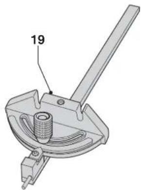
A3
19 Mitre gauge
INTENDED USE
Your DW744XP/DW744-LX jobsite table saw has been designed to perform the sawing operation of ripping, cross-cutting, bevelling and mitring in wood, wood products and plastics. This unit is designed for use with a 0 250 mm carbide tip blade.

WARNING: Do not use the machine for other purposes as intended.
DO NOT use under wet conditions or in presence of flammable liquids or gases.
These table saws are professional power tools.
DO NOT let children come into contact with the tool. Supervision is required when inexperienced operators use this tool.
Electrical safety
The electric motor has been designed for one voltage only. Always check that the power supply corresponds to the voltage on the rating plate.

WARNING: 115 V units have to be operated via a fail safe isolating transformer with an earth screen between the primary and secondary winding.
If the supply cord is damaged, it must be replaced by a specially prepared cord available through the DEWALT service organisation.
Mains Plug Replacement (U.K. & Ireland Only)
If a new mains plug needs to be fitted:
• Safely dispose of the old plug.
- Connect the brown lead to the live terminal in the plug.
- Connect the blue lead to the neutral terminal.

WARNING: No connection is to be made to the earth terminal.
Follow the fitting instructions supplied with good quality plugs.
Recommended fuse: 13 A.
FITTING A MAINS PLUG TO 115 V UNITS
The plug should be fitted by a competent person. If you are in doubt, contact an authorized DEWALT repair agent or qualified electrician.
The plug fitted should be comply with BS EN 60309 (BS4343), 16Amps, earthing contact position 4h.
Using an extension cable
If an extension cable is required, use an approved extension cable suitable for the power input of this machine (see technical data).
The minimum conductor size is 2.5 mm ^4 .
When using a cable reel, always unwind the cable completely.
Assembly and adjustment

WARNING: Prior to assembly and adjustment always unplug the tool.
Unpacking
- Remove the saw from the packaging material carefully.
- The machine is fully assembled except for the blade, rip fence, upper blade guard and table insert.
- Finalise the assembly following the instructions as described below.
- Put the push stick (15) on its place over the threaded end provided at the right-hand side of the machine (fi g. A2).

WARNING: Always keep the push stick in its place when not in use.
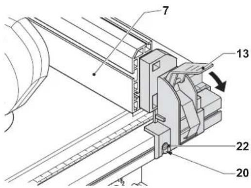
Fitting the Rip Fence (Fig. B1, B2)
The rip fence (7) can be installed on the left or right side of your table saw.
- Align the locator screw (20) on the fence rail with the fence head slot and align the latch (13) with the opening (22) (fig. B1, B2).
- Secure the rip fence by snapping the latches onto the rails as shown in figure B2. Be sure to snap both front and rear latches in place.
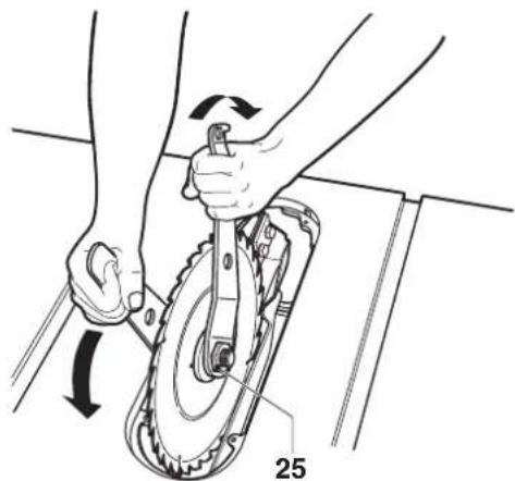
Mounting the saw blade (fi g. A1, C1 & C2)

WARNING: Ensure the machine is disconnected from the power source.

WARNING: The teeth of a new blade are very sharp and can be dangerous.

WARNING: The saw blade MUST be replaced as described in this section. ONLY use saw blades as specified under Technical Data. We suggest DT4226. NEVER fit other saw blades.
- Raise the blade arbor to its maximum by rotating the control wheel (10) clockwise (fi g. A1).
- Place the saw blade onto the spindle in the order shown in figure C1. The outer flange (24) has a 30 mm raised boss which fits inside the blade bore. Make sure the teeth point down at the front of the table.
- Hold the spindle using the open-ended wrench and tighten the arbor nut (25) by rotating clockwise using the arbor wrench (fi g. C2).
• To remove the blade, proceed in reverse order.

WARNING: Always check the rip fence pointer and the riving knife after having changed the blade.
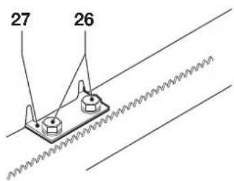
Parallel adjustment (fi g. A2 & D)
For optimum performance, the blade must be parallel to the mitre slots. This adjustment has been made at the factory. To re-adjust:
- Place the unit in upright position.
- Using a 10 mm socket wrench, slacken the bracket fasteners (26) slightly (fi g. D).
- Adjust the bracket (27) until the blade is parallel to the fence slot (18) (fi g. A2).
- Tighten the bracket fasteners (26) to 11 Nm (fig. D).
Blade height adjustment (fi g. A1)
The blade can be raised and lowered by turning the combined elevating and bevel control wheel (10).
- Make sure the top three teeth of the blade are just breaking through the upper surface of the workpiece when sawing. This will ensure that the maximum number of teeth are removing material at any given time, thus giving optimum performance.
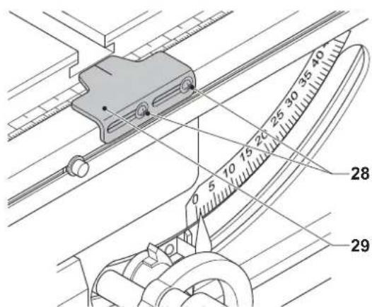
Adjusting the rip scale (fi g. A1 & E)
- Remove the blade guard.
- Unlock the lock lever (12) by pulling it up (fig. A1).
- Unlock the bevel lock lever (11) and set the bevel angle to 0^ .
- Move the fence (7) until it touches the blade.
- Lock the lock lever (12).
- Loosen the rip scale pointer screws (28) and set the pointer (29) to zero (fi g. E).
• Tighten the screws (28)
The rip scale reads correctly only when the fence is mounted to the right of the blade.
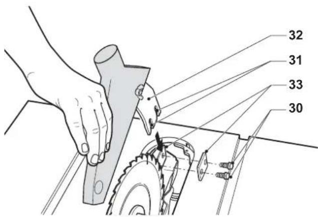
Mounting the riving knife assembly (fi g. A1 & F)
- It is not permitted to mount another riving knife as delivered with this machine.
- The correct position is for the top of the riving knife (32) to be no more than 2 mm below the highest tooth of the blade and the body of the radius to be a maximum of 5 mm from the tips of the saw blade teeth.
- Raise the blade arbor to its maximum by rotating the blade height adjustment wheel (10) clockwise (fi g. A1).
- Slacken the two bolts (30) (fig. F).
- Align the slots (31) with the bolts (30) and insert the fence until the tops of the slots rest on the bolts (fi g. F).
- When properly aligned, the riving knife will be in line with the blade at the table top and at the top of the blade. Check using a straight edge in all bevel and blade height positions.
- If adjustment is required, remove the blade guard and adjust the shims (33).
- Mount the blade guard on the bolts.
• Retighten the bolts (30) securely.

WARNING: Correct mounting and alignment of the riving knife and upper blade guard is essential to safe operation!
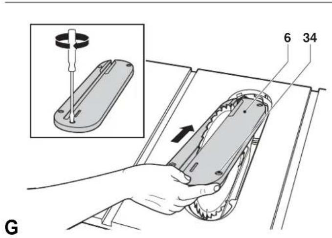
Mounting the table insert (fi g. G)
- Align the table insert (6) as shown and insert the tabs of the back of the table insert into the holes on the back of the table.
- Press down the front of the table insert.
- The front of the table insert must be flush or slightly below the table top. The rear should be flush or slightly above the table top. Adjust using the four adjustment screws (34).
- Turn the locking screw (see insert in fig. G) clockwise 90^ to lock the table insert in place.

WARNING: Never use the machine without the table insert. Immediately replace the table insert when worn or damaged.
Bench mounting (fi g. A1)
- Holes (2) are provided in all four feet to facilitate bench mounting. Two different sized holes are provided to accommodate different sizes of bolts. Use either hole; it is not necessary to use both. Always mount your saw firmly to prevent movement. To enhance the portability, the tool can be mounted to a piece of 12.5 ~mm or thicker plywood which can then be clamped to your work support or moved to other job sites and reclamped.
- When mounting your saw to a piece of plywood, make sure that the mounting screws do not protrude from the bottom of the wood. The plywood must sit fl ush on the work support. When clamping the saw to any work surface, clamp only on the clamping bosses where the mounting screw holes are located. Clamping at any other point will interfere with the proper operation of the saw.
- To prevent binding and inaccuracy, be sure the mounting surface is not warped or otherwise uneven. If the saw rocks on the surface, place a thin piece of material under one saw foot until the saw is firm on the mounting surface.

WARNING: The mounting surface must have a 350 x 500 mm opening to allow dust to escape.
Rail lock adjustment (fi g. A1 & H)
The rail lock has been factory-set. If you need to re-adjust, proceed as follows:
- Lock the lock lever (12) by pushing it down (fig. A1).
- Adjust the nut (35) on the underside of your saw until the gap between the Belleville washers (36) closes (fi g. H).
- Once the Belleville washers are almost touching, loosen the nut (35) half a turn.
Bevel stop and pointer adjustment (fi g. K1 & K2)
- Raise the blade to its maximum by rotating the blade height adjustment wheel (10) clockwise (fig. K1).
- Unlock the bevel lock lever (11) by pushing it up and to the right.
- Loosen the bevel stop screw (37).
- Place a set square (38) on the table and up against the blade (39) (fi g. K2).
- Adjust the bevel angle using the bevel lock lever (11) until the blade is flat at against the square.
• Tighten the bevel lock lever (11). - Turn the bevel stop cam (40) until it firmly contacts the bearing block (fi g. K1).
- Check the bevel angle scale. If adjustment is required, loosen the pointer screw (41) and set the pointer to 0^ .
• Tighten the pointer screw (41). - Repeat the procedure at 45^ for the 45^ bevel stop, but do not adjust the pointer.
Mitre gauge adjustment (fi g. A3 & L)
Your mitre gauge (19) is equipped with adjustable stops at 90° and 45°.
- To adjust these stops, loosen the lock nuts (42) and set the adjusting screws (43) as required.
Adjusting the fence parallel to the blade (fig. B1) (Blade Parallel to Fence)
If you experience fence alignment problems and want to correct an out of parallel between the fence and the blade, be sure to check the alignment of the blade to the miter slot first. After confirming that those elements are aligned, proceed with alignment of the blade to the fence using the following procedure:
- Unlock the rail lock lever (12) and locate the two fence locator screws (20) that support the fence on the front and rear rails.
- Loosen the rear locator screw and adjust the position of the fence in the groove on the fence until it sets the fence face parallel to the blade. Make sure you measure from the fence face to the front and back of the blade to ensure alignment.
- Tighten the locator screw and repeat on the left side of the blade.
- Check rip scale pointer adjustment.
OPERATION
Instructions for use

WARNING:
• Always observe the safety instructions and applicable regulations.
- Ensure the machine is placed to satisfy ergonomic conditions in terms of table height and stability. The machine site shall be chosen so that the operator has a good overview and enough free surrounding space around the machine that allow handling of the workpiece without any restrictions.
• Install the appropriate saw blade. Do not use excessively worn blades. The maximum rotation speed of the tool must not exceed that of the saw blade.
- Do not attempt to cut excessively small pieces.
- Allow the blade to cut freely. Do not force.
- Allow the motor to reach full speed before cutting.
• Make sure all locking knobs and clamp handles are tight.
- Never place either hand in the blade area when the saw is connected to the electrical power source.
• Never use your saw for freehand cuts!
- Do not saw warped, bowed or cupped workpieces. There must be at least one straight, smooth side to go against the rip fence or mitre fence.
• Always support long workpieces to prevent kickback.
- Do not remove any cut-offs from the blade area while the blade is running.
The attention of UK users is drawn to the "woodworking machines regulations 1974" and any subsequent amendments.
Switching on and off (fi g. A1)
The on/off switch of your saw bench offers multiple advantages:
- no-volt release function: should the power be shut off for any reason, the switch has to be deliberately reactivated.
- extra safety: the hinged safety enclosure plate can be locked by passing a padlock through the centre hasp. The plate also serves as an "easy to locate" emergency stop button as pressure on the front of the plate will depress the stop button.
• To switch the machine on, press the green start button.
• To switch the machine off, press the red stop button.
Basic saw cuts
Ripping (fi g. A1, A2, M1 & M2)

WARNING: Sharp edges.
- Set the blade to 0^ .
- Lock the rip fence (7) (fig. A1).
- Raise the blade until it is about 3 mm higher than the top of the workpiece. Adjust the height of the upper blade guard as necessary.
-
Adjust the position of the L-shaped fence profile (16) level with the back of the riving knife. When ripping wide pieces of material, slide the L-shaped fence profile (16) off the main part of the fence, rotate vertically through 180^ and replace to provide additional support.
-
Hold the workpiece flat on the table and against the fence. Keep the workpiece away from the blade.
- Keep both hands away from the path of the blade (fig. M2).
- Switch the machine on and allow the blade to reach full speed.
- Slowly feed the workpiece underneath the guard, keeping it firmly pressed against the rip fence. Allow the teeth to cut, and do not force the workpiece through the blade. The blade speed should be kept constant.
• Always use a push stick (15) when working close to the blade (fig. M1). - After completing the cut, switch the machine off, allow the blade to stop and remove the workpiece.

WARNING:
- Never push or hold the "free" or cut-off-side of the workpiece.
- Do not cut excessively small workpieces.
• Always use a push stick when ripping small workpieces.
Bevel cuts
- Set the required bevel angle (refer to the section "Adjusting the rip scale").
• Proceed as for ripping.
Cross-cutting and bevel crosscutting
- Remove the rip fence and install the mitre gauge in the desired slot.
- Lock the mitre gauge at 0^ .
- Proceed as for ripping.
Mitre cuts (fi g. A1)
- Set the mitre gauge to the required angle.
• Always hold the workpiece tightly against the face of the mitre gauge.
• Proceed as for ripping.
Compound mitre
This cut is a combination of a mitre and a bevel cut.
- Set the bevel to the angle required and proceed as for a cross-cut mitre.
Support for long pieces
• Always support long pieces.
- Support long workpieces using any convenient means such as saw-horses or similar devices to keep the ends from dropping.
Dust extraction (fi g. A2)
The machine is provided with a dust exhaust port at the rear of the machine (14) suitable for use with dust extraction equipment featuring 57/65 mm nozzles. Supplied with the machine is a reducer port for use of dust extraction nozzles of 34-40 mm diameter.
- During all operations, connect a dust extraction device designed in accordance with the relevant regulations regarding dust emission.
- Ensure that the dust extraction hose in use is suitable for the application and material being cut.
- Be aware that man-made materials such as chipboard or MDF produce more dust particles during cutting than natural timber.
Optional accessories

WARNING: Since accessories, other than those offered by DEWALT, have not been tested with this product, use of such accessories with this tool could be hazardous. To reduce the risk of injury, only DEWALT, recommended accessories should be used with this product.
Replace top guard (part no.: 247678-02) when worn.
Consult your dealer for further information on the appropriate accessories.
Transporting (fi g. A1)
• Always carry the machine at the hand indentations (3).

WARNING: Always transport the machine with the upper blade guard fitted.
Maintenance
Your DEWALT machine has been designed to operate over a long period of time with a minimum of maintenance. Continuous satisfactory operation depends upon proper tool care and regular cleaning.

Lubrication (fi g. N)
The motor and bearings require no additional lubrication. If raising and lowering the blade becomes diffi cult, clean and grease the height adjustment screws:
• Turn the saw on its side.
- Clean and grease the height adjustment threads as shown in fig. N. Use general purpose grease.

Cleaning

WARNING: To reduce the risk of serious personal injury, turn unit off and disconnect machine from power source before cleaning. An accidental start-up can cause injury.
To maintain correct operation of your saw, clean the throat plate area regularly. Disassemble throat plate as shown and as described in the instruction manual. Remove saw dust, chips and any other debris. If using compressed air, always wear ANSI Z87.1 approved eye protection.
The guard and throat plate must be placed in position before operating the saw.
Before use, carefully inspect upper and lower blade guards as well as the dust extraction tube to determine that it will operate properly. Ensure that chips, dust or workpiece particles cannot lead to blockage of one of the functions.
In case workpiece fragments are jammed between saw blade and guards, disconnect the machine from the power supply and follow the instructions given in section Mounting the saw blade. Remove the jammed parts and reassemble the saw blade.
Keep the ventilation slots clear and regularly clean the housing with a soft cloth.
• Regularly clean the dust collection system:
• Turn the saw on its side.
- Unfasten the screw (46) (fig. O).
- Remove all dust and resecure the access door (47) using the screw (fi g. O).
Protecting the environment

Separate collection. This product must not be disposed of with normal household waste.
Should you find one day that your DEWALT product needs replacement, or if it is of no further use to you, do not dispose of it with household waste. Make this product available for separate collection.

Separate collection of used products and packaging allows materials to be recycled and used again. Re-use of recycled materials helps prevent environmental pollution and reduces the demand for raw materials.
Local regulations may provide for separate collection of electrical products from the household, at municipal waste sites or by the retailer when you purchase a new product.
DEWALT provides a facility for the collection and recycling of DEWALT products once they have reached the end of their working life. To take advantage of this service please return your product to any authorised repair agent who will collect them on our behalf.
You can check the location of your nearest authorised repair agent by contacting your local DEWALT office at the address indicated in this manual. Alternatively, a list of authorised DEWALT repair agents and full details of our after-sales service and contacts are available on the Internet at: www.2helpU.com
GUARANTEE
DEWALT is confident of the quality of its products and offers an outstanding guarantee for professional users of the product. This guarantee statement is in addition to and in no way prejudices your contractual rights as a professional user or your statutory rights as a private non-professional user. The guarantee is valid within the territories of the Member States of the European Union and the European Free Trade Area.
• 30 DAY NO RISK SATISFACTION GUARANTEE •
If you are not completely satisfied with the performance of your DEWALT tool, simply return it within 30 days, complete with all original components, as purchased, to the point of purchase, for a full refund or exchange. The product must have been subject to fair wear and tear and proof of purchase must be produced.
• ONE YEAR FREE SERVICE CONTRACT •
If you need maintenance or service for your DEWALT tool, in the 12 months following purchase, you are entitled to one service free of charge. It will be undertaken free of charge at an authorised DEWALT repair agent. Proof of purchase must be produced. Includes labour. Excludes accessories and spare parts unless failed under warranty.
• ONE YEAR FULL WARRANTY •
If your DEWALT product becomes defective due to faulty materials or workmanship within 12 months from the date of purchase, DEWALT guarantees to replace all defective parts free of charge or – at our discretion – replace the unit free of charge provided that:
• The product has not been misused;
• The product has been subject to fair wear and tear;
• Repairs have not been attempted by unauthorised persons;
• Proof of purchase is produced;
- The product is returned complete with all original components.
If you wish to make a claim, contact your seller or check the location of your nearest authorised DEWALT repair agent in the DEWALT catalogue or contact your DEWALT office at the address indicated in this manual. A list of authorised DEWALT repair agents and full details of our after-sales service is available on the Internet at: www.2helpU.com.
SIERRA DE MESA DW744/DW744XP
¡Enhorabuena!
L'emballage contient:
Lubrification (fig. N)
Vice President Engineering and Product Development
WAARSCHUWING: Scherpe randen.
11 Retire as chaves de ajuste
Vice President Engineering and Product Development DEWALT, Richard-Klinger-Strasse 11, D-65510, Idstein, Germany
01.08.2009