
EWAD560TZPS - Air Conditioning DAIKIN - Free user manual and instructions
Find the device manual for free EWAD560TZPS DAIKIN in PDF.

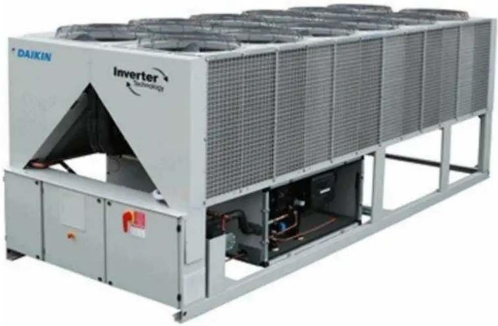
| Product type | Air-cooled chiller with screw compressor |
| Brand | Daikin |
| Model | EWAD560TZPS |
| Refrigerant | R134a (GWP = 1430) |
| Main function | Cooling of water or water-glycol mixture |
| Cooling mode | Air condensation |
| Power supply | Three-phase, voltage as per nameplate; wait 5 minutes after power-off before servicing |
| Frost protection | Electric heater with thermostat down to -25°C; draining or glycol recommended in winter |
| Recommended maintenance | Weekly: data reading; Monthly: visual inspection, flow switch check; Yearly: condenser cleaning, tightening check, oil analysis |
| Condenser coil cleaning | Annual cleaning of condenser banks; more frequent in dusty environments |
| Required water quality | pH 6.8-8.0; hardness <200 mg CaCO3/l; chlorides <200 mg/l; iron <1 mg/l |
| Flow switch | Mandatory on the hydraulic circuit; triggers if flow <50% of rated flow |
| Safety | Ground anchoring; lifting by yellow points; cut power before access; wait 5 min after power-off; use insulating platform; do not obstruct safety valves |
| Pressure classification | Category IV according to directive 2014/68/EU |
| Warranty | 12 months from first start-up or 18 months from delivery |
| Capacitor maintenance | Electrolytic capacitors, lifespan 15 years; replace if warning; reactivation after 1 year shutdown: 30 min powered without starting |
| Outdoor use | Unit designed for outdoor use; avoid air recirculation; respect minimum distances (2.5 m if obstacle same height, 3 m if taller) |
| Heat recovery (option) | Water heat exchanger on compressor discharge; min. water temperature 28°C |
| Spare parts | Filters, capacitors, flow switch, safety valves; contact manufacturer |
| Repairability | Repairs reserved for qualified and authorized personnel |
Frequently Asked Questions - EWAD560TZPS DAIKIN
User questions about EWAD560TZPS DAIKIN
0 question about this device. Answer the ones you know or ask your own.
Ask a new question about this device
Download the instructions for your Air Conditioning in PDF format for free! Find your manual EWAD560TZPS - DAIKIN and take your electronic device back in hand. On this page are published all the documents necessary for the use of your device. EWAD560TZPS by DAIKIN.
USER MANUAL EWAD560TZPS DAIKIN
Installation, Operation and Maintenance Manual Installation, Operation and Maintenance Manual D–EIMAC00908-16EU
Air cooled chiller with inverter driven screw compressor

EWAD\~TZ
Refrigerant: R-134a
natural_image
Exterior view of a large industrial air heater unit (DAIKIN) with Inverter technology branding, no visible text or symbols beyond branding.| English ..... 9 |
| Deutsch .....21 |
| Français .....32 |
| Nederlands.....45 |
| Español .....56 |
| Italiano .....69 |
| Ελληνικά .....80 |
| Português .....93 |
| Русский .....105 |
| Svenska .....117 |
| Norsk .....129 |
| Finnish (Suomi) 141 |
| Polski .....153 |
| Čech .....164 |
| Hrvat .....177 |
| Magyar .....189 |
| Română .....201 |
| Slovensky .....212 |
| Български .....225 |
| Slovenščina.....237 |
A-B
A - Typical refrigerant circuit - Water inlet and outlet are indicative. Please refer to the machine dimensional diagrams for exact water connections.
B - Typical refrigerant circuit with heat recovery - Water inlet and outlet are indicative. Please refer to the machine dimensional diagrams for exact water connections.
A - Typischer Kühlkreislauf – Wasser-Ein- und Ausgang sind unverbindlich. Für die genauen Wasseranschlüsse bitte in den Zeichnungen zur Maschinenbemessung nachsehen.
B - Typischer Kühlkreislauf mit Wärmerückgewinnung – Wasser-Ein- und Ausgang sind unverbindlich. Für die genauen Wasseranschlüsse bitte in den Zeichnungen zur Maschinenbemessung nachsehen.
A - Circuit de réfrigérant standard -Les entrées et sorties d'eau sont indicatives. Consulter les schémas de dimensions de la machine pour avoir des indications plus précises sur les connexions de l'eau.
B - Circuit de réfrigérant standard avec récupération de chaleur -Les entrées et sorties d'eau sont indicatives. Consulter les schémas de dimensions de la machine pour avoir des indications plus précises sur les connexions de l'eau.
A - Typisch koelcircuit - De waterin- en uitlaat zijn indicatief. Raadpleeg de schema's van de machine voor de exacte wateraansluitingen.
B - Typisch koelcircuit met warmteterugwinning - De waterin- en uitlaat zijn indicatief. Raadpleeg de schema's van de machine voor de exacte wateraansluitingen.
A - Circuito de refrigerante típico: las entradas y salidas de agua son indicativas. Por favor, consulte los diagramas de la máquina para conocer las conexiones hidráulica exactas.
B - Circuito de refrigerante típico con un sistema de recuperación de calor: las entradas y salidas de agua son indicativas. Por favor, consulte los diagramas de la máquina para conocer las conexiones hidráulica exactas.
A - Circuito del refrigerante tipico - Gli ingressi e le uscite dell'acqua sono indicativi. Consultare i disegni dimensionali della macchina per indicazioni più precise sulle connessioni dell'acqua.
B - Circuito del refrigerante tipico con recupero di calore - Gli ingressi e le uscite dell'acqua sono indicativi. Consultare i disegni dimensionali della macchina per indicazioni più precise sulle connessioni dell'acqua.
Α - Τυπικό ψυκτικό κύκλωμα - Το νερό εισόδου και εξόδου είναι ενδεικτικά. Ανατρέξτε στα διαγράμματα διαστάσεων του μηχανήματος για τις ακρίβείς συνδέσεις νερού.
B - Τυπικό ψυκτικό κύκλωμα με ανάκτηση θερμότητας - Το νερό εισόδου και εξόδου είναι ενδεικτικά. Ανατρέζτε στα διαγράμματα διαστάσεων του μηχανήματος για τις ακριβείς συνδέσεις νερού.
A - Circuito refrigerante típico - Alimentação e escoamento de água são indicativos. Consultar os desenhos dimensionais da máquina para obter indicações mais exatas sobre as conexões da água.
B - Circuito refrigerante típico com recuperação de calor - Alimentação e escoamento de água são indicativos. Consultar os desenhos dimensionais da máquina para obter indicações mais exatas sobre as conexões da água.
A - типичный контур хладагента - входы и выходы воды указаны ориентировочно. Более подробные указания по подключению воды см. в размерных чертежах машины.
В - типичный контур хладагента с рекуперацией тепла - входы и выходы воды указаны ориентировочно. Более подробные указания по подключению воды см. в размерных чертежах машины.
A - Typisk kylkrets - Vattenintag och uttag är indikativa. Se maskinens dimensionsritningar för exakta vattenanslutningar.
B - Typisk kylkrets med ett system för värmeåtervinning - Vattenintag och uttag är indikativa. Se maskinens dimensionsritningar för exakta vattenanslutningar.
A - typisk kjølekrets – vanninnløp og -utløp er veiledende. Vennligst referer til maskinens måldiagrammer for nøyaktige vannkoblinger.
B - typisk kjølekrets med varmegjenvinning – vanninnlop og -utlop er veiledende. Vennligst referer til maskinens måldiagrammer for nøyaktige vannkoblinger.
This manual is an important supporting document for qualified personnel but it is not intended to replace such personnel.
Thank you for purchasing this chiller

READ THIS MANUAL CAREFULLY BEFORE INSTALLING AND STARTING UP THE UNIT. IMPROPER INSTALLATION COULD RESULT IN ELECTRIC SHOCK, SHORT-CIRCUIT, LEAKS, FIRE OR OTHER DAMAGE TO THE EQUIPMENT OR INJURE TO PEOPLE. THE UNIT MUST BE INSTALLED BY A PROFESSIONAL OPERATOR/TECHNICIAN UNIT STARTUP HAS TO BE PERFORMED BY AUTHORIZED AND TRAINED PROFESSIONAL ALL ACTIVITIES HAVE TO BE PERFORMED ACCORDING TO LOCAL LAWS AND REGULATION. UNIT INSTALLATION AND START UP IS ABOSOLUTELY FORBIDDEN IF ALL INSTRUCTION CONTAINED IN THIS MANUAL ARE NOT CLEAR. IF CASE OF DOUBT CONTACT THE MANUFACTURER REPRESENTATIVE FOR ADVICE AND INFORMATION.
Description
The unit you bought is an "air cooled chiller", a machine aimed to cool water (or water-glycol mixture) within the limits described in the following. The unit operation is based on vapour compression, condensation and evaporation according to reverse Carnot cycle. The main components are:
- Screw compressor to rise the refrigerant vapour pressure from evaporation pressure to condensation pressure
- Evaporator, where the low pressure liquid refrigerant evaporates to cool the water
- Condenser, where high pressure vapour condensate rejecting heat removed from the chilled water in the atmosphere thanks to an air cooled heat exchanger.
- Expansion valve allowing to reduced the pressure of condensed liquid from condensation pressure to evaporation pressure.
General Information

All units are delivered with wiring diagrams, certified drawings, nameplate; and DOC (Declaration Of Conformity); these documents show all technical data for the unit you have bought and they MUST BE CONSIDERED ESSENTIAL DOCUMENTS OF THIS MANUAL
In case of any discrepancy between this manual and the equipment's documents please refer to on board documents. In case of any doubt contact the manufacturer representative.
The purpose of this manual is to allow the installer and the qualified operator to ensure proper installation, commissioning and maintenance of the unit, without any risk to people, animals and/or objects.
Receiving the unit
The unit must be inspected for any possible damage immediately upon reaching final place of installation. All components described in the delivery note must be inspected and checked.
Should the unit be damaged, do not remove the damaged material and immediately report the damage to the transportation company and request they inspect the unit.. Immediately report the damage to the manufacturer representative, a set of photographs are helpful in recognizing responsibility
Damage must not be repaired before the inspection of the transportation company representative.
Before installing the unit, check that the model and power supply voltage shown on the nameplate are correct. Responsibility for any damage after acceptance of the unit cannot be attributed to the manufacturer.
Operating limits
Storing
Environmental conditions must be within the following limits:
Minimum ambient temperature : -20^
Maximum ambient temperature : 57°C
Maximum R.H. : 95% not condensing
Storing below the minimum temperature may cause damage to components. Storing above the maximum temperature causes opening of safety valves. Storing in condensing atmosphere may damage electronic components.
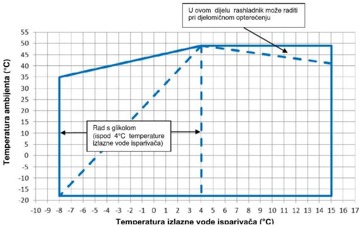
Operation
Operation is allowed within the limits mentioned in the following figures "Operating limits".
The unit must be operated with an evaporator water flow rate between 50% and 140% of nominal flow rate (at standard operating conditions).
Operation out of the mentioned limits may damage the unit.
In case of doubts contact manufacturer representative.
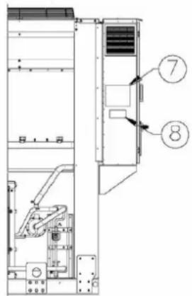
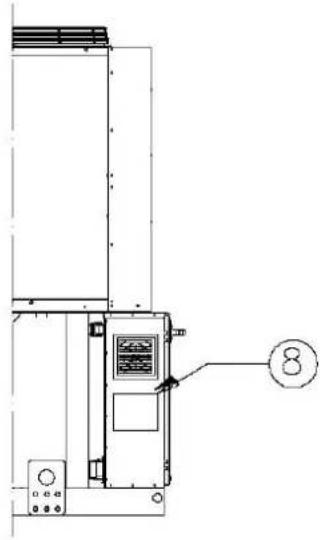
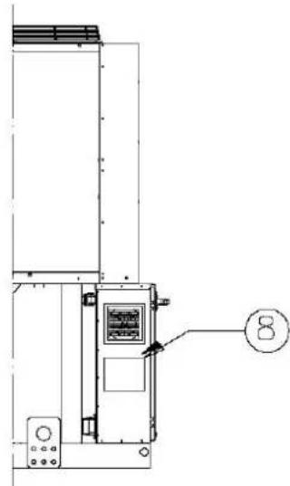
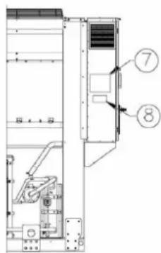
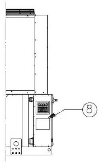
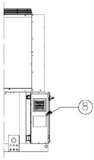
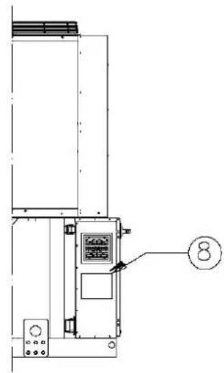
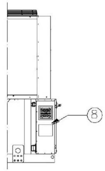
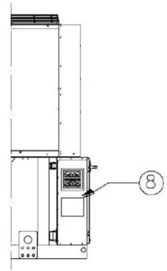
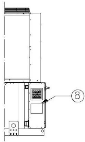
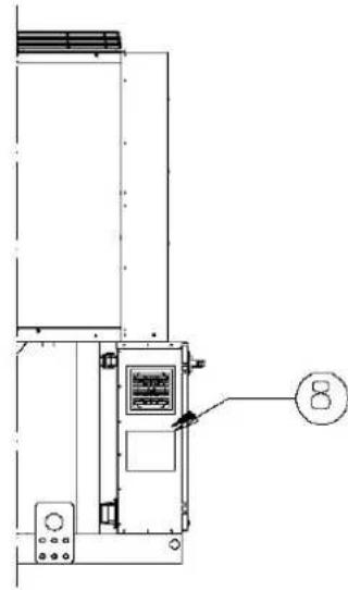
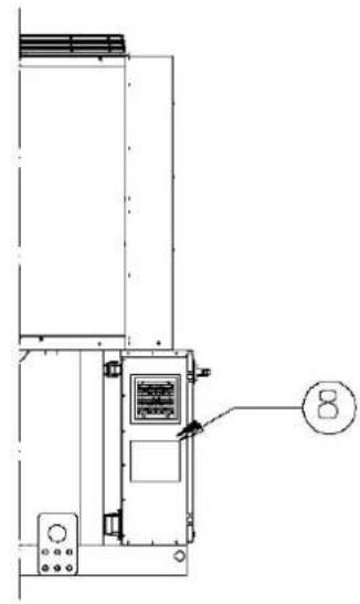
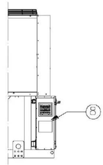
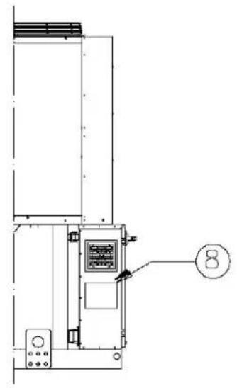
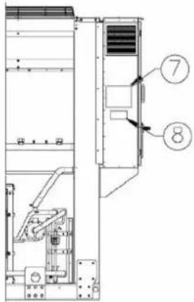
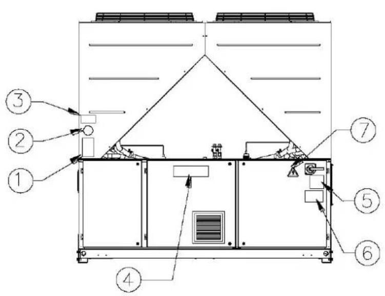
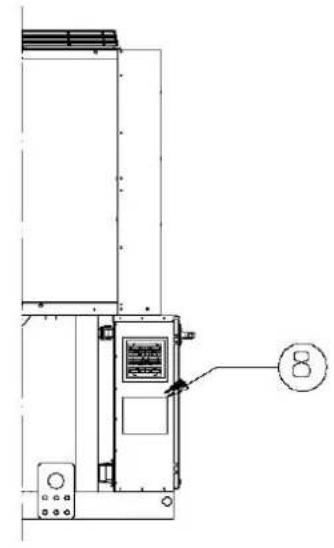
Figure 1 - Description of the labels applied to the electrical panel
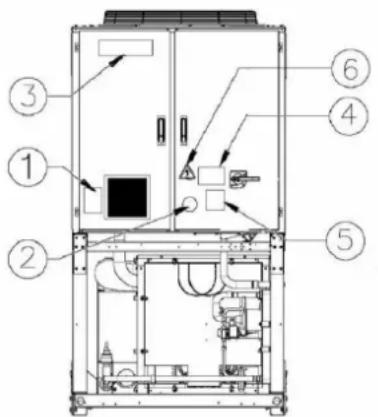
Label Identification
| 1 – Non flammable gas symbol | 5 – Cable tightening warning |
| 2 – Gas type | 6 – Electrical hazard symbol |
| 3 – Manufacturer's logo | 7 – Lifting instructions |
| 4 – Hazardous Voltage warning | 8 – Unit nameplate data |

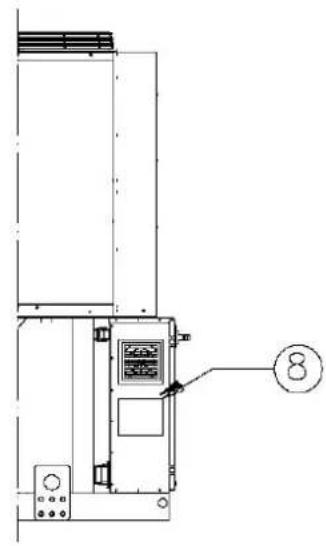
Label identification
| 1 – Non flammable gas symbol | 5 – Cable tightening warning |
| 2 – Gas type | 6 – Hazardous Voltage warning |
| 3 – Unit nameplate data | 7 – Electrical hazard symbol |
| 4 – Manufacturer's logo | 8 – Lifting instructions |
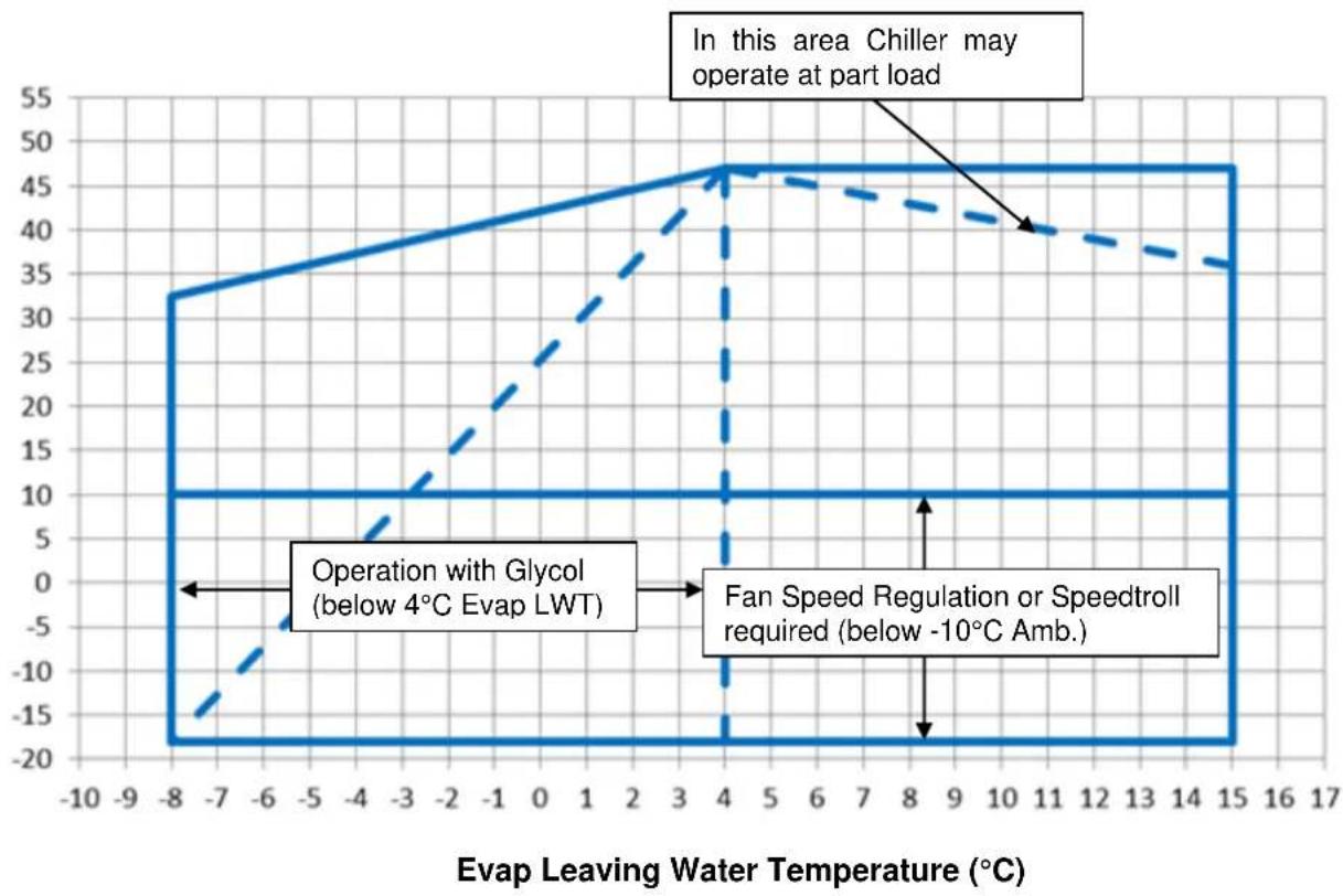
Figure 2 - Operating limits – Standard Efficiency
line
| Evap Leaving Water Temperature (°C) | In this area Chiller may operate at part load | Operation with Glycol (below 4°C Evap LWT) | Fan Speed Regulation or Speedtroll required (below -10°C Amb.) | | ----------------------------------- | --------------------------------------------- | ------------------------------------------ | --------------------------------------------------------------- | | -8 | 32 | -15 | -15 | | -7 | 34 | -10 | -10 | | -6 | 36 | -5 | -5 | | -5 | 38 | 0 | 0 | | -4 | 40 | 5 | 5 | | -3 | 42 | 10 | 10 | | -2 | 44 | 15 | 15 | | -1 | 46 | 20 | 20 | | 0 | 48 | 25 | 25 | | 1 | 49 | 30 | 30 | | 2 | 49.5 | 35 | 35 | | 3 | 49.8 | 40 | 40 | | 4 | 49.9 | 45 | 45 | | 5 | 49.9 | 45 | 45 | | 6 | 49.9 | 45 | 45 | | 7 | 49.9 | 45 | 45 | | 8 | 49.9 | 45 | 45 | | 9 | 49.9 | 45 | 45 | | 10 | 49.9 | 45 | 45 | | 11 | 49.9 | 45 | 45 | | 12 | 49.9 | 45 | 45 | | 13 | 49.9 | 45 | 45 | | 14 | 49.9 | 45 | 45 | | 15 | 49.9 | 45 | 45 | | 16 | 49.9 | 45 | 45 | | 17 | 49.9 | 45 | 45 |Figure 3 - Operating limits – High Efficiency
line
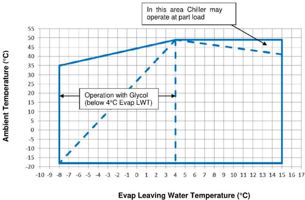
| Evap Leaving Water Temperature (°C) | Ambient Temperature (°C) | | ----------------------------------- | ------------------------ | | -8 | 35 | | 4 | 50 | | 15 | 50 |Figure 4 - Operating limits – Premium Efficiency
line
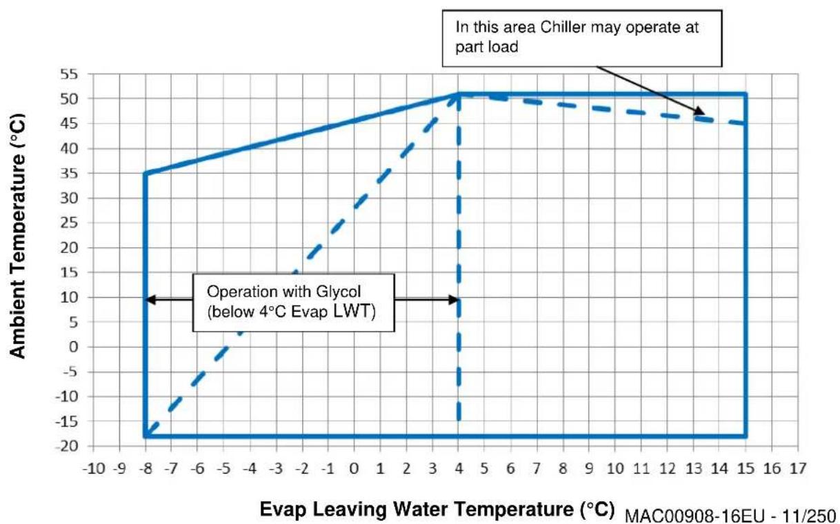
| Evap Leaving Water Temperature (°C) | Ambient Temperature (°C) | | ----------------------------------- | ------------------------ | | -8 | 35 | | 4 | 50 | | 15 | 50 |Safety
The unit must be firmly secured to the soil.
It is essential to observe the following instructions:
- The unit can only be lifted using the lifting points marked in yellow fixed to its base.
- It is forbidden to access the electrical components without having opened the unit main switch and switched off the power supply.
- It is forbidden to access the electrical components without using an insulating platform. Do not access the electrical components if water and/or moisture are present.
- Sharp edges and the surface of the condenser section could cause injury. Avoid direct contact and use adequate protection device
- Switch off power supply, by opening the main switch, before servicing the cooling fans and/or compressors. Failure to observe this rule could result in serious personal injury.
- Do not introduce solid objects into the water pipes while the unit is connected to the system.
- A mechanical filter must be installed on the water pipe connected to the heat exchanger inlet.
- The unit is supplied with safety valves, that are installed both on the high-pressure and on the low-pressure sides of the refrigerant circuit.
It is absolutely forbidden to remove all protections of moving parts.
In case of sudden stop of the unit, follow the instructions on the Control Panel Operating Manual which is part of the onboard documentation delivered to the end user.
It is strongly recommended to perform installation and maintenance with other people. In case of accidental injury or unease, it is necessary to:
keep calm
- press the alarm button if present in the installation site
- move the injured person in a warm place far from the unit and in rest position
- contact immediately emergency rescue personnel of the building or the Health Emergency Service
- wait without leaving the injured person alone until the rescue operators come
- give all necessary information to the rescue operators

Avoid installing the chiller in areas that could be dangerous during maintenance operations, such as platforms without parapets or railings or areas not complying with the clearance requirements around the chiller.
Noise
The unit is a source of noise mainly due to rotation of compressors and fans.
The noise level for each model size is listed in sales documentation.
If the unit is correctly installed, operated and manteined the noise emission level do not require any special protection device to operate continuously close to the unit without any risk. In case of installation with special noise requirements it could be necessary to install additional sound attenuation devices.
Moving and lifting
Avoid bumping and/or jolting during loading/unloading unit from the truck and moving it. Do not push or pull the unit from any part other than the base frame. Secure the unit inside the truck to prevent it from moving and causing damages. Do not allow any part of the unit to fall during transportation or loading/unloading.
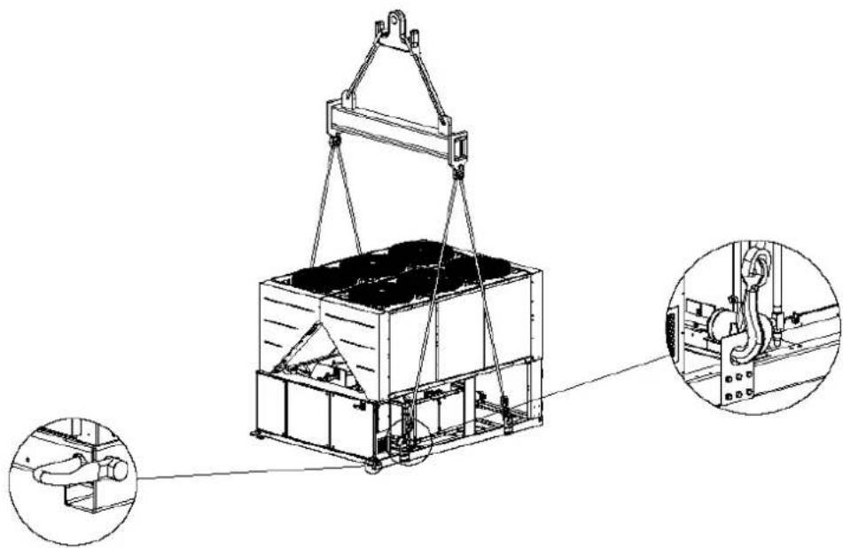
All units of the series are supplied with lifting points marked in yellow. Only these points may be used for lifting the unit, as shown in the following figure.
Use spacing bars to prevent damage to the condensation bank. Position these above the fan grills at a distance of at least 2.5 metres.

Both the lifting ropes and the spacing bars must be strong enough to support the unit safely. Please check the unit's weight on the unit nameplate.
The unit must be lifted with the utmost attention and care following lifting label instructions; lift unit very slowly, keeping it perfectly level.
Positioning and assembly
All units are designed for installation outdoors, either on balconies or on the ground, provided that the installation area is free of obstacles that could reduce air flow to the condensers coil.
The unit must be installed on a robust and perfectly level foundation; should the unit be installed on balconies or roofs, it might be necessary to use weight distribution beams.
Figure 5 - Lifting the unit
1 Compressor unit – "V" shape coils
4-5 fans version

natural_image
Technical line drawing of a mechanical device suspended by crane, with two inset views showing internal components (no text or symbols)6 - 14 fans version
(The drawing shows only the 6 fans version. For the 6-8-10-12-14 fans version the lifting mode is the same)
natural_image
Technical line drawing of a crane lifting a container, with two inset views showing mechanical components (no text or symbols)For installation on the ground, a strong concrete base, at least 250 mm thickness and wider than the unit must be provided.
This base must be able to support the weight of the unit.
If the unit is installed in places that are easily accessible to people and animals, it is advisable to install protection grids for the condenser and compressor sections.
To ensure best performance on the installation site, the following precautions and instructions must be followed:
- Avoid air flow recirculation.
- Make sure that there are no obstacles to hamper air flow.
- Make sure to provide a strong and solid foundation to reduce noise and vibrations.
- Avoid installation in particularly dusty environments, in order to reduce soiling of condensers coils.
- The water in the system must be particularly clean and all traces of oil and rust must be removed. A mechanical water filter must be installed on the unit's inlet piping.
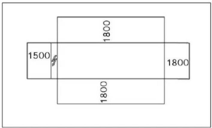
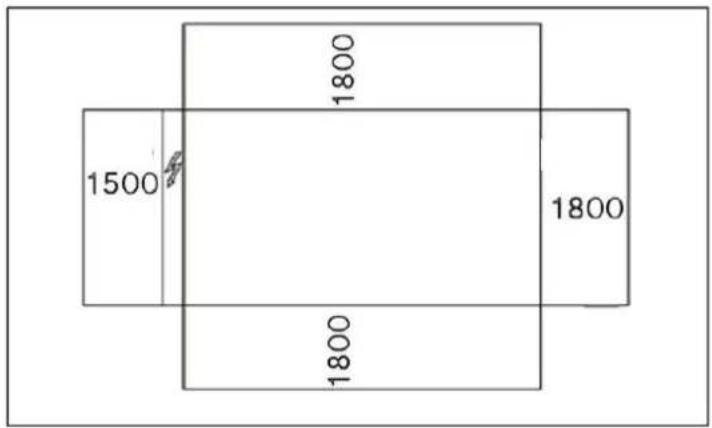
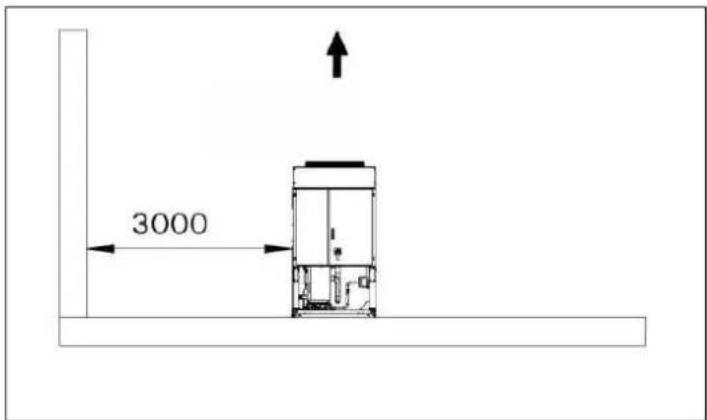
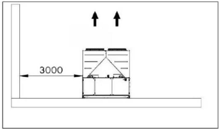
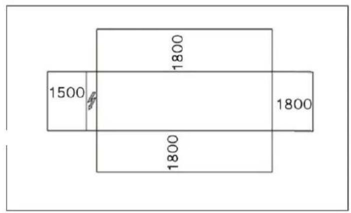
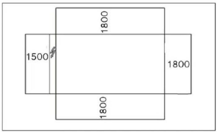
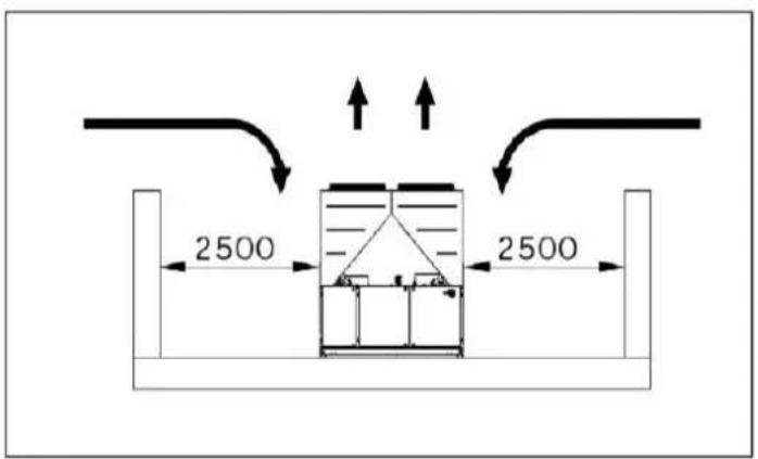
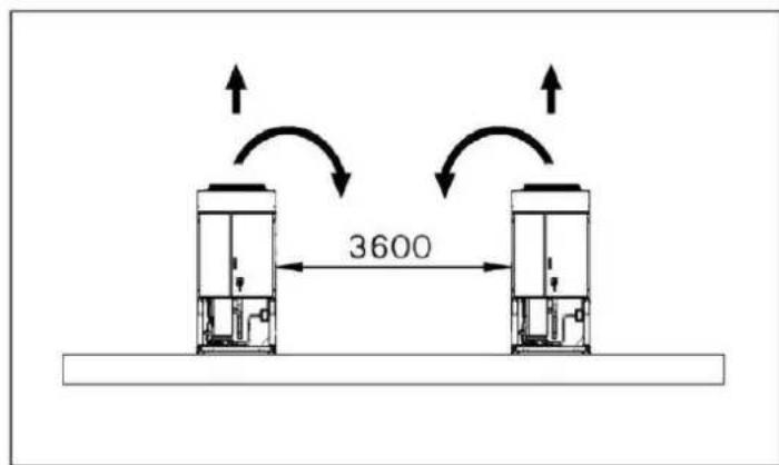
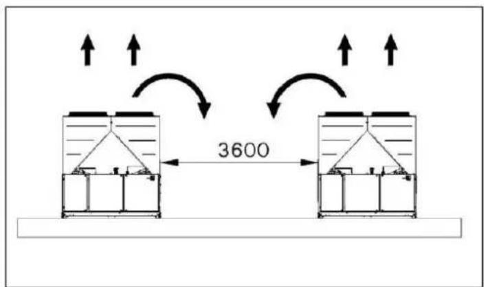
Minimum space requirements
It is fundamental to respect minimum distances on all units in order to ensure optimum ventilation to the condenser coils.
When deciding where to position the unit and to ensure a proper air flow, the following factors must be taken into consideration:
- avoid any warm air recirculation
- avoid insufficient air supply to the air-cooled condenser.
Both these conditions can cause an increase of condensing pressure, which leads to a reduction in energy efficiency and refrigerating capacity.
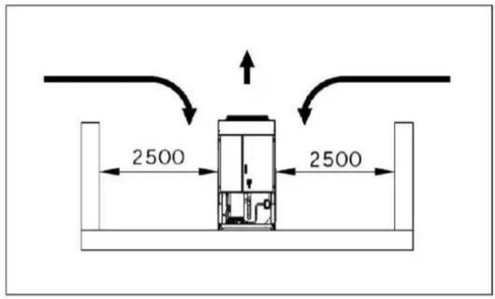
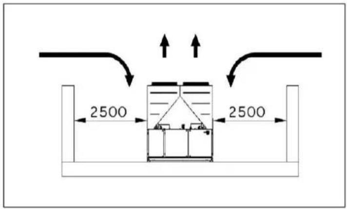
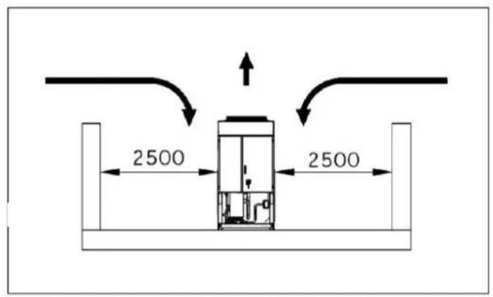
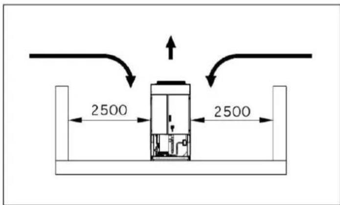
Any side of the unit must be accessible for post-installation maintenance operations. Figure 3 shows the minimum space required.
Vertical air discharge must not be obstructed.
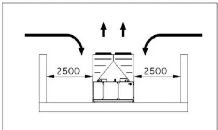
If the unit is surrounded by walls or obstacles of the same height as the unit, this must be installed at a distance no lower than 2500 mm.
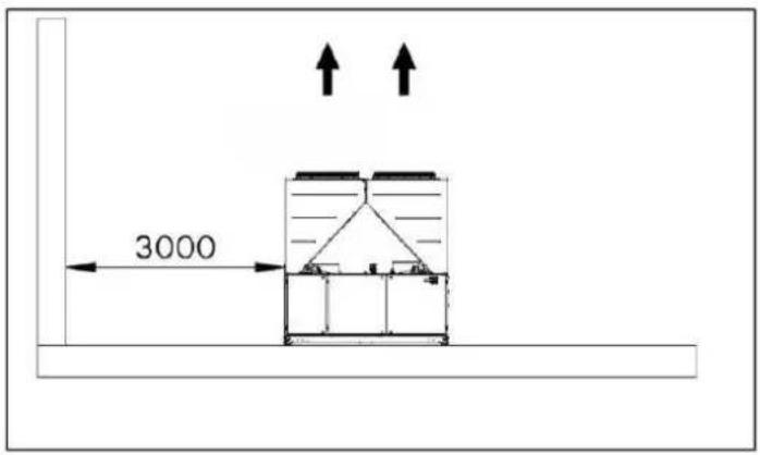
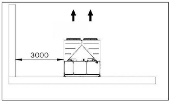
If these obstacles are higher, the unit must be installed at a distance no lower than 3000 mm.
Should the unit be installed without observing the recommended minimum distances from walls and/or vertical obstacles, there could be a combination of warm air
recirculation and/or insufficient supply to the air-cooled condenser which could cause a reduction of capacity and efficiency.
In any case, the microprocessor will allow the unit to adapt itself to new operating conditions and deliver the maximum available capacity under any given circumstances, even if the lateral distance is lower than recommended, unless the operating conditions should affect personnel safety or unit reliability.
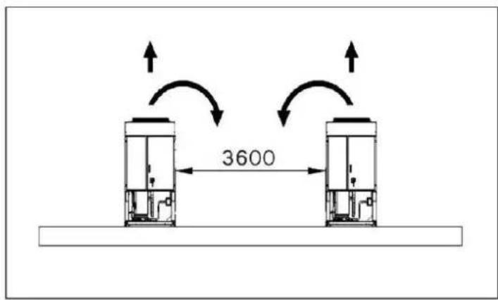
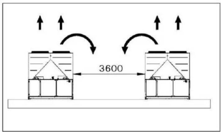
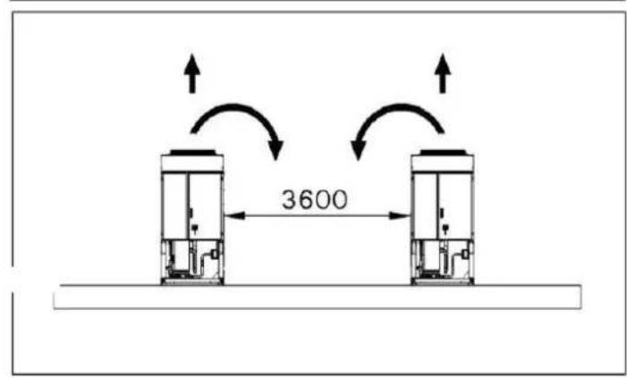
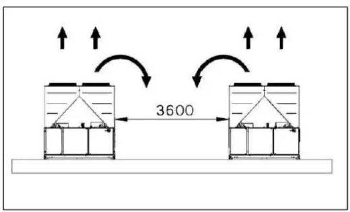
When two or more units are positioned side by side, a distance of at least 3600 mm between condenser banks is recommended.
For further solutions, please consult manufacturer representative.
Sound protection
When sound levels require special control, great care must be exercised to isolate the unit from its base by appropriately applying anti-vibration elements (supplied as an option). Flexible joints must be installed on the water connections, as well.
Water piping
Piping must be designed with the lowest number of elbows and the lowest number of vertical changes of direction. In this way, installation costs are reduced considerably and system performance is improved.
The water system must have:
- Anti-vibration mountings in order to reduce transmission of vibrations to the structures.
- Isolating valves to isolate the unit from the water system during maintenance.
- Flow switch.
- Manual or automatic air venting device at the system's highest point.; drain device at the system's lowest point.
- Neither the evaporator nor the heat recovery device must be positioned at the system's highest point.
- A suitable device that can maintain the water system under pressure (expansion tank, etc.).
- Water temperature and pressure indicators to assist the operator during service and maintenance.
Figure 6 – Minimum clearance requirements
- A filter or device that can remove particles from the fluid. The use of a filter extends the life of the evaporator and pump and helps to keep the water system in a better condition.
- Evaporator has an electrical resistance with a thermostat that ensures protection against water freezing at ambient temperatures as low as -25^ .
All the other water piping/devices outside the unit must therefore be protected against freezing. - The heat recovery device must be emptied of water during the winter season, unless an ethylene glycol mixture in appropriate percentage is added to the water circuit.
- If case of unit substitution, the entire water system must be emptied and cleaned before the new unit is installed. Regular tests and proper chemical treatment of water are recommended before starting up the new unit.
- In the event that glycol is added to the water system as anti-freeze protection, pay attention to the fact that suction pressure will be lower, the unit's performance will be lower and water pressure drops will be greater. All unit-protection systems, such as anti-freeze, and low-pressure protection will need to be readjusted.
- Before insulating water piping, check that there are no leaks.
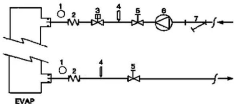
Figure 7 - Water piping connection for evaporator
flowchart
graph TD
    A["Component 1"] --> B["Component 2"]
    B --> C["Component 3"]
    C --> D["Component 4"]
    D --> E["Component 5"]
    E --> F["Component 6"]
    F --> G["Component 7"]
    G --> H["Output"]
    I["Component 1"] --> J["Component 2"]
    J --> K["Component 3"]
    K --> L["Component 4"]
    L --> M["Component 5"]
    M --> N["Component 6"]
    N --> O["Output"]
- Pressure Gauge
- Flexible connector
- Flow switch
- Temperature probe
- Isolation Valve
- Pump
- Filter
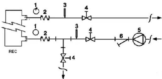
Figure 8 - Water piping connection for heat recovery exchangers
flowchart
graph TD
    REC --> 1
    REC --> 2
    1 --> 3
    2 --> 3
    3 --> 4
    4 --> f
    5 --> f'
    6 --> f
    4 --> 4
    4 --> 3
    3 --> 4
    4 --> 3
    3 --> 2
    2 --> 1
    1 --> 1
    4 --> 4
    4 --> 5
- Pressure Gauge
- Flexible connector
- Temperature probe
- Isolation Valve
- Pump
- Filter
Water treatment
Before putting the unit into operation, clean the water circuit. Dirt, scales, corrosion debris and other material can accumulate inside the heat exchanger and reduce its heat exchanging capacity. Pressure drop can increase as well, thus reducing water flow. Proper water treatment therefore reduces
the risk of corrosion, erosion, scaling, etc.. The most appropriate water treatment must be determined locally, according to the type of system and water characteristics. The manufacturer is not responsible for damage to or malfunctioning of equipment caused by failure to treat water or by improperly treated water.
Table 1 - Acceptable water quality limits
| pH (25°C) | 6,8÷8,0 | Total Hardness (mg CaCO_3 /l) | < 200 | |
| Electrical conductivity μS/cm (25°C) | <800 | Iron (mg Fe / l) | < 1.0 | |
| Chloride ion (mg Cl^- /l) | <200 | Sulphide ion (mg S^2- /l) | None | |
| Sulphate ion (mg SO_4^2 /l) | <200 | Ammonium ion (mg NH_4^+ /l) | < 1.0 | |
| Alkalinity (mg CaCO_3 /l) | <100 | Silica (mg SiO_2 /l) | < 50 |
Evaporator and recovery exchangers anti-freeze protection
All evaporators are supplied with a thermostatically controlled anti-freeze electrical resistance, which provides adequate anti-freeze protection at temperatures as low as -25^ .
However, unless the heat exchangers are completely empty and cleaned with anti-freeze solution, additional methods should also be used against freezing.
Two or more of below protection methods should be considered when designing the system as a whole:
Continuous water flow circulation inside piping and exchangers
– Addition of an appropriate amount of glycol inside the water circuit
– Additional heat insulation and heating of exposed piping
– Emptying and cleaning of the heat exchanger during the winter season
It is the responsibility of the installer and/or of local maintenance personnel to ensure that described anti-freeze methods are used. Make sure that appropriate anti-freeze protection is maintained at all times. Failing to follow the instructions above could result in unit damage. Damage caused by freezing is not covered by the warranty.
Installing the flow switch
To ensure sufficient water flow through the evaporator, it is essential that a flow switch be installed on the water circuit.
The flow switch can be installed either on the inlet or outlet water piping. The purpose of the flow switch is to stop the unit in the event of interrupted water flow, thus protecting the evaporator from freezing.
The manufacturer offers, as optional, a flow switch that has been selected for this purpose.
This paddle-type flow switch is suitable for heavy-duty outdoor applications (IP67) and pipe diameters in the range of 1" to 6". The flow switch is provided with a clean contact which must be electrically connected to terminals shown in the wiring diagram.
Flow switch has to be tune to intervene when the evaporator water flow is lower than 50% of nominal flow rate.
Heat recovery
Units may be optionally equipped with heat recovery system. This system in made by a water cooled heat exchanger located on the compressors discharge pipe and a dedicated management of condensing pressure.
To guarantee compressor operation within its envelope, units with heat recovery cannot operate with water temperature of the heat recovery water lower than 28^ C.
It is a responsibility of plant designer and chiller installer to guarantee the respect of this value (e.g. using recirculating bypass valve)
Electrical Installation
General specifications

All electrical connections to the unit must be carried out in compliance with laws and regulations in force.
All installation, management and maintenance activities must be carried out by qualified personnel. Refer to the specific wiring diagram for the unit you have bought. Should the wiring diagram not be on the unit or should it have been lost, please contact your manufacturer representative, who will send you a copy. In case of discrepancy between wiring diagram and electrical panel/cables, please contact the manufacturer representative.
Only use copper conductors. Failure to use copper conductors could result in overheating or corrosion at connection points and could damage the unit.
To avoid interference, all control wires must be connected separately from the power cables. Use different electrical passage ducts for this purpose.
Particular care must be taken when realizing wire connections to the switchbox; if not properly sealed, cable entries may allow ingress of water into the switchbox which may cause damage to the equipment inside.

Before any installation and connection works, the unit must be switched off and secured. Since this unit includes inverters, the intermediate circuit of the capacitors remains charged with high voltage for a short period of time after being switched off. Do not operate to the unit before 5 minutes after the unit has been switched off.
This unit includes non-linear loads such as inverters, which have a natural current leakage to earth. If an Earth Leakage Detector is installed upstream the unit, a type B device with a minimum threshold of 300 mA must be used.
This product complies with EMC standards for industrial environments. Therefore it is not intended for use in residential areas, e.g. installations where the product is connected to a low voltage public distribution system. Should this product need to be connected to a low voltage public distribution system, specific additional measures will have to be taken to avoid interference with other sensitive equipment.
Operation
Operator's responsibilities
It is essential that the operator is appropriately trained and becomes familiar with the system before operating the unit. In addition to reading this manual, the operator must study the microprocessor operating manual and the wiring diagram in order to understand start-up sequence, operation, shutdown sequence and operation of all the safety devices.
During the unit's initial start-up phase, a technician authorized by the manufacturer is available to answer any questions and to give instructions as to the correct operating procedures.
The operator must keep a record of operating data for every installed unit. Another record should also be kept of all the periodical maintenance and servicing activities.
If the operator notes abnormal or unusual operating conditions, he is advised to consult the technical service authorized by the manufacturer.
Routine maintenance
Minimum maintenance activities are listed in table 2.
Inverter Electrolytic Capacitors
Compressor Inverters include electrolytic capacitors which have been designed to last a minimum of 15 years in normal use. Heavy duty conditions may reduce the actual life of capacitors.
The chiller calculates capacitor residual life based on actual operation. When residual life gets below a give threshold, a warning is issued by the controller. In this case replacement of capacitors is recommended. This operation must be done only by qualified technicians. Replacement must be carried out through the following procedure:
• Power off the chiller
• Wait for 5 minutes before opening the inverter case
• Check that residual dc voltage in the dc link is zero.
- Open the inverter case and replace old capacitors with new ones.
- Reset the chiller controller through the maintenance menu. This will allow the controller to recalculate the new estimated life of the capacitors.
Capacitor Reforming after long shut-off period
Electrolytic capacitors may lose part of their original characteristics if they are not powered for more than 1 year. If chiller has been shut off for a longer period a “reforming” procedure as follows is necessary:
• Power on the inverter
- Keep it powered on without starting the compressor for at least 30 minutes
• After 30 minutes the compressor can be started
Low Ambient Start-up
Inverters include a temperature control which allows them to withstand ambient temperatures down to -20^ . However they should not be switched on at temperatures lower than 0^ unless the following procedure is executed:
- Open the switchbox (only trained technicians should perform this operation)
- Open compressor fuses (by pulling the fuse holders) or compressor circuit breakers
• Power on the chiller - Keep the chiller powered on for 1 hour at least (this allows inverter heaters to warm-up the inverter).
- Close fuse holders
- Close the switchbox
Service and limited warranty
All units are factory-tested and guaranteed for 12 months as of the first start-up or 18 months as of delivery.
These units have been developed and constructed according to high quality standards ensuring years of failure-free operation. It is important, however, to ensure proper and periodical maintenance in accordance with all the procedures listed in this manual and with good practice of machines maintenance.
We strongly advise stipulating a maintenance contract with a service authorized by the manufacturer in order to ensure efficient and problem-free service, thanks to the expertise and experience of our personnel.
It must also be taken into consideration that the unit requires maintenance also during the warranty period.
It must be borne in mind that operating the unit in an inappropriate manner, beyond its operating limits or not
performing proper maintenance according to this manual can void the warranty.
Observe the following points in particular, in order to conform to warranty limits:
- The unit cannot function beyond the specified limits
- The electrical power supply must be within the voltage limits and without voltage harmonics or sudden changes.
- The three-phase power supply must not have un balance between phases exceeding 3%. The unit must stay turned off until the electrical problem has been solved.
- No safety device, either mechanical, electrical or electronic must be disabled or overridden.
- The water used for filling the water circuit must be clean and suitably treated. A mechanical filter must be installed at the point closest to the evaporator inlet.
- Unless there is a specific agreement at the time of ordering, the evaporator water flow rate must never be above 120% and below 80% of the nominal flow rate.
Periodic obligatory checks and starting up of appliances under pressure
The units are included in category IV of the classification established by the European Directive PED 2014/68/EU.
For chillers belonging to this category, some local regulations require a periodic inspection by an authorized agency. Please check with your local requirements.
Table 2 - Routine maintenance programme
| List of Activities | Weekly | Monthly (Note 1) | Yearly/Seas Onal (Note 2) |
| General: | |||
| Reading of operating data (Note 3) | X | ||
| Visual inspection of unit for any damage and/or loosening | X | ||
| Verification of thermal insulation integrity | X | ||
| Clean and paint where necessary | X | ||
| Analysis of water (6) | X | ||
| Check of flow switch operation | X | ||
| Electrical: | |||
| Verification of control sequence | X | ||
| Verify contactor wear – Replace if necessary | X | ||
| Verify that all electrical terminals are tight – Tighten if necessary | X | ||
| Clean inside the electrical control board | X | ||
| Visual inspection of components for any signs of overheating | X | ||
| Verify operation of compressor and oil heater | X | ||
| Measure compressor motor insulation using the Megger | X | ||
| Clean air intake filters of the electrical panel | X | ||
| Verify operation of all ventilation fans in the electrical panel | X | ||
| Verify operation of inverter cooling valve and heater | X | ||
| Verify status of capacitors in the inverter (signs of damage, leaks, etc) | X | ||
| Refrigeration circuit: | |||
| Check for any refrigerant leakage | X | ||
| Verify refrigerant flow using the liquid sight glass – Sight glass full | X | ||
| Verify filter dryer pressure drop | X | ||
| Verify oil filter pressure drop (Note 5) | X | ||
| Analyse compressor vibrations | X | ||
| Analyse compressor oil acidity (7) | X | ||
| Condenser section: | |||
| Clean condenser banks (Note 4) | X | ||
| Verify that fans are well tightened | X | ||
| Verify condenser bank fins – Comb if necessary | X |
Notes:
1. Monthly activities include all the weekly ones.
2. The annual (or early season) activities include all weekly and monthly activities.
3. Unit operating values should be read on a daily basis thus keeping high observation standards.
4. In environments with a high concentration of air-borne particles, it might be necessary to clean the condenser bank more often.
5. Replace the oil filter when the pressure drop across it reaches 2.0 bar.
6. Check for any dissolved metals.
7. TAN (Total Acid Number) :
≤0.10 : No action
Between 0.10 and 0.19 : Replace anti-acid filters and re-check after 1000 running hours. Continue to replace filters until the TAN is lower than 0.10.
0,19 : Replace oil, oil filter and filter dryer. Verify at regular intervals.
Important information regarding the refrigerant used
This product contains fluorinated greenhouse gasesl. Do not vent gases into the atmosphere.
Refrigerant type: R134a
GWP(1) value: 1430
(1)GWP = Global Warming Potential
The refrigerant quantity necessary for standard operation is indicated on the unit name plate.
Real refrigerant quantity charged in the unit is listed on a silver sticker inside the electrical panel.
Periodical inspections for refrigerant leaks may be required depending on European or local legislation.
Factory and Field charged units instructions
(Important information regarding the refrigerant used)
The refrigerant system will be charged with fluorinated greenhouse gases.
Do not vent gases into the atmosphere.
1 Fill in with indelible ink the refrigerant charge label supplied with the product as following instructions:
- the refrigerant charge for each circuit (1; 2; 3)
- the total refrigerant charge (1 + 2 + 3)
- calculate the greenhouse gas emission with the following formula:
GWP value of the refrigerant x Total refrigerant charge (in kg) / 1000
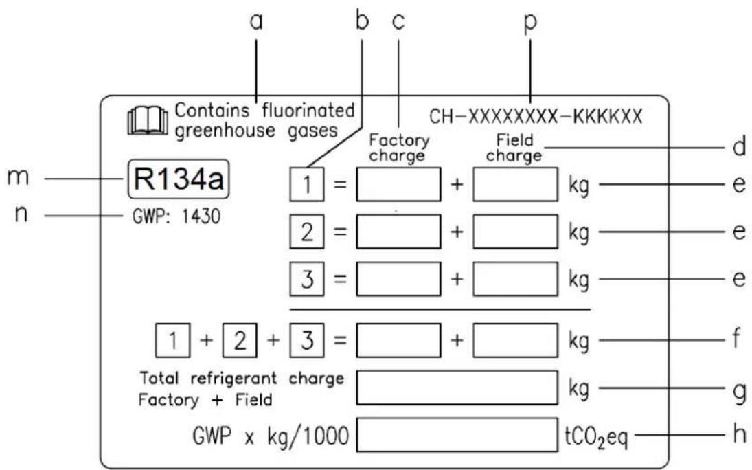
a Contains fluorinated greenhouse gases
b Circuit number
c Factory charge
d Field charge
e Refrigerant charge for each circuit (according to the number of circuits)
f Total refrigerant charge
g Total refrigerant charge (Factory + Field)
h Greenhouse gas emission of the total refrigerant charge expressed as tonnes of CO2 equivalent
m Refrigerant type
n GWP = Global Warming Potential
p Unit serial number
2 The filled out label must be adhered inside the electrical panel.
Periodical inspections for refrigerant leaks may be required depending on European or local legislation. Please contact your local dealer for more information.

NOTICE
D-EIMAC00908-16EU - 19/250
In Europe, the greenhouse gas emission of the total refrigerant charge in the system (expressed as tonnes CO_2 equivalent) is used to determine the maintenance intervals. Follow the applicable legislation.
Formula to calculate the greenhouse gas emission:
GWP value of the refrigerant x Total refrigerant charge (in kg) / 1000
Use the GWP value mentioned on the greenhouse gases label. This GWP value is
based on the 4th IPCC Assessment Report. The GWP value mentioned in the manual might be outdated (i.e. based on the 3rd IPCC Assessment Report)
Please contact your local dealer for more information.
Disposal
The unit is made of metal, plastic and electronic parts. All these parts must be disposed of in accordance with the local regulations in terms of disposal.
Lead batteries must be collected and sent to specific refuse collection centres.
Oil must be collected and sent to specific refuse collection centres.
This manual is a technical aid and does not represent a binding offer. The content cannot be held as explicitly or implicitly guaranteed as complete, precise or reliable. All data and specifications contained herein may be modified without notice. The data communicated at the moment of the order shall hold firm.
The manufacturer shall assume no liability whatsoever for any direct or indirect damage, in the widest sense of the term, ensuing from or connected with the use and/or interpretation of this manual.
We reserve the right to make changes in design and construction at any time without notice, thus the cover picture is not binding.

natural_image
Technical line drawing of a mechanical device suspended by crane, with two inset views showing internal components (no text or symbols)natural_image
Technical line drawing of a mechanical lifting device with two inset views showing internal components (no text or symbols)D-EIMAC00908-16EU - 25/250
n GWP = Global warming potential (Treibhauspotential)

natural_image
Technical line drawing of a mechanical device suspended by crane, with two inset views showing internal components (no text or symbols)natural_image
Technical line drawing of a crane lifting a rectangular component, with two circular insets showing close-ups of mechanical components (no text or symbols present)Figure 6 – Espaces techniques minimum


natural_image
Technical line drawing of an electrical enclosure with a circular component labeled '8' pointing to its interior (no text or symbols beyond the label)natural_image
Technical line drawing of a mechanical device suspended by crane, with two circular insets showing close-ups of internal components (no text or symbols)natural_image
Technical line drawing of a mechanical lifting device with two inset views showing internal components (no text or symbols)

natural_image
Technical line drawing of an electrical enclosure or control unit with labeled component (no text or symbols present)natural_image
Technical line drawing of a mechanical device suspended by crane, with two inset views showing internal components (no text or symbols)natural_image
Technical line drawing of a mechanical lifting device with inset close-ups showing internal components (no text or symbols)flowchart
graph TD
    REC --> 1["Resistor 1"]
    REC --> 2["Resistor 2"]
    1 --> 3["Capacitor 3"]
    2 --> 4["Capacitor 4"]
    3 --> 5["Diode 5"]
    4 --> 6["Switch 6"]
    5 --> f["Output f"]
    6 --> f
    REC --> 1
    REC --> 2
    REC --> 3
    REC --> 4
    REC --> 5
    REC --> 6
    REC --> 7
    REC --> 8
    REC --> 9
    REC --> 10
    REC --> 11
    REC --> 12
    REC --> 13
    REC --> 14
    REC --> 15
    REC --> 16
    REC --> 17
    REC --> 18
    REC --> 19
    REC --> 20
    REC --> 21
    REC --> 22
    REC --> 23
    REC --> 24
    REC --> 25
    REC --> 26
    REC --> 27
    REC --> 28
    REC --> 29
    REC --> 30
    REC --> 31
    REC --> 32
    REC --> 33
    REC --> 34
    REC --> 35
    REC --> 36
    REC --> 37
    REC --> 38
    REC --> 39
    REC --> 40
    REC --> 41
    REC --> 42
    REC --> 43
    REC --> 44
    REC --> 45
    REC --> 46
    REC --> 47
    REC --> 48
    REC --> 49
    REC --> 50
    REC --> 51
    REC --> 52
    REC --> 53
    REC --> 54
    REC --> 55
    REC --> 56
    REC --> 57
    REC --> 58
    REC --> 59
    REC --> 60
    REC --> 61
    REC --> 62
    REC --> 63
    REC --> 64
    REC --> 65
    REC --> 66
    REC --> 67
    REC --> 68
    REC --> 69
    REC --> 70
    REC --> 71
    REC --> 72
    REC --> 73
    REC --> 74
    REC --> 75
    REC --> 76
    REC --> 77
    REC --> 78
    REC --> 79
    REC --> 80

natural_image
Technical line drawing of a mechanical device suspended by crane, with two inset views showing internal components (no text or symbols)natural_image
Technical line drawing of a mechanical lifting device with two inset views showing internal components (no text or symbols)
natural_image
Technical line drawing of a mechanical device suspended by crane, with two inset views showing internal components (no text or symbols)natural_image
Technical line drawing of a crane lifting a rectangular device, with two inset circular insets showing close-ups of mechanical components (no text or symbols)
natural_image
Technical line drawing of a mechanical device suspended by crane, with two inset views showing internal components (no text or symbols)natural_image
Technical line drawing of a mechanical lifting device with two inset views showing internal components (no text or symbols)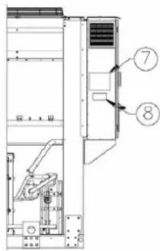
Описание этикеток
Описание этикеток
natural_image
Technical line drawing of a mechanical device suspended by crane, with two inset views showing internal components (no text or symbols)natural_image
Technical line drawing of a mechanical lifting device with inset close-ups showing internal components (no text or symbols)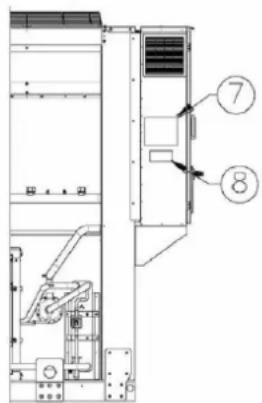
natural_image
Technical line drawing of a mechanical device suspended by crane, with two inset views showing internal components (no text or symbols)natural_image
Technical line drawing of a mechanical lifting device with two inset views showing internal components (no text or symbols)
natural_image
Technical line drawing of a mechanical device suspended by crane, with two inset views showing internal components (no text or symbols)natural_image
Technical line drawing of a mechanical lifting device with two inset views showing internal components (no text or symbols)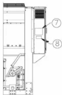
Tarran tunnistus
Tarran tunnistus
natural_image
Technical line drawing of a mechanical device suspended by crane, with two inset views showing internal components (no text or symbols)natural_image
Technical line drawing of a mechanical lifting device with two inset views showing internal components (no text or symbols)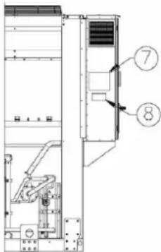
natural_image
Technical line drawing of an industrial machine or control unit with no visible text or symbolsnatural_image
Technical line drawing of a mechanical device suspended by crane, with two inset views showing internal components (no text or symbols)natural_image
Technical line drawing of a mechanical lifting device with inset close-ups showing internal components (no text or symbols)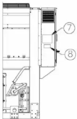
Identifikace štítku
Identifikace štítku
natural_image
Technical line drawing of a mechanical device suspended by crane, with two inset views showing internal components (no text or symbols)6 - 14 ventilátorů
natural_image
Technical line drawing of a mechanical lifting device with inset close-ups showing internal components (no text or symbols)
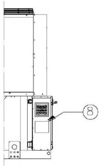
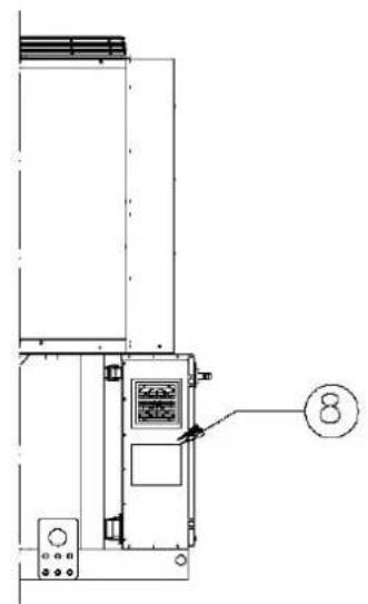
Oznake na etiketi
| 1 – Simbol za nezapaljivi plin | 5 – Upozorenje o stezanju kabela |
| 2 – Vrsta plina | 6 – Simbol o električnoj opasnosti |
| 3 – Proizvođačeva oznaka | 7 – Upute u vezi s podizanjem |
| 4 – Upozorenje o opasnom naponu | 8 – Podaci identifikacijske pločice jedinice |


natural_image
Technical line drawing of an electrical enclosure with labeled component (no text or symbols beyond label)Oznake na etiketi
| 1 – Simbol za nezapaljivi plin | 5 – Upozorenje o stezanju kabela |
| 2 – Vrsta plina | 6 – Upozorenje o opasnom naponu |
| 3 – Podaci identifikacijske pločice jedinice | 7 – Simbol o električnoj opasnosti |
| 4 – Proizvođačeva oznaka | 8 – Upute u vezi s podizanjem |
Slika 2 - Operativna ograničenja – Standardna učinkovitost
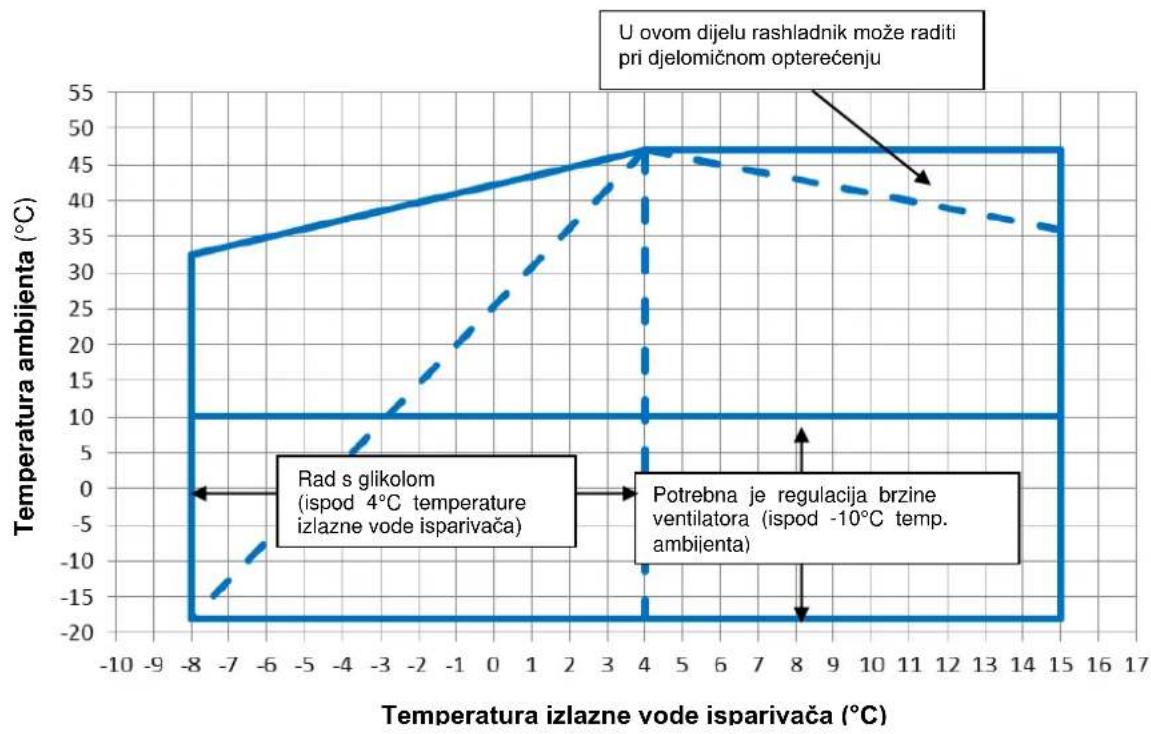
line
| Temperature izlazne vode isparivača (°C) | Temperature ambijenta (°C) | | ---------------------------------------- | -------------------------- | | -8 | 33 | | -7 | 34 | | -6 | 35 | | -5 | 36 | | -4 | 37 | | -3 | 38 | | -2 | 39 | | -1 | 40 | | 0 | 41 | | 1 | 42 | | 2 | 43 | | 3 | 44 | | 4 | 45 | | 5 | 46 | | 6 | 46 | | 7 | 46 | | 8 | 46 | | 9 | 46 | | 10 | 46 | | 11 | 46 | | 12 | 46 | | 13 | 46 | | 14 | 46 | | 15 | 46 | | 16 | 46 | | 17 | 46 |Slika 3. - Operativna ograničenja – Visoka učinkovitost
line
| Temperature izlazne vode isparivača (°C) | Temperature ambijenta (°C) | | ---------------------------------------- | -------------------------- | | -8 | 35 | | 4 | 50 | | 15 | 50 |Slika 4. - Operativna ograničenja – Izuzetna (premium) učinkovitost
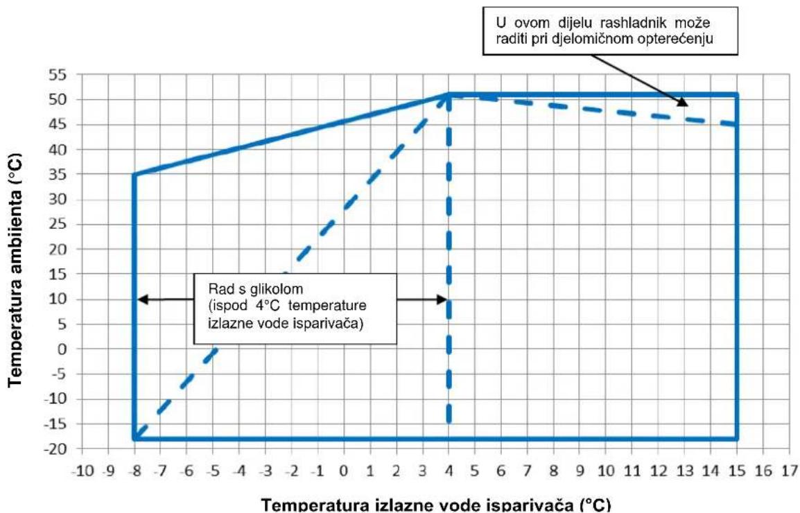
line
| Temperature izlazne vode isparivača (°C) | Temperature ambienta (°C) | | ---------------------------------------- | -------------------------- | | -8 | -20 | | -7 | -15 | | -6 | -10 | | -5 | -5 | | -4 | 0 | | -3 | 5 | | -2 | 10 | | -1 | 15 | | 0 | 20 | | 1 | 25 | | 2 | 30 | | 3 | 35 | | 4 | 40 | | 5 | 45 | | 6 | 50 | | 7 | 50 | | 8 | 50 | | 9 | 50 | | 10 | 50 | | 11 | 50 | | 12 | 50 | | 13 | 50 | | 14 | 50 | | 15 | 50 | | 16 | 50 | | 17 | 50 |Sigurnost
natural_image
Technical line drawing of a mechanical device suspended by crane, with two inset views showing internal components (no text or symbols)verzija s 6-14 ventilatora
(Crtež prikazuje samo verziju sa 6 ventilatora. Za verzije sa 6-8-10-12-14 ventilatora način podizanja je Istl.)
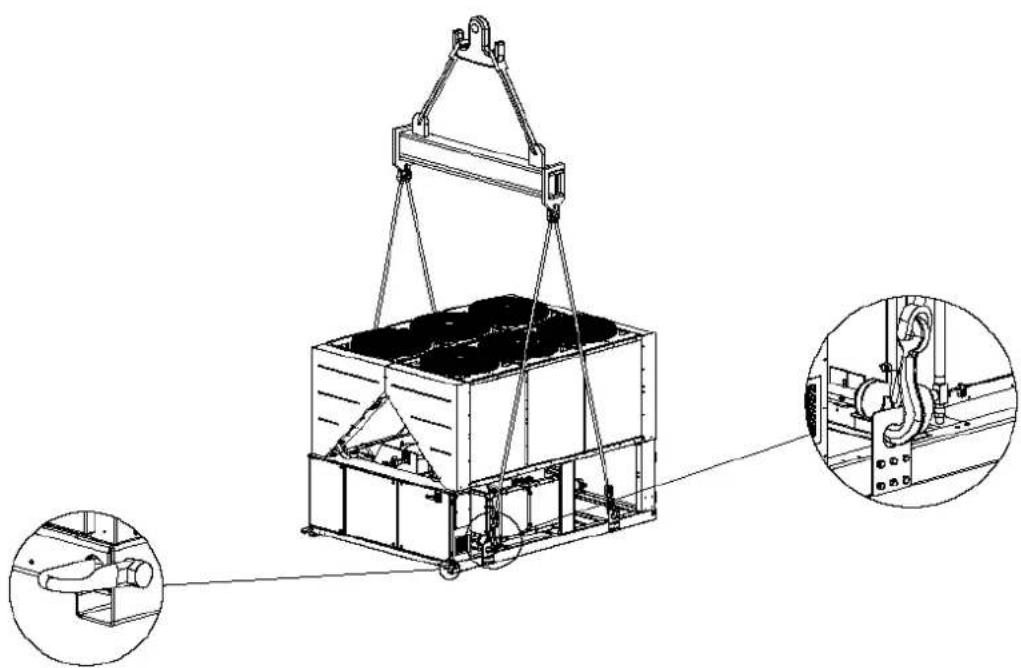
natural_image
Technical line drawing of a mechanical lifting device with two inset views showing internal components (no text or symbols)Za instalaciju na tlu potrebno je snažno betonsko postolje, najmanje debljine 250 mm, šire od jedinice. To postolje mora biti u stanju podnijeti težinu jedinice.
a Sadrži fluorirane stakleničke plinove
b Broj kruga
c Tvorničko punjenje
d Punjenje na terenu

A címke értelmezése
natural_image
Technical line drawing of an electrical enclosure with a circular component and control panel (no text or symbols)A címke értelmezése
natural_image
Technical line drawing of a mechanical device suspended by crane, with two inset views showing internal components (no text or symbols)natural_image
Technical line drawing of a mechanical lifting device with three circular insets showing close-ups of components (no text or symbols)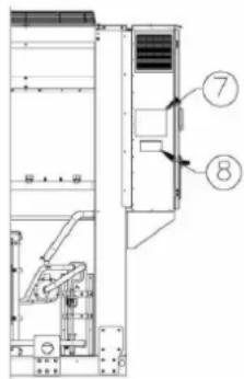
natural_image
Technical line drawing of a mechanical device suspended by crane, with two circular insets showing close-ups of internal components (no text or symbols)natural_image
Technical line drawing of a crane lifting a container, with two circular insets showing close-ups of mechanical components (no text or symbols)
natural_image
Technical line drawing of a mechanical device suspended by crane, with two inset views showing internal components (no text or symbols)verzia so 6 - 14 ventilátormi
natural_image
Technical line drawing of a mechanical lifting device with two inset views showing internal components (no text or symbols)a Vsebuje fluorirane toplogredne pline
b Številka kroga

natural_image
Technical line drawing of an electrical enclosure or control unit with a numbered component (no text or symbols present)line
| Temperature on the overhanging water body on the repertory | Temperature on the red surface at 4°C | Annotation | | :--- | :--- | :--- | | -8 | 35 | | | -7 | 36 | | | -6 | 37 | | | -5 | 38 | | | -4 | 39 | | | -3 | 40 | | | -2 | 41 | | | -1 | 42 | | | 0 | 43 | | | 1 | 44 | | | 2 | 45 | | | 3 | 46 | | | 4 | 47 | | | 5 | 48 | | | 6 | 48 | | | 7 | 48 | | | 8 | 48 | | | 9 | 47 | | | 10 | 46 | | | 11 | 45 | | | 12 | 44 | | | 13 | 43 | | | 14 | 42 | | | 15 | 41 | | | 16 | 40 | | | 17 | 39 | | The chart displays a single line representing 'Temperature on the overhanging water body on the repertory' with a dashed line indicating 'Temperature on the red surface at the same temperature'. The annotation 'B tazni zona oxladiteitant moje da paoboti na частichno natovarbane' appears in the upper right corner. The diagram also includes a box labeled 'Pabota c glikol (pod 4°C na temp. ha izxod. voda ha iznpar.)' below the plot.natural_image
Technical line drawing of a mechanical device suspended by crane, with two inset views showing internal components (no text or symbols)natural_image
Technical line drawing of a mechanical lifting device with two inset views showing internal components (no text or symbols)other
| Section | Value | | ------- | ----- | | Top Section | 1500 | | Bottom Section | 1800 |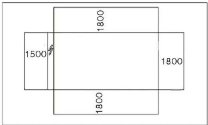

Identifikacija nalepke
| 1 – Simbol nevnetljivega plina | 5 – Opozorilo glede privitosti vodnikov |
| 2 – Vrsta plina | 6 – Simbol nevarne električne napetosti |
| 3 – Logotip proizvajalca | 7 – Navodila za dvigovanje |
| 4 – Nevarna napetost | 8 – Identifikacijska ploščica enote |
Identifikacija nalepke
| 1 – Simbol nevnetljivega plina | 5 – Opozorilo glede privitosti vodnikov |
| 2 – Vrsta plina | 6 – Nevarna napetost |
| 3 – Identifikacijska ploščica enote | 7 – Simbol nevarne električne napetosti |
| 4 – Logotip proizvajalca | 8 – Navodila za dvigovanje |
natural_image
Technical line drawing of a mechanical device suspended by crane, with two inset views showing internal components (no text or symbols)natural_image
Technical line drawing of a mechanical lifting device with two inset views showing internal components (no text or symbols)a Vsebuje fluorirane toplogredne pline
b Številka kroga
The present publication is drawn up by of information only and does not constitute an offer binding upon Daikin Applied Europe S.p.A.. Daikin Applied Europe S.p.A. has compiled the content of this publication to the best of its knowledge. No express or implied warranty is given for the completeness, accuracy, reliability or fitness for particular purpose of its content, and the products and services presented therein. Specification are subject to change without prior notice. Refer to the data communicated at the time of the order. Daikin Applied Europe S.p.A. explicitly rejects any liability for any direct or indirect damage, in the broadest sense, arising from or related to the use and/or interpretation of this publication. All content is copyrighted by Daikin Applied Europe S.p.A..