UATYA70BFC3Y1 - Air Conditioning DAIKIN - Free user manual and instructions
Find the device manual for free UATYA70BFC3Y1 DAIKIN in PDF.

| Product Type | Monobloc rooftop air conditioner |
| Brand | Daikin |
| Model | UATYA70BFC3Y1 |
| Controller | cPCO with 4.3" touch screen |
| Main functions | Cooling, heating (mechanical and auxiliary), humidification, dehumidification, free cooling, damper management |
| Setpoint management | Dynamic with outdoor temperature compensation |
| Temperature control | Proportional, cascade, PID |
| Humidity control | Relative or absolute, proportional |
| Alarm management | Complete table with codes (AL1 to AL259) |
| Communication | BMS, external signals, USB key |
| Time schedules | Up to 4 programmable schedules with offsets |
| Auxiliary heating | Electric heaters, hot water coil, buffer tank, burner |
| Fast Restart function | Fast restart after blackout (ultracap) |
| Anti-freeze function | For hot water coil and buffer tank |
| Maintenance | Filter cleaning, manual humidifier drain, pre-wash |
| Safety | Phase protection, min/max voltage, pressure and temperature alarms |
| Repairability | Accessible components, technical documentation available |
| General information | 356-page PDF manual, multiple languages |
Frequently Asked Questions - UATYA70BFC3Y1 DAIKIN
User questions about UATYA70BFC3Y1 DAIKIN
0 question about this device. Answer the ones you know or ask your own.
Ask a new question about this device
Download the instructions for your Air Conditioning in PDF format for free! Find your manual UATYA70BFC3Y1 - DAIKIN and take your electronic device back in hand. On this page are published all the documents necessary for the use of your device. UATYA70BFC3Y1 by DAIKIN.
USER MANUAL UATYA70BFC3Y1 DAIKIN
Rooftop Packaged Unit
R-32 rooftop series – Base, 2-,3- and 4-damper versions
Made-To-Stock models
UATYA-BBAY1
UATYA-BBC2Y1
UATYA-BBC3Y1
Made-To-Order models
BASE
FC2
FC3
FC4
Operation manual
Rooftop Packaged Unit
Bedienungsanleitung
natural_image
Blank grid paper with uniform gray squares on white background (no text or symbols)Contents
1 Introduction 5
1.1 General 5
1.1.1 c.pCO controller functions 5
2 Quick commissioning 6
2.1 Main functions 6
2.2 Switching the unit on and off 6
2.2.1 Switch the unit on and off from the display. 6
2.2.2 Switch the unit on and off from external OK signal 6
2.2.3 Switch the unit on and off from the BMS 6
2.3 Change of set points 7
2.3.1 Setpoint editing from display 7
2.3.2 Setpoint editing from BMS 7
2.4 Change language 7
2.5 Changing the date and time 8
2.6 Setting of time bands 8
3 Graphics on the display 9
3.1 Graphic conventions 9
3.1.1 Icons and symbols 9
4 The screens 11
4.1 Screen tree 11
4.1.1 Screen menu 12
4.2 Menu browsing 13
4.2.1 Info 13
4.2.2 Demand 13
4.2.3 Synoptic panel 14
4.2.4 Login 15
5 Software functions 16
5.1 Introduction 16
5.2 Set point management 17
5.2.1 Dynamic Set Point 17
5.2.2 Dynamic setpoint from external air probe in cooling mode 18
5.2.3 Dynamic setpoint from external air probe in heating mode 19
5.3 Temperature control 20
5.3.1 Thermoregulation in cooling mode 21
5.3.2 Thermoregulation in heating mode 23
5.3.3 Disabling heating sources depending on external air temperature 25
5.4 humidity control 26
5.4.1 Relative humidity control with proportional control 27
5.5 Air humidification 28
5.5.1 Ancillary built-in humidifier functions 28
5.6 Air dehumidification 28
5.7 Power supply control 29
5.7.1 Phase sequence 29
5.7.2 Min. / Max. voltage 29
5.7.3 Fast Restart 29
5.8 Damper management 30
5.8.1 Damper control 31
5.8.2 Damper management 31
5.8.3 Unit start-up 31
5.8.4 Washing 31
5.8.5 Recirculation 32
5.9 Auxiliary heating 33
5.9.1 Controlled devices 34
5.9.2 Post heating 34
5.9.3 Activation according to time bands
5.1 Introduction 36
5.2 Alarm table 36
1.1 General
Some information on the use of this manual.
The purpose of this manual is to provide all the necessary information for the use of the controller and relevant software application in the units indicated on the cover.
Information regarding installation of the units and relevant tests and checks for the first starting is not given in this manual.
We thank in advance all those who will wish to let us know of any errors, omissions, sections requiring further explanation or operations that have not been included.
1.1.1 c.pCO controller functions
The software application for the electronic microprocessor controller, series c.pCO, was designed to manage Rooftop units.
Through appropriate configuration, this gives the possibility of managing a wide range of units with relevant specific functionalities.
Management of Rooftop units means monitoring that all component parts operate safely throughout the various operating cycles.
The family of c.pCO electronic microprocessor controllers includes various module sizes. The software is flexible to the extent that the use of modules is optimized, meaning the modules used for reach application are those having the necessary number of inputs and outputs.
The c.pCO board is connected to the various modules and communicates with them via a high speed, highly reliable field bus.
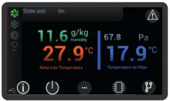
The controller user interface consists in a colour, 4.3" touch-screen display.
2.1 Main functions
The necessary instructions for working on the controller, with regard to the main functions of the unit, are given below.
2.2 Switching the unit on and off
2.2.1 Switch the unit on and off from the display.
Use the "On/Off" icon on the main screen to go to the page where the buttons to start and stop the unit are featured.
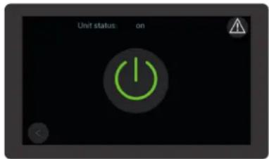
The top area of the screen shows the status of the unit: the "On/Off" icon is provided in the central area. A tap on the icon changes the status of the unit from "on" to "off" and vice versa.
2.2.2 Switch the unit on and off from external OK signal
In order to switch the unit on and off from external OK signal, make sure the feature is active. To switch the unit on, close the external OK signal. To switch it off, open it. The external OK signal should be connected to terminals "1" and "56" in the terminal board. In order to switch the unit on and off from external OK signal, make sure the feature is active. To switch the unit on, close the external OK signal. To switch it off, open it. The external OK signal should be connected to terminals "1" and "2" present in the terminal board.

The external OK signal must be a potential-free contact.
2.2.3 Switch the unit on and off from the BMS
In order to switch the unit on and off from the BMS, make sure the feature is active. See dedicated BMS management document.
2.3.1 Setpoint editing from display
Go to the main menu and press "Setpoint" to access the screens where functions are displayed whose setpoints need to be managed.
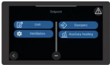
Go to the "Setpoint" sub menu and select the function whose setpoint is to be changed.
Scroll the parameters until the desired parameter setpoint is achieved.
Select the setpoint parameter to enable the edit keypad.
Set the new value and apply the green tick to confirm.
Units featuring mode switching have a setpoint for cooling "ST7" and a setpoint for heating "STH7".
The setpoint for cooling "ST7" must necessarily be higher than the setpoint for heating "STH7".
If values that do not meet this condition are set by mistake, the controller activates alarm "AL183".
Alarm "AL183" is displayed for warning purposes only.
2.3.2 Setpoint editing from BMS
Setpoints can be edited from the BMS only if this function is enabled.
See dedicated BMS management document.
2.4 Change language
When in the main menu, press "Languages" to access the screens in which the available languages are displayed.

If the language you are looking for is not in the screen, use the arrows to find it.
The selected language becomes active as soon as it is selected.
2.5 Changing the date and time
Scroll the main menu until you find the "Configurations" group and select it.
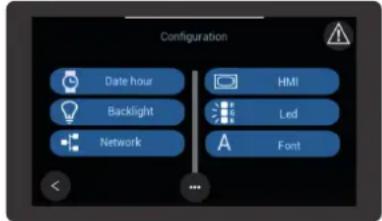
Select "Date and Time" in the "Configurations" menu and access the screen where it is possible to edit the date and time setpoints.
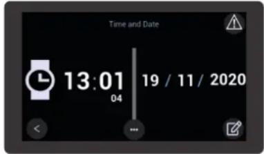
Select the write icon in the bottom right-hand side to access the edit screen.
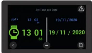
When a green value is tapped, a virtual keypad appears: use the keypad to set the new values. After entering the new value, tick it to confirm it.
After changing the values, tap the Save icon on the bottom right-hand side to save the new setpoints.
The arrow on the left is used to go back to the previous screen without saving the changed parameters.
2.6 Setting of time bands
Access to the screen where the time bands are set up requires entry of a password.
Scroll the main menu until you find the "Parameters" group and select it.
Scroll the "Parameters" menu until you find the "ES Energy saving" group.
After selecting “ES Energy saving”, access is gained to the group of parameters used to set up the time bands. Refer to the relevant chapter for more information on the parameter setup logic.
During development of the application, particular attention was given to intuitive use of the user interface.
3.1 Graphic conventions
The touch-screen display is designed to browse the interface.
Provision has been made for some intuitive icon buttons that are tapped to easily browse the featured screens and menus.
Other user-friendly symbols are used to locate parts and active functions.
Below is a list of the icons used as buttons and the symbols featured in the various screens of the interface.
3.1.1 Icons and symbols
Icons are used as physical buttons in the touch-screen display to browse the menus and screens. The featured icons include:

“Home” - this icon is pressed to go back to the Home page. The arrow buttons are pressed to move within the given loop;

“Info” - this icon gives access to the screens containing information on both the software and the unit; The arrow buttons are pressed to move within the given loop;

"On/Off" - this icon gives access to the screen used to switch the unit on or off from the user interface;

"Cooling/Heating" This icon gives access to the screen where the unit operating mode is switched from cooling to heating using the user interface.

“Menu” - pressing of this icon on the Home page gives access to the “Menu” screen. If this icon is pressed on any other screen, the system moves back by one level;

“Demand” - this icon gives access to the screens where the various demands from the system are displayed; The arrow buttons are pressed to move within the given loop;

“Dampers” This icon gives access to the screens where the operating status of the dampers is displayed. The arrow buttons are pressed to move within the given loop;

"Synoptic panel" - this icon gives access to the screen where the layout showing the operating principle of the circuit featured in the unit is displayed. A tap on the circuit components gives access to the relevant information and parameters.

A click on this icon gives access to the Alarms menu. If the icon is red, at least one alarm is active; no alarm is active if it is grey.

A click on this icon either enables or disables the function it is associated with.

A click on this icon enables movement to the left within one screen loop.

A click on this icon enables movement to the right within one screen loop.

This icon appears in the "login" screen after entering the "password". A click on this icon confirms the entered "password".

This icon appears in the "login" screen and it is accessed with the correct credentials. A click on this icon enables moving back to the "loop" of the previous menu, gaining access to it with the active credentials.
Some symbols help easily understand the functions featured in the unit and their status. Symbols include:

this symbol is featured in all units and it indicates the ventilation function. When it is grey, the ventilation unit is not operational and it is when the symbol is coloured.

this symbol indicates the cooling function. When it is grey, the cooling unit is not operational and it is when the symbol is coloured.

this symbol indicates the humidification function. When it is grey, the humidification unit is not operational and it is when the symbol is coloured.

this symbol indicates the de-humidification function. When it is grey, the de-humidification unit is not operational and it is when the symbol is coloured.

this symbol indicates that access is now active after login to pages containing protected parameters. Access to some parameters requires entry of a password which depends on the profile for which the user is accredited.

this symbol indicates the connection with a USB pen drive. The symbol appears when data transmission is in progress.

This symbol indicates that the unit is operating in heating mode. The symbol is common for both main and auxiliary sources. If the symbol is orange it means that the main source is working. If the symbol is yellow it means that the auxiliary source is working. If the symbols are gray it means that the sources are not working.


The user interface gives access to all information and setup parameters relating to unit operation. The manual describes the access procedure to the desired information and to the parameter pages where the various functions can be set up.
4.1 Screen tree
The user interface gives access to all information and setup parameters relating to unit operation. The manual describes the access procedure to the desired information and to the parameter pages where the various functions can be set up.
As explained in the description of icons, the home page gives direct access to the most significant information and functions. Most parameters and settings are featured in the screen, which are broken down in one main menu and various sub-menus.
A tree diagram of the screens is provided below to help the user browse and easily locate the screens of the user interface.
- Setpoint
* Unit
* Ventilation
* Humidification Dehumidification
* Dampers
* Auxiliary heating
* Post-heating g
* Environment air renewal
- Probes
- 1/0
* Universal inputs
* Digital inputs
* Driver 1
* Analog outputs
* Digital outputs
* Driver 2
- Language
* English
* Italian
* Swedish
* German
* French
* Spanish
* Polish
- Alarm history
- Charts
- Login
- Configuration
* Date hour
* Backlight
* Network
* HMI
* Led
* Font
- Parameters
* ST - Mechanical cooling
* STH - Mechanical heating
* SFA - Temperature control ventilation
* SP - Setup
* FA - Supply ventilation
* RFA - Return ventilation
* PAL - Alarms
* CF - Configuration
* CO - Compressors
* ET - Electronic thermostatic valve
* PID - PID parameters
* ES - Energy Saving
* UN - Unloading
* DF - Defrost
* HU - Humidity
* PD - Pump Down
* SD - Dynamic setpoint
* DA - Dampers
* EFA - External ventilation
* CA - Calibration probes
* RA - Transducer probe full scale
* ENV - Envelope
- Files management
* Saving timelog.txt
* Upload default.conf
* Upload alarm.conf
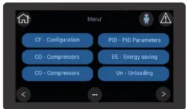
4.1.1 Screen menu
A click on the "Menu" button in the home page gives access to the main menu.
The arrow icon buttons featured in the main menu are used to scroll all lower level menus.
Access to lower level menus is allowed based on the user's credentials. Some users have free access, while others have to log in with the profile they are accredited for.
Access to the various menus is gained by clicking the colour area containing the menu description.
For easier understanding and use, texts are shown to explain the meaning of the values and parameters featured in the screens.
4.2 Menu browsing
The screen tree helps the operator to browse the menus.
Some other suggestions are given to help use the icon buttons to browse the screens.
The home page is the starting point.

Refer to the chapter titled "Graphic Conventions" for the interpretation and use of the icon buttons.
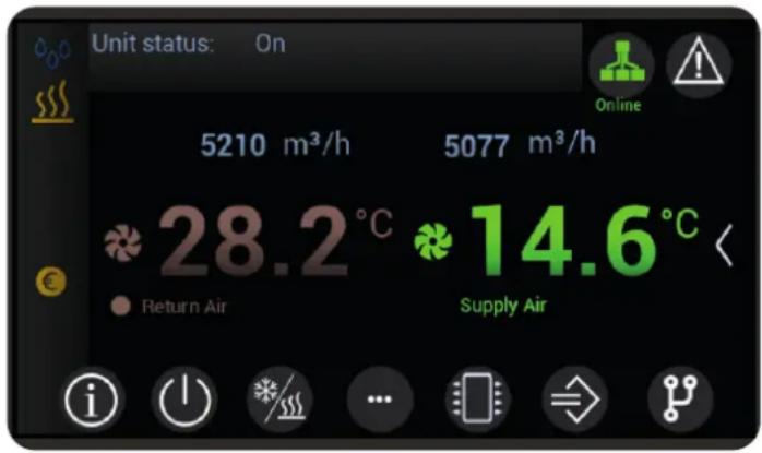
In addition to the “On/Off” icon, the main page features icons such as “Info”, “Demand” and “Synoptic Panel”, which give direct access to information loops. The page also features the “Menu” icon which gives access to the main menu contained in the screen tree.
The arrow icon buttons are pressed to scroll screens of the same level, while a click on the "Menu" icon brings back to a higher level.
Parameter screens show editable parameters with white wording and view-only parameters with cyan wording.
A click on white parameters calls up the relevant edit screen. The parameter value is confirmed when ticked and it is deleted when marked with symbol "x", in which case the last setpoint is restored.
Parameters referred to function enabling/disabling are activated/de-activated by moving the white circle. The status confirmation is visible along the parameter.
For easier consultation, many parameters and measured values are featured in multiple screen loops, grouped by uniform functions.
4.2.1 Info
The “Info” icon on the home page gives access to a screen loop containing information on the unit.
4.2.2 Demand
The “Demand” icon on the home page gives access to a screen loop containing information on the demand status of the active functions in the unit.
The relevant setpoints are visible in the various demand screens.
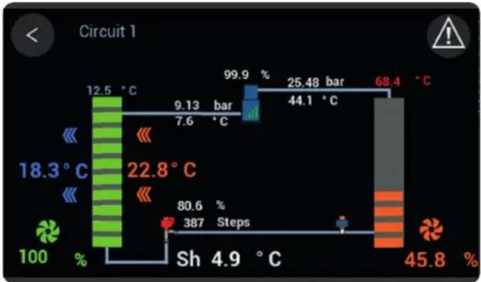
4.2.3 Synoptic panel
The "Synoptic Panel" icon gives access to the corresponding menu.
The synoptic panel is designed to show an overview of the operating status and of the main parameters.
Screens vary according to the features of each unit.
other
Circuit 1 | Process | Temperature (°C) | Percentage (%) | | :--- | :--- | :--- | | Top Left | 12.5 | 100 | | Top Right | 9.13 | 7.6 | | Bottom Left | 99.9 | 80.6 | | Bottom Right | 25.48 | 387 | | Bottom Right | 44.1 | 45.8 | | Bottom Right | 68.4 | 45.8 | Sh 4.9 °CThe "Info" icons in the screens give access to the information and parameters of the corresponding component.
4.2.4 Login
The user must log in with his own profile in order to access reserved menus and to edit the featured parameters. Below is the login procedure.
- Select the access level corresponding to the given credentials.
- Click "password" and enter the value corresponding to the given access level, then tick to confirm.
- Confirm the password tapping the green arrow icon button on the bottom right-hand side.

User "password" is "100"
Service "password" is "4321"
If the entered password is correct, the padlock opens and the access symbol appears, based on the level.
Tap the green arrow icon button on the bottom left-hand side to go back to the main menu.


The little man icon with the arrow on the left causes the system to exit the access level.
The symbol stays on the top right-hand side of all screens, except for the home page, until access is active. The system exits the login automatically after an idle time shown on the display.
5.1 Introduction
For management of the units, special software is loaded into the controller.
The software consists of a combination of functions dedicated to the conditions in which the units may have to work.
The following chapters describe all the functions managed by the software, ranging from ordinary functions featured in all units to functions dedicated to specific versions or models.

Some of the functions described here may be available only on specific versions or sizes, or according to the selected accessories.
In describing the various functions, competence in operation of the units and knowledge of the relevant hydraulic or refrigerant circuits are taken for granted. All the descriptions, settings and parameters given refer to units that are correctly installed as described in the relevant documentation.
5.2 Set point management
The control setpoint mainly depends on parameters "ST1" and "STH1".
The relevant settable minimum and maximum setpoint parameters are shown below.
| Parameter Min Max | UM Description | |||
| ST1 ST2 ST3 ^ Mechanical cooling - Temperature setpoint | ||||
| STH1 STH2 STH3 ^ | Mechanical heating / Auxiliary heating in winter mode - Temperature setpoint | |||
Provision has been made for ancillary functions that are designed to either add or subtract an offset value to/from these setpoints.

Any automatic variation of the setpoint must be within the corresponding limits.

Parameter "SD2" is used to set the operating mode in which setpoint variation is enabled. There is only one function available and this is the function enabled at the factory.
5.2.1 Dynamic Set Point
The dynamic set point is a function enabled by the manufacturer.
The reference parameters in managing the dynamic set point are described below.
| Parameter Min Max | UM Description | |||
| ST1 ST2 ST3 | °C Mechanical cooling - Temperature setpoint | |||
| STH1 STH2 STH3 °C | Mechanical heating / Auxiliary heating in winter mode - Temperature setpoint | |||
| SD2 | 0 | 2 | - | States of the unit in which it is active |
| SD10 | 0.0 | 55.0 | °C | Mechanical cooling - External air temperature - Activation threshold for compensation |
| SD20 | 0.0 | 55.0 | °C | Mechanical heating - External air temperature - Activation threshold for compensation |
5.2.2 Dynamic setpoint from external air probe in cooling mode
The setpoint value entered in parameter "ST1" is "compensated" against the external air temperature.
The parameters concerned are shown in the table.

The values of the parameters are representative. In specific cases, different values can be set.
| Parameter Value UM | Description | ||
| ST1 27.0 °C Mechanical | cooling - | Temperature setpoint | |
| SD2 1 - States of the unit in which | it is active | ||
| SD10 25.0 °C | Mechanical cooling - External air temperature - Activation threshold for compensation | ||
A graphical representation is shown below.
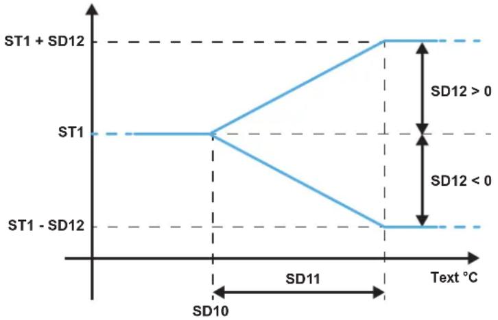
Fig. 1 Change in setpoint as the air temperature changes in cooling mode
Where "Text" is the value of the external air temperature.
When this function is enabled, the setpoint value that the controller uses to manage the air temperature in cooling mode is as follows:
- if the external air temperature is lower than the setpoint in parameter "SD10", the value of the control setpoint is the value stored in parameter "ST1";
- if the external air temperature is higher than the setpoint in parameter "SD10", plus the value in parameter "SD11", the value of the control setpoint is given by the sum of the values stored in parameters "ST1" and "SD12";
- if the external air temperature is between the values of parameter "SD10" and the sum of the values stored in parameters "SD10" and "SD11", the value of the control setpoint varies proportionally between the value stored in parameter "ST1" and the sum of the values stored in parameters "ST1" and "SD12".

Parameter “SD12” can have positive or negative values. When the value is negative, parameter “SD12” has to be subtracted from the value of parameter “ST1”.
5.2.3 Dynamic setpoint from external air probe in heating mode
The setpoint value entered in parameter "STH1" is "compensated" against the external air temperature.
The parameters concerned are shown in the table.

The values of the parameters are representative. In specific cases, different values can be set.
| Parameter Value UM | Description | ||
| STH1 40 °C Mechanical | heating / | Auxiliary heating in winter mode - Temperature setpoint | |
| SD20 15.0 °C | Mechanical heating - External air temperature - Activation threshold for compensation | ||
| SD21 10.0 °C | Mechanical heating | - External air temperature - Activation differential | |
| SD22 5.0 °C | Mechanical heating - External air temperature - Max increase / decrease of the setpoint | ||
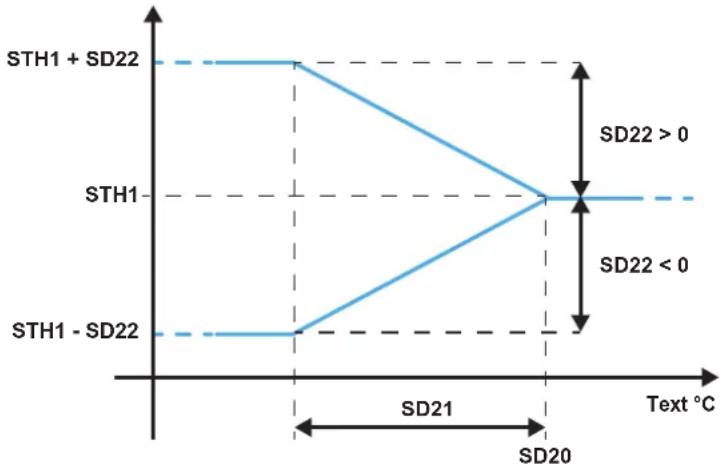
A graphical representation is shown below.
line
| Text °C | STH1 + SD22 | STH1 - SD22 | | ------- | ----------- | ----------- | | 0 | 0 | 0 | | 20 | 0 | 0 |Fig. 2 Change in setpoint as the air temperature changes in heating mode
Where "Text" is the value of the external air temperature.
When this function is enabled, the setpoint value that the controller uses to manage the air temperature in heating mode is as follows:
- if the external air temperature is higher than the setpoint in parameter "SD20", the value of the control setpoint is the value stored in parameter "STH1";
- if the external air temperature is lower than the setpoint in parameter "SD20", minus the value in parameter "SD21", the value of the control setpoint is given by the sum of the values stored in parameters "STH1" and "SD22";
- if the external air temperature is between the values of parameter "SD20" and the difference of the values stored in parameters "SD20" and "SD21", the value of the control setpoint varies proportionally between the value stored in parameter "STH1" and the sum of the values stored in parameters "STH1" and "SD22".

Parameter "SD22" can have positive or negative values. When the value is negative, parameter "SD22" has to be subtracted from the value of parameter "STH1".
5.3 Temperature control
Cooling and heating devices are controlled according to the temperature value measured by a reference probe.
The proportional band identifies the control range of the air conditioner system and it can be set up with independent values for heating and cooling mode.
The dead zone identifies the range around the setpoint within which the devices are not enabled (it is used to prevent oscillations in the setup value).
The diagram below shows the behaviour of heating and cooling devices.

line
| SdR °C | Value (%) | | ------ | --------- | | STH1 | 100 | | STH2 | 0 | | STH3 | 0 | | STH4 | 0 | | STH5 | 0 | | STH6 | 0 | | STH7 | 0 | | STH8 | 0 | | STH9 | 0 | | STH10 | 0 | | STH11 | 0 | | STH12 | 0 | | STH13 | 0 | | STH14 | 0 | | STH15 | 0 | | STH16 | 0 | | STH17 | 0 | | STH18 | 0 | | STH19 | 0 | | STH20 | 0 | | STH21 | 0 | | STH22 | 0 | | STH23 | 0 | | STH24 | 0 | | STH25 | 0 | | STH26 | 0 | | STH27 | 0 | | STH28 | 0 | | STH29 | 0 | | STH30 | 0 | | STH31 | 0 | | STH32 | 0 | | STH33 | 0 | | STH34 | 0 | | STH35 | 0 | | STH36 | 0 | | STH37 | 0 | | STH38 | 0 | | STH39 | 0 | | STH40 | 0 | | STH41 | 0 | | STH42 | 0 | | STH43 | 0 | | STH44 | 0 | | STH45 | 0 | | STH46 | 0 | | STH47 | 0 | | STH48 | 0 | | STH49 | 0 | | STH50 | 0 | | STH51 | 0 | | STH52 | 0 | | STH53 | 0 | | STH54 | 0 | | STH55 | 0 | | STH56 | 0 | | STH57 | 0 | | STH58 | 0 | | STH59 | 0 | | STH60 | 0 | | STH61 | 0 | | STH62 | 0 | | STH63 | 0 | | STH64 | 0 | | STH65 | 0 | | STH66 | 0 | | STH67 | 0 | | STH68 | 0 | | STH69 | 0 | | STH70 | 0 | | STH71 | 0 | | STH72 | 0 | | STH73 | 0 | | STH74 | 0 | | STH75 | 0 | | STH76 | 0 | | STH77 | 0 | | STH78 | 0 | | STH79 | 0 | | STH80 | 0 | | STH81 | 0 | | STH82 | 0 | | STH83 | 0 | | STH84 | 0 | | STH85 | 0 | | STH86 | 0 | | STH87 | 0 | | STH88 | 0 | | STH89 | 0 | | STH90 | 0 | | STH91 | 0 | | STH92 | 0 | | STH93 | 0 | | STH94 | 0 | | STH95 | 0 | | STH96 | -1 | | STH6 | -1 | | STH7 | -1 | | STH8 | -1 | | STH9 | -1 | | STH1 | -1 | | STH2 | -1 | | STH3 | -1 | | STH4 | -1 | | STH5 | -1 | | STH6 | -1 | | STH7 | -1 | | STH8 | -1 | | STH9 | -1 | | STH1 | -1 | | STH2 | -1 | | STH3 | -1 | | STH4 | -1 | | STH5 | -1 | | STH6+ | -1 |Fig. 3 Graphical representation of temperature control devices
| Parameter Min Max | UM Description | |||
| ST1 ST2 ST3 | °C Mechanical cooling - Temperature setpoint | |||
| ST4 0.0 25.0 | °C Proportional control - Cooling - Activation differential | |||
| ST5 0.0 25.0 | °C Proportional control - Cooling - Neutral activation area | |||
| ST6 0.0 25.0 | °C Proportional control - Cooling - Offset | |||
| ST9 0 7 - Control probe | ||||
| ST11 | 0 2 - Type of temperature control | |||
| PID70 | 0 10000 | - Mechanical cooling - Kp | ||
| PID71 | 0 10000 | - Mechanical cooling - Ki | ||
| PID72 | 0 10000 | - Mechanical cooling - Kd | ||
| PID76 | 0.0 25.0 | °C Mechanical cooling - Dead band | ||
| PID78 | 0 2 - Mechanical cooling - Dead band position | |||
| STH1 | 10.0 35.0 | °C | Mechanical heating / Auxiliary heating in winter mode - Temperature setpoint | |
| STH4 | 0.0 | 25.0 | °C | Mechanical heating - Proportional - Activation differential |
| STH5 | 0.0 | 25.0 | °C | Mechanical heating - Proportional - Activation neutral zone |
| STH6 | 0.0 25.0 | °C Mechanical heating - Proportional - Offset | ||
The values set in parameters "ST9" for cooling and "STH9" for heating determine the control probe type, as follows:
- 0 = temperature probe on air delivery line;
- 1 = temperature probe on air return line;
The values set in parameters “ST11” for cooling and “STH11” for heating determine the type of temperature control, as follows:
- 0 = proportional.
- 1 = "Cascade";
- 2 = PID.
5.3.1 Thermoregulation in cooling mode
The thermoregulation of the unit depends on parameter "ST9", which identifies the reference probe for the temperature setpoint (parameter "ST1"), and on parameter "ST11" which determines the type of temperature/humidity control.
In proportional control mode, the controller activates the available resources as the value read by the reference probe increases in comparison to the setpoint value.
When “Cascade” temperature/humidity control is selected, the controller uses it to enable the resources and at the same time monitor the air temperature in the delivery line.
In PID control mode, the controller activates the available resources as the demand increases. The controller calculates the demand and checks the value measured by the probe against the setpoint value and according to its variation over time using the parameters set in the PID.
Proportional temperature control
If parameter "ST11" is set to "0", proportional control is enabled.
The parameters involved in proportional temperature control are shown in the table.

The values of the parameters are representative. In specific cases, different values can be set.
| Parameter Value UM | Description |
| ST1 24.0 °C Temperature setpoint | |
| ST4 2.0 °C Proportional | control - Cooling - Activation differential |
| ST5 0.1 °C Proportional | control - Cooling - Neutral activation area |
| ST6 0.1 °C Proportional | control - Cooling - Offset |
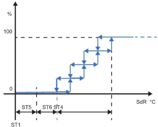
A graphical representation is shown below.
line
| SdR (°C) | Value (%) | |---|---| | ST1 | 0 | | ST5 | 0 | | ST6 | 20 | | ST4 | 30 | | ST6 | 40 | | ST6 | 50 | | ST6 | 60 | | ST6 | 70 | | ST6 | 80 | | ST6 | 90 | | ST6 | 100 | | ST6 | 100 | | ST6 | 100 | | ST6 | 100 | | ST6 | 100 | | ST6 | 100 | | ST6 | 100 | | ST6 | 100 | | ST6 | 100 | | ST6 | 100 | | ST6 | 100 | | ST6 | 105 | | ST6 | 105 | | ST6 | 105 | | ST6 | 105 | | ST6 | 105 | | ST6 | 105 | | ST6 | 105 | | ST6 | 105 | | ST6 | 105 | | ST6 | 105 | | ST6 | 105 | | ST6 | 105 |Fig. 4 Graphical representation of cooling demand
In addition to the parameters listed in the table, the abbreviations in the graph are:
- SdR = reference probe;
- % = percentage demand value.
"cascade" temperature control.
If parameter "ST11" is set to "1", "Cascade" control is enabled.
This function fulfils the system demand and keeps the air temperature in the delivery line within comfort values.
For this purpose, a virtual setpoint is calculated from the stored setpoint, as corrected with the air temperature in the return line.
The setpoint is corrected dynamically as the air temperature changes in the delivery line.
The parameters involved in cascade temperature control are shown in the table.

The values of the parameters are representative. In specific cases, different values can be set.
| Parameter Value UM | Description | ||
| ST42 24.0 °C | Cascade control - Unit setpoint | ||
| ST43 0.5 °C | Mechanical cooling - | Cascade control - Mode switching offset | |
| ST44 4.0 °C | Mechanical cooling - | Cascade control - Operating differential | |
| ST45 15.0 °C | Mechanical cooling | - Cascade control - Min. delivery setpoint | |
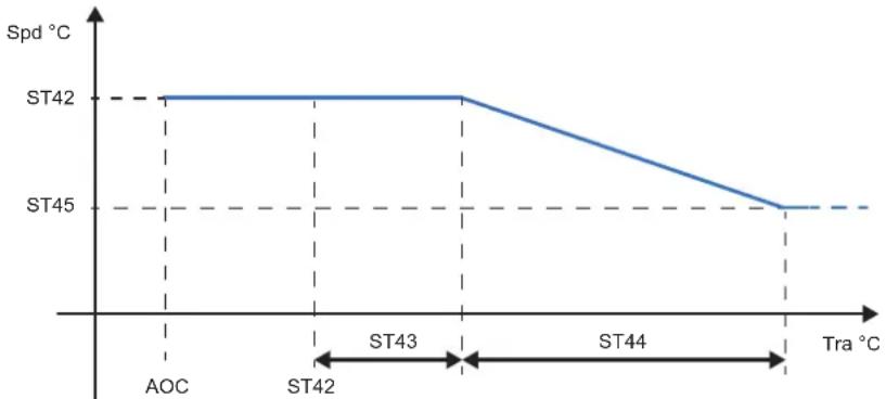
The graph below illustrates cascade control.
line
| Tra °C | Spd °C | |---|---| | AOC | ST42 | | ST42 | ST42 | | ST43 | ST42 | | ST44 | ST45 | | Tra | ST45 |Fig. 5 Change of air delivery setpoint with "cascade" control in cooling mode
In addition to the parameters listed in the table, the abbreviations in the graph are:
- Spd = air setpoint in delivery line;
- Tra = air temperature in return line;
- AOC = automatic mode switching.
5.3.2 Thermoregulation in heating mode
The thermoregulation of the unit in heating mode depends on parameter "STH9", which identifies the reference probe for the temperature value in the setpoint (parameter "STH1"), and on parameter "STH11" which determines the type of temperature control.
In proportional control mode, the controller activates the available resources as the value read by the reference probe decreases in comparison to the setpoint value.
When “Cascade” control is selected, the controller enables the resources and at the same time monitors the air temperature in the delivery line.
In PID control mode, the controller activates the available resources as the demand increases. The controller calculates the demand and checks the value measured by the probe against the setpoint value and according to its variation over time using the parameters set in the PID.
Proportional temperature control
If parameter "STH11" is set to "0", proportional control is enabled.
The parameters involved are shown in the table.

The values of the parameters are representative. In specific cases, different values can be set.
Parameter Value UM Description
| STH1 20.0 °C Mechanical heating / Auxiliary heating in winter mode - Temperature setpoint | |||
| STH4 2.0 °C Mechanical heating - Proportional - Activation differential | |||
| STH5 0.0 °C Mechanical heating - Proportional - Activation neutral zone | |||
| STH6 0.0 °C Mechanical heating - Proportional - Offset |
A graphical representation is shown below.

line
| SdR °C | Value (%) | | ------ | --------- | | -2.5 | 100 | | -1.5 | 80 | | -0.5 | 60 | | 0 | 40 | | 1.5 | 20 | | 2.5 | 0 |Fig. 6 Graphical representation of stepped heating demand
In addition to the parameters listed in the table, the abbreviations in the graph are:
- SdR = reference probe;
- % = percentage demand value.
Temperature monitoring with Cascade control
If parameter "ST11" is set to "1", "Cascade" control is enabled.
This function fulfils the system demand and keeps the air temperature in the delivery line within comfort values.
For this purpose, a virtual setpoint is calculated from the stored setpoint, as corrected with the air temperature in the return line.
The setpoint is corrected dynamically as the air temperature changes in the delivery line.
The parameters involved in cascade temperature control are shown in the table.

The values of the parameters are representative. In specific cases, different values can be set.
Parameter Value UM Description
| ST42 24.0 °C | Cascade control - Unit setpoint |
| STH46 0.5 °C | Mechanical heating - Cascade control - Mode switching offset |
| STH47 4.0 °C | Mechanical heating - Cascade control - Operating differential |
| STH49 30.0 °C | Mechanical heating - Cascade control - Max. air setpoint in delivery line |
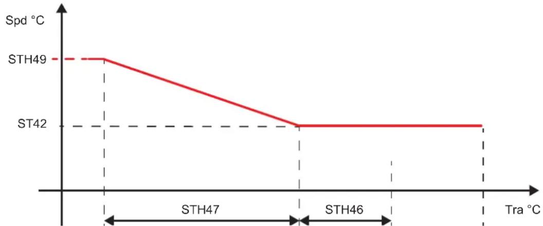
The graph below illustrates cascade control.
line
| Tra °C | Spd °C | | ------ | ------ | | STH49 | 1.0 | | STH46 | 0.0 | | STH47 | 0.0 | | STH42 | 0.0 |Fig. 7 Change of air setpoint in delivery line with "cascade" control in heating mode
In addition to the parameters listed in the table, the abbreviations in the graph are:
- Spd = air setpoint in delivery line;
- Tra = air temperature in return line;
- AOC = automatic mode switching.
If the air temperature in the return line is lower than the difference between the setpoints in parameters "ST42" - "STH46", the value of the air setpoint in the delivery line is increased gradually from the value in parameter "ST42" to the value in parameter "STH49", within the differential set in parameter "STH47".
5.3.3 Disabling heating sources depending on external air temperature
The value of the external air temperature is used as reference to disable the heating sources in the unit. The heating sources are disabled when the temperature is either high or low.
The parameters involved are shown in the table.

The values of the parameters are representative. In specific cases, different values can be set.
Parameter Value UM Description
| STH14 -20.0 °C Mechanical heating - Deactivation threshold for low external air temperature | |
| STH15 30.0 °C Mechanical heating - Deactivation threshold for high external air temperature | |
| STH123 -30.0 °C Auxiliary heating - Deactivation threshold for low external air temperature | |
| STH124 50.0 °C Auxiliary heating - Deactivation threshold for high external air temperature |
Heating generated using the refrigerant circuit is disabled when:
- the external air temperature is low - it drops below the setpoint in parameter "STH14"; heating is enabled again when the temperature value rises above the setpoint in parameter "STH14", plus +1°C;
- the external air temperature is high - it rises above the setpoint in parameter "STH15"; heating is enabled again when the temperature value drops below the setpoint in parameter "STH15", minus +1°C.
Auxiliary heating is disabled when:
- the external air temperature is low - it drops below the setpoint in parameter "STH123".Auxiliary heating is enabled again when the temperature value rises above the setpoint in parameter "STH123", plus +1°C;
- the external air temperature is high - it rises above the setpoint in parameter "STH124". Auxiliary heating is enabled again when the temperature value drops below the setpoint in parameter "STH124", minus +1°C.
5.4 humidity control
Humidity control devices are managed according to the value measured by the reference probe. The measured value is compared with the desired value (setpoint), after which the system calculates the difference between these values and then enables the most suitable devices based on this difference.
The proportional band identifies the control range of the air conditioner system and it is set up with the same values for both humidification and de-humidification.
The dead zone identifies the range around the setpoint within which the devices are not enabled (it is used to prevent oscillations in the setup value).
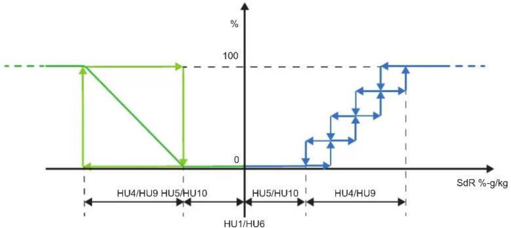
The diagram below shows the behaviour of humidification and de-humidification devices.
line
| SdR %-g/kg | Value (%) | |---|---| | HU4/HU9 | 100 | | HU5/HU10 | 0 | | HU1/HU6 | 0 | | HU5/HU10 | 0 | | HU4/HU9 | 100 | | HU4/HU9 | 100 | | HU4/HU9 | 100 | | HU4/HU9 | 100 | | HU4/HU9 | 100 | | HU4/HU9 | 100 | | HU4/HU9 | 100 | | HU4/HU9 | 100 | | HU4/HU10 | 100 | | HU4/HU10 | 100 | | HU4/HU10 | 100 | | HU4/HU10 | 100 | | HU4/HU10 | 100 | | HU4/HU10 | 100 | | HU4/HU10 | 100 | | HU4/HU10 | -100 | | HU4/HU10 | -100 | | HU4/HU10 | -100 | | HU4/HU10 | -100 | | HU4/HU10 | -100 | | HU4/HU10 | -100 | | HU4/HU10 | -100 | | HU4/HU10 | -125 | | HU4/HU10 | -125 | | HU4/HU10 | -125 | | HU4/HU10 | -125 | | HU4/HU10 | -125 | | HU4/HU10 | -125 | | HU4/HU10 | -125 | | HU4/HU10 | -125 | | | HU4/HU9 | -125 | | HU4/HU9 | -125 | | HU4/HU9 | -125 | | HU4/HU9 | -125 | | HU4/HU9 | -125 | | HU4/HU9 | -125 | | HU4/HU9 | -125 | | HU4/HU9 | -125 | | HU4/HU9 | 37.77 | | HU4/HU9 | 37.77 | | HU4/HU9 | 37.77 | | HU4/HU9 | 37.77 | | HU4/HU9 | 37.77 | | HU4/HU9 | 37.77 | | HU4/HU9 | 37.77 | | HU4/HU9 | -37.77 | | HU4/HU9 | -37.77 | | HU4/HU9 | -37.77 | | HU4/HU9 | -37.77 | | HU4/HU9 | -37.77 | | HU4/HU9 | -37.77 | | HU4/HU9 | -37.77 | | HU8/LH/U6 | 0 | | HU8/LH/U6 | 0 | | HU8/LH/U6 | 0 | | HU8/LH/U6 | 0 | | HU8/LH/U6 | 0 | | HU8/LH/U6 | 0 | | HU8/LH/U6 | 0 | | HU8/LH/U6 | 0 | | HU8/LH/U6 | 0 | | HJ/LH/U6 | 0 | | HJ/LH/U6 | 0 | | HJ/LH/U6 | 0 | | HJ/LH/U6 | 0 | | HJ/LH/U6 | 0 | | HJ/LH/U6 | 0 | | HJ/LH/U6 | 0 | | HJ/LH/U6 | 0 | | HJ/LH/U6 | 0 | | HJ/A-HJ/LH/U6 | 0 | | HJ/A-HJ/LH/U6 | 0 | | HJ/A-HJ/LH/U6 | 0 | | HJ/A-HJ/LH/U6 | 0 | | HJ/A-HJ/LH/U6 | 0 | | HJ/A-HJ/LH/U6 | 0 | | HJ/A-HJ/LH/U6 | 0 | | HJ/A-HJ/U6 | 37.77 | | HJ/A-HJ/U6 | 37.77 | | HJ/A-HJ/U6 | 37.77 | | HJ/A-HJ/U6 | 37.77 | | HJ/A-HJ/U6 | 37.77 | | HJ/A-HJ/U6 | 37.77 | | HJ/A-HJ/U6 | 37.77 | | Hj/A-HJ/U6 | 37.77 | | HJ/A-HJ/U6 | 37.77 | | HJ/A-HJ/U6 | 37.77 | | HJ/A-HJ/U6 | 37.77 | | HJ/A-HJ/U6 | 37.77 | | HJ/A-HJ/U6 | 37.77 | | HJ/A-HJ U6 | 37.77 | | HJ/A-HJ U6 | 37.77 | | HJ/A-HJ U6 | 37.77 | | HJ/A-HJ U6 | 37.77 | | HJ/A-HJ U6 | 37.77 | | HJ/A-HJ U6 | 37.77 | | HJ/A-HJ U6 | 28.88 | | HJ/A-HJ U6 | 28.88 | | HJ/A-HJ U6 | 28.88 | | HJ/A-HJ U6 | 28.88 | | HJ/A-HJ U6 | 28.88 | | HJ/A-HJ U6 | 28.88 | | HJ/A-HJ U6 | 28.88 | | Hj/A-HJ U6 | 28.88 | | Hj/A-HJ U6 | 28.88 | | Hj/A-HJ U6 | 28.88 | | | Hj/A-HJ U6 | 28.88 | | | Hj/A-HJ U6 | 28.88 | | | Hj/A-HJ U6 | 28.88 | | | Hj/A-HJ U6 / SdR %-g/kg | The chart displays the percentage change of SdR (%-g/kg) for two distinct series, one represented by a green line and the other by a blue line, with numerical labels on the y-axis.Fig. 8 Graphical representation of humidity control devices
The parameters involved are shown in the table.
| Parameter Min Max | UM Description | |||
| HU1 HU2 HU3 | % Relative humidity setpoint | |||
| HU4 0.0 25.0 % | Relative humidity control differential | |||
| HU5 0.0 10.0 % | Relative humidity control neutral area | |||
| HU6 HU7 HU8 | g/kg Absolute humidity setpoint | |||
| HU9 0.0 10.0 g/kg Absolute humidity control differential | ||||
| HU10 0.0 10.0 g/kg Absolute humidity control neutral area | ||||
| HU11 0 | 1 | - | Humidity value control type | |
The value set in parameter "HU11" identifies the reference humidity value, as follows:
- 0 = relative humidity;
- 1 = absolute humidity.
5.4.1 Relative humidity control with proportional control
If parameter "HU11" is set to "0", humidity control is performed according to the relative humidity value.
Relative humidity is managed according to parameter "HU14", which identifies the probe on which the controller must guarantee maintenance of the entered setpoint, and on parameter "HU12" that determines the type of humidity control.
The parameters involved are shown in the table.

The values of the parameters are representative. In specific cases, different values can be set.
Parameter Value UM Description
HU4 5.0 % Relative humidity control differential
HU5 0.5 % Relative humidity control neutral area
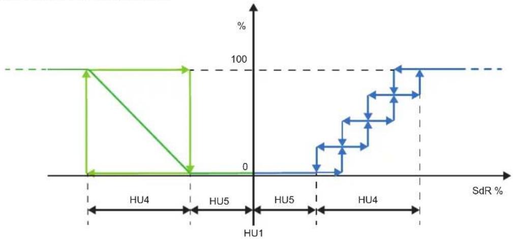
A graphical representation is shown below.
line
| SdR (%) | Value (%) | |---|---| | HU4 | 100 | | HU5 | 0 | | HU1 | 0 | | HU5 | 0 | | HU4 | 100 | | HU4 | 20 | | HU4 | 30 | | HU4 | 40 | | HU4 | 50 | | HU4 | 60 | | HU4 | 70 | | HU4 | 80 | | HU4 | 90 | | HU4 | 100 | | HU4 | -100 | | HU4 | -200 | | HU4 | -300 | | HU4 | -400 | | HU4 | -500 | | HU4 | -600 | | HU4 | -700 | | HU4 | -800 | | HU4 | -900 | | HU4 | -1000 | | HU4 | -1100 | | HU4 | -1200 | | HU4 | -1300 | | HU4 | -1400 | | HU4 | -1500 | | HU4 | -1600 | | HU4 | -1700 | | HU4 | -1800 | | HU4 | -1900 | | HU4 | -2000 | | HU4 | -2100 | | HU4 | -2200 | | HU4 | -2300 | | HU4 | -2400 | | HU4 | -2500 | | HU4 | -2600 | | HU4 | -2700 | | HU4 | -2800 | | HU4 | -2900 | | HU4 | -3000 | | HU4 | -3100 | | HU4 | -3200 | | HU4 | -3300 | | HU4 | -3400 | | HU4 | -3500 | | HU4 | -3600 | | HU4 | -3700 | | HU4 | -3800 | | HU4 | -3900 | | HU4 | -4000 | | HU4 | -4100 | | HU4 | -4200 | | HU4 | -4300 | | HU4 | -4400 | | HU4 | -4500 | | HU4 | -4600 | | HU4 | -4700 | | HU4 | -4800 | | HU4 | -4900 | | HU4 | -5000 | | HU4 | -5100 | | HU4 | -5200 | | HU4 | -5300 | | HU4 | -5400 | | HU4 | -5500 | | HU4 | -5600 | | HU4 | -5700 | | HU4 | -5800 | | HU4 | -5900 | | HU4 | -6000 | | HU4 | -6100 | | HU4 | -6200 | | HU4 | -6300 | | HU4 | -6400 | | HU4 | -6500 | | HU4 | -6600 | | HU4 | -6700 | | HU4 | -6800 | | HU4 | -6900 | | HU4 | -7000 | | HU4 | -7100 | | HU4 | -7200 | | HU4 | -7300 | | HU4 | -7400 | | HU4 | -7500 | | HU4 | -7600 | | HU4 | -7700 | | HU4 | -7800 | | HU4 | -7900 | | HU4 | -8000 | | HU4 | -8100 | | HU4 | -8200 | | HU4 | -8300 | | HU4 | -8400 | | HU4 | -8500 | | HU4 | -8600 | | HU4 | -8700 | | HU4 | -8800 | | HU4 | -8900 | | HU4 | -9000 | | HU1 | 15.5% (approx) | | UH1 (approx) | 15.5% (approx) | | UH2 (approx) | 15.5% (approx) | | UH3 (approx) | 15.5% (approx) | | UH1 (approx) | 15.5% (approx) | | UH2 (approx) | 15.5% (approx) | | UH3 (approx) | 15.5% (approx) | | UH1 (approx) | 15.5% (approx) | | UH2 (approx) | 15.5% (approx) |Fig. 9 Relative humidity control
5.5 Air humidification
The controller can manage air humidification using a built-in humidifier in the unit.
The controller is set up at the factory with all the parameters required to control the installed humidifier.
5.5.1 Ancillary built-in humidifier functions
Humidifier control includes some ancillary functions, a description of which is given below.
5.5.1.1 Manual water drain
The manual water drain function is designed to fully empty the cylinder in the humidifier. This function is enabled only through the web page. Access to this page requires the operator to log in with a Service level password. If the humidifier is producing steam, enabling of the function causes steam production to be stopped instantly.
5.5.1.2 Pre-washing
The pre-washing function is used to wash the water lines and the humidifier cylinder. The cylinder is filled and then emptied 3 times in order to wash away impurities from the pipes and cylinder, if any. We recommend enabling this function especially after connecting the water lines or after cylinder replacement. This function is enabled only through the web page. Access to this page requires the operator to log in with a Service level password. If the humidifier is producing steam, enabling of the function causes steam production to be stopped instantly.
5.5.1.3 Water drainage before machine shutdown
The function for water drainage before a machine shutdown is enabled in order to avoid water stagnation in the humidifier cylinder, which may lead to the formation of algae or bacteria (e.g. Legionella), if the cylinder is filled with water for over 72 consecutive hours without producing steam. The cylinder is drained and remains as such until it receives a signal requesting the production of steam. The function is always active and the shutdown interval is fixed.
5.6 Air dehumidification
Air dehumidification is required during the cooling cycle, where it occurs naturally.
If dehumidification is required simultaneously with cooling, the controller starts the compressors, based on which of the two demands is greater.
The possibility exists that the temperature setpoint is reached before the humidity setpoint is achieved. If this is the case, the controller pushes cooling even further so as to cause the temperature to drop below the setpoint.
However, to prevent an excessive drop of the air temperature in the room, the controller uses the heating devices fitted in the unit to post-heat the air.
5.7 Power supply control
Units may be supplied with devices for protection against incorrect connections of the phase sequence or voltage variations outside the required limits during operation.
Protections consist in relays which output an alarm signal to one digital input in the controller through an electric contact (the digital input concerned is shown in the wiring diagram).
The unit can be fitted with one relay to monitor correct phase sequence or one relay to monitor the power voltage or one relay to manage both these functions.
5.7.1 Phase sequence
A dedicated relay is fitted to manage incorrect connection of the phase sequence to the unit. If the phase sequence is connected incorrectly, the relay opens an electric contact that triggers alarm "AL55" on the controller display.
Incorrect connection of the phase sequence may be experienced upon unit installation or when work is performed on the power supply line.
Power must be cut out to the unit to make the connection correctly. The alarm is cleared as soon as the unit is switched on again.
5.7.2 Min. / Max. voltage
The controller is designed to manage potential conditions where the variation of the power voltage to the unit experiences a significant deviation from the expected values.
5.7.3 Fast Restart
Activation of the “Fast Restart” function, provided that an “ultracap” is fitted to keep the controller electrically powered, is designed to minimise as much as possible the delay experienced in restarting the compressors fitted in the unit.
This is possible because the controller starts counting the minimum time to OFF as soon as a switch-off is started due to a blackout.
The controller detects problems with the main power supply through a digital input and manages them as alarms.
To protect the integrity of the compressors, the controller manages the maximum number of starts per hour by means of the delay between two consecutive starts.
Quick restart after a blackout depends on the thermoregulation demand. It requires a demand for cooling or dehumidification and the off-set for the activation of at least one compressor.
The “Fast Restart” function does not jeopardise the conditions of the compressors as it limits the number of quick starts over the space of an hour or a day.
5.8 Damper management
In addition to air change in the room, the controller can also manage other functions connected to comfort enhancement and system economy.
The functions the controller can handle vary according to the number of dampers fitted in the unit:
- units with 2 dampers, for fresh air only;
- units with 3 dampers, when free cooling / free heating is featured;
- units with 4 dampers, when a heat recovery system is fitted in addition to free cooling / free heating.
Dampers can be set either linearly or proportionally.
Units with two dampers
The dampers featured in 2-damper units include: a damper for fresh external air and a damper for recirculated air. Normally, their operation is complementary, i.e. the percentage opening of the external air damper is equal to the percentage closing of the recycled air damper.
Units with three dampers
The dampers featured in 3-damper units include: a damper for fresh air, a damper for exhaust air and a damper for recirculated air.
Normally, the external air damper opens at the same percentage as the exhaust air damper and the recycled air damper is complementary to the other two. So, the percentage opening of the external air damper and the exhaust air damper is equal to the percentage closing of the recycled air damper.
Units with four dampers
Units with four dampers feature the same dampers as 3-damper units plus one. The fourth damper is used for external air.
It is used to cause the external air to flow through the heat recovery system, when heat recovery is enabled, and it is closed in free cooling mode.
If the heat recovery system is not sized to provide for a 100% air flow in the unit, a fifth damper is actually fitted. This is an extra exhaust damper that is used by the unit in free cooling mode to bypass the heat recovery system.
The parameters involved are shown in the table.
| Parameter Min Max | UM Description | |||
| DA43 0.0 50.0 | °C | External air - Opening reduction for external air temperature - Summer temperature threshold | ||
| DA44 -20.0 16 | 0 °C | External air - Opening reduction for external air temperature - Winter temperature threshold | ||
| DA45 0 100 % | External air - Opening reduction for external air temperature - Min opening | |||
| DA52 0 3 - | External air - Start up - Configuration | |||
| DA54 0 999 min | External air - Start up - Wash duration | |||
5.8.1 Damper control
The controller can control the dampers in two different ways: "standard" and "adaptive".
When dampers are required to stay in a fixed position, for instance to provide for the correct flow of fresh air, system conditions may exist in which the damper signal cannot guarantee the desired air percentage.
5.8.1.1 Standard control
Standard control requires that the dampers stay in their position irrespective of the actual fresh air percentage.
5.8.1.2 Adaptive control
Adaptive control corrects damper opening based on the necessary fresh air percentage. This control requires that the mixed air probe is fitted.
The controller uses the values of the air temperature in the return line, the external air temperature and the corresponding damper opening percentage to calculate the theoretical value of mixed air.
The controller compares the calculated mixed air value with the value actually measured and then uses a PID to correct the damper signal until the difference is cancelled.
5.8.2 Damper management
The controller can manage damper control either linearly or proportionally.
Linear control enables opening of the damper with a tilt angle that is equal to the required opening percentage.
Proportional control is designed to open the dampers so that the air can flow, i.e. at the required percentage of the max. possible opening.

All units featuring dampers are set by default to run a proportional control.
5.8.3 Unit start-up
When the unit is started up, specific damper adjustments may be required for some management functions.
If no washing or recycling cycle is to be run at unit start-up, the controller opens the dampers at the percentage value set for air changing, irrespective of their number.
5.8.4 Washing
Washing means changing the air in the room and it consists in exhausting all the air in the return line and only letting external air flow into the room.
If washing is required at unit start-up, parameter "DA52" must be set to "1".
While the washing cycle is in progress, the controller keeps the exhaust air and external air dampers open at their max. opening percentage and it keeps the recycled air damper in closed position for the time setpoint in parameter "DA54".
If the value in parameter “DA53” is set to “0”, the washing cycle takes place without any thermoregulation of the air. If the value in parameter “DA53” is set to “1”, thermoregulation is active.
If the washing cycle is run with thermoregulation active, the position of the dampers may be affected by conditions resulting from compressor operation.
While the washing cycle is in progress, a button flashes on the main screen: it is pressed to stop the cycle manually before the time set in parameter "DA54" elapses.
5.8.5 Recirculation
Full air recycling at system start-up or after a washing cycle is intended to achieve the temperature and humidity setpoints more quickly.
If air recycling only is required at unit start-up, parameter "DA52" must be set to "2".
If parameter "DA52" is set to "3", a washing cycle is performed before recycling.
While recycling is in progress, the controller keeps the exhaust air and external air dampers closed and it keeps the recycled air damper open for the time setpoint stored in parameter "DA55".
If the value in parameter “DA53” is set to “0”, the washing cycle takes place without any thermoregulation of the air. If the value in parameter “DA53” is set to “1”, thermoregulation is active.
While recycling is in progress, a button flashes on the main screen which is pressed to stop the cycle manually before the time set in parameter "DA55" elapses.
5.9 Auxiliary heating
In addition to the heating effect achieved using the refrigerant circuit, the controller can handle other sources of heating such as electric heaters and a hot water coil with an OK signal to a boiler or a burner.
The logic featured in the controller is set up at the factory, based on the unit configuration.
The function to enable heating and the operating logics can be customised.
The parameters concerned are shown in the table.
| Parameter Min Max | UM Description | |
| STH57 0 1 - Auxiliary heating - Summer oper. - Type of temperature control | ||
| STH58 10.0 35.0 °C Auxiliary heating - Summer oper. - Setpoint | ||
| STH59 0.0 25.0 °C Auxiliary heating - Summer oper. - Proportional - Temperature offset | ||
| STH60 0.0 25.0 °C Auxiliary heating - Summer oper. - Proportional - Activation differential | ||
| STH61 0 100 % Auxiliary heating - Summer oper. - Proportional - Minimum request | ||
| STH62 0 100 % Auxiliary heating - Summer oper. - Proportional - Maximum request | ||
| STH91 0 1 - Auxiliary heating - Winter oper. - Type of temperature control | ||
| STH93 0.0 25.0 °C Auxiliary heating - Winter oper. - Proportional - Temperature offset | ||
| STH94 0.0 25.0 °C Auxiliary heating - Winter oper. - Proportional - Activation differential | ||
| STH95 0 100 % Auxiliary heating - Winter oper. - Proportional - Minimum request | ||
| STH96 0 100 % Auxiliary heating - Winter oper. - Proportional - Maximum request | ||
5.9.1 Controlled devices
The controller controls the devices installed in the unit, which may include:
- electrical heaters, divided by either one or two power steps;
- a hot water coil, with an analogue signal to control opening of a valve and a digital OK signal to control a pump that gets started as soon as the valve opens. This management logic includes the anti-freeze function;
- a boiler that is controlled by an analogue signal and a digital OK signal which gets enabled as soon as an analogue demand is received. This management logic includes a digital input through which the controller receives alarms from the boiler, if any, as well as an anti-freeze function;
- a burner that is controlled by an analogue signal and a digital OK signal which gets enabled as soon as an analogue demand is received. This management logic includes a digital input through which the controller receives alarms from the burner, if any.
Parameter "STH55" is used to enable auxiliary heating for:
- summer operation only, in which case it serves as post heating during the dehumidification cycle;
- winter operation only, in which case it serves either as single source, if the refrigerant circuit does not feature cycle reversal, or as an integration to heating where the latter is implemented by the refrigerant circuit;
- both summer and winter operation.
Anti-freeze function
The anti-freeze function, which is included in versions featuring a hot water coil and a boiler, is enabled when the unit is in operation, no heating demand is present and the external air temperature is lower than the setpoint in parameter "STH136".
In versions with a hot water coil, when the anti-freeze function gets enabled, the controller opens the relevant control valve at the value set in parameter "STH137" and it enables the circulation pump.
In versions with a boiler, when the anti-freeze function gets enabled, the controller outputs to the boiler the demand signal as set in parameter "STH137" and an OK signal for activation.
5.9.2 Post heating
When the value in parameter "STH55" is "1", auxiliary heating is configured for summer operation only and serves as post heating during dehumidification. The control can either be proportional or PID, depending on the value set in parameter "STH57". The value in parameter "STH56" identifies the probe taken as reference for the control which is performed according to parameter "STH58".
5.9.3 Activation according to time bands
The unit may be managed automatically according to time bands. The time band management logic is designed to stop the unit, to edit the setpoint and to switch among operating modes.
The parameters concerned are shown in the table.
| Parameter Min Max | UM Description | |
| ES1 0 144 h Time band | 1 - Start | |
| ES2 0 144 h Time band | 1 - End | |
| ES3 0 144 h Time band | 2 - Start | |
| ES4 0 144 h Time band | 2 - End | |
| ES5 0 144 h Time band | 3 - Start | |
| ES6 0 144 h Time band | 3 - End | |
| ES7 0 15 - Setpoint variation - Monday | ||
| ES8 0 15 - Setpoint variation - Tuesday | ||
| ES9 0 15 - Setpoint variation - Wednesday | ||
| ES10 0 15 - Setpoint variation - Thursday | ||
| ES11 0 15 - Setpoint variation - Friday | ||
| ES12 0 15 - Setpoint variation - Saturday | ||
| ES13 0 15 - Setpoint variation - Sunday | ||
| ES14 -25.0 25 | 0 °C Setpoint variation - Mechanical cooling - Offset | |
| ES16 -25.0 25 | 0 °C Setpoint variation - Mechanical heating - Offset | |
| ES18 0 15 - Unit switch-off - Monday | ||
| ES19 0 15 - Unit switch-off - Tuesday | ||
| ES20 0 15 - Unit switch-off - Wednesday | ||
| ES21 0 15 - Unit switch-off - Thursday | ||
| ES22 0 15 - Unit switch-off - Friday | ||
| ES23 0 15 - Unit switch-off - Saturday | ||
| ES24 0 15 - Unit switch-off - Sunday | ||
| ES26 0 144 h Time band | 4 - Start | |
| ES27 0 144 h Time band | 4 - End | |
| ES31 0 15 - Heating mode activation - Monday | ||
| ES32 0 15 - Heating mode activation - Tuesday | ||
| ES33 0 15 - Heating mode activation - Wednesday | ||
| ES34 0 15 - Heating mode activation - Thursday | ||
| ES35 0 15 - Heating mode activation - Friday | ||
| ES36 0 15 - Heating mode activation - Saturday | ||
| ES37 0 15 - Heating mode activation - Sunday | ||
The pairs of start and end parameters are used to set as many as 4 time bands.
Each day of the week can be matched with a combination of the set time bands in order to edit the setpoint, switch the unit off and switch between operating modes.
The setpoint is edited within the selected time band by way of applying an offset to the active operating value.
The active operating value is given by the value set in the relevant parameter and external offsets, if any.
The offset value can be either positive or negative. When it is positive, it is added; when it is negative, it is subtracted.
Two offset values can be set: one for operation in cooling mode and one in heating mode.

If the controller manages auxiliary heating, the setpoint in parameter "STH58" is maintained when the time bands are activated in cooling mode; when they are activated in heating mode, the setpoint varies according to the offset value.
5.1 Introduction
The controller is programmed to manage the components of the unit safely, by adjusting their operation as conditions change with the aim of maintaining uninterrupted service.
Within the scope of this control function, the controller will partially or completely limit operation of the unit when hazardous conditions are approaching.

A click on this icon gives access to the Alarms menu. If the icon is red, at least one alarm is active; no alarm is active if it is grey.
The codes with their descriptions for the various conditions that can appear in the alarm menu are given in the next chapter.
If you notice there are error messages with the unit running and with it stopped, you should promptly inform the customer support centre and given them the code and the message description and wait for their instructions.

Do not take initiatives before consulting the customer support centre.
5.2 Alarm table
A list of alarm codes with their descriptions is given below.
| Code Description Code Description | |||
| AL1 Internal memory error alarm AL29 Low temperature alarm of return air | |||
| AL5 | Air flow alarm from differential pressure transducer | AL30 High temperature alarm of supply air | |
| AL6 | Circuit 1 - High pressure alarm from pressure switch | AL31 Low temperature alarm of supply air | |
| AL7 | Circuit 2 - High pressure alarm from pressure switch | AL32 Temperature limitation activated of supply air | |
| AL10 | Circuit 1 - High pressure alarm from transducer | AL33 | Circuit 1 - External ventilation - Thermal overload alarm |
| AL11 | Circuit 2 - High pressure alarm from transducer | AL34 | Circuit 2 - External ventilation - Thermal overload alarm |
| AL12 High humidity alarm of return air AL35 Supply ventilation - Thermal overload alarm | |||
| AL13 Low humidity alarm of return air AL36 Return ventilation - Thermal overload alarm | |||
| AL14 Dirty filters alarm AL51 Circuit 1 - Compressor 1 - Inverter tripped | |||
| AL17 BMS - Communication error alarm AL52 c.pCOe 1 - Communication error alarm | |||
| AL18 | Circuit 1 - Compressor 1 - Thermal overload alarm | AL53 c.p COe 2 - Communication error alarm | |
| AL19 | Circuit 1 - Compressor 2 - Thermal overload alarm | AL54 c.p COe 3 - Communication error alarm | |
| AL20 | Circuit 2 - Compressor 1 - Thermal overload alarm | AL55 Incorrect phase sequence alarm | |
| AL21 | Circuit 2 - Compressor 2 - Thermal overload alarm | AL57 | Circuit 1 - Compressor 1 - High discharge temperature alarm |
| AL26 Temperature limitation activated of return air AL58 | Circuit 2 - Compressor 1 - High discharge temperature alarm | ||
| AL27 Low temperature alarm of external air AL59 | Circuit 1 - Compressor 2 - High discharge temperature alarm | ||
| AL28 High temperature alarm of return air AL60 | Circuit 2 - Compressor 2 - High discharge temperature alarm | ||
| Code | Description Code Description | ||
| AL61 | Probe error alarm - Circuit 1 - Compressor 1 - Discharge temperature | AL136 | Circuit 1 - Low pressure alarm from pressure switch |
| AL62 | Probe error alarm - Circuit 2 - Compressor 1 - Discharge temperature | AL137 | Circuit 2 - Low pressure alarm from pressure switch |
| AL63 | Probe error alarm - Circuit 1 - Compressor 2 - Discharge temperature | AL154 Leak detector alarm | |
| AL64 | Probe error alarm - Circuit 2 - Compressor 2 - Discharge temperature | AL159 Fire / smoke alarm | |
| AL65 | Probe error alarm - Return air temperature AL160 Valve driver 1 - Communication error alarm | ||
| AL70 | Probe error alarm - Supply air temperature AL161 Valve driver 2 - Communication error alarm | ||
| AL72 | Transducer error alarm - Return air differential pressure | AL162 CPY humidifier - Generic alarm | |
| AL73 | Transducer error alarm - Static pressure of return channel / Aisle differential pressure | AL163 CPY humidifier - Generic warning | |
| AL74 | Probe error alarm - CO2 air quality AL164 CPY humidifier - Communication error alarm | ||
| AL75 | Probe error alarm - VOC air quality AL166 Inverter 1 - Communication error alarm | ||
| AL78 | Probe error alarm - Return air relative humidity AL170 Circuit 1 - Low superheat alarm | ||
| AL79 | Probe error alarm - External air relative humidity | AL171 Circuit 2 - Low superheat alarm | |
| AL80 | Probe error alarm - External air temperature AL183 Cooling setpoint lower than heating setpoint | ||
| AL91 | Probe error alarm - Mixed air temperature AL184 Circuit 1 - Defrost ended for maximum time | ||
| AL94 | Transducer error alarm - Circuit 1 - Condensing pressure | AL185 Circuit 2 - Defrost ended for maximum time | |
| AL95 | Transducer error alarm - Circuit 2 - Condensing pressure | AL191 Max. number of fast starts in 1 hour achieved | |
| AL98 | Transducer error alarm - Circuit 1 - Evaporating pressure | AL192 Max. number of fast starts in 24 hours achieved | |
| AL99 | Transducer error alarm - Circuit 2 - Evaporating pressure | AL201 Min / Max voltage | |
| AL102 | Probe error alarm - Circuit 1 - Suction temperature | AL203 Circuit 1 - Low evaporating pressure | |
| AL103 | Probe error alarm - Circuit 2 - Suction temperature | AL204 Circuit 2 - Low evaporating pressure | |
| AL106 | Transducer error alarm - Supply air differential pressure | AL209 External alarm | |
| AL107 | Transducer error alarm - Static pressure of supply channel / Aisle differential pressure | AL210 EEPROM error alarm | |
| AL114 C | Circuit 1 - Low pressure difference AL212 Alarm: access error to internal memory | ||
| AL115 C | Circuit 2 - Low pressure difference AL247 Circuit 1 - Compressor 1 - Out of envelope | ||
| AL127 C | Circuit 1 - Compressor 1 - Maintenance alarm AL250 Heater 1 - Thermal overload alarm | ||
| AL128 C | Circuit 1 - Compressor 2 - Maintenance alarm AL251 Heater 2 - Thermal overload alarm | ||
| AL131 C | Circuit 2 - Compressor 1 - Maintenance alarm AL258 Boiler - Generic alarm | ||
| AL132 C | Circuit 2 - Compressor 2 - Maintenance alarm AL259 Burner - Generic alarm | ||
| AL135 S | Supply ventilation - Maintenance alarm - | ||
Inhaltsverzeichnis
6 Einleitung 40
6.1 Allgemeines 40
line
| Stages | Value | | ------ | ----- | | STH1 | 100 | | STH2 | 0 | | STH3 | 0 | | STH4 | 100 |line
| SdR (°C) | Value (%) | |---|---| | ST1 | 0 | | ST5 | 0 | | ST6 | 0 | | ST4 | 20 | | ST4 | 30 | | ST4 | 40 | | ST4 | 50 | | ST4 | 60 | | ST4 | 70 | | ST4 | 80 | | ST4 | 90 | | ST4 | 100 | | ST5 | 100 | | ST6 | 100 |line
| Tra °C | Spd °C | |---|---| | AOC | ST42 | | ST42 | ST42 | | ST43 | ST42 | | ST44 | ST45 | | Tra | ST45 |line
| Stages | Value | | ------ | ----- | | STH6 | 100 | | STH5 | 0 | | STH1 | 0 | | ST1 | 0 | | ST5 | 0 | | ST6 | 0 | | ST4 | 100 |line
| Tra °C | Spd °C | |---|---| | AOC | ST42 | | ST42 | ST42 | | ST43 | ST42 | | ST44 | ST45 | | End | ST45 |- Setpoint
* Unit
* Ventilation
* Humidification Dehumidification
* Dampers
* Auxiliary heating
* Post-heating gas
* Environment air renewal - Probes
- I/O
* Universal inputs
* Digital inputs
* Driver 1
* Analog outputs
* Digital outputs
* Driver 2 - Language
* English
* Italian
* Swedish
* German
* French
* Spanish
* Polish - Alarm history
- Charts
- Login
- Configuration
* Date hour
* Backlight
* Network
* HMI
* Led
* Font - Parameters
* ST - Mechanical cooling
* STH - Mechanical heating
* SFA - Temperature control ventilation
* SP - Setup
* FA - Supply ventilation
* RFA - Return ventilation
* PAL - Alarms
* CF - Configuration
* CO - Compressors
* ET - Electronic thermostatic valve
* PID - PID parameters
* ES - Energy Saving
* UN - Unloading
* DF - Defrost
* HU - Humidity
* PD - Pump Down
* SD - Dynamic setpoint
* DA - Dampers
* EFA - External ventilation
* CA - Calibration probes
* RA - Transducer probe full scale
* ENV - Envelope - Files management
* Saving timelog.txt
* Upload default.conf
* Upload alarm.conf
line
| Temperature Range | Condition | | ----------------- | ------------- | | 0 | ST1 + SD12 | | 30 | ST1 | | 30 | ST1 - SD12 | | 30 | SD12 > 0 | | 30 | SD12 < 0 |line
| Temperature Range | Label | | ----------------- | ------------- | | 0 - SD21 | STH1 + SD22 | | 0 - SD21 | STH1 | | 0 - SD21 | STH1 - SD22 | | 0 - SD20 | STH1 - SD22 | | 0 - SD20 | STH1 + SD22 | | 0 - SD20 | STH1 | | 0 - SD20 | STH1 - SD22 | | 0 - SD20 | STH1 + SD22 | | 0 - SD20 | STH1 | | 0 - SD20 | STH1 - SD22 | | 0 - SD20 | STH1 + SD22 | | 0 - SD20 | STH1 | | 0 - SD20 | STH1 - SD22 | | 0 - SD20 | STH1 + SD22 | | 0 - SD20 | STH1 | | 0 - SD20 | STH1 - SD22 | | 0 - SD20 | STH1 + SD22 | | 0 - SD20 | STH13 | | 0 - SD20 | STH13 | | 0 - SD20 | STH13 | | 0 - SD20 | STH13 | | 0 - SD20 | STH13 | | 0 - SD20 | STH13 | | 0 - SD20 | STH13 | | 0 - SD20 | | 0 - SD20 | STH13 | | 0 - SD20 | STH13 | | 0 - SD20 | STH13 | | 0 - SD20 | STH13 | | 0 - SD20 | STH13 | | 0 - SD20 | STH13 | | 0 - SD20 (Right) | STH1 + SD22 | | 0 - SD20 | STH13 | | 0 - SD20 | STH13 | | 0 - SD20 | STH13 | | 0 - SD20 | STH13 | | 0 - SD20 | STH13 | | 0 - SD20 | STH13 |line
| SdR °C | Value (%) | | ------ | --------- | | STH1 | 100 | | STH5 | 0 | | STH6 | 0 | | ST1 | 0 | | ST5 | 0 | | ST6 | 0 | | ST4 | 100 |- 0 = proportioneel;
- 1 = "Cascade";
- 2 = PID.
line
| Tra °C | Spd °C | |---|---| | AOC | ST42 | | ST42 | ST42 | | ST43 | ST42 | | ST44 | ST45 | | Tra | ST45 |* ES - Energy saving
* Un - Unloading
* DF - Descongelar
* HU - Humedad
* PD - Pump down
line
| Temperature Range | Label | | ----------------- | ------------- | | 0 - SD21 | STH1 + SD22 | | 0 - SD21 | STH1 | | 0 - SD21 | STH1 - SD22 | | 0 - SD20 | STH1 - SD22 | | 0 - SD20 | STH1 + SD22 | | 0 - SD20 | STH1 | | 0 - SD20 | STH1 - SD22 | | 0 - SD20 | STH1 + SD22 | | 0 - SD20 | STH1 | | 0 - SD20 | STH1 - SD22 | | 0 - SD20 | STH1 + SD22 | | 0 - SD20 | STH1 | | 0 - SD20 | STH1 - SD22 | | 0 - SD20 | STH1 + SD22 | | 0 - SD20 | STH1 | | 0 - SD20 | STH1 - SD22 | | 0 - SD20 | STH1 + SD22 | | 0 - SD20 | STH13 | | 0 - SD20 | STH13 | | 0 - SD20 | STH13 | | 0 - SD20 | STH13 | | 0 - SD20 | STH13 | | 0 - SD20 | STH13 | | 0 - SD20 | STH13 | | 0 - SD20 | | 0 - SD20 | STH13 | | 0 - SD20 | STH13 | | 0 - SD20 | STH13 | | 0 - SD20 | STH13 | | 0 - SD20 | STH13 | | 0 - SD20 | STH13 | | 0 - SD20 (Bottom) | STH1 + SD22 | | 0 - SD20 | STH13 | | 0 - SD20 | STH13 | | 0 - SD20 | STH13 | | 0 - SD20 | STH13 | | 0 - SD20 | STH13 | | 0 - SD20 | STH13 |line
| Stages | Value | | ------ | ----- | | STH6 | 100 | | STH5 | 0 | | STH1 | 0 | | ST1 | 0 | | ST5 | 0 | | ST6 | 0 | | ST4 | 100 |line
| Tra °C | Spd °C | |---|---| | AOC | ST42 | | ST42 | ST42 | | ST43 | ST42 | | ST44 | ST45 | | End | ST45 |line
| Tra °C | Spd °C | | ------ | ------ | | STH49 | 1.0 | | STH42 | 1.0 | | STH46 | 1.0 |line
| Stages | Value | | ------ | ----- | | STH1 | 100 | | STH2 | 0 | | STH3 | 0 | | STH4 | 100 |line
| SdR °C | Value (%) | | ------ | --------- | | SdR | 100 | | STH1 | 0 | | STH5 | 0 | | STH6 | 0 | | STH4 | 0 |- Setpoint
* Unit
* Ventilation
* Humidification Dehumidification
* Dampers
* Auxiliary heating
* Post-heating g
* Environment air renewal - Probes
-1/0
* Universal inputs
* Digital inputs
* Driver 1
* Analog outputs
* Digital outputs
* Driver 2 - Language
* English
* Italian
* Swedish
* German
* French
* Spanish
* Polish - Alarm history
- Charts
- Login
- Configuration
* Date hour
* Backlight
* Network
* HMI
* Led
* Font - Parameters
* ST - Mechanical cooling
* STH - Mechanical heating
* SFA - Temperature control ventilation
* SP - Setup
* FA - Supply ventilation
* RFA - Return ventilation
* PAL - Alarms
* CF - Configuration
* CO - Compressors
* ET - Electronic thermostatic valve
* PID - PID parameters
* ES - Energy Saving
* UN - Unloading
* DF - Defrost
* HU - Humidity
* PD - Pump Down
* SD - Dynamic setpoint
* DA - Dampers
* EFA - External ventilation
* CA - Calibration probes
* RA - Transducer probe full scale
* ENV - Envelope - Files management
* Saving timelog.txt
* Upload default.conf
* Upload alarm.conf
other
| Stage | Value (%) | |---|---| | Bar 1 | 9.13 | | Bar 2 | 7.6 | | Bar 3 | 99.9 | | Bar 4 | 25.48 | | Bar 5 | 44.1 | | Bar 6 | 68.4 | | Steps | 80.6 | | Sh 4.9 °C | 100 | | Sh 4.9 °C | 45.8 | Circuit 1 indicates a warning or alert condition.line
| Text °C | Value | | ------- | ----- | | ST1 | 0 | | ST1 + SD12 | 0 | | ST1 - SD12 | 0 | | SD12 > 0 | 0 | | SD12 < 0 | 0 | | SD10 | 0 |line
| SdR °C | Value (%) | | ------ | --------- | | 0 | 100 | | STH6 | 0 | | STH4 | 0 | | STH5 | 0 | | STH1 | 0 | | ST1 | 0 | | ST5 | 0 | | ST6 | 0 | | ST4 | 100 |- Setpoint
* Unit
* Ventilation
* Humidification Dehumidification
* Dampers
* Auxiliary heating
* Post-heating gas
* Environment air renewal - Probes
-1/0
* Universal inputs
* Digital inputs
* Driver 1
* Analog outputs
* Digital outputs
* Driver 2 - Language
* English
* Italian
* Swedish
* German
* French
* Spanish
* Polish - Alarm history
- Charts
- Login
- Configuration
* Date hour
* Backlight
* Network
* HMI
* Led
* Font - Parameters
* ST - Mechanical cooling
* STH - Mechanical heating
* SFA - Temperature control ventilation
* SP - Setup
* FA - Supply ventilation
* RFA - Return ventilation
* PAL - Alarms
* CF - Configuration
* CO - Compressors
* ET - Electronic thermostatic valve
* PID - PID parameters
* ES - Energy Saving
* UN - Unloading
* DF - Defrost
* HU - Humidity
* PD - Pump Down
* SD - Dynamic setpoint
* DA - Dampers
* EFA - External ventilation
* CA - Calibration probes
* RA - Transducer probe full scale
* ENV - Envelope - Files management
* Saving timelog.txt
* Upload default.conf
* Upload alarm.conf
39.1.1 O menu das máscaras
line
| SdR °C | Value (%) | | ------ | --------- | | 0 | 100 | | STH6 | 0 | | STH4 | 0 | | STH5 | 0 | | STH1 | 0 | | ST1 | 0 | | ST5 | 0 | | ST6 | 0 | | ST4 | 100 |line
| Tra °C | Spd °C | |---|---| | AOC | ST42 | | ST42 | ST42 | | ST43 | ST42 | | ST44 | ST45 | | Tra | ST45 |line
| Tra °C | Spd °C | | ------ | ------ | | STH49 | 1.0 | | STH46 | 0.0 | | STH47 | 0.0 | | STH42 | 0.0 |- Setpoint
* Unit
* Ventilation
* Humidification Dehumidification
* Dampers
* Auxiliary heating
* Post-heating g
* Environment air renewal - Probes
- 1/0
* Universal inputs
* Digital inputs
* Driver 1
* Analog outputs
* Digital outputs
* Driver 2 - Language
* English
* Italian
* Swedish
* German
* French
* Spanish
* Polish - Alarm history
- Charts
- Login
- Configuration
* Date hour
* Backlight
* Network
* HMI
* Led
* Font - Parameters
* ST - Mechanical cooling
* STH - Mechanical heating
* SFA - Temperature control ventilation
* SP - Setup
* FA - Supply ventilation
* RFA - Return ventilation
* PAL - Alarms
* CF - Configuration
* CO - Compressors
* ET - Electronic thermostatic valve
* PID - PID parameters
* ES - Energy Saving
* UN - Unloading
* DF - Defrost
* HU - Humidity
* PD - Pump Down
* SD - Dynamic setpoint
* DA - Dampers
* EFA - External ventilation
* CA - Calibration probes
* RA - Transducer probe full scale
* ENV - Envelope - Files management
* Saving timelog.txt
* Upload default.conf
* Upload alarm.conf
other
| Stage | Value (%) | |---|---| | Bar 1 | 9.13 | | Bar 2 | 7.6 | | Bar 3 | 99.9 | | Bar 4 | 25.48 | | Bar 5 | 44.1 | | Bar 6 | 68.4 | | Step 1 | 80.6 | | Steps 1 | 387 | | Sh 4.9 °C | 100 | | Sh 4.9 °C | 45.8 | Circuit 1 warning icon indicates 'C' to denote 'C'.line
| SdR °C | Value (%) | | ------ | --------- | | STH6 | 100 | | STH5 | 0 | | STH1 | 0 | | ST1 | 0 | | ST5 | 0 | | ST6 | 0 | | ST4 | 100 |line
| SdR (°C) | Value (%) | |---|---| | ST1 | 0 | | ST5 | 0 | | ST6 | 20 | | ST4 | 30 | | ST6 | 40 | | ST6 | 50 | | ST6 | 60 | | ST6 | 70 | | ST6 | 80 | | ST6 | 90 | | ST6 | 100 | | ST6 | 100 | | ST6 | 100 | | ST6 | 100 | | ST6 | 100 | | ST6 | 100 | | ST6 | 100 | | ST6 | 100 | | ST6 | 100 | | ST6 | 100 | | ST6 | 100 | | ST6 | 105 | | ST6 | 105 | | ST6 | 105 | | ST6 | 105 | | ST6 | 105 | | ST6 | 105 | | ST6 | 105 | | ST6 | 105 | | ST6 | 105 | | ST6 | 105 | | ST6 | 105 | | ST6 | 105 |line
| Tra °C | Spd °C | |---|---| | AOC | ST42 | | ST42 | ST42 | | ST43 | ST42 | | ST44 | ST45 | | End | ST45 |line
| SdR %-g/kg | Value (%) | |---|---| | 0 | 100 | | 1 | 0 | | 2 | 0 | | 3 | 0 | | 4 | 0 | | 5 | 0 | | 6 | 0 | | 7 | 0 | | 8 | 0 | | 9 | 0 | | 10 | 0 | | 11 | 0 | | 12 | 0 | | 13 | 0 | | 14 | 0 | | 15 | 0 | | 16 | 0 | | 17 | 0 | | 18 | 0 | | 19 | 0 | | 20 | 0 | | 21 | 0 | | 22 | 0 | | 23 | 0 | | 24 | 0 | | 25 | 0 | | 26 | 0 | | 27 | 0 | | 28 | 0 | | 29 | 0 | | 30 | 0 | | 31 | 0 | | 32 | 0 | | 33 | 0 | | 34 | 0 | | 35 | 0 | | 36 | 0 | | 37 | 0 | | 38 | 0 | | 39 | 0 | | 40 | 0 | | 41 | 0 | | 42 | 0 | | 43 | 0 | | 44 | 0 | | 45 | 0 | | 46 | 0 | | 47 | 0 | | 48 | 0 | | 49 | 0 | | 50 | 0 | | 51 | 0 | | 52 | 0 | | 53 | 0 | | 54 | 0 | | 55 | 0 | | 56 | 0 | | 57 | 0 | | 58 | 0 | | 59 | 0 | | 60 | 0 | | 61 | 0 | | 62 | 0 | | 63 | 0 | | 64 | 0 | | 65 | 0 | | 66 | 0 | | 67 | 0 | | 68 | 0 | | 69 | 0 | | 70 | 0 | | 71 | 0 | | 72 | 0 | | 73 | 0 | | 74 | 0 | | 75 | 0 | | 76 | 0 | | 77 | 0 | | 78 | 0 | | 79 | 0 | | 80 | 0 | | 81 | 0 | | 82 | 0 | | 83 | 0 | | 84 | 0 | | 85 | 0 | | 86 | 0 | | 87 | 0 | | 88 | 0 | | 89 | 0 | | 90 | 0 | | 91 | 0 | | 92 | 0 | | 93 | 0 | | 94 | 0 | | 95 | 0 | | 96 | 0 | | 97 | 0 | | 98 | 0 | | 99 | 0 | | >1. The chart displays a stepwise increasing trend in the Y-axis values as the X-axis values are shifted from left to right. The Y-axis values are labeled as percentages (e.g., %). The X-axis values are annotated with 'HU' and 'HU' labels at the start and end points respectively. The chart is divided into two sections: left for HU/HSU ratio ranges (e.g., HU4/HU9, HU5/HU10) and right for HSU/HSU ratio ranges (e.g., HU1/HU6, HU4/HU9). The data series includes a separate series labeled 'SdR %-g/kg'.- Setpoint
* Unit
* Ventilation
* Humidification Dehumidification
* Dampers
* Auxiliary heating
* Post-heating gas
* Environment air renewal - Probes
-1/0
* Universal inputs
* Digital inputs
* Driver 1
* Analog outputs
* Digital outputs
* Driver 2 - Language
* English
* Italian
* Swedish
* German
* French
* Spanish
* Polish - Alarm history
- Charts
- Login
- Configuration
* Date hour
* Backlight
* Network
* HMI
* Led
* Font - Parameters
* ST - Mechanical cooling
* STH - Mechanical heating
* SFA - Temperature control ventilation
* SP - Setup
* FA - Supply ventilation
* RFA - Return ventilation
* PAL - Alarms
* CF - Configuration
* CO - Compressors
* ET - Electronic thermostatic valve
* PID - PID parameters
* ES - Energy Saving
* UN - Unloading
* DF - Defrost
* HU - Humidity
* PD - Pump Down
* SD - Dynamic setpoint
* DA - Dampers
* EFA - External ventilation
* CA - Calibration probes
* RA - Transducer probe full scale
* ENV - Envelope - Files management
* Saving timelog.txt
* Upload default.conf
* Upload alarm.conf
line
| Temperature Range | Label | | ----------------- | ------------ | | 0 | STH1 + SD22 | | 0 | STH1 | | 0 | STH1 - SD22 | | 20 | STH1 | | 20 | STH1 - SD22 | | 0 | SD22 > 0 | | 0 | SD22 < 0 |line
| Stages | Value | | ------ | ----- | | STH6 | 100 | | STH5 | 0 | | STH1 | 0 | | ST1 | 0 | | ST5 | 0 | | ST6 | 0 | | ST4 | 100 |natural_image
Blank grid paper with uniform gray squares on white background (no text or symbols)

natural_image
Blank grid paper with uniform gray squares on white background (no text or symbols)