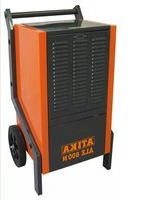
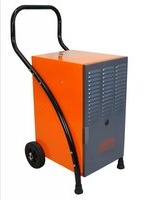
ALE 500 N - Dehumidifier ATIKA - Free user manual and instructions
Find the device manual for free ALE 500 N ATIKA in PDF.

User questions about ALE 500 N ATIKA
0 question about this device. Answer the ones you know or ask your own.
Ask a new question about this device
Download the instructions for your Dehumidifier in PDF format for free! Find your manual ALE 500 N - ATIKA and take your electronic device back in hand. On this page are published all the documents necessary for the use of your device. ALE 500 N by ATIKA.
USER MANUAL ALE 500 N ATIKA
Luftentfeuchter
Original instructions

Page 14
GB Technical modifications reserved!
natural_image
Diagram of a portable industrial machine with labeled parts (H, 8) and directional arrows indicating movement or operation (no text or symbols on the device itself)natural_image
3D diagram of a mechanical component with a numbered arrow and dimension label (no readable text or symbols)Garantie
You may not start to operate the machine until you have read these operating instructions, observed all the instructions given and installed the machine as described!
Keep the operating instructions in a safe place for future use.
Electrical devices do not go into the domestic rubbish. Give devices, accessories and packaging to an ecofriendly recycling.
According to the European Directive 2012/19/EU on electrical and electronic scrap, electrical devices that are no longer serviceable must be separately collected and brought to a facility for an environmentally compatible recycling.
Make sure that the refrigerant circuit of the electrical appliance that is no longer serviceable is not damaged until it is transported to a disposal and collection point. This ensures that the refrigerant does not escape uncontrolled.
Contents
| EC Declaration of Conformity 14 | |
| Extent of delivery 14 | |
| Symbols on the machine 15 | |
| Symbols in the operating instructions 15 | |
| Proper use 15 | |
| Residual risks 14 | |
| Refrigerant | 15 |
| Security advices 15 | |
| ■ Electrical safety advices 16 | |
| Function principle 16 | |
| Assembly | 16 |
| Location of the air dehumidifier 17 | |
| ■ Location | 17 |
| ■ Electric supply 17 | |
| ■ Power system fuse protection 17 | |
| Start-up | 18 |
| ■ Before starting up 18 | |
| ■ Control panel 18 | |
| ■ Powering up 18 | |
| ■ Shutting down | 18 |
| ■ Setting the humidity value | 18 |
| ■ Automatic defroster | 19 |
| ■ Operating hour counter | 19 |
| Water outlet | 19 |
| ■ Removing the water collecting container | 19 |
| ■ Continuous or extended operation | 19 |
| Transport | 20 |
| Cleaning and maintenance | 20 |
| ■ Cleaning the air filter | 20 |
| ■ Removing the filter | 20 |
| ■ Inserting the filter | 20 |
| ■ Cleaning the device | 20 |
| ■ Maintenance | 20 |
| Storage | 20 |
| Guarantee | 20 |
| Possible faults | 21 |
| ■ Fault code | 21 |
| Technical specifications | 22 |
| Wiring diagram | 22 |
| Refrigerant circuit 23 | |
| Spare parts | 23 |
EC Declaration of Conformity
No. (S-No.): 14778
according to Directive 2014/35/EU
We,
Altrad Lescha Atika GmbH
Josef-Drexler-Str. 8, 89331 Burgau - Germany
Here with declare under our sole responsibility that the product Luftentfeuchter (Air dehumidifier) type / model ALE 500 N
Serial number: 000001 - 020000
is conform with the above mentioned EC directives as well as with the provisions of the guidelines below: 2014/30/EU and 2011/65/EU.
Following harmonized standards have been applied:
EN 60335-1:2012+A11:2014+A13:2017+A1:2019+A2:2019+
A14:2019;
EN 60335-2-40:2003+A11:2004+A12:2005+A1:2006+A2:2009+
A13:2012;
EN 62233:2008;
EN 55014-1:2017; EN 55014-2:2015;
EN 61000-3-2:2014; EN 61000-3-3:2013.
Keeping of technical documents at:
Altrad Lescha Atika GmbH - Technical bureau
Josef-Drexler-Str. 8, 89331 Burgau – Germany
Burgau, 20.04.2020
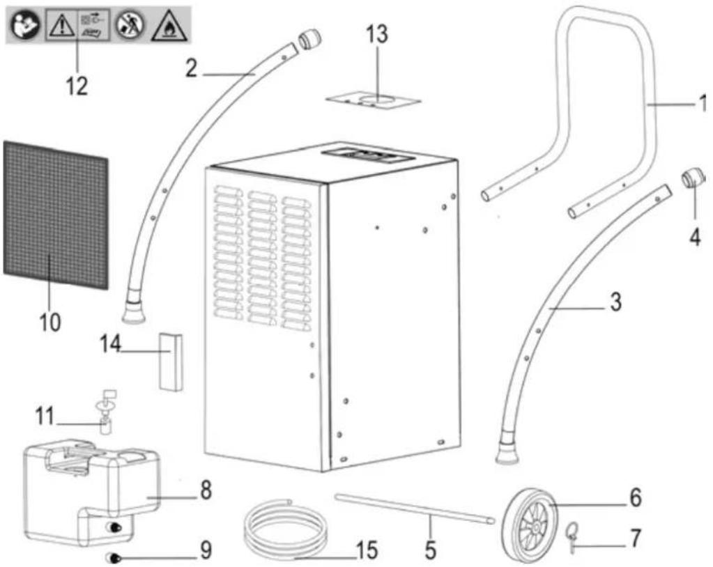
Extent of delivery
After unpacking, check the contents of the box for
▶ completeness
▶ possible transport damage.
Report any damage or missing items to your dealer, supplier or the manufacturer immediately. Complaints made at a later date will not be acknowledged.
• pre-assembled device unit
- 1 carrying handle
- 2 wheels
- 1 hose
- Warranty card
- leg right / left
- 1 screw bag
• 1 operating instruction manual
Symbols on the machine

Read and follow the operating instructions and safety advices before starting up the machine.
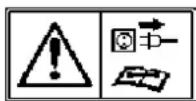
Switch off the air dehumidifier and disconnect the mains power plug before performing cleaning, maintenance or repair work.
Do not tilt the air dehumidifier and do not transport it in horizontal position.

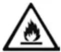
Warning! The dehumidifier is filled with combustible refrigerant R290.
Risk of serious personal injury or damage to property if the device is handled improperly.
Symbols in the operating instructions

Potential hazard or hazardous situation. Failure to observe these instructions may lead to injuries or cause damage to property.

Important information on proper handling. Failure to observe these instructions may lead to malfunction.

User information. This information helps you to use this machine optimally.

Assembly, operation and servicing. Here you are explained exactly what to do.
Proper use
This air dehumidifier is only designed for indoor use to dry moist walls damage caused by water or to reduce the air humidity in confined spaces.
The intended usage also includes compliance with the operating, servicing and repair conditions prescribed by the manufacturer and following the safety instructions included in the instructions.
Follow the relevant accident prevention rules for operation and other generally recognised health and safety at work rules.
Any other use is deemed not to be use as prescribed. The manufacturer is not liable for any type of damage resulting from this: the user bears the sole risk.
Unauthorised modifications on the air dehumidifier exclude a liability of the manufacturer for damages of any kind resulting from it.
Residual risks

Even if used properly, residual risks can exist even if relevant safety regulations are complied with due to the sign determined by the intended purpose.
Residual risks can be minimised if the “Safety advices” and the “Intended usage” as well as the whole of the operating instructions are observed.
Observing these instructions, and taking proper care, will reduce the risk of personal injury or damage to the equipment.
- Risk from electricity when using improper electrical connections.
- Touching live parts of opened electrical components.
In addition, in spite of all the precautionary measures taken, non-obvious residual risks can still exist.
Refrigerant
- The dehumidifier is filled with the environmentally friendly refrigerant R290.
■ This refrigerant belongs to class A3 (according to ISO 817): low toxicity (A) and extremely flammability (3).
■ This refrigerant is odourless. - However, accidentally leaking refrigerant can explode in very unfavourable circumstances when it reaches a certain air concentration, which is highly unlikely when used as intended.
- The dehumidifier must not be installed near burning sources, such as an open flame, a switched-on gas burner or electric heating with glowing spirals.
Safety advices
Before commissioning this product, read and keep to the following advice. Also observe the accident prevention rules of your professional association and the safety provisions applicable in the respective country, in order to protect yourself and others from possible injury.
Pass the safety instructions on to all persons who work with the machine.
① Keep these safety instructions in a safe place.
■ Make yourself familiar with the equipment before using it, by reading and understanding the operating instructions.
- Only use this machine for the intended purpose for which it is designed (see "Proper use").
- Only start up this machine with the specified mains voltage.
- Within his area of work the operator is responsible for third parties.
- The machine must not be operated by children or young people under 16 years of age. They are not aware of the risks associated with the use of these devices.
- Keep children away from the device.
- Only operate the device with complete and correctly attached safety equipment and do not alter anything on the device that could impair its safety.
- Do not switch on the device if it does not function properly or was dropped causing damages to the cable or mains power plug or if another part shows signs of damage.
GB
- Only qualified persons are allowed to carry out repair work on electrical equipment. The user of the device may be severely injured due to improper repair work.
- Switch off the device and disconnect the mains plug if you do not use the device or before you transport or clean it.
- Switch off the device in case of faults, disconnect the mains plug and contact the customer service.
■ Never dip the device in water or another liquid.
■ Do not place objects on the device. - Keep foreign objects away from air inlet/outlet openings.
- Drain the water container before transporting the device to prevent spills.
- Do not tilt the device, otherwise outflowing water may cause damages to the air dehumidifier.
■ Never pour or spray water on the device

Electrical safety
- Use an extension cable in compliance with IEC 60245 (H 07 RN-F) having a core cross-section of at least:
- 1.5 mm ^2 for cable lengths up to 25 m
- 2.5 mm ^2 for cable lengths over 25 m
- Long and thin connection lines result in a voltage drop. The motor does not reach any longer its maximal power; the function of the device is reduced.
- Plugs and coupler outlets on connection cables must be made of rubber, non-rigid PVC or other thermoplastic material of same mechanical stability or be covered with this material.
- When installing the power supply cable observe that it does not interfere, is not squeezed, bended and the plug connection does not get wet.
- Wind off completely the cable when using a cable drum.
- Do not use the cable for purposes for which it is not meant. Protect the cable against heat, oil and sharp edges. Do not use the cable to pull the plug from the socket.
- Check the extension cable on a regular basis and replace it if it is damaged.
- Do not use any defective connection cables.
- Do not set up any provisional electrical connections.
■ Never bypass protective devices or deactivate them. - Only hook up the machine by means of a fault-current circuit breaker (30 mA).

The electrical connection or repairs to electrical parts of the machine must be carried out by a certified electrician or one of our customer service points. Local regulations – especially regarding protective measures – must be observed.

Repairs to other parts of the machine must be carried out by the manufacturer or one of his customer service points.

Use only original spare. Accidents can arise for the user through the use of other spare parts. The manufacturer is not liable for any damage or injury resulting from such action.
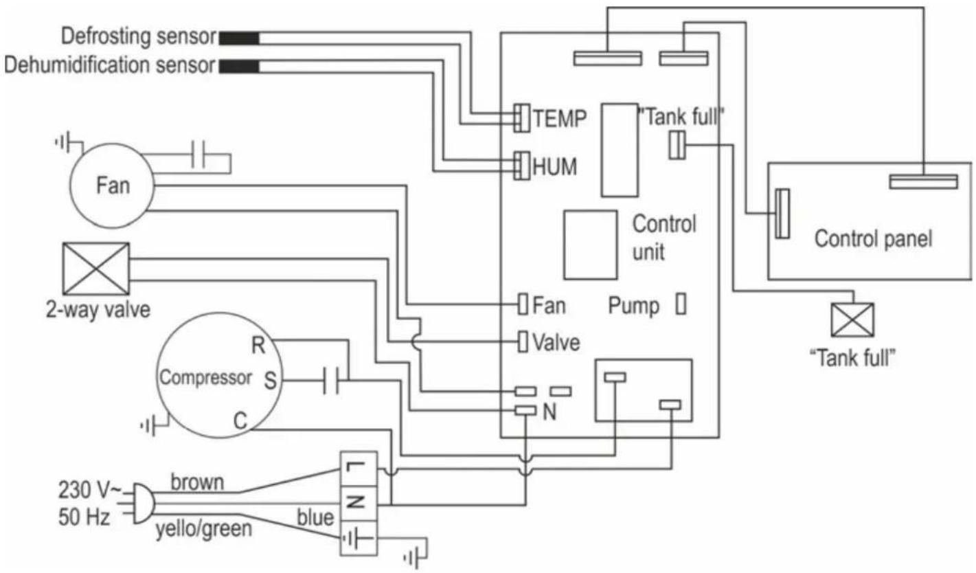
Function principle
This air dehumidifier works on the basis of the condensation principle.
Room air is sucked through a filter and a refrigerating element where water vapour in the air condense as water droplets. Then, the water droplets flow into a condensation water bowl and further into the water container while the dried cold air is piped through the condenser of the device, heated and blown again into the room. The temperature of the blown out air is approx. 2-5 °C above the room temperature. This increase of heat is caused by power introduced in the compressor and fan and by heat which is released by the condensation of the water vapour.
The relative humidity of air is gradually reduced thanks to continuous recirculation of the room air through the device resulting in a quick and gentle drying of the room.
Water vapours move easily and unhindered through the air. Therefore, it is essential to "seal" the room as tight as possible. That means doors and windows must kept closed and entering and leaving the room should be restricted if possible. Otherwise the drying efficiency of the device is considerably impaired.
Assembly
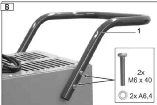
Assembly transport wheels
- Place the air dehumidifier horizontally.
- Remove the transport handle (1). For this, remove the hexagon headed bolts M6x40.
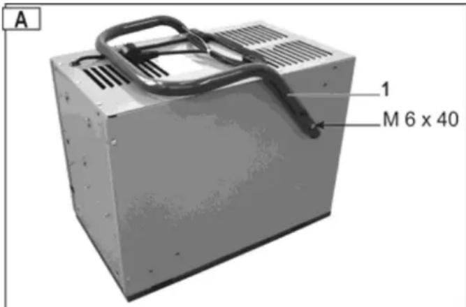
- Turn the transport handle (1). Attach the handle on each side to the housing using 2 hexagon headed bolts M6x40 and washers A6.4.
i Tighten all screws.

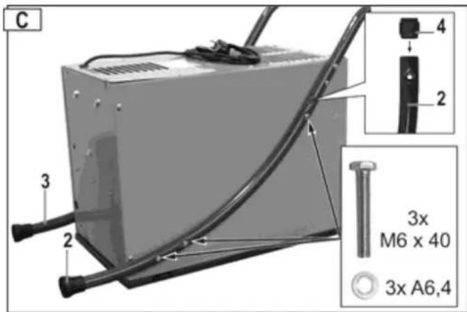
- Insert the connecting pieces (4) in the legs (2/3). Insert the legs in the transport handle and secure them to the enclosure using the 6 hexagon screws M6x40 and the washers

Assembly transport wheels
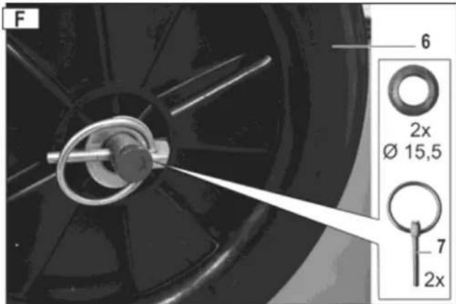
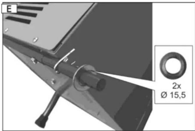
- Secure the wheel axle (5) using the two hexagon head screws M6x30 and install the cotter pins.
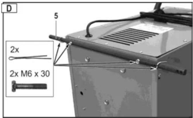
- Secure the cotter pins against dropping out by bending their ends using nippers and slide the washers (∅ 15.5) on the wheel axle.

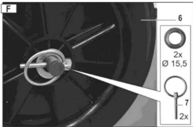
- Slide the wheels (6) and the washers on the wheel axle. Secure the wheels using the securing pins (7).
After assembly, allow the device to stand vertically for at least one hour before powering it up. In this way, the refrigerant in it can settle.
Location of the air dehumidifier
Location
If possible, the air dehumidifier should be placed in the middle of the room in order to have a good air circulation in the whole room.
If this is not possible, locate the air dehumidifier so that air can be sucked and discharged unhindered.
Keep a minimum distance of 10 cm to walls.
Place the air dehumidifier
⇒ horizontally to ensure that the condensed water can flow off unhindered
away from a heat source (e.g. a radiator).
① Make sure that windows and doors of the room to be dehumidified are closed.

The dehumidifier must not be installed near burning sources, such as an open flame, a switched-on gas burner or electric heating with glowing spirals.

The device must be set up, operated and stored in a room with a floor space greater than “ A_min ”. (“ A_min ”: see “Technical data → min. room area”).
Electric supply
Compare the voltage listed on the device's type plate, e.g. 230 V / 50 Hz, with the mains voltage and connect the air dehumidifier to a suited and and properly earthed electrical socket.
Use an electrical socket with a rated voltage of 230 V with a fault-current circuit breaker (30 mA).
Power system fuse protection
10 A
Start-up
Before starting up
Did you transport the air dehumidifier in horizontal position or at an angle large than 45^ ?
i Allow the device to stand in vertical position for at least one hour.
Notes
- The air dehumidifier will not work if the set humidity value is higher than that of the environment.
- Only use the air dehumidifier at a room temperature between 5 °C and 35 °C. The air dehumidifier will not function out of this range.
- Do not operate the air dehumidifier in heavily dust-laden or chloric atmospheres.
- Once the compressor has been started the fan motor and the compressor must run for at least 3 minutes during dehumidification. To prevent damages to the compressor, you should wait for 3 minutes after a shut-down of the air dehumidifier before you restart the device.
- If the room temperature is under 10 °C and the relative humidity of the ambient air is rather low an operation of the air dehumidifier will not be necessary.
- The device's air dehumidification performance depends on room design, room temperature and relative humidity of the room air.
- Drain the container when it is full. Then, reinsert the empty water container so that the device can work again.
- Transport this device only in upright (vertical) position.
- If the device does not work or if the operation is suddenly interrupted for unknown reasons, see "Possible faults".
- When the air dehumidifier is in operation the compressor generates waste heat and the room temperature slightly increases. This is considered a normal process.
Control panel
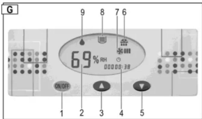
1 → ON/OFF button
2 → Relative humidity (in %) or fault display
3 → "Increase RH" button
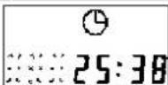
4 → Operating hour counter
5 → "Reduce RH" button
6 → Defrosting icon
7 → "Fan ON" icon
8 → "Water container full" icon
9 → "Dehumidification mode" icon
Continuous display = dehumidification is running (compressor and fan on)
Flashing display = dehumidification is not running (compressor off - fan on)
Fault code
If the fault codes E3 - E4 - E5 are indicated in the "RH display"
→ see "Possible faults".
Powering up
An acoustic signal will sound if you connect the power cable to an electrical socket.
A fault has occurred when this acoustic signal does not sound. Check the power supply cable, the electrical socket and the fuse.
Press the 🔊 button to switch on the power to the air dehumidifier.
The display 2 ➔ "RH of air" indicates the factory-set humidity of air of 60 %. After 5 seconds the display indicates the actual humidity of air.
The "RH" display indicates the humidity of air in a range between 30 % and 90 %.
Shutting down
Press the ON button again to switch off the power to the air dehumidifier.
Setting the humidity value
Press the Button (Increase the RH setting) or (Reduce the RH setting) to set your desired relative humidity of air. If the set RH value is lower than 30 %, the device will continuously dehumidify and the indicator 2 displays "CO".
Hint: Normally, a relative humidity of air between 50 % and 60 % is sufficient to have a convenient indoor climate and to prevent condensation on structural components and furnishing.
If your desired RH value is lower than the actual RH by 3 %, the air dehumidifier will automatically start (compressor). The 🔊 icon (dehumidification) is continuously displayed. If your desired RH value exceeds the actual RH by 3 %, the air dehumidifier will automatically shut down (compressor). The 🔊 icon (dehumidification) is flashing.
Automatic defroster
At a room temperature under 20 °C not only condensation water is generated on the cold evaporator surface, but also ice. This ice blocks the heat exchanger so that the air flow is impeded. The built-in automatic defroster removes the ice from the evaporator. This allows a dehumidification operation down to a temperature of +5 °C.
During defrosting, the sun is displayed on the display, the compressor continues to run, the fan is automatically stopped.
Once the defrosting process is finished the air dehumidifier returns to the dehumidification mode and the 🧑️ icon turns off.
Operating hour counter
The air dehumidifier is equipped with an operating hour counter.
The number of hours during which the device was in operation in the past is displayed after the dehumidifier is turned on. The amount of time during which the device remains on will be added to the already elapsed time.

Water outlet
The water collecting container of the air dehumidifier is equipped with a float switch which turns off the device when the collecting container is full.
① After 45 seconds, compressor and fan will automatically stop, and an acoustic signal will sound. The 📁 icon and the fault code E4 will be displayed.
Another acoustic signal will sound every 5 minutes if the water collecting container is not immediately emptied.
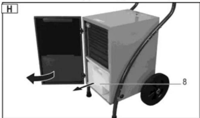
Removing the water collecting container
- Turn off the device.
- Open the enclosure door.
- Remove the container (8) and empty is immediately.
natural_image
Diagram of a portable air purifier with labeled parts (H, 8) and directional arrows indicating movement or flow (no text or symbols beyond labels)- Re-insert the container. Make sure that the container is correctly positioned.
- Close the hinged enclosure cover.
- Restart the air dehumidifier. The 📄 icon and the fault code E4 should no longer be displayed.
Icon and fault code are further displayed? Remove the container again and re-insert it properly.
Continuous or extended operation
In the case of a high humidity of air it is recommended to operate the air dehumidifier in continuous mode. In continuous mode it is not needed to empty the water collecting container.
Proceed as follows:
- Remove the water collecting container from the device.
- Remove the stopper (9).
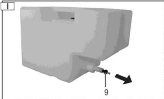
natural_image
3D diagram of a mechanical component with a pin and arrow indicator (no text or symbols)- Re-insert the collecting container in the device.
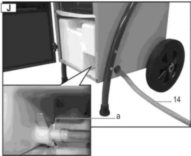
- Guide the hose (14) through the housing. Push the hose on the water drain nozzle (a).
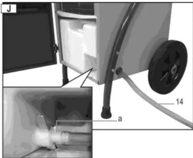
i Pay attention to the following:
→ Make sure that the water can flow out unhindered.
→ Pipe the water preferably to a drain which is positioned at a lower level.
→ Make sure that the hose remains in its position, is routed with a descending gradient, is not kinked or wound up.
Transport
Power off the device and disconnect the mains plug before each transport.
Always transport the air dehumidifier in upright (vertical) position to prevent compressor damages.
Hint: If you have transported the air dehumidifier in another than upright position (horizontal or tilted), allow the air dehumidifier to stand in upright position for at least one hour before starting it up.
Cleaning and maintenance
Turn off the device and disconnect the power plug before each cleaning and maintenance work.
Maintenance and repair work other than those described in this chapter is only allowed to be carried out by service staff.
Only use genuine spare parts. Other than genuine parts may result in unpredictable damages and injury.
Cleaning air filter
A contaminated filter
→ deteriorates the performance of the air dehumidifier,
→ results to contamination inside the device.
i Clean the filter in regular intervals depending on the operating conditions.
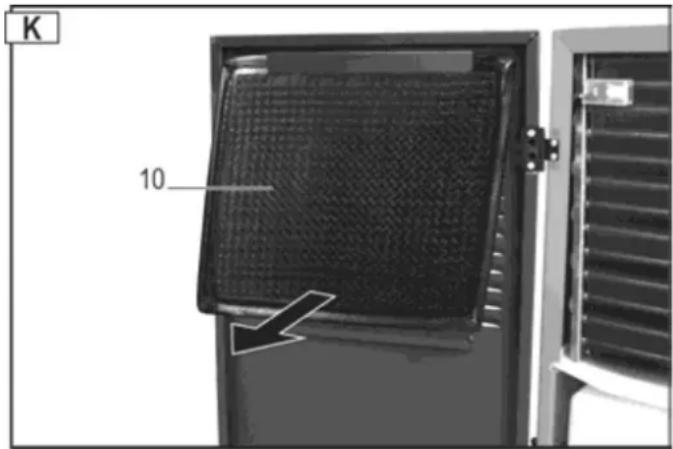
Removing the filter
- Open the enclosure door.
- Remove the filter (10).
Slight contamination
Use a vacuum or slightly knock off the filter to clean it.
Bad contamination
Carefully wash the filter in luke-warm soapy solution (max. 40 °C) and then allow it to dry well. Do not expose the filter to sunlight or other heat sources to dry it.
Inserting the filter
- After cleaning, reinsert the filter in the guides on the enclosure door.
- Close the enclosure door.
Cleaning the device
Clean the device's external surfaces using a wet cloth and a mild cleaning solution (soapy) on a regular basis. Make sure that no water enters the interior of the device.
Do not use detergents or solvents for cleaning because such may attack parts of the device.
Have the interior of the air dehumidifier inspected for contamination by service staff once in a year or more frequently depending on the operating conditions.
Maintenance
The air dehumidifier is designed for a trouble-free operation and a minimum of maintenance.
All movable parts are permanently lubricated.
Inside the device, there are no other parts to be maintained.
Storage
Store unused equipment in a dry, locked place out of the reach of children.
Note the following to extend the service life of your air dehumidifier and to ensure a perfect function:
→ Drain the water collecting container and dry it carefully.
→ Clean the filter.
→ Thoroughly clean the device.
→ Check the air dehumidifier for perfect condition to ensure a safe use of it after a longer period of storage.
→ Carefully cover the air dehumidifier.
Guarantee
Please note the attached guarantee declaration.
Possible faults
Power off the device and disconnect the mains plug before each troubleshooting.
Fault Possible cause Corrective action
| Motor does not start No power supply. Check fuses. | ||
| Mains cable defective. Have it checked (electrician). | ||
| Water collecting container full. Drain the water collecting container. | ||
| Humidity of the room air lower than the set value. | Check the set humidity value and set another value if required. | |
| Only little condensation or no water | Room temperature or humidity of air out of the working range. | a) Check the room temperature (5 °C to 35 °C).b) Check the humidity of air (at least 30% RH).c) Check the set humidity value and set another value if required. |
| Air filter contaminated. Clean the air | filter (see “Cleaning and Maintenance”). | |
| Air supply or exhaust air outlet blocked. | Check. Place the device on another location of required (adhere to the minimum distance to walls (10 cm)). | |
| a) Interior of the device heavily contaminated.b) Refrigerant circuit defective. | Contact the manufacturer or customer service. | |
| Doors and/or windows open. Close doors and/or windows. | ||
| Device shuts down in continuous operation with drain hose | a) Drain hose kinked or wound up.b) Not enough descending gradient. | Re-route the drain hose to allow the water to flow out unhindered. |
| Water frozen in the hose. Take precautions to avoid water freezing. | ||
| Water flows out of the device | Leakage of the water collecting container. | a) Check the water collecting container.b) Replace the water collecting container. |
| Unusual noise or vibrations. | Device is placed on an uneven floor. | Place the device on an even floor. |
| Screws, nuts or other parts loosened. | Tighten the parts.If the parts cannot be tightened, are in the interior of the device or the noise persists: Contact the manufacturer or the responsible customer service respectively | |
Please contact the manufacturer or the customer service if you cannot eliminate a fault although you have carried out all functional tests.
① Immediately put the device out of operation if it does not function properly.
Fault code
Following fault codes can be indicated in the display 2 "Relative humidity of air":
| Fault code | Fault |
| E3 | Humidity sensor defective. |
| E4 | Water collecting container full. |
| E5 | Refrigeration circuit sensor defective. |
i Please contact the manufacturer or customer service of the fault codes E3 or E5 appear.
Technical specifications
Type/ Model ALE 500 N
Year of construction see last page
Air flow rate 350 m³/h
Rated power 700 W
Rated current consumption 3.2 A
max. power 805 W
max. current consumption 3.6 A
Power, fan 10 W
Electrical power supply 230 V\~ / 50 Hz
Power system fuse protection 10 A
Temperature range 5 - 32 °C
Humidity of air range 30 - 90% rel. humidity of air
Dehumidification performance at 30 °C / 80% RH 50 l / 24 h
Protection class IP X0
Freezing pressure 1.0 MPa
Vapour pressure 2.5 MPa
Refrigerant R290
Refrigerant quantity 0.21 kg
max. container volume 5.8 l
"Tank full" LED comes up at 3.9 l
Room volume (at a ceiling height of 2.5 m) 125 – 175 m³
max.room area 50-70 m²
min. room area A_min 10 m²
Sound power level L_WA < 70 dB (A)
Weight 30 kg
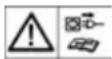
Wiring diagram
flowchart
graph TD
    A["Defrosting sensor"] --> B["2-way valve"]
    C["Dehumidification sensor"] --> B
    D["Fan"] --> B
    E["Compressor"] --> F["R S C"]
    G["230 V~ 50 Hz"] --> H["brown"]
    H --> I["yello/green"]
    J["Blue"] --> K["N"]
    L["Tank full"] --> M["Pump"]
    N["Tank full"] --> O["Control unit"]
    P["TEMP"] --> Q["HUM"]
    R["Tank full"] --> S["Control panel"]
Refrigerant circuit
flowchart
graph TD
    A["Condenser"] --> B["Evaporator"]
    B --> C["Compressor"]
    C --> D["Fan"]
    D --> E["Capillary tube"]
    E --> A
    style A fill:#f9f,stroke:#333
    style B fill:#f9f,stroke:#333
    style C fill:#ccf,stroke:#333
    style D fill:#cfc,stroke:#333
    style E fill:#fcc,stroke:#333
Spare part list
| Pos. | Spare part no. | Denomination | Pos. | Spare part no | Denomination | |
| 1 | 417697 | Carrying handle | 9 | 417620 | Stopper | |
| 2 | 417703 | Leg, RH | 10 41 | 7695 Air filter | ||
| 3 | 417700 | Leg, LH | 11 41 | 7622 Float switch cpl. | ||
| 4 | 417702 | Connecting piece | 12 | 417618 | Safety label | |
| 5 | 417704 | Wheel axle | 13 41 | 7658 Instruction label for control panel | ||
| 6 | 417657 | Transport wheels | 14 | 417721 | Door handle | |
| 7 | 417706 | Securing pin | 15 | 417784 | Hose | |
| 8 41 | 7610 Water collecting container with stopper and float switch Water collecting container |
Always indicate the following when ordering spare parts:
Air dehumidifier type, year of fabrication and spare part number.
Otherwise, no delivery is possible!

natural_image
Diagram of a portable industrial machine with labeled parts (H, 8), showing open door and wheels (no text or symbols beyond labels)natural_image
3D diagram of a mechanical component with a pin and arrow indicator (no text or symbols)natural_image
Diagram of a desktop computer with wheels and a door open, showing directional arrows (no text or symbols)natural_image
3D diagram of a mechanical component with a numbered arrow and dimension label (no readable text or symbols)Гаранция
natural_image
Diagram of a portable industrial machine with wheels and directional arrows indicating movement (no text or symbols)natural_image
3D diagram of a mechanical component with a labeled arrow and number 9, no readable text or symbols present.9 → Symbol "Afrimning"
natural_image
Diagram of a portable industrial machine with labeled parts (H, 8) and directional arrows indicating movement or flow (no text beyond labels)natural_image
3D diagram of a mechanical component with a labeled arrow and number 9, no readable text or symbols present.natural_image
Diagram of a portable industrial machine with labeled parts (H, 8) and directional arrows indicating motion (no text or symbols on the device itself)natural_image
3D diagram of a white plastic container with a small protrusion and an arrow indicating direction (no text or symbols)- Okrenite ručku za transport (1). Pričvrstite ručku na svakoj strani pomoću 2 šesterokutna vijka M6x40 i podloški A6,4 na kućište.
i Dobro pritegnite sve matice.
- Umetnite spojne komade (4) u nogare (2/3). Utaknite nogare u transportnu ručku i pričvrstite ih na kućište sa 6 šesterobridnih vijaka M 6x40 i podložaka A 6,4.
i Dobro pritegnite sve matice.
Montaža transportnih kotača
- Montirajte osovinu kotača (5) s dva šesterobridna vjika (M 6 x 30) i stavite rascjepku.
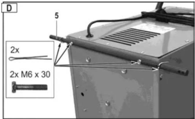
- Osigurajte rascjepku od ispadanja tako da krajeve rascjepke savinete kliještima i navucite podloške (∅ 15,5) na osovinu kotača.
- Stavite kotače (6) i podloške na osovinu. Osigurajte kotače sigurnosnim zaticima (7).
natural_image
Diagram of a portable industrial machine with labeled parts (H, 8), showing open door and wheels (no text or symbols beyond labels)natural_image
3D diagram of a white plastic container with a small protruding pipe and a black arrow pointing to a small numbered component (no text or symbols present)- Ponovno umetnite spremnik u uređaj.
- Provedite crijevo (14) kroz kućište. Stavite crijevo na nastavak za istjecanje vode (a).
i Obratite pozornost na sljedeće:
→ Pazite da voda može uvijek slobodno otjecati.
→ Vodu treba po mogućnosti spojiti na niže položeni odvod.
⇒ Pazite na to da crijevo ostane u svojem položaju da se ne prelomi ili namota.
Transport
Prije svakog transporta isključite uređaj i izvadite mrežni utikač.
Kod narudžbe rezervnih dijelova obavezno navedite: tip odvlaživača zraka, godinu proizvodnje i broj rezervnog dijela. U suprotnom nije moguće izvršiti ispravnu isporuku!

natural_image
Diagram of a portable industrial machine with labeled parts (H and 8), showing open door, wheels, and directional arrows (no text or symbols beyond labels)natural_image
3D diagram of a mechanical component with a labeled arrow and number 9, no readable text or symbols present.natural_image
Diagram of a portable industrial machine with wheels and a door open, showing directional arrows (no text or symbols)natural_image
3D diagram of a mechanical component with a numbered arrow and label '9' (no text or symbols beyond labels)natural_image
Diagram of a portable air purifier with labeled parts (H and 8), showing internal components and directional arrows (no text or symbols beyond labels)natural_image
3D diagram of a mechanical component with a numbered arrow and label '9' (no text or symbols beyond labels)conform directive: 2014/35/UE
Prin prezenta, noi
Altrad Lescha Atika GmbH
Josef-Drexler-Str. 8, 89331 Burgau – Germany
natural_image
Diagram of a portable industrial machine with labeled parts (H, 8) and directional arrows indicating motion or movement (no text or symbols on the device itself)natural_image
3D diagram of a mechanical component with a labeled arrow and number 9, no readable text or symbols present.natural_image
Close-up of a black industrial air vent with mesh insulation and ventilation slots (no text or symbols visible)Murdărire ușoară
natural_image
Diagram of a portable industrial machine with labeled parts (H and 8), showing internal components and directional arrows indicating motion (no text or symbols beyond labels)natural_image
3D diagram of a white plastic container with a small protruding pipe and a black arrow pointing to a small labeled component (no text or symbols beyond the number 9)natural_image
Diagram of a portable industrial machine with wheels and a door open, showing directional arrows (no text or symbols)natural_image
3D diagram of a mechanical component with a labeled arrow and number 9, no readable text or symbols present.- V napravo ponovno vstavite posodo za vodo.
- Skozi ohišje speljite cev (14). Cev vtaknite na nastavek za odtok vode (a).

GB Year of construction