IS NM 360 - Motion detector STEINEL - Free user manual and instructions
Find the device manual for free IS NM 360 STEINEL in PDF.

| Product type | Infrared motion detector |
| Brand | Steinel |
| Model | IS NM 360 |
| Power supply | 230 – 240 V, 50/60 Hz |
| Max. power (incandescent lamp) | 1000 W |
| Max. power (fluorescent tube) | 500 W (cos φ = 0.5) |
| Max. power (LED/energy-saving) | 6 x 58 W max., C ≤ 132 μF |
| Detection angle | 360° with 90° aperture angle |
| Detection range | Max. 8 m (mounting height 1.75 – 2 m) |
| Time delay | 5 s – 15 min (continuously adjustable) |
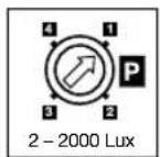
| Twilight setting | 2 – 2000 lux |
| Programs | 4 programs: standard, evening comfort, evening/morning comfort, midnight |
| Permanent light | Switchable (4 h) with mains switch |
| Protection class | IP 54 |
| Operating temperature | -20 °C to +50 °C |
| Recommended mounting height | 2 m max. for 8 m range |
| Maintenance and cleaning | Clean the lens with a damp cloth (no detergent) |
| Safety | Installation by a professional, cut power before mounting |
| Warranty | 36 months |
| Repairability | Use original parts, repair by specialized workshops |
Frequently Asked Questions - IS NM 360 STEINEL
User questions about IS NM 360 STEINEL
0 question about this device. Answer the ones you know or ask your own.
Ask a new question about this device
Download the instructions for your Motion detector in PDF format for free! Find your manual IS NM 360 - STEINEL and take your electronic device back in hand. On this page are published all the documents necessary for the use of your device. IS NM 360 by STEINEL.
USER MANUAL IS NM 360 STEINEL
① Socket Tool Company Ltd
Unit 714 Northwest Business Park · Kishane Drive Balycoolin · Dublin 15 · Tel: 00353/1/8809120 Fax: 00353/1/8612061 - info@sockettool.ie
F STEINEL FRANCE SAS · ACTICENTRE - CRT 2 Rue des Famards - Bât. M - Lot 3 F-69918 Lesouin Cedex · Tél. +33/3/20 30 34 00 Fax: +33/3/20 30 34 20 · info@steinefrance.com
NL VAN SPIJK AGENTUREN
Postbus 2, 5688 HP OIRSCHOT · De Schoper 260 5688 HP OIRSCHOT · Tel: 0499 571810 Fax: 0499 575795 · vsa@vansnik.nl · www.vansnikr
B VSA handel Byba
Hageberg 29 · B-2440 Geel Tel: +32/14/256050 · Fax: +32/14/256059 info@vsahandel.be · www.vsahandel.be
A. R. Tech. - 19, Rue Eugène Ruoper, Cloche D'Or BP 1044 · L-1010 Luxembourg · Tel: +352/49/3333 Fax: +352/40/2634 · com@artech.lu
①STEINEL Italia S.r.l.
Largo Donegani 2 · I-20121 Milano el: +39/02/96457231 · Fax: +39/02/96459295 info@stemel.it · www.stemel.it
E SAET-94 S.L. · C/ Trepadella, n° 10 · Pol. Ind. Castelbisbal Sud · E-09756 Castelbisbal (Barcelona) Tel: +34/93/772 28 49 · Fax: +34/93/772 01 80 saet94@saet94.com
MLZ SAN. ve TIC. A.S.
Tersane Cad. No: 63 - TR-34420 Karakoy/Istanbul
Tel: +90/212/2920664 Fax: · Fax: +90/212/2920666 www.atersan.com - info@atersan.com
©Z ELNAS s.r.o. - Oblekovice 394 - CZ-67181 Zrojmo
Tel: +420/515/220126 · Fax: +420/515/244347
SLO LOG Zabnica D.O.O.
natural_image
Simple line drawing of a mechanical component with a cylindrical base and a rectangular block (no text or symbols)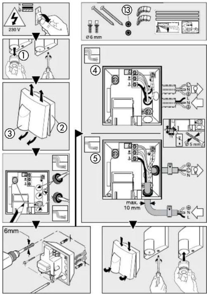
flowchart
graph TD
    A["230 V"] --> B["①"]
    B --> C["②"]
    C --> D["③"]
    D --> E["④"]
    E --> F["⑤"]
    F --> G["6mm"]
    style A fill:#f9f,stroke:#333
    style G fill:#bbf,stroke:#333
2
flowchart
graph TD
    A["1x"] --> B["5 sec.-15 min"]
    B --> C["2x"]
    C --> D["4h"]
    style A fill:#f9f,stroke:#333
    style B fill:#ccf,stroke:#333
    style C fill:#cfc,stroke:#333
    style D fill:#fcc,stroke:#333
    subgraph Timeframe
        E["1X"] --> F["2X"]
        F --> G["360°"]
        G --> H["4h"]
    end
    style E fill:#fff,stroke:#333
    style F fill:#fff,stroke:#333
    style G fill:#fff,stroke:#333
    style H fill:#fff,stroke:#333
3
flowchart
graph TD
    A["Light Path Adjustment"] --> B["Sensor Position"]
    B --> C{Time: 2000 Lux}
    C -->|Yes| D["Light Path Display"]
    C -->|No| E["Sensor Layout"]
    D --> F["Sensor Position"]
    E --> G["Sensor Layout"]
    F --> H["Clock Icon"]
    G --> I["Clock Icon with Plus/Down Arrow"]
    style A fill:#f9f,stroke:#333
    style B fill:#ccf,stroke:#333
    style C fill:#cfc,stroke:#333
    style D fill:#fcc,stroke:#333
    style E fill:#cff,stroke:#333
    style F fill:#ffc,stroke:#333
    style G fill:#ffc,stroke:#333
    style H fill:#fff,stroke:#333
    style I fill:#fff,stroke:#333
    style_J["Camera Icon"] --> K["Light Path Display"]
    K --> L["Sensor Position"]
    L --> M{Time: 2000 Lux}
    M -->|Yes| N["Light Path Display"]
    M -->|No| O["Sensor Layout"]
    N --> P["Sensor Position"]
    O --> Q["Sensor Layout"]
D Montageanleitung
GB Installation instructions
Dear customer,
Congratulations on purchasing your new STEINEL infrared sensor and thank you for the confidence you have shown in us. You have chosen a high-quality product that has been manufactured, tested and packed with the greatest care.
Please familiarise yourself with these instructions before attempting to install the sensor light since prolonged reliable and trouble-free operation will only be ensured if it is installed properly. We hope your new STEINEL infrared sensor will bring you lasting pleasure.
System components
① Mini sensor
② Wall mount
③ Designer trim
④ Connection, concealed wiring with load
⑤ Connection, exposed wiring with load
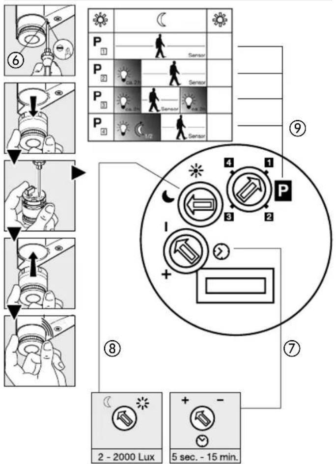
⑥ Engagement lug for removing sensor unit
⑦ Time setting
⑧ Twilight setting
⑨ Programme setting
⑩ Principle
⑪ Adjusting the detection zone
⑫ Manual override
⑬ Sealing plug
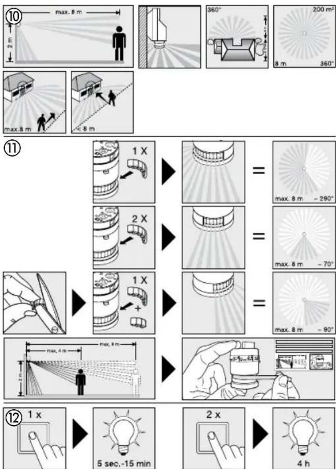
Principle ⑩
The IS NM 360 combines timeless, aesthetic design with practical additional benefits. There are 4 sensor and NightMatic combinations to choose from for automatically switching light "ON" and "OFF" just as you please. The integrated high-performance infrared sensor is equipped with a double 360° sensor that detects the invisible heat emitted by moving objects (persons, animals etc.). The heat detected in this way is converted electronically into a signal that switches the light on automatically. Heat is not detected through
obstacles, such as walls or panes of glass. Heat radiation of this type will, therefore, not trigger the sensor. The unit achieves a coverage angle of 360^ with an aperture angle of 90^ . A sneak-by guard ensures coverage below the sensor. Important: The most reliable way of detecting movement is to install the infrared sensor so that it points across the direction in which a person would walk and by ensuring that no obstacles (such as trees, walls etc.) obstruct the line of vision. Reach is restricted when you walk straight towards the sensor.
Safety warnings
During installation, the electric power cable to be connected must be voltage-free. Therefore, switch off the power first and use a voltage tester to make sure the wiring is off circuit.
■ Installing this infrared sensor involves work on the mains voltage supply. This work must therefore be carried out by a specialist in
accordance with the applicable national wiring regulations and electrical operating conditions. (B)-VDE 0100, (A)-OVE/ÖNORM E8001-1, (SH)-SEV 1000).
■ Only use genuine replacement parts.
■ Repairs must only be made by specialised workshops.
Installation
The site of installation should be at least 50 cm away from another light because heat radiated from it may activate the system. To obtain the specified reach of 8 m, the sensor should be installed at a height of no more than 2 m.
Connecting the mains and load supply lead (see illustration)
The mains supply lead is a 3-core cable.
L = phase conductor (usually black or brown)
N = neutral conductor (usually blue)
PE = protective-earth conductor (green/yellow)
If you are in any doubt, identify the conductors using a voltage tester; then switch off the power again. Connect phase conductor (L), neutral conductor (N) and protective earth conductor (PE) to the terminal block. Getting the cable connections crossed will produce a short circuit in the unit or in your fuse box. In this case, you must identify the individual cables and re-connect them.
Note: A mains switch for switching the unit "ON" and "OFF" may of course be installed in the mains supply lead. A mains switch is required for the manual override function (see Manual override function ⑫).
Adjusting the detection zone ⑪
The detection zone can be limited to suit requirements. The shrouds supplied with the unit can be used to mask out as many lens segments as you wish. This prevents the light from being activated unintention-
nally, e.g. by cars, passers-by etc., and allows you to target danger spots. The shrouds and film covers can be cut along the pre-grooved divisions. Then you simply clip them onto the lens.
Permanent light function ⑫
If a mains switch is installed in the mains supply lead, the light is capable of the following functions in addition to the simple "ON/OFF" function:
Sensor operation
1) Switch light "ON" (when light is "OFF")
Turn switch "OFF" and "ON" once. Light stays "ON" for the period selected.
2) Switch light "OFF"
(when light is "ON"): Turn switch "OFF" and "ON" once. The light goes out or switches to sensor mode.
Functions ⑦, ⑧, ⑨
Once installed, the sensor can be put into operation. Control dials are provided on the sensor unit for selecting time, twilight and programme settings. After pressing the
Switch-off delay (time setting) ⑦
(factory setting: 5 sec.)
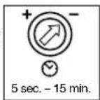
engagement lug ⑥ with a flat-bladed screwdriver, the sensor unit can be removed for ease of setting. The IS NM 360 and connected light switch to permanent light "ON".
Light "ON" time can be adjusted continuously from 5 sec. to 15 min. Control dial set to - = shortest time (5 sec.) Control dial set to + = longest time (15 min.)
When setting the detection zone, it is recommended to select the shortest time -.
Functions ⑦, ⑧, ⑨
Twilight setting (response threshold) ⑧ (factory setting: daylight operation 2000 lux)
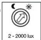
The sensor's response threshold can be infinitely varied from 2 - 2000 lux. Control dial set to = daylight operation at approx. 2000 lux.
Control dial set to = night-time operation at approx. 2 lux.
To adjust the detection zone in daylight, the control dial must be set to * (daylight operation).
Programme setting ⑨ (factory setting: programme 1)
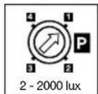
Standard programme 1
- Sensor "ON" only in response to movement as from the selected light threshold setting
Comfort programme 2 - evening
- Sensor "ON" for approx. 2 hours as from the selected twilight setting, followed by normal sensor mode (4)

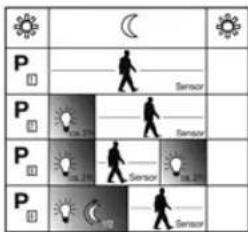
Comfort programme 3 - evening/morning
- Sensor "ON" for approx. 2 hours as from the selected twilight setting, followed by normal sensor mode and, once again, approx. 2 hours of constant light as from the twilight setting at dawn
Comfort programme 4 - midnight* - Sensor ON to the middle of the night ^4 as from the selected twilight setting, followed by standard programme
*Note on comfort programme 4 - midnight
The sensor contains no integrated clock, the middle of the night is determined by the length of the dark phases. To work perfectly, therefore, it is important for the connected load to be permanently supplied with power during this period. During the first night (calibration phase) basic brightness remains activated
throughout the night. Values remain saved even in the event of mains power failure. We recommend not to interrupt the power supply in programme 4. As the values are determined over several nights, the connected load should, in the event of any fault, be observed over several nights to ascertain whether the switch-off time moves towards midnight.
Troubleshooting
| Malfunction Cause | Remedy | |
| Sensor without power | ■ Fuse faulty, not switched "ON", break in wiring■ Short circuit | ■ Fit new fuse; switch "ON" mains switch; check wiring with voltage tester■ Check connections |
| Sensor will not switch "ON" | ■ Twilight control set to night-time mode during daytime operation■ Bulb faulty■ Mains switch OFF■ Fuse faulty■ Detection zone not properly targeted■ Internal electrical fuse has been activated (red LED flashing rapidly) | ■ Re-adjust (control ®)■ Change bulb■ Switch ON■ Renew fuse, check connection if necessary■ Re-adjust■ Switch sensor "OFF" and "ON" again after approx. 5 sec. |
| Sensor will not switch OFF | ■ Continued movement in detection zone■ Sensor unit is not properly engaged | ■ Check detection zone and re-adjust if necessary■ Lightly press sensor unit to clip it into place |
| Sensor does not switch off at around midnight | ■ External light source (e.g. another motion detector or light) inactivating the sensor | ■ Shade sensor from extraneous light, observe sensor for several days as it takes time to return to the correct value |
| Sensor reach has changed | ■ Differing ambient temperatures | ■ Use shrouds to define detection zone precisely |
| Red LED flashing rapidly | ■ Internal fuse activated | ■ Switch light "OFF" and "ON" again after 5 sec. |
Troubleshooting
| Malfunction Cause | Remedy | |
| Sensor responds when it should not | ■ Wind is moving trees and bushes in the detection zone■ Cars in the street are being detected■ Sudden change in temperature due to weather (wind, rain, snow) or air expelled from fans, open windows | ■ Change zone■ Change zone■ Adjust detection zone or change site of installation |
Technical specifications
| Output: |
| Filament bulbs, 1000 W max., operating on 230 V AC |
| Fluorescent lamp, 500 W max., at cos φ = 0.5, inductive load at 230 V AC |
| 6 x 58 W each max., C ≤ 132 μF operating on 230 V AC |
| Voltage: 230 – 240 V, 50/60 Hz |
| Angle of coverage: 360° with 90° angle of aperture and sneak-by guard |
| Sensor reach: 8 m max. all round (mounted at a height of 1.75 – 2 m) |
| Time setting: 5 sec. – 15 min. |
| Twilight setting: 2 – 2000 lux |
| Programme setting: 4 function programmes geared to practical requirements |
| ON time: selectable (4 hours) provided Switch in mains power supply lead |
| Enclosure: IP 54 |
| Temperature range: -20 °C to +50 °C |
^1) Fluorescent lamps, low-energy bulbs, LED lights with electronic ballast (total capacity of all connected ballasts below the value specified).
Operation/Maintenance
The sensor is suitable for switching light on automatically. Weather conditions may affect the way the sensor works. Strong gusts of wind, snow, rain or hail may cause the light to come on when it is not
wanted because the sensor is un- able to distinguish sudden changes of temperature from sources of heat. The detector lens may be cleaned with a damp cloth if it gets dirty (do not use cleaning agents).
CE Declaration of conformity
This product complies with Low Voltage Directive 2006/95/EC, EMC
Directive 2004/108/EC and RoHS Directive 2002/95/EC.
Functional warranty
This STEINEL product has been manufactured with utmost care, tested for proper operation and safety and then subjected to random sample inspection. STEINEL guarantees that it is in perfect condition and proper working order. The warranty period is 36 months and starts on the date of sale to the consumer. We will remedy defects caused by material flaws or manufacturing faults. The warranty will be met by repair or replacement at our own discretion. The warranty shall not cover damage to wear parts, damage or defects caused by improper treatment or maintenance. Further consequential damage to other objects shall be excluded. Claims under the warranty will only
be accepted if the unit is sent fully assembled and well packed with a brief description of the fault, a receipt or invoice (date of purchase and dealer's stamp) to the appropriate Service Centre.
Repair Service:
Our Customer Service Department will repair faults not covered by warranty or after the warranty period. Please send a well packed to your Centre.

Reparationsservice: After garantins
Programinnstilling ⑨ (Forinnstilling: program 1)