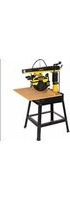
DW720 - Saw DEWALT - Free user manual and instructions
Find the device manual for free DW720 DEWALT in PDF.


User questions about DW720 DEWALT
0 question about this device. Answer the ones you know or ask your own.
Ask a new question about this device
Download the instructions for your Saw in PDF format for free! Find your manual DW720 - DEWALT and take your electronic device back in hand. On this page are published all the documents necessary for the use of your device. DW720 by DEWALT.
USER MANUAL DW720 DEWALT
natural_image
Technical line drawing of a mechanical assembly with no visible text or symbols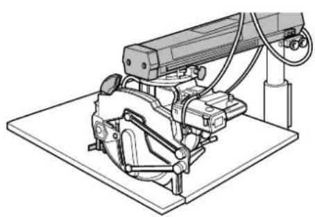
natural_image
Technical line drawing of a mechanical assembly with no visible text or symbolsF5 G1
text_image
7574 72 73 71 73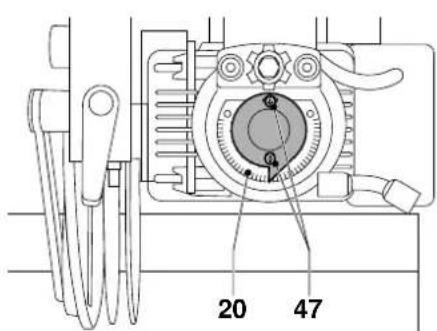
text_image
20 47G2
G3
G4
text_image
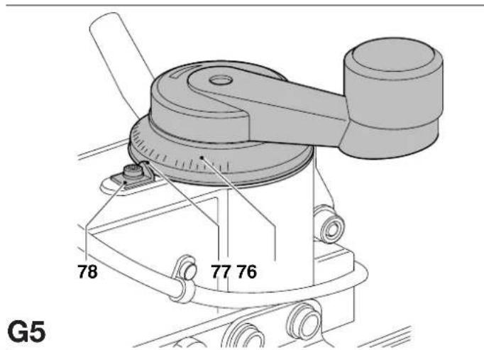
78 77 76 G5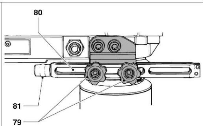
text_image
80 81 79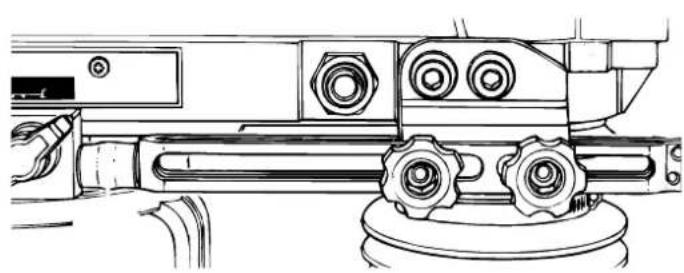
natural_image
Technical line drawing of a mechanical assembly with gears and housing (no text or symbols)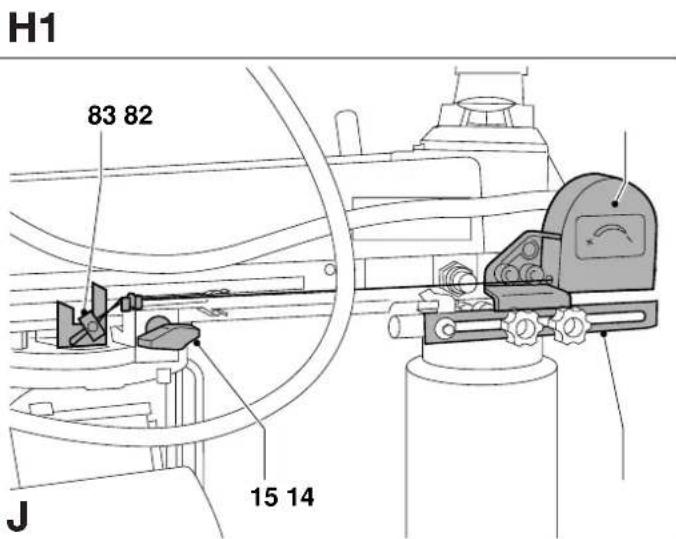
text_image
H1 83 82 J 15 14H2

text_image
K1 K2 K3 K4 K5

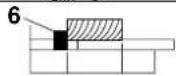
330 mm 330 mm 245 mm 225 mm 640 mm
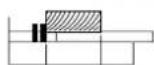
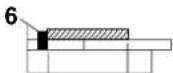
380 mm
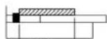
380 mm
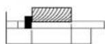
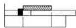
245 mm
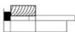
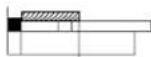
260 mm
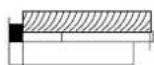
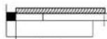
640 mm
K
text_image
88 87 8685 84L1
natural_image
Technical diagram of a mechanical component with labeled part 89 (no text or symbols beyond label)L2 L3

natural_image
Technical line drawing of a mechanical assembly with a cylindrical component and mounting base (no text or symbols)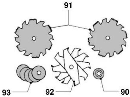 M1 M1 | 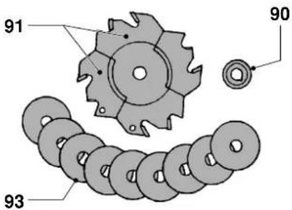 M2 M2 | 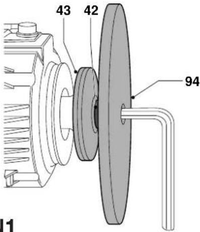 N N | |
 N2 N2 | 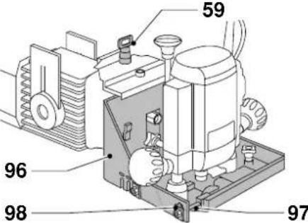 O1 O1 | 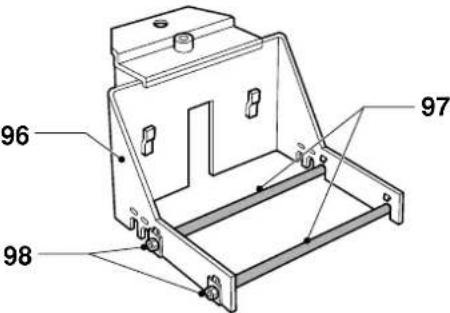 O2 O2 | |
 O3 O3 | 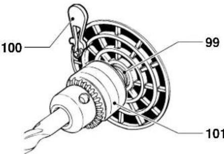 P P | 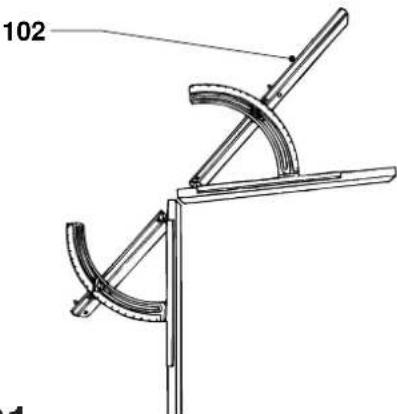 Q1 Q1 | |
 |  R1 R1 | ||
text_image
112 109 R2 R3 112 108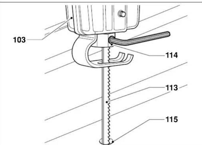
text_image
103 114 113 115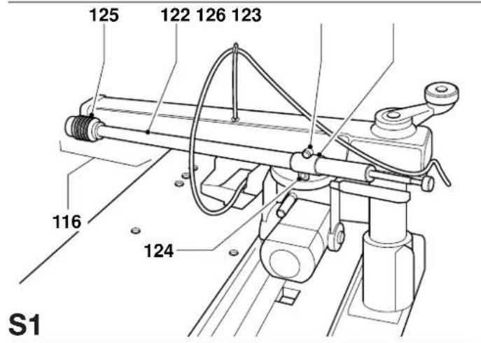
text_image
125 122 126 123 116 124 S1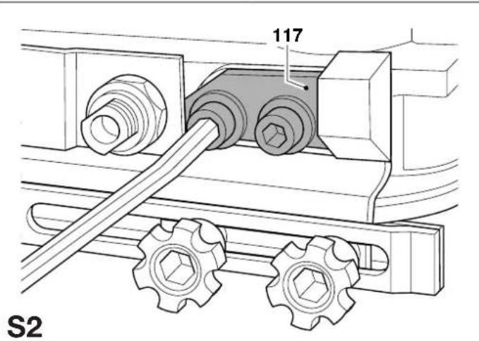
text_image
117 S2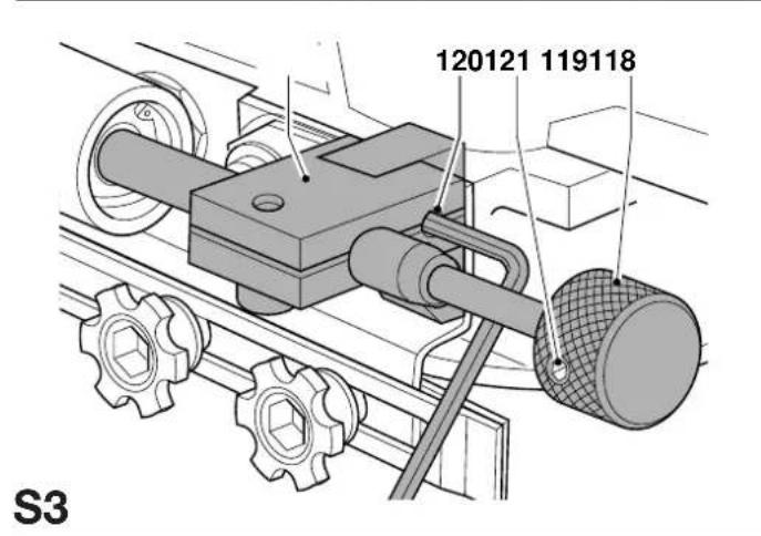
text_image
120121 119118 S3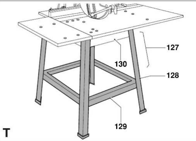
text_image
127 130 128 129 TRADIALARMSAV DW720
Tillykke!
You have chosen a DeWALT product. Years of experience, thorough product development and innovation make DeWALT one of the most reliable partners for professional users.
Table of contents
| Technical data en - 1 |
| EC-Declaration of conformity en - 1 |
| Safety instructions en - 2 |
| Package contents en - 3 |
| Description en - 3 |
| Electrical safety en - 3 |
| Mains plug replacement (U.K. & Ireland only) en - 3 |
| Using an extension cable en - 3 |
| Assembly and adjustment en - 4 |
| Instructions for use en - 6 |
| Optional accessories en - 7 |
| Maintenance en - 9 |
| Guarantee en - 9 |
| Quick reference chart en - 10 |
Technical data
| DW720 | |||
| Motor power (input) | W | 1450 | |
| Motor power (output) | W | 1100 | |
| Voltage | V | 230 | |
| Blade diameter (max) | mm | 250 | |
| Blade bore | mm | 30 | |
| Spindle diameter | mm | 20 | |
| No load speed, 50 Hz | min^-1 | 2800 | |
| No load speed, 60 Hz | min^-1 | 3400 | |
| Depth of cut at 90° | mm | 68 | |
| Depth of cut at 45° | mm | 50 | |
| Max. crosscut capacity at 0°in 25 mm stock | mm | 380 | |
| Max. mitre cut capacity at 45°in 25 mm stock | righthand | mm | 245 |
| lefthand | mm | 260 | |
| Max. crosscut width | mm | 380 | |
| Max. rip cut width | mm | 640 | |
| Overall dimensions | mm | 148 x 95 x 150 | |
| Dust extraction adapter | mm | 100 | |
| Weight | kg | 52.5 | |
Standard equipment:
TCT blade, blade guard and tools, no-volt release switch.
| Fuses: | ||
| Europe | 230 V tools | 10 Amperes, mains |
| U.K. & Ireland | 230 V tools | 13 Amperes, in plugs |
The following symbols are used throughout this manual:

Denotes risk of personal injury, loss of life or damage to the tool in case of non-observance of the instructions in this manual.

Denotes risk of electric shock.

Sharp edges.
EC-Declaration of conformity

DW720
D=WALT declares that these Power Tools have been designed in compliance with: 89/392/EEC, 89/336/EEC, 73/23/EEC, EN 61029, EN 55104, EN 55014, EN 61000-3-2 & EN 61000-3-3.
For more information, please contact DEWALT at the address below or refer to the back of the manual.
Level of sound pressure according to 86/188/EEC & 89/392/EEC, measured according to DIN 45635:
| DW720 | |||
| L_pa | (sound pressure) | dBi(A)^* | 83.7 |
| L_uaa | (acoustic power) | dBi(A) | 90.7 |
* at the operator's ear

Take appropriate measures for the protection of hearing if the sound pressure of 85 dB(A) is exceeded.
Weighted root mean square acceleration value according to DIN 45675:
| DW720 |
| < 2.5 m/s ^2 |
TÜV Rheinland
Director Engineering and Product Development
Horst Großmann
X. fopsmann
D-65510, Idstein, Germany
Safety instructions
When using Power Tools, always observe the safety regulations applicable in your country to reduce the risk of fire, electric shock and personal injury. Read the following safety instructions before attempting to operate this product.
Keep these instructions in a safe place!
General
1 Keep work area clean
Cluttered areas and benches can cause accidents.
2 Consider work area environment
Do not expose Power Tools to humidity. Keep work area well lit. Do not use Power Tools in the presence of inflammable liquids or gases.
3 Guard against electric shock
Prevent body contact with earthed surfaces (e.g. pipes, radiators, cookers and refrigerators).
For use under extreme conditions (e.g. high humidity, when metal swarf is being produced, etc.) electric safety can be improved by inserting an isolating transformer or a (FI) earth-leakage circuit-breaker.
4 Keep children away
Do not let children come into contact with the tool or extension cord. Supervision is required for those under 16 years of age.
5 Extension cords for outdoor use
When the tool is used outdoors, always use extension cords intended for outdoor use and marked accordingly.
6 Store idle tools
When not in use, Power Tools must be stored in a dry place and locked up securely, out of reach of children.
7 Dress properly
Do not wear loose clothing or jewellery. They can be caught in moving parts. Preferably wear rubber gloves and non-slip footwear when working outdoors. Wear protective hair covering to keep long hair out of the way.
8 Wear safety goggles
Also use a face or dust mask in case the operations produce dust or flying particles.
9 Beware of maximum sound pressure
Take appropriate measures for the protection of hearing if the sound pressure of 85 dB(A) is exceeded.
10 Secure workpiece
Use clamps or a vice to hold the workpiece. It is safer and it frees both hands to operate the tool.
11 Do not overreach
Keep proper footing and balance at all times.
12 Avoid unintentional starting
Do not carry the plugged-in tool with a finger on the switch. Be sure that the switch is released when plugging in.
13 Stay alert
Watch what you are doing. Use common sense. Do not operate the tool when you are tired.
14 Disconnect tool
Shut off power and wait for the tool to come to a complete standstill before leaving it unattended. Unplug the tool when not in use, before servicing or changing accessories.
15 Remove adjusting keys and wrenches
Always check that adjusting keys and wrenches are removed from the tool before operating the tool.
16 Use appropriate tool
The intended use is laid down in this instruction manual. Do not force small tools or attachments to do the job of a heavy-duty tool. The tool will do the job better and safer at the rate for which it was intended.
Warning! The use of any accessory or attachment or performance of any operation with this tool, other than those recommended in this instruction manual may present a risk of personal injury.
17 Do not abuse cord
Never carry the tool by its cord or pull it to disconnect from the socket. Keep the cord away from heat, oil and sharp edges.
18 Maintain tools with care
Keep the tools in good condition and clean for better and safer performance. Follow the instructions for maintenance and changing accessories. Inspect the tool cords at regular intervals and, if damaged, have them repaired by an authorized DEWALT repair agent. Inspect the extension cords periodically and replace them if damaged. Keep all controls dry, clean and free from oil and grease.
19 Check for damaged parts
Before using the tool, carefully check it for damage to ensure that it will operate properly and perform its intended function. Check for misalignment and seizure of moving parts, breakage of parts and any other conditions that may affect its operation. Have damaged guards or other defective parts repaired or replaced as instructed.
Do not use the tool if the switch is defective. Have the switch replaced by an authorized DeWALT repair agent.
20 Have your tool repaired by an authorized DEWALT repair agent
This Power Tool is in accordance with the relevant safety regulations. To avoid danger, electric appliances must only be repaired by qualified technicians.
Additional safety rules for radial arm saws
- Protect the electric power supply with a suitable fuse or circuit breaker.
- Keep the bearing tracks in the arm and the bearings on the roller head assembly clean and free from grease.
- Before switching ON, make sure that the fence is in the correct position. The blade should not contact the material until the saw is pulled by the handle.
- Always set the finger guard so that it passes through the pre-cut slot in the fence and/or 3mm above the surface of the material being cut (except when ripping).
- When ripping, keep the riving knife adjusted to the correct distance from the blade (1 - 3 mm) and make sure the kickback fingers are properly adjusted.
- When ripping, always check the direction of feed.
- Regularly check the adjustments for accuracy and adjust as required.
- Make sure that the blade rotates in the correct direction and that the teeth are pointing towards the fence.
- Make sure all clamp handles are tight before starting operation.
- Never run the machine without all guards in place.
- When not in use, protect the saw blade completely using the blade guard.
- When not in use, when changing blades or carrying out maintenance, disconnect the machine from the power supply.
- Always use sharp blades of the correct type designed for the workpiece. The recommended blade diameter is stated in the technical data.
- Do not wedge anything against the motor fan to hold the motor shaft.
- Do not force the cutting action. (Stalling or partial stalling of the motor can cause major damage. Allow the motor to reach full speed before cutting.)
- Do not lift the machine by its worktable.
- Do not cut ferrous metals, non-ferrous metals or masonry.
- Do not apply lubricants to the blade when it is running.
- Do not place either hand in the blade area when the saw is connected to the power source.
- Do not reach around behind the saw blade when in use.
- Do not place hands closer than 150 mm from the saw blade while cutting.
- Do not use damaged or cracked saw blades.
Residual risks
The following risks are inherent to the use of radial arm saws:
In spite of the application of the relevant safety regulations and the implementation of safety devices, certain residual risks cannot be avoided.
These are:
- Impairment of hearing.
- Risk of accidents caused by the uncovered parts of the rotating saw blade.
- Risk of injury when changing the blade.
- Risk of squeezing fingers when opening the guards.
- Health hazards caused by breathing dust developed when sawing wood, especially oak, beech and MDF.
Package contents
The package contains:
1 Partly assembled machine
5 Table top sections
1 Fence
4 Table supports
1 Height adjustment crank
1 Motor, yoke and roller head assembly with no-volt release switch
1 Saw blade
1 Guard assembly
1 Dust extraction adapter
1 Set of parts for table extension:
8 M8 x 30 flat slotted head bolts
8 D8 Belleville washers
8 M8 nuts
8 D8 flat washers
2 Skinpacks containing:
1 multifunctional spanner
1 ring/open spanner
1 box spanner 13 mm
5 Allen keys (2.5, 3, 4, 5 & 8 mm)
1 cross head screw
4 M10 x 16 bolts
4 M10 nuts
4 D10 Belleville washers
6 M8 x 30 flat slotted head bolts
6 D8 Belleville washers
6 M8 nuts
6 D8 flat washers
1 cable clamp
1 cable support
2 table clamps
2 clamps for return spring
1 Instruction manual
1 Exploded drawing
- Check for damage to the tool, parts or accessories which may have occurred during transport.
• Take the time to thoroughly read and understand this manual prior to operation.
Description (fig. A1 & A2)
The DW720 Radial Arm Saw has been designed for the professional woodworking industry. This high precision machine can be easily and quickly set to crosscut, bevel, mitre, or rip. With the help of the wide variety of accessories, your Radial Arm Saw will perform virtually all workshop operations. For optimum safety, all major controls have both a latch and a locking device. Also refer to the quick reference chart in this manual.
A1
1 ON/OFF-switch
2 Handle
3 Blade guard assembly
4 Fixed table top
5 Table extension
6 Fence
7 Table clamp
8 Column
9 Mitre latch lever
10 Mitre clamp lever
11 Height adjustment crank
12 Radial arm
13 End-cap
A2
14 Yoke travel stop
15 Riplock
16 Yoke
17 Motor
18 Table strips
19 Bevel clamp lever
20 Bevel scale
21 Bevel latch
22 Roller head assembly
23 Cable support
Electrical safety
The electric motor has been designed for one voltage only. Always check that the power supply corresponds to the voltage on the rating plate.
Mains plug replacement (U.K. & Ireland only)
- Should your mains plug need replacing and you are competent to do this, proceed as instructed below. If you are in doubt, contact an authorized D≡WALT repair agent or a qualified electrician.
- Disconnect the plug from the supply.
- Cut off the plug and dispose of it safely; a plug with bared copper conductors is dangerous if engaged in a live socket outlet.
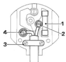
- Only fit 13 Amperes BS1363A approved plugs fitted with the correctly rated fuse (1).
- The cable wire colours, or a letter, will be marked at the connection points of most good quality plugs. Attach the wires to their respective points in the plug (see below). Brown is for Live (L) (2) and Blue is for Neutral (N) (4).
- Before replacing the top cover of the mains plug ensure that the cable restraint (3) is holding the outer sheath of the cable firmly and that the two leads are correctly fixed at the terminal screws.
text_image
Technical diagram of a mechanical or electrical component with numbered parts labeled 1 to 4
Never use a light socket. Never connect the live (L) or neutral (N) wires to the earth pin marked E or 12
For 115 V units with a power rating exceeding 1500 W, we recommend to fit a plug to BS4343 standard.
Using an extension cable
If an extension cable is required, use an approved extension cable suitable for the power input of this machine (see technical data).
The minimum conductor size is 1.5 mm ^4 .
When using a cable reel, always unwind the cable completely.
Also refer to the table below.
| Conductor size (mm2) Cable rating (Amperes) | |
| 0.75 6 | |
| 1.00 10 | |
| 1.50 15 | |
| 2.50 20 | |
| 4.00 25 | |
| Cable length (m) | |
| 7.5 15 25 30 45 60 | |
| Voltage Amperes Cable rating (Amperes) | |
| 230 0 - 2.0 6 6 6 6 6 | 6 |
| 2.1 - 3.4 6 6 6 6 | 6 6 |
| 3.5 - 5.0 6 6 6 | 6 10 15 |
| 5.1 - 7.0 | 10 10 10 10 15 15 |
| 7.1 - 12.0 | 15 15 15 15 20 20 |
| 12.1 - 20.0 | 20 20 20 20 25 |
Assembly and adjustment

- Prior to assembly and adjustment always unplug the tool.
- For optimum performance of your saw, it is of vital importance to follow the procedures in the paragraphs below.
Unpacking your saw (fig. A1)
- Remove all parts from the package, except for the arm (12).
- Lock the arm using the mitre clamp lever (10).
- Tilt the carton and pull out the arm.
- Tilt the assembly to upright position.

The machine must be level and stable at all times.
Mounting the height adjustment crank (fig. A1)
- Mount the height adjustment crank (11) on top of the column (8) using the cross head screw.
Mounting the roller head assembly (fig. A1, A2 & B)
- Rotate the height adjustment crank (11) in the direction of the + to raise the arm (12) as far as it will go (fig. A1).
- Remove the two Allen screws (24) and remove the end-cap (13) (fig. B).
- Roughen the bearing tracks (25) using a steel wool pad and remove any dust with a dry cloth (fig. B).
• Make sure that the riplock (15) is released (fig. A2). - Carefully insert the bearings (26) of the roller head assembly (22) into the bearing tracks.
- Move the roller head in the bearing tracks to check that it runs smoothly.
- Check that the riplock will lock and release the roller head as required.
- Replace the end-cap (13) immediately.
Mounting the cable support and cable clamp (fig. A2 & C)
- Mount the cable support (23) in the hole (27).
- Fit the cable (28) at the rear of the arm using the cable clamp (29).

Allow for the arm movement in horizontal and vertical direction.
The saw table (fig. D1 - D5)
Mounting the table supports (fig. D1)
The table supports are mounted using M10 x 16 bolts and corresponding nuts and with a D8 Belleville washer at the front, but not at the rear.
- Mount the support (30) to the left-hand side of the table base.
- Mount the support (32) to the right-hand side of the table base.
- Do not yet tighten the bolts.
Adjusting the table supports using the arbor (fig. A1 & D2)
- Release the bevel clamp lever (19) and pull out the bevel latch (21) (fig. D2).
- Turn the motor to vertical position and lock it using the bevel latch (21) and the bevel clamp lever (19).
- Loosen the mitre clamp lever (10) (fig. A1) to rotate the arm until the arbor (33) is right above the outer front edge of one of the table supports.
- Carefully lower the arm until the arbor just touches the table support and tighten the corresponding nut of the table support manually.
- Repeat this procedure at the rear edge and for the other table support.
- Check again using the motor arbor.
- Firmly tighten all fasteners.
- Bring the arm back to the central position and lock it.
Adjusting the central table support (fig. D3)
- Place a level over the two table supports (30) and (32).
- Loosen the bolts (34) in the central table support (35).
- Adjust the central table support using an Allen key until it just touches the level.
- Firmly tighten all fasteners.
Mounting the fixed table section (fig. D1 & D4)

The standard position of the table top sections is shown in figure D4.
Depending on the required depth of cut, the fence (6) can also be positioned between the strips (18).
- Place the fixed table section (4) on the table base as shown and check that the holes in the middle locate over the adjustment screws in the central table support.
- Use the M8 x 30 bolts and D8 flat washers at the top and D8 Belleville washers at the bottom.
- Manually tighten all bolts in the fixed table section (4) except for the five front bolts and the bolt in the large central hole.
- Place the fence (6) and the strips (18) on the table base (31) (fig. D1).
- Mount the table clamps (7) (fig. D4) to the rear of the table supports (30) & (32) (fig. D1).
- Tighten the table clamps.
- Firmly tighten all bolts in the table top.
Mounting the table extension (fig. D5 & D6)
- Fit the support strips (36) and (37) to the lower left-hand surface of the fixed table section (4) (fig. D5).
- Place the table extension (5) on the protruding table support strips (fig. D6).
- Check that both tables are flush and mount the table extension via the slotted holes using the bolts, washers and nuts provided (fig. D6).
- Tighten the two corresponding front bolts in the fixed table section (4).

Both tables must be flush at the rear.
The saw blade (fig. E1 - E6)
Mounting the saw blade (fig. E1)

- The teeth of a new blade are very sharp and can be dangerous.
- The direction of rotation is indicated by the arrow on the motor.
- Hold the arbor using the Allen key (38) supplied with the machine and remove the arbor nut (39) by turning clockwise with the multifunctional spanner (40).
- Mount the blade (41) between the outer flange (42) and the inner flange (43) making sure that the lower teeth point to the rear of the machine.

Make sure that the ring (44) of the arbor nut (39) is against the outer flange (fig. E1).
- Tighten the arbor nut (39) by turning counterclockwise.
Checking that the arm is parallel to the table top (fig. A2, D3 & E2)
- Tighten the riplock (15) with the blade in front position (fig. A2)
- Lower the blade until it only just touches the table top (4) (fig. E2).
- Release the levers (9) and (10) (fig. A1).
- Swing the arm so that the blade skims the table top (4) across its width.
- If required, adjust the front adjusting bolt (34) (fig. D3).
- Repeat this procedure with the blade in rear position and adjust the rear bolt if required.
Checking that the blade is perpendicular to the table top (fig. A2 & E3)
- Bring the arm back to central position and tighten the riplock (15) (fig. A2).
- Place a steel square (45) against the blade body (fig. F3).
- If adjustment is required, proceed as follows:
- Remove the bevel pointer disk (46) by loosening the two screws (47).
- Loosen all three Allen screws that will be exposed in this way.
- Place an Allen key in the motor arbor and tap until the blade is flat against the square.
• Firmly tighten all fasteners.

It is particularly important to tighten the central Allen screw.
- Replace the bevel pointer disk (46).
Checking that the crosscut travel is perpendicular to the fence (fig. E4 & E5)
- Lock the blade in front of the fence (fig. E4).
- Place a square (45) on a piece of board and against the fence and just touching the blade as shown.
- Unlock the riplock, pull the blade towards you to check that the blade traverses parallel to the square.
- If adjustment is required, proceed as follows:
- With the mitre latch lever (9) engaged in 0^ position, release the mitre clamp lever (10) (fig. E5).
- Loosen the locknuts (48) on each side of the arm (fig. E5).
- To adjust the arm to the left, loosen the stud on the righthand side of the arm and tighten the opposite stud.
- To adjust the arm to the right, loosen the stud on the lefthand side of the arm and tighten the opposite stud.
- Proceed in small steps and check the adjustment after each step with the levers (9) and (10) engaged.

Do not overtighten the studs.
- Tighten the locknuts (48).
Checking that the blade is perpendicular to the fence (fig. E6)
- Unlock the yoke clamp lever (49) press the yoke latch (50).
- Rotate the motor through 90^ as shown.
- If the motor shows a certain play, tighten the nut (51).
- Place the blade against the fence and check that it is parallel to the fence.
- If adjustment is required, proceed as follows:
- Loosen the two bolts (52) installed crosswise under the yoke.
- Insert the Allen key into the motor arbor.
- Adjust the blade position and tighten the bolts (52).
Mounting and adjusting the blade guard assembly (fig. F1 - F5)
The blade guard (3) is a multifunctional assembly which offers the following safety features (fig. F1):
- Upper guard (53) (fig. G1) and spring held rear guard (54) (fig. F2) for full blade protection.
- Dust extraction adapter (55) for cross and rip cutting.
- Anti-kickback fingers (56) for use in ripping mode.
- Adjustable finger guard (57) for use when cross-cutting.
-
Riving knife (58) to prevent the workpiece binding on the blade when ripping.
-
Release the bevel clamp lever (19) and pull out the bevel latch (21) (fig. D2) to tilt the motor as shown for optimum access (fig. F3).
- Remove the guard retaining wing nut (59) and washer (60) (fig. F3).
- Loosen the locking screw (61) and turn the retaining bracket (62) anticlockwise until the spring held rear guard (54) can be lifted off its support lug (63) (fig. F2).
- Unhook the two springs (64) at the top only.
- Rotate the unhooked rear blade guard (54) as shown (fig. F2).
- Lower the guard assembly over the blade (fig. F3).
- Secure the guard assembly using the wing nut (59) and washer (60) (fig. F3).
- Bring the spring held rear blade guard (54) and the retaining bracket (62) into their original position (fig. F2).
- To remove the guard assembly, proceed in reverse order.

The teeth of a new blade are very sharp and can be dangerous.
Adjusting the guard assembly controls (fig. F2 - F5)
Adjusting the riving knife for ripping
- Loosen the two knobs (65) and slide the riving knife (58) down until the tip is approximately 10 mm from the table top (fig. F2 & F4).

The riving knife should be correctly set; the distance between the toothed rim and the riving knife (58) should be 1-3 mm (fig. F4).
Adjusting the anti-kickback fingers for (bevel) ripping (fig. F5)
- Loosen the knob (66) and lower the bracket (67) until the hold down spring (68) just touches the surface of the workpiece.
- The tips of the anti-kickback fingers (56) should now be 3 mm below the surface of the workpiece and the angle should now be as shown in figure F5.
- For bevel ripping, loosen the Allen screw (69) and set the anti-kickback fingers to the required angle.
Adjusting the riving knife, finger guard and anti-kickback fingers for cross-cutting (fig. F2)
- For cross-cutting, adjust the riving knife and anti-kickback fingers up and out of the way.
- Loosen the lever (70) to position the finger guard (57) just above the workpiece and lock the lever (70).
Scale adjustments (fig. G1 - G5)
Rip scale
Ripping can be done with the motor in two positions. Each mode requires its own direction of feed:
Position Direction of feed
- In-rip from right to left (fig. G1)
- Out-rip from left to right (fig. G2)
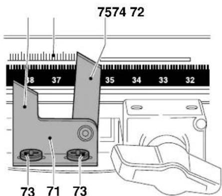
The pointer (71) indicating the ripping width on the rip scale (72) is adjustable (fig. G3):
- Place the fence in rearmost position.
- Place a board of 24 mm against the fence.
- Unlock the yoke clamp lever (49), press the yoke latch (50) (fig. H1) and position the motor in out-rip position (fig. G1).
-
Move the yoke assembly along the radial arm until the blade just touches the edge of the material.
-
Loosen the two screws (73) and move the pointer (71) until the edge of the out-rip pointer (74) lines up with the known width of the board on the lower scale (fig. G3).
- Tighten the two screws (73) (fig. G3).
- Place the motor in in-rip position.
- Raise the guard to allow the blade to rest against the face of the fence.
- The in-rip pointer (75) should now line up with the zero position in the upper scale. Adjust if necessary (fig. G3).
Bevel scale (fig. G4)
- Check that the bevel scale (20) reads 0^ when positioned for a vertical cut.
- If required, loosen the screws (47) and adjust the pointer to 0^ .
- Check that the mitre scale (76) reads 0^ when positioned for a vertical cut.
- Adjust the pointer (77) to register 0^ using the screw (78).
The mitre scale has preset positions at 45^ left and right and at 0^ .
Yoke travel stop (fig. A2, H1 & H2)
The yoke travel stop (14) must be adjusted to avoid that the bearings on the yoke assembly hit the rear limit of the bearing tracks (fig. A2).
- Push the yoke assembly as far as it will go, pull it forwards approx. 5 mm and lock it the using the riplock (15) (fig. A2).
- Adjust the yoke travel stop (14) by slackening the nuts (79) in the front slot (80) until the rubber stop (81) butts against the back of the riplock housing (fig. H1).
- Tighten the nuts (79).

When cross-cutting, tighten one nut in the front slotted hole and one in the rear slotted hole (fig. H2).
Mounting the return spring (fig. J)
- Mount the return spring (82) behind the yoke travel stop (14) using the corresponding bolts and attach the end of the cable to the riplock (15) using the screws (83).
Consult your dealer for further information on the appropriate accessories.
Instructions for use

- Always observe the safety instructions and applicable regulations.
- Ensure the material to be sawn is firmly secured in place.
- Apply only a gentle pressure to the tool and do not exert side pressure on the saw blade.
- Avoid overloading.
- Install the appropriate saw blade. Do not use excessively worn blades. The maximum rotation speed of the tool must not exceed that of the saw blade.
- Do not attempt to cut excessively small pieces.
- Allow the blade to cut freely. Do not force.
- Allow the motor to reach full speed before cutting.
- Make sure all locking knobs and clamp handles are tight.
- Never run the machine without the guards in place.
- Never lift the machine by the table top.
- Always refer to figure K to check the fence position and type.
The attention of UK users is drawn to the “woodworking machines regulations 1974” and any subsequent amendments.
Switching ON and OFF (fig. A1)
The ON/OFF-switch of your radial arm saw offers multiple advantages:
- no-volt release function: should the power be shut OFF for some reason, the switch has to be deliberately reactivated.
-
motor overload protection device: in case of motor overload, the power supply to the motor will be cut OFF.
-
I = ON The tool now works in continuous operation.
- O = OFF
Making a trial cut (fig. A1)
- With the mitre latch lever (9) engaged, lock the mitre clamp lever (10) so that the blade is positioned for a straight 0^ cross-cut.
- Release the riplock (15) and push the yoke assembly back until the blade is behind the fence.
- Lower the arm until the blade almost touches the table top.
- Place the workpiece against the front of the fence.
- Switch ON and lower the arm to allow the blade to cut a shallow groove in the table surface.
- Pull the blade towards you so that it cuts a vertical slot in the wooden fence and through the workpiece.
- Return the blade back to rest position and switch OFF.
- Check that the cut is a true 90^ in all planes and adjust if required.
Basic Saw Cuts (fig. K1 - K5)

The teeth of a new blade are very sharp and can be dangerous.
Cross-cutting (fig. A1 & K1)
- Set the radial arm at right angles to the fence.
- Engage the mitre latch lever (9) in 0^ position and tighten the mitre clamp lever (10) (fig. A1).
- Lower the blade.
- Adjust the finger guard so that it just clears the workpiece.
- If there is no slot in the table top, cut one as described above.
- Hold the workpiece against the fence, keeping your fingers well away from the path of the blade.
- Switch ON and slowly pull the blade though the fence and the workpiece.
- Return the blade to rest position and switch OFF.
Mitre cuts (fig. A1 & K3)
- Release the mitre latch lever (9) and the mitre clamp lever (10) (fig. A1).
- Swing the arm to the required angle on the mitre scale.
- For 45^ left or right, engage the mitre latch lever (9) and lock with the mitre clamp lever (10).
- For intermediate angles, use the mitre clamp lever only.
• Proceed as for cross-cutting.

In the case of left-hand mitre, you may have to slide the fence and the strips to the left.
Bevel cuts (fig. A1, D2 & K2)
- Set the arm as for a 0^ cross-cut.
- Raise the blade well above the table surface.
- Release the bevel clamp lever (19) and pull out the bevel latch (21) (fig. D2).
- Tilt the motor to the required angle on the bevel scale (20) (fig. A1).
- For 90^ or 45^ right, engage the bevel latch (21) and lock with the bevel clamp lever (19).
- For intermediate angles, use the bevel clamp lever only.
• Proceed as for a vertical cross-cut.
Ripping (fig. K5, F2, G1 & G2)
The motor can be locked in in-rip or out-rip position as shown in figures G1 & G2 to adapt the machine to narrow and wide workpieces respectively.
- Lock the yoke in pulled out position using the riplock.
- Release the yoke clamp lever (49) and press the yoke latch (50) to rotate the motor to the appropriate position until it locks in place (fig. G1).
- Tighten the yoke clamp lever (49) and position the fence accordingly.
-
Position the yoke along the arm for the desired width of cut, using the rip scale (72) and lock it in position using the riplock.
-
Adjust the blade guard as described above and turn the dust extraction adaptor (55) away from your face (fig. F2). Remember that ripping requires the use of the riving knife (58) and the anti-kickback fingers (56) (fig. G2).
- Slowly feed the workpiece into the blade, keeping it firmly pressed onto the table and against the fence. Allow the teeth to cut and do not force the workpiece through the blade. The blade speed should be kept constant.

Always use a push stick.
Bevel ripping
- Set the machine in the bevel crosscut position.
- Rotate the yoke into rip position.
- Position the yoke for the correct ripping width.
- Angle the anti-kickback fingers so that they will be flat on the workpiece and lower the riving knife.
• Proceed as for ripping.
Compound mitre (fig. K4)
This cut is a combination of a mitre and a bevel cut.
- Set the required bevel angle.
- Swing the arm to the required mitre position.
• Proceed as for mitre cuts.
Always switch OFF the tool when work is finished and before unplugging.
Coving/hollowing
Your radial arm saw can be used for a wide variety of advanced applications, such as coving/hollowing.
- Tilt the blade to the required angle, rotate the yoke beneath the arm and position the blade above the workpiece where required. Remove the workpiece and lower the blade to make a shallow cut. Lower the anti-kickback fingers as for bevel ripping. Keeping the workpiece against the fence, proceed as for ripping.

Make shallow cuts only!

Dust extraction (fig. F2)
The machine is provided with a dust extraction adaptor (55).
- Whenever possible, connect a dust extraction device designed in accordance with the relevant regulations regarding dust emission.
- When cross-cutting, position a dust collection chute (option) behind the line of cut.
Optional Accessories

Prior to assembling any accessories always unplug the machine.
Shaping/moulding head
The shaping/moulding head is used to provide your work with a professional finish.
Mounting the shaping/moulding head (fig. L1 - L3)
- Remove the blade guard assembly and the blade.
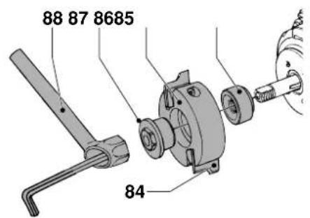
- Fit the cutters (84) to the shaping/moulding head (85) making sure that they are installed in the same way (fig. L1).
- Mount the special spacer (86) supplied with the shaping head onto the arbor.
-
Put the shaping head onto the arbor as shown and lock it with the clamping nut (87) using the box spanner (88) available as an option.
-
Tilt the motor until the shaping head is in horizontal position.
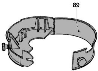
- Mount the shaping head guard (89) (fig. L2) as shown and adjust it to the required depth of cut (fig. L3).
Shaping/moulding
- Place the shaping/moulding head over the fence. The protruding section corresponds to the cut that will be made.
Certain applications may require to divide the fence into two sections and to place the shaping/moulding head between them. In that case, the fence must be replaced when the saw is used for ordinary applications again.

Always use a push stick.
- Feed the material firmly and evenly along the fence from the right.
Rebating
- Use straight-edged cutters.
• Proceed as for shaping/moulding. - For bevelled rebate cutting, tilt the motor to the required angle.

For wider rebates, use the dado head together with the guard of the shaping/moulding head.

Refer to the instructions pertaining to the use of the dado head.
The Dado head (fig. F1, M1 & M2)
There are two types of dado heads available. Figure M1 shows the standard quality dado head and figure M2 shows the long life premium quality model.

Sharp edges.
Mounting the dado head
- Remove the blade guard assembly and the blade.
- Mount the spacer (90) onto the arbor with the narrower side towards the motor.
- Mount the cutter blades (91) with the required number of intermediate blades (92) between them together with a combination of shims (93) to achieve the required width of cut.
- Secure the dado head using the standard arbor nut (39) (fig. E1).
- Remove the riving knife and its support bracket from the blade guard assembly and mount the guard.
- Lower the dado head into position for the depth of cut required.
Using the dado head
In crosscut or mitre position
- Adjust the anti-kickback fingers up and out of the way.
- Adjust the finger guard correctly.
- In ripping position
- Adjust the anti-kickback fingers correctly.
Disc sanding and drum sanding (fig. M2, N1 & N2)
Two sanding attachments are available for cuts requiring sanding at any angle. Both can be used as follows:
- moving the workpiece along the stationary accessory
- moving the accessory along the clamped workpiece
- Remove the blade guard assembly and the blade.
- Return the outer flange (42) (fig. N1).
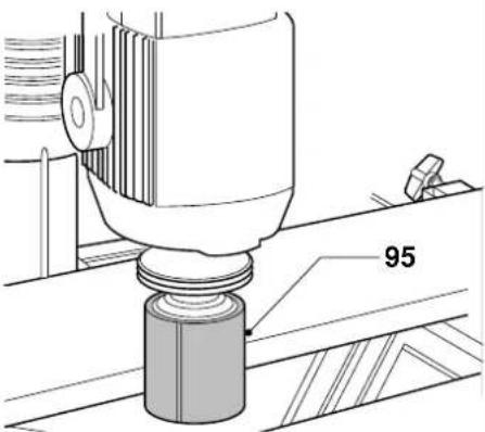
- Mount the disc sander (94) or the sanding drum (95) (fig. N2) directly onto the arbor.
Disc sanding (fig. N1)
• Always use the downward (right-hand side) of the disc.
- When using the disc sander (94) for horizontal sanding, the shaping head guard (89) (fig. N2) should be mounted and adjusted so that the sanding disc is just clear of the underside of the guard.
Drum sanding (fig. N2)
- When drum sanding, always feed your material against the rotation of the drum sander.
The router bracket (fig. E1, O1 - O3)
The router bracket (96) allows you to attach a Elu router (MOF96, MOF131, MOF177 or OF97) to your machine, thus extending its versatility to accurate, decorative woodworking (fig. O1).
Mounting the router bracket
- Remove the blade guard assembly and the blade.
- Position the router bracket (96) over the end of the arbor as shown in figure O1 and secure it with the wing nut (59).
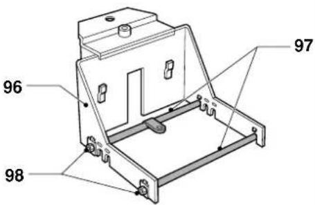
- Replace the guide rods of the parallel fence of your router by the support bars (97) supplied with the attachment:
- Use the small diameter bars for MOF96 (fig. O2)
- Use the large diameter bars for MOF131/MOF177/OF97 (fig. O3).
- Tighten the locking screws (98).

Always make sure your router is properly centred on the bars and secured in the bracket.
Routing (fig. A1 & E1)
The router can be set to the required angle and pulled across the workpiece using the handle (2) in figure A1 or guided along the stationary cutter.
- Check that the router bracket is mounted rigidly.
- If required, fit the outer flange (42) in figure E1 on the arbor and clamp the router bracket against the motor using the arbor nut (39) in figure E1. Do not overtighten the arbor nut.

Always feed the workpiece against the rotating cutter.

Also refer to the instruction manual of your Power Tool.
Drilling/boring (fig. P)
The threaded location hole (99) accepts the optional 10 mm or 3/8" drill chuck which turns your saw into a versatile radial drilling unit. This option is particularly useful for preparing material for dowels.
- Remove the blade guard assembly and the blade.
- Pivot away the cover (100).
- Fit the drill chuck (101) directly into the threaded location hole (99).
Mitre fences (fig. Q1 & Q2)
Mitre fences (102) are available to extend and speed up the angle cutting facility (fig. Q1).
- Replace the standard fence by the mitre fences (102).
- Guide the saw blade between the two fence sections (fig. Q2).
Sabre sawing (fig. R1 - R3)
Mounting the sabre saw
By mounting the sabre saw attachment (103) in the motor arbor, your machine can be turned into a radial sabre or jigsawing machine (fig. R3).
- Remove the blade guard assembly and the blade.
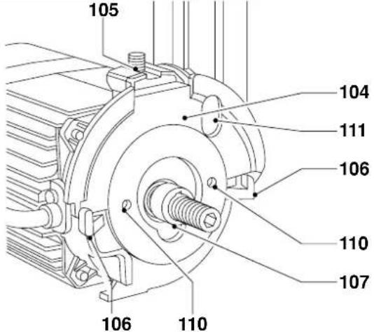
- Mount the plastic rear spacer (104) onto the motor arbor with the retaining lug (105) over the guard retaining screw and the flat front surface slotted behind the guard retaining lugs (106) (fig. R1).
-
Place the special spacer (107) onto the spindle.
-
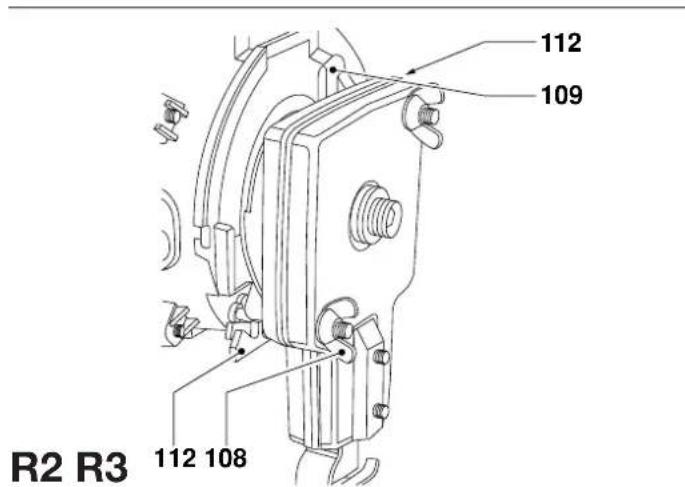
Loosen the two wing nuts (108) in the front of the sabre saw to allow the two angled retaining struts (109) to protrude from the rear (fig. R2).
- Place the sabre saw onto the motor arbor and locate the two location pins into the holes (110) provided in the spacer (fig. R1).
- Push the top right-hand retaining strut (109) through the hole in the spacer (111) and turn to locate the flat angle piece behind the lug (112).
- Locate the lower one in the same way and tighten the wing nuts.
- Place the standard arbor nut onto the spindle and tighten it. Recheck the tightness of the wing nuts.
- Fit the saw blade (113) onto the slot in the bottom of the shaft with the teeth towards the operator. The shaft has a small grub screw (114) in either side for clamping and centralizing the blade (fig. R3).
Using the sabre saw (fig. R3)
Positioning of the sabre saw depends on the requirements of the job. There is a small hole (115) in the fixed table to allow the blade to pass through the table, or in some cases the position could be as with the drum sander.
- Remove the table fence and substitute it with wooden spacers (20 mm) and then position the blade (teeth forwards) just behind the front fixed table.
- Before starting to saw, ensure the sawfoot is lowered to prevent any tendency for the material to lift.
Traverse control (fig. A1, J, S1 - S3)
The traverse control (116) guarantees optimum results in applications where a consistent, even feed rate is important.
Mounting the traverse control
- Remove the return spring (82) in figure J.
- Remove the yoke travel stop (14) in figure A1.
- Mount the rear flat bracket (117) and the yoke travel stop as shown in figure S2.
- Loosen the grub screw (118) in the knurled knob (119) using an Allen key and unscrew the knurled knob (fig. S3).
- Loosen the grub screw (120) in the rear support (121) and pull the support off the rod.
• Pass the cylinder (122) through the cylinder clamp (123) (fig. S1). - Position the cylinder clamp (123) over the riplock (15) and tighten the grub screws in each side of the mounting (124).
- Reassemble the rear support (121) and the knurled knob (119) and tighten all screws (fig. S3).
- Position the rear support (121) as shown (fig. S3) and tighten the grub screw (120).
- Push the roller head to the rear and position the cylinder in its clamp (123) as far to the rear as possible. The end of the rod should not touch the bleed bolt in the rubber bellows, when the bellows (125) are compressed. Check the position by pressing the bleed bolt.
- Tighten the screw (126) in the cylinder clamp.
- Set the traverse speed using the knurled knob (119).
Bleeding the traverse control
After refilling or replacing the oil in the traverse control, the air must be expelled from the system.
- Remove the unit from the machine and with the piston fully extended and turned downwards, clamp the unit in a vertical position.
- Remove the plug at the rear end of the bellows (125). Hold the bellows to avoid spilling the oil.
- Refill the bellows completely with hydraulic oil Castrol 210 NRL25 or equivalent using a funnel or an oil syringe.
- Replace the filler plug and tighten it one turn.
- Slightly press the bellows until some oil escapes from the filler plug.
- Tighten the filler plug with a wrench and reinstall the unit.
Legstand (fig. T)
The legstand (127) consists of four legs (128), four traverse rails (129) and four top traverse rails (130). The latter are the same size as the base frame of your radial arm saw.
- Assemble the legs and traverse rails as shown.
- Tighten the bolts.
- Secure the saw to the top.
Maintenance
Your DeWALT Power Tool has been designed to operate over a long period of time with a minimum of maintenance. Continuous satisfactory operation depends upon proper tool care and regular cleaning.
- Replace the fixed table top and fence when worn.

Lubrication
Your Radial Arm Saw requires no additional lubrication.

Never grease the arm tracks or bearings.

Cleaning
- Regularly clean the armtracks. Remove the end-cap and the yoke to do so. Also remove dust from the bearings.
- Keep the table top clean at all times. Never use your hands to wipe off the dust.

Unwanted tools and the environment
Take your tool to an authorized DeWALT repair agent where it will be disposed of in an environmentally safe way.
GUARANTEE
• 30 DAY NO RISK SATISFACTION GUARANTEE •
If you are not completely satisfied with the performance of your DEWALT machine, simply return it within 30 days, complete as purchased, to a participating Dealer, or an authorized DEWALT repair agent, for a full refund or exchange. Proof of purchase must be produced.
• ONE YEAR FREE SERVICE CONTRACT •
If you need maintenance or service for your DEWALT machine, in the 12 months following purchase, it will be undertaken free of charge at an authorized DEWALT repair agent. Proof of purchase must be produced. Includes labour and spare parts for Power Tools. Excludes accessories.
- ONE YEAR WARRANTY •
If your D=WALT product becomes defective due to faulty materials or workmanship within 12 months from the date of purchase, we guarantee to replace all defective parts free of charge or, at our discretion, replace the unit free of charge provided that:
• The product has not been misused.
• Repairs have not been attempted by unauthorized persons.
• Proof of purchase date is produced.
This guarantee is offered as an extra benefit and is additional to consumers statutory rights.
For the location of your nearest authorized DEWALT repair agent, please use the appropriate telephone number on the back of this manual.
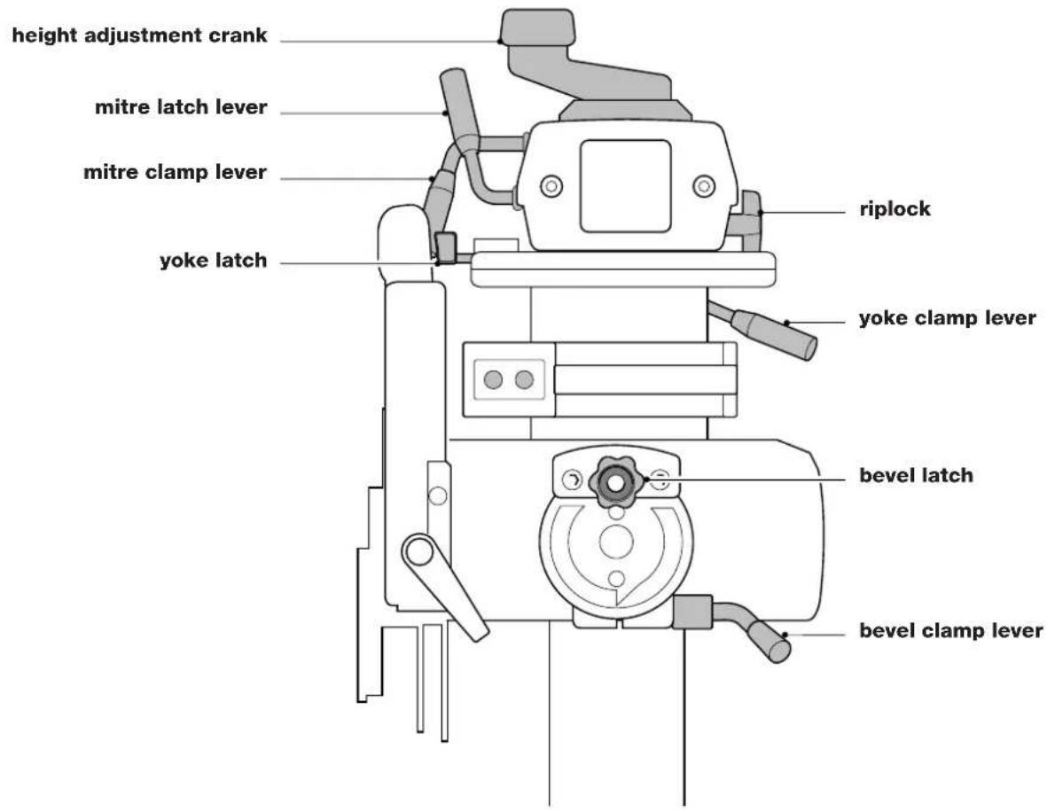
QUICK REFERENCE CHART
text_image
height adjustment crank mitre latch lever mitre clamp lever yoke latch riplock yoke clamp lever bevel latch bevel clamp leverSIERRA CIRCULAR DE BRAZO DW720
¡Enhorabuena!
Director Engineering and Product Development
Horst Großmann
X. fopsmann
L'emballage contient:
Perçage/forage (fig. P)
Sagomature/modanature
RADIAALARMZAAG DW720
Gefeliciteerd!
| Cert. No. | |
| BM 9511442.01 |
Director Engineering and Product Development
Horst Großmann
X. fopman
Director Engineering and Product Development
Horst Großmann
X. fopsmann
Director Engineering and Product Development
Horst Großmann
X. Jopsmann
15 Tire as chaves de aperto
- Aperte as contra-porcas (48).
Director Engineering and Product Development
Horst Großmann
X. fopsmann
| Cert. No. | |
| BM 9511442.01 |
Director Engineering and Product Development
Horst Großmann
X. fopsmann
RADYAL KOL TESTERESİ DW720
Tebrikler!
Mounting the height adjustment crank (şekil A1)
- Mount the height adjustment crank (11) on top of the column (8) using the cross head screw.