
FX-E2MS - String Trimmer Fuxtec - Free user manual and instructions
Find the device manual for free FX-E2MS Fuxtec in PDF.


| Product type | Brush cutter / Grass trimmer |
| Model | FX-E2MS |
| Brand | Fuxtec |
| Power supply | Lithium-ion battery 40 V |
| Weight (without battery) | 4.55 kg |
| Rotation speed | 4500 - 6000 rpm |
| Cutting diameter (trimming head) | 350 mm |
| Cutting diameter (3-tooth blade) | 255 mm |
| Line thickness | 2 mm |
| Sound pressure level (LpA) | 81 dB(A) |
| Guaranteed sound power level (LwA) | 91.2 dB(A) |
| Number of speeds | 2 (I and II) |
| Main functions | Grass cutting, edge trimming, variable speed, interchangeable head (line or 3-tooth blade), automatic and manual line feed |
| Safety | Safety switch, cutting guard, automatic stop, battery lock |
| Maintenance and cleaning | Dry cleaning with brush or cloth, do not use water, remove grass residues, keep contacts clean |
| Spare parts and repairability | Use only original parts, repair by a qualified specialist |
| Manufacturer | FUXTEC GmbH, Kappstrasse 69, 71083 Herrenberg, Germany |
| Warranty | Manufacturer warranty according to conditions |
Frequently Asked Questions - FX-E2MS Fuxtec
User questions about FX-E2MS Fuxtec
0 question about this device. Answer the ones you know or ask your own.
Ask a new question about this device
Download the instructions for your String Trimmer in PDF format for free! Find your manual FX-E2MS - Fuxtec and take your electronic device back in hand. On this page are published all the documents necessary for the use of your device. FX-E2MS by Fuxtec.
USER MANUAL FX-E2MS Fuxtec
natural_image
Illustration of a robotic arm with articulated joints and a connecting rod against a black background (no text or symbols)
natural_image
Orange icon of a person reading a book (no text or symbols)
natural_image
Icon of a hand pointing at an open book with horizontal lines representing text (no actual text or symbols)Inhalt
DEUTSCHE VERSION 9
ENGLISH VERSION....36
VERSION FRANCAISE 64
-
Introduction and safety 36
-
Use and treatment of the power tool 38
-
Use and handling of the cordless tool....38
-
Safety instructions for the brush cutter 39
-
Safety instructions for the charger 41
-
Safety Instructions for Li-Ion Batteries.... 41
-
Presentation 42
-
Assembly......45
-
Attaching the shoulder strap....48
-
Working with the brush cutter....52
-
Trimming / cutting grass....54
-
Use the automatic feeding 56
- Manual feeding of the thread 57
- Use the 3-teeth blade....57
- Working Instructions....58
- Wind a new thread....58
- Maintenance and care....61
- Disposal 61
- Technical Data 62
- EU Declaration of Conformity 63
VERSION FRANCAISE 64
natural_image
Mechanical assembly diagram showing a bracket with a hammer and arrow indicating motion (no text or symbols)Montage Rundgriff
natural_image
Diagram of a mechanical device with a cylindrical component inserted into a housing (no text or symbols visible)natural_image
Mechanical assembly diagram showing a pipe joint with a bracket and handle (no text or symbols)natural_image
Mechanical assembly diagram showing a clamp or bracket with metal rods and bolts (no text or symbols)Installation des Schutzschildes
natural_image
3D technical illustration of a mechanical assembly with internal components and a base component (no text or symbols)natural_image
Close-up of a hand holding a white cylindrical pipe with attached clamps and fittings (no text or symbols visible)natural_image
Illustration of a hand turning a mechanical device into a motor housing (no text or symbols visible)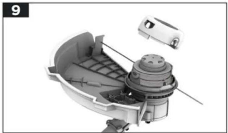
natural_image
Cutaway view of a mechanical device showing internal components and housing (no text or symbols visible)natural_image
3D rendered mechanical component with internal structure and housing, no visible text or symbolsnatural_image
Cross-sectional diagram of a mechanical device with internal components and an arrow indicating direction (no text or symbols)natural_image
Exploded view diagram of a mechanical assembly with no visible text or symbolsnatural_image
Cutaway view of a mechanical device showing internal components and housing (no text or symbols)natural_image
Line drawing of a person using a long-handled manual lawn power tool in a grassy field (no text or symbols)natural_image
Close-up of a mechanical component with directional arrows indicating movement or force (no text or symbols visible)natural_image
Line drawing of a person using a long-handled manual lawn brush in a grassy field (no text or symbols)natural_image
Mechanical device with two upward and downward arrows indicating motion or force (no text or symbols)natural_image
3D technical illustration of a mechanical component with directional arrows indicating flow or movement (no text or symbols)natural_image
Close-up of a mechanical component with a dome-shaped top and internal structure (no visible text or symbols)Recycling raw materials instead of waste disposal.
- Technische Daten
Hereby we declare that the above mentioned machine meet the essential safety and health requirements of the above stated EC directives. Any manipulation or change of the machine not being explicitly authorized by us in advance renders this document null and void.
22. Introduction and safety
Never allow children or persons unfamiliar with these instructions to use the garden device. Children should be supervised to ensure that they do not play with the appliance.
Intended use
This garden device is designed for trimming and cutting grass edges and smaller grass and grass areas in the private sector. It is not suitable for trimming
bushes, hedges, and shrubs. The device must be used following the descriptions
and safety instructions are given in this user manual. Any other use is not intended. Unauthorized use will invalidate the warranty and override any responsibility on the part of the manufacturer. The user is liable for all damages to third parties and their property. Operate the device only in the technical condition prescribed and delivered by the manufacturer. Unauthorized modifications to the device exclude the manufacturer's liability for any resulting damage.
General safety instructions for power tools
WARNING!
Read all safety notices and instructions. Failure to follow the safety instructions and instructions can cause electric shock, fire, and/or severe injury.
Keep all safety notes and instructions for future reference.
The term power tool used in the safety instructions refers to mains operated power tools (with power cord) and cordless power tools (without power cord).
Workplace Safety
- Keep your work area clean and well lit. Clutter or unlit work areas can lead to accidents.
- Do not work with the power tool in explosive environments containing flammable liquids, gases, or dust. Power tools produce sparks that can ignite the dust or fumes.
- Keep children and other persons away while using the power tool. If distracted, you may lose control of the device.
Electrical Safety
- The plug of the power tool must fit into the socket. The cap must not be changed in any way. Do not use adapter plugs together with grounded power tools. Unchanged plugs and suitable sockets reduce
the risk of electric shock.
- Avoid physical contact with grounded surfaces such as pipes, heaters, stoves, and refrigerators. There is an increased risk of electric shock if your body is grounded.
- Keep power tools away from rain or moisture. The penetration of water into a power tool increases the risk of electric shock.
- Do not use the cable to carry or hang up the power tool or to pull the plug from the socket. Keep the cord away from heat, oil, sharp edges, or moving parts. Damaged or tangled cables increase the risk of electric shock.
- If you use a power tool outdoors, only use extension cables that are suitable for outdoor use. The use of an extension cable ideal for outdoor use reduces the risk of electric shock.
- If you use a power tool outdoors, only use extension cables that are suitable for outdoor use. The use of an extension cable ideal for outdoor use reduces the risk of electric shock.
Safety of Persons
- Be alert, pay attention to what you are doing, and use common sense when working with a power tool. Do not use a power tool if you are tired or under the influence of drugs, alcohol, or medication. A moment of inattention while utilizing the power tool can cause serious injury.
- Wear personal protective equipment and always protective goggles. Wearing personal protective equipment, such as dust mask, non-slip safety shoes, safety helmet or hearing protection, depending on the type and use of the power tool reduces the risk of injury.
- Avoid unintentional commissioning. Make sure that the power tool is switched off before connecting it to the power supply and/or battery, picking it up or carrying it. If you have your finger on the switch when carrying the power tool or if you connect the device to the power supply while it is switched on, this can lead to accidents.
- Remove adjustment tools or wrenches before turning on the power tool. A tool or key that is in a rotating part of the device can cause injury.
- Avoid an abnormal posture. Make sure you have a secure footing and keep your balance at all times. This allows you to better control the power tool in unexpected situations.
- Wear suitable clothing. Do not wear loose clothing or jewelry. Keep hair, clothing, and gloves away from moving parts. Loose clothing, jewelry, or long hair can be caught by moving parts.
23. Use and treatment of the power tool
- Do not overload the device. Use the appropriate power tool for your work. With the right power tool, you will work better and safer in the specified power range.
- Do not use a power tool with a defective switch. A power tool that can no longer be switched on or off is dangerous and must be repaired.
- Unplug the power cord and/or remove the battery before making any adjustments to the device, changing accessories, or putting the device away. This precaution prevents unintentional starting of the power tool.
- Keep unused power tools out of the reach of children. Do not allow persons to use the device which is not familiar with it or have not read these instructions. Power tools are dangerous if they are used by inexperienced persons.
- Maintain power tools with care. Check that moving parts function correctly and do not jam, that parts are not broken or damaged in such a way that the function of the power tool is impaired. Have damaged parts repaired before using the device. Many accidents are caused by poorly maintained power tools.
- Keep cutting tools sharp and clean. Carefully maintained cutting tools with sharp cutting edges jam less and are easier to guide.
- Use power tools, accessories, insertion tools, etc. according to these instructions. Take into account the working conditions and the job to be performed. The use of power tools for applications other than those intended can lead to dangerous situations.
24. Use and handling of the cordless tool
- Charge the batteries only with chargers recommended by the manufacturer. A charger that is suitable for a particular type of battery poses a fire hazard when used with other batteries.
- Only use the batteries provided in the power tools. Using other batteries may result in personal injury and fire hazards.
- Keep the unused battery away from paper clips, coins, keys, nails, screws, or other small metal objects that could cause the contacts to bridge. A short circuit between the battery contacts can cause burns or fire.
- The liquid may leak from the battery if misused. Avoid any contact with it. In case of accidental contact, rinse with water. If the liquid gets into your eyes, seek additional medical attention. Leaking battery fluid may cause skin irritation or burns.
25. Safety instructions for the brush cutter
- For your safety and the safety of others, read this user manual and its safety instructions before using the device. Please keep the user manual and its safety instructions in a safe place for future reference and keep them handy for any use.
- Pass on the operating instructions with the device if there is a change of ownership.
- Persons operating the device must not be under the influence of intoxicating substances (e.g., alcohol, drugs, or medicines).
- Operate the device only in the condition prescribed and delivered by the manufacturer. Unauthorized modifications to the device exclude the manufacturer's liability for any resulting damage.
- Only use the device in daylight or under good artificial lighting.
- Only use the device in dry weather conditions. Keep it away from rain or moisture. The penetration of water into the device increases the risk of electric shock.
- Switch off the device and remove the battery in the following conditions:
♦ if the device is left unattended;
- before checking, cleaning or other work on the device;
♦ if the device starts to vibrate excessively.
Before Use
- Familiarize yourself with the brush cutter and its functions and controls before starting work.
- Check the device for signs of wear or damage before starting up and after a collision.
- Do not use a device whose switch is defective and can no longer be switched on or off.
- Check that all nuts, bolts, and screws are tight to ensure that the device is operated safely.
- Never use a device with damaged or missing parts. Have them repaired or replaced if necessary by a qualified specialist or workshop.
- To reduce the risk of serious injury, never use wire or metal-reinforced thread as cutting thread.
- When working with or on the device, always wear sturdy shoes, long trousers, and the appropriate personal protective equipment (safety goggles, hearing protection, non-slip work gloves, etc.). The wearing of personal protective equipment reduces the risk of injury.
- Do not wear jewelry or loose clothing that could be caught by the grass trimmer. Keep long hair away from the spindle.
- Check the area where the device is being used and remove stones and wires that could be caught by the grass trimmer to avoid endangering people.
- Remove adjustment tools or wrenches before turning on the trimmer. A tool or key that is in a rotating part of the device can cause injuries.
During Operation
- Do not operate the device if persons (especially children) or animals are in the immediate vicinity.
- Interrupt work if you notice that people (especially children) or pets are nearby.
- Always keep hands and feet away from the rotating string or blade, especially when you switch on the brush cutter.
- To prevent injury, still hold the brush cutter parallel to the lawn when switching on.
- Always keep a safe distance during the working process and do not reach into the rotating thread or blade.
- Avoid an abnormal posture. Make sure you have a secure footing and keep your balance at all times. This allows you to better control the brush cutter in unexpected situations and on particularly steep slopes.
- Do not work with the brush cutter in potentially explosive environments containing flammable liquids, gases, or dust. The grass trimmer can produce sparks that can ignite the dust or fumes.
- Exercise particular caution when walking backward. There is a danger of tripping!
- Walk at a walking pace only.
- Never leave the device unattended during work interruptions and store it in a safe place.
After use
- Turn off the device, remove the battery, and then place the device in a safe place.
- Do not store the device within reach of children.
- Make sure that the ventilation slots of the device are free of dirt.
- Spare parts must meet the requirements specified by the manufacturer. Therefore only use original spare parts or spare parts approved by the manufacturer. When replacing the battery, please follow the installation instructions provided and remove the battery first.
- Have repairs carried out exclusively by a qualified specialist or a specialist workshop.
26. Safety instructions for the charger
- Keep the charger away from rain or moisture. The penetration of water into a charger increases the risk of electric shock.
- Keep the charger clean. There is a risk of electric shock from soiling.
- Check the charger, cable, and plug before each use. Do not use the charger if you notice any damage. Do not open the charger yourself and have it repaired only by qualified personnel and only with original spare parts.
Damaged chargers, cables, and connectors increase the risk of electric shock.
- Do not place objects on the charger or place them on soft surfaces. There is a risk of fire.
- Always check that the mains voltage corresponds to the voltage indicated on the charger's nameplate.
- Never use the charger if the cable, plug, or the device itself is damaged by external influences. Take the charger to the nearest specialist workshop.
- Never open the charger under any circumstances. Take it to a specialist workshop in the event of a fault.
27. Safety Instructions for Li-Ion Batteries
- Do not open the battery. There is a danger of a short circuit.
- Protect the battery from heat, including continuous exposure to sunlight, fire, water, and moisture. There is a danger of explosion.
- Vapors may escape if the battery is damaged or misused. Supply fresh air and consult a doctor if you have any complaints. The vapors may irritate the respiratory tract.
- The liquid may leak from the battery if misused. Avoid any contact with it. In case of accidental contact, rinse with water. If the liquid gets into your eyes, seek additional medical attention. Leaking battery fluid may cause skin irritation or burns.
- Only use original rechargeable batteries with the voltage specified on the rating plate of your power tool. When using other batteries, e.g., imitation, reconditioned batteries, or batteries from different manufacturers, there is a risk of injury and material damage due to exploding batteries.
- The battery voltage must match the battery charging voltage of the charger. Otherwise, there is a risk of fire and explosion.
- Charge the batteries only with chargers recommended by the manufacturer. A charger that is suitable for a particular type of battery poses a fire hazard when used with other batteries.
- The battery can be damaged by pointed objects such as nails or screwdrivers or by an external force. An internal short circuit may occur, and the battery may burn, smoke, explode or overheat.
28. Presentation
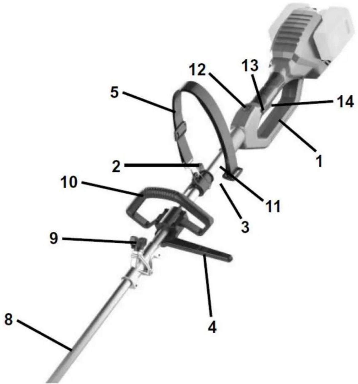
Figure 1: Brush cutter – upper part
- Rear handle 9. Shaft locking knob
- Socket wrench 10. Auxiliary handle
- Shoulder stra p buckle 11. Upper shaft
- Lower part of auxiliary handle 12. Variable speed dial
- Shoulder strap 13. Lock-off button
- Lower shaft 14. On/Off Switch
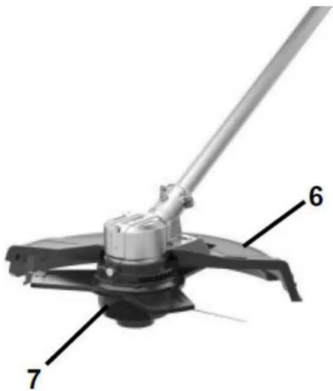
Figure 2: Brush cutter – lower part
- Safety guard
- Trimmer head
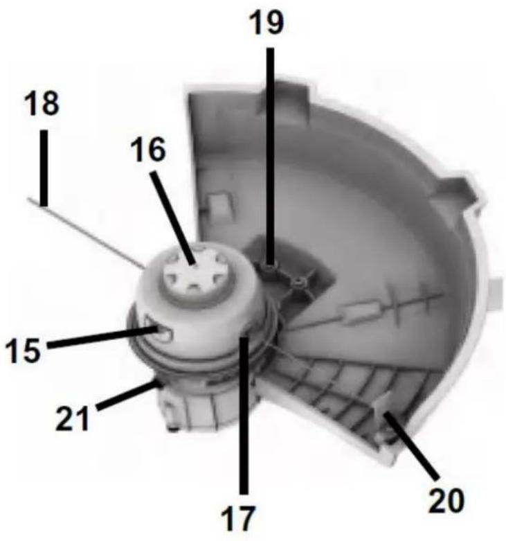
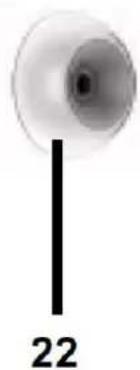
Figure 3: Brush cutter head incl. Thread head (view from below)
- Spool housing cap release latch
- Bump button for line feeding
- Eyelet
- Cutting line
- Safety guard fixing screw
- Line cutter
- Spindle lock button
natural_image
Simple circular diagram with a vertical line and the number 22 below (no text or symbols within the diagram itself)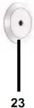
natural_image
Simple diagram of a vertical line with a circular top and number 23 below (no text or symbols on the diagram itself)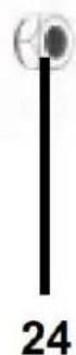
Figure 4: Fastening accessories
- Blade fixing plate
- Bla de fixing cover
- Blade fixing nut
29. Assembly
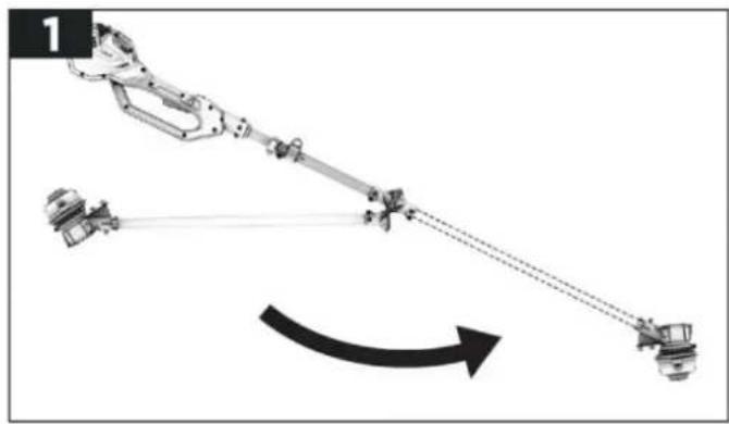
Connection of upper shaft with lower shaft
- Unfold the lower shaft as shown below.
ATTENTION!
When unfolding, be careful not to damage the cable inside the shaft.
- Align the two shafts with each other so that you can connect both shafts together using the wing screw. Tighten the thumbscrew firmly for a secure connection.
natural_image
Diagram of a robotic arm connecting two identical vehicles with a curved arrow indicating motion (no text or symbols)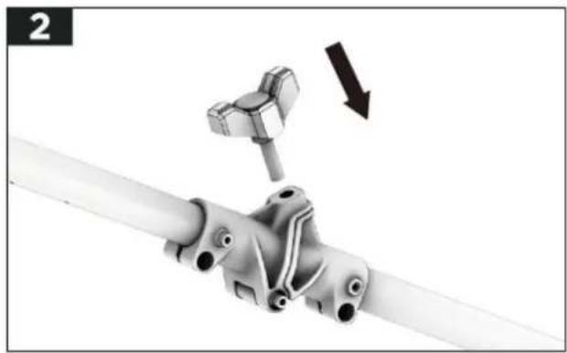
natural_image
Mechanical assembly diagram showing a pipe connection with a clamp and directional arrow (no text or symbols)Assembly of the auxiliary handle
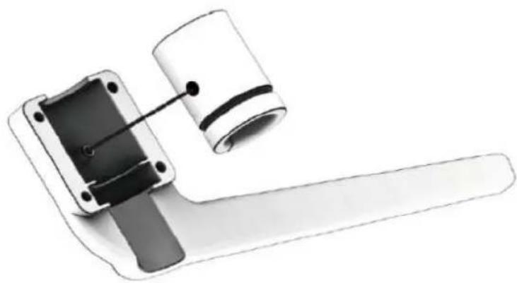
The auxiliary handle to be attached to the brush cutter consists of the upper and lower parts.
- Attach the rubber sleeve to the lower part of auxiliary handle by aligning the hole on the rubber sleeve with the cylinder located inside of the lower part of auxiliary handle as shown
3
natural_image
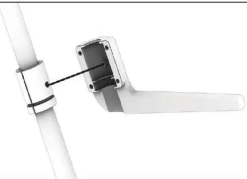
Diagram of a mechanical device with a cylindrical component inserted into a housing (no text or symbols visible)- After combine the rubber sleeve with the lower part of auxiliary handle, attach this combination to the upper shaft by aligning the cylinder located inside of the lower part of auxiliary handle with the hole on the upper shaft as shown
4
natural_image
Pure mechanical assembly diagram showing pipe connection and bracket (no text or symbols)NOTE:
Makesure the arm of the lower part of auxiliary handle is pointing to the left of the operator.
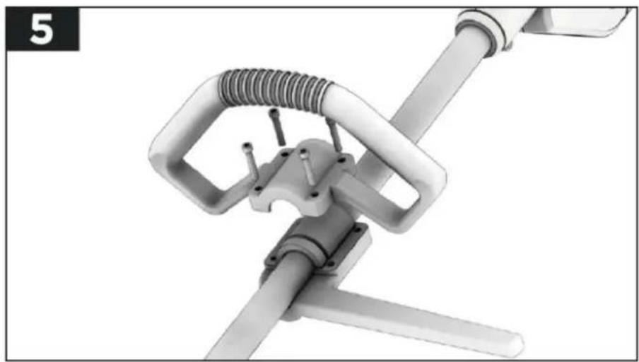
- Lay down the upper part of auxiliary handle onto the upper shaft and the lower part of auxiliary handle as shown in Fig.5. Make sure the 4 holes on the upper part of auxiliary handle are aligned with the 4 holes on the lower part of auxiliary handle. Insert the provided 4 auxiliary handle locking bolts through the aligned holes and tighten the the bolts fully by an Allen Key
natural_image
Mechanical device with attached spring and lever mechanism (no visible text or symbols)Assembly of the safety guard
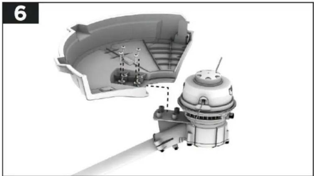
- Turn the tool over and p lace the tool on a f lat surface. Align and attach the safety guard to the trimmer head as shown in Fig.6. Align the 4 fixing holes on the safety guard with the 4 fixing holes located next to the trimmer head.
- Insert the provided 4 safety guard fixing screws into the aligned holes. Tighten the screws fully using the Phillips end of the provided socket wrench. Check to see if the safety guard is installed well
natural_image
3D mechanical assembly diagram showing internal components and a motor housing (no text or symbols)30. Attaching the shoulder strap
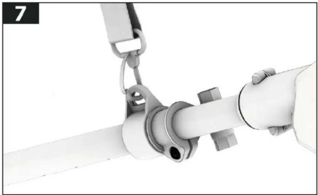
A shoulder strap is provided with this tool to help your routine work. Hook this shoulder strap onto the shoulder strap bracket as shown
natural_image
Close-up of a hand holding a white cylindrical pipe with attached clamps and fittings (no text or symbols visible)Assembly of the 3-teeth blade
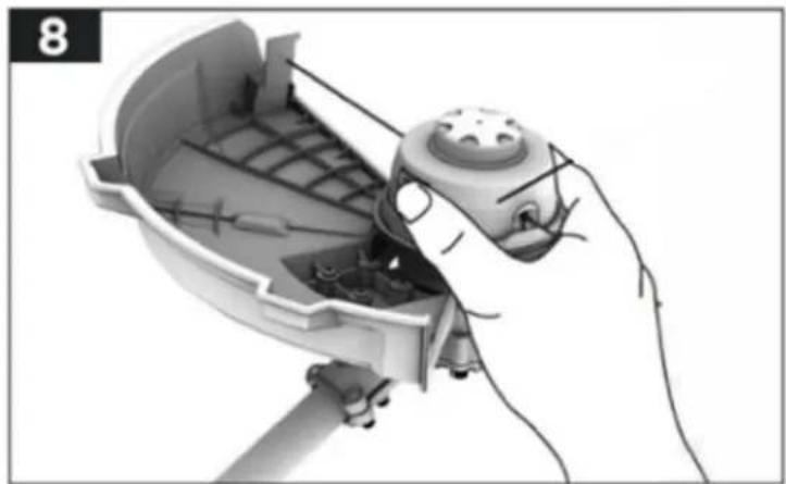
The trimmer head is composed of spool housing, spool and spool housing cap. To remove the trimmer head, you should remove the spool housing cap, spool and the spool housing successively
- Turn the tool over and place the tool on a flat surface. Press and hold the 2-spool housing cap release latches, and take out the spool housing cap (27) first.
natural_image
Illustration of a robotic hand holding a small mechanical device with internal components (no text or symbols visible)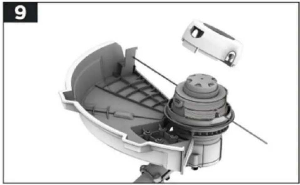
natural_image
Cutaway view of a mechanical device showing internal components and housing (no text or symbols visible)- Then remove the spool

natural_image
3D cutaway view of a mechanical component with internal structure and housing (no text or symbols visible)- To remove the spool housing, firstly press the spindle lock button to stop the spindle rotating, and then loosen the spool housing by rotating it counter-clockwise. Remove the spool housing
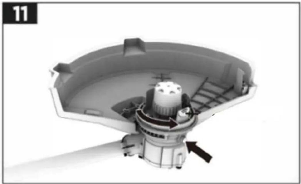
natural_image
3D rendering of a mechanical device with internal components and an arrow indicating direction (no text or symbols)Take out the 3-teeth blade from the paper bag, and then remove the blade protective cover. Place the 3-teeth blade onto the spindle, then place the blade fixing plate, blade fixing cover and blade fixing nut through the spindle in turn.
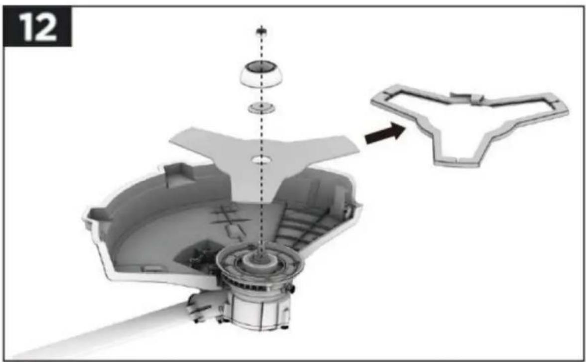
natural_image
Exploded view diagram of a mechanical assembly with no visible text or symbolsAssembly the thread head / trimmer head
To install the trimmer head, following the above steps in reverse order. Firstly, place the spool housing onto the spindle. Press the spindle lock button to stop the spindle rotating, and tighten the spool housing by rotating it clockwise. Then put the spool in the spool housing. Finally cover the spool housing cap. Notice that the spool housing cap release latch on the spool housing should be aligned with the spool housing cap fixing hole on the spool housing cap while covering the cap. A "click" will be heard when the cap is locked in place
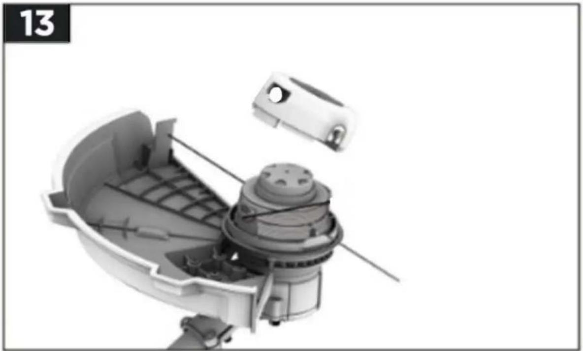
natural_image
Cutaway view of a mechanical device showing internal components and housing (no text or symbols)31. Working with the brush cutter
Before the start
- Ensure the switch is in the off position and disconnect the battery from the tool.
- Examine the general condition of the tool. Inspect the guard, switch, cord, check for loose screws, improper mounting, broken parts and any other condition that may affect its safe operation. If abnormal noise or vibration occurs during operation, turn the tool off immediately and have the problem corrected by a qualified repair person.
- Ensure that you are on a flat surface and have secure footing.
- Check that the line touches or goes beyond the edge of the guard.
- Check the cutting attachment, never use blades that are dull, cracked or damaged.
- Wear the shoulder belt so that it lies on the one side of shoulder as shown in below pic. It can be removed quickly from your body in case of danger
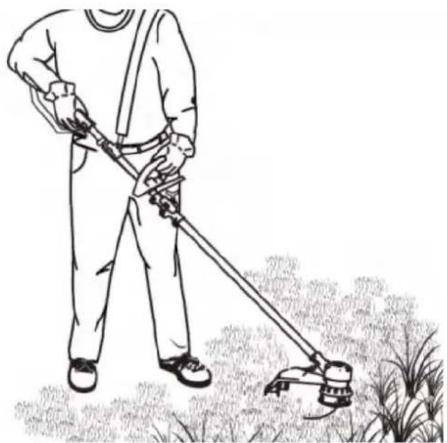
natural_image
Line drawing of a person using a long-handled lawn power tool in a grassy field (no text or symbols)Starting the brush cutter
Depress and hold the lock-off button, and then squeeze the on/off switch and hold it. Once the tool is switched on, you can release the lock-off button.
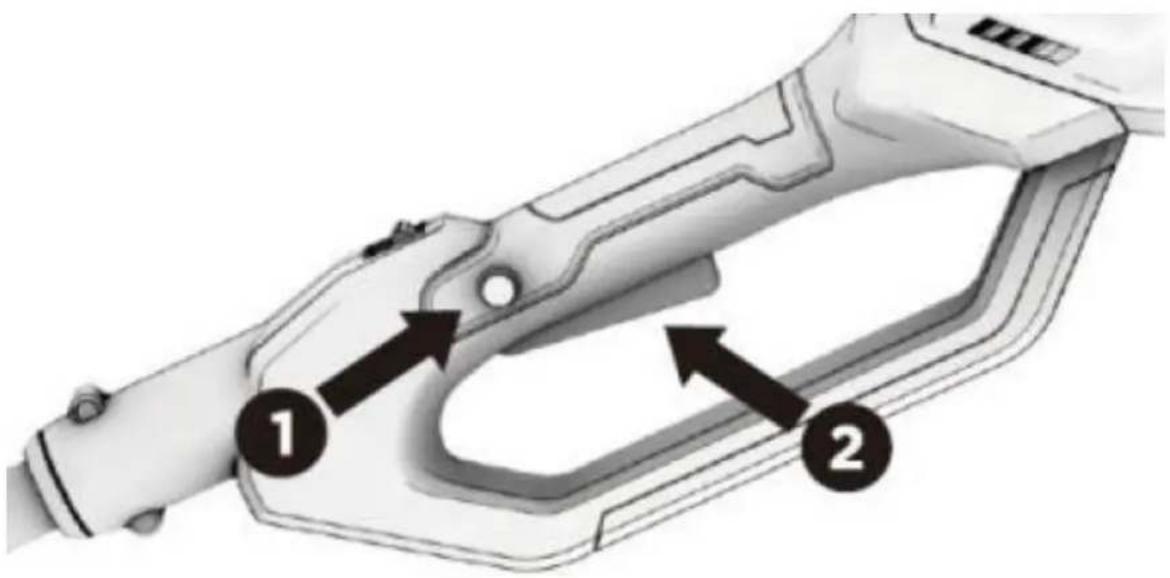
Stopping the brush cutter
• Simply release the trigger.
• The machine stops completely after a few seconds.
• Discount the battery from the tool for safety.
Variable speed control
To set the variable speed, first switch on the brush cutter. Next, turn the variable speed control forward or backward to adjust the speed as needed (see the following figure). You can choose between two speeds (I or II). For light work, we recommend the slower speed setting, this will increase the running time of the brush cutter.
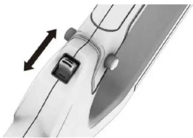
natural_image
Close-up of a mechanical component with directional arrows indicating movement or force (no text or symbols)32. Trimming / cutting grass
WICHTIG!
Be careful not to overload the brush cutter. If you overload the brush cutter, the motor may be damaged. To avoid overloading, cut long or difficult grass in stages with several simple cuts. Make sure that the rotating parts do not cut into the ground, as this will cause the cutting devices to wear out more quickly and could damage the spindle and motor of the brush cutter.
- Assemble the thread head.
- Check if there is enough of the trimming line on the spool
• Install the battery pack. - Hold the brush cutter with both hands, one hand on the rear handle and the other hand on the auxiliary handle. Stand on a solid and secure surface.
- Start the brush cutter.
• Firmly grip both handles, move slowly and steadily using a side to side sweeping motion. - Do not use force on the brush cutter. Cut with the tip of the thread.
- Stop the grass trimmer when finished. Remove the battery pack.
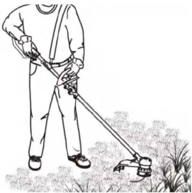
natural_image
Line drawing of a person using a long-handled lawn brush to cut grass (no text or symbols)Manual_FX-E2MS_Int24_rev2
33. Use the automatic feeding
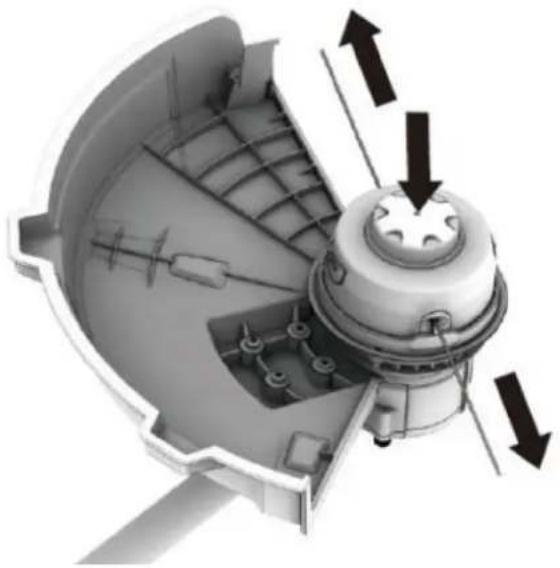
When using as a grass trimmer, this tool is equipped with a bump button for line feeding which allows the operator to feed the line without stopping the motor.
- Switch on the brush cutter
• Lightly tap the button on the surface.
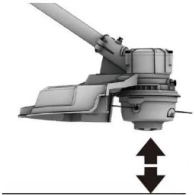
natural_image
Mechanical device with two upward and downward arrows indicating motion or force (no text or symbols)• The line will be fed out each time the bump button is tapped
NOTICE: When the line is fed out too much, it will be cut by the line cutter to a proper length.
- If the thread is not cut correctly, the bobbin may become tangled. In this case, take out the spool and rewind the line (see winding up new line).
- If there is too little thread on the spool, you may not be able to feed the thread through the automatic tapping mechanism. In this case, switch off the device and proceed as in the following chapter.
34. Manual feeding of the thread
Turn off the brush cutter and remove the battery pack. To manually feed the line, press bump button for line feeding while gently pulling out the line, until the line is long enough to reach the line cutter
natural_image
Technical illustration of a mechanical device with directional arrows indicating motion or force (no text or symbols present)35. Use the 3-teeth blade
• Before use, check whether the 3-tooth blade is installed correctly.
• Install the battery.
- Hold the brush cutter with both hands, one hand on the rear handle and the other hand on the front round handle. Stand on a firm and safe surface.
- Start the brush cutter.
- Hold both handles firmly and move slowly and evenly. To cut overgrowth and brush, lower the rotating 3-tooth blade onto the vegetation to separate the vegetation.
- Move the brush cutter close to the ground as when trimming grass (swing left and right) to cut young trees or grass.
• Dip the blade from above when cutting through thick brush or undergrowth.
NOTE: Do not use force on the brush cutter.
- Stop the brush cutter when finished. Remove the battery.
36. Working Instructions
PLEASE NOTE:
The higher the cutting unit is above the ground, the greater the risk of injury from cuttings thrown to the side. Always try to keep the protective shield just above the ground!
Do not attempt to cut wood material with a larger diameter. The 3-teeth blade can get stuck or the entire brush cutter can be jerked forward. This could result in damage to the blade or brush cutter or loss of control of the brush cutter, which could result in injury.
Improper use of a blade can cause it to crack, chip, or break. There is also a significant risk of injury here.
Parts thrown out can seriously injure the operator or bystanders. To reduce the risk of injury, it is important to take the following precautions:
- Avoid contact with hard or solid foreign objects such as concrete, stones or pieces of metal.
- Never cut wood or bushes with a trunk diameter of more than 2 cm.
- Check the knife at short regular intervals for signs of damage.
- Do not continue working with a damaged knife.
- Sharpen the knife regularly (if it has become noticeably dull).
- Do not hold the cutting unit higher than your knees. This can quickly lead to a loss of control.
37. Wind a new thread
Please note:
Use only a thread with a diameter of 0.08 inch / 2 mm. Using other diameters can cause damage to the brush cutter.
• Take out the spool as already described.
- Remove any remaining old thread from the spool.
• Take a new thread approximately 2.5 m long.
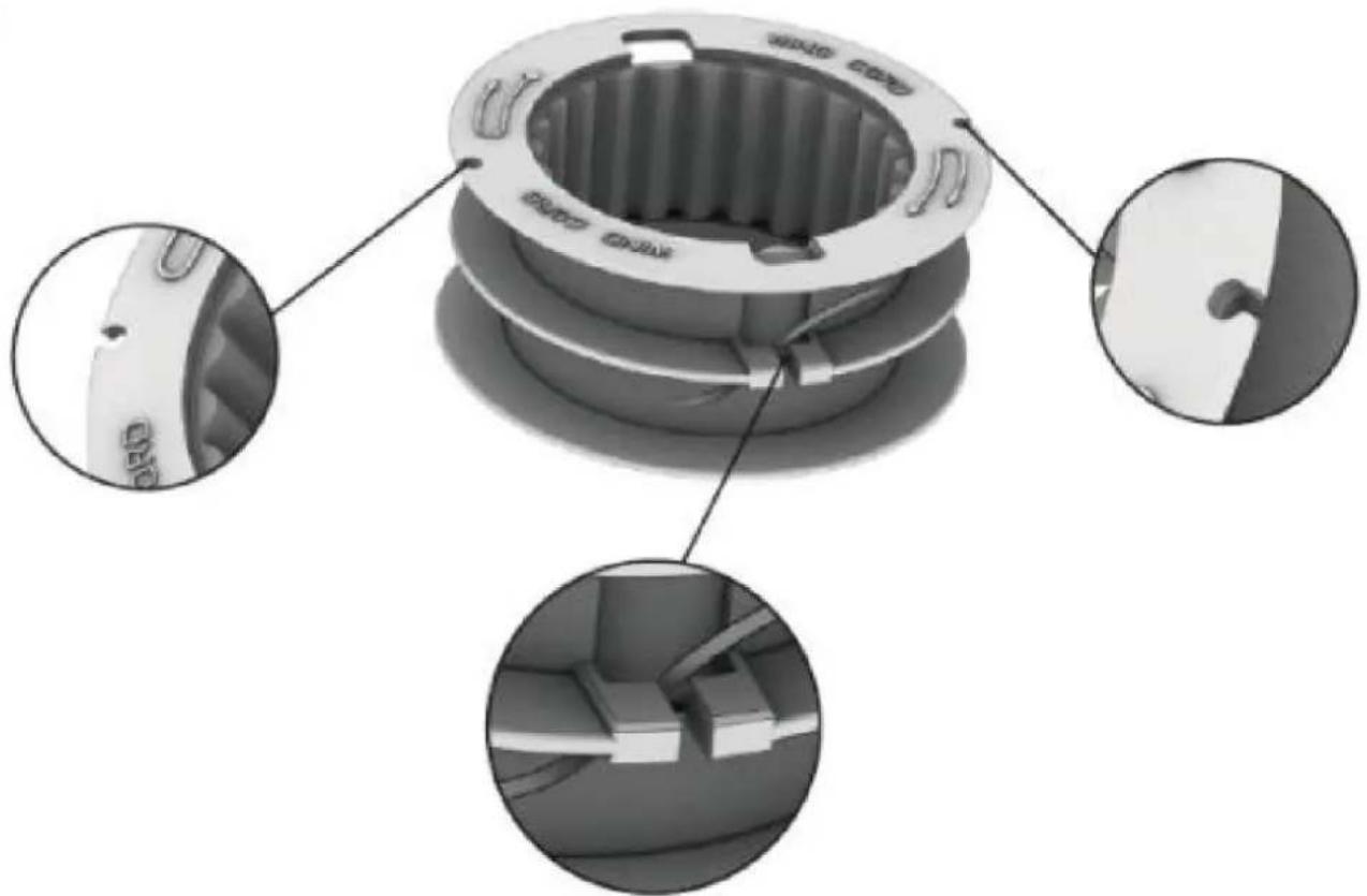
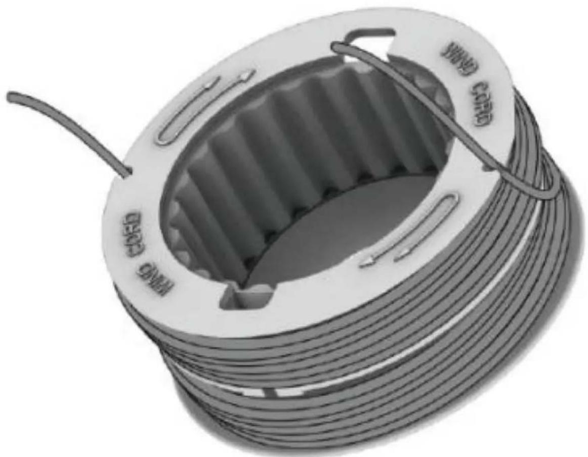
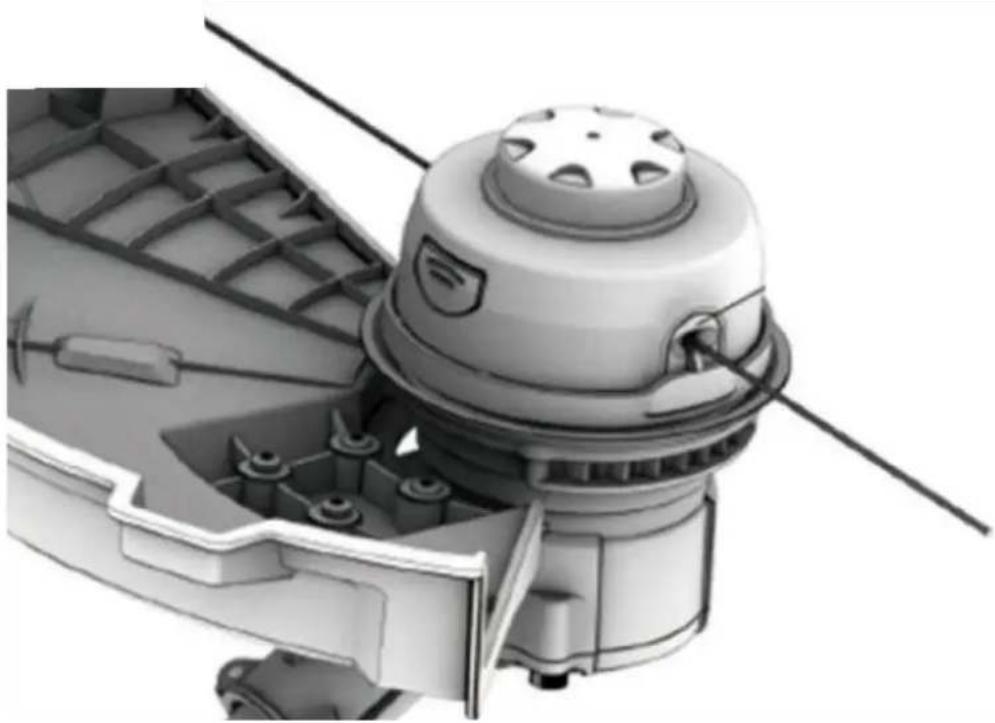
Insert a small portion of the thread into one of the holes in the top of the spool and wind about half of the thread in the direction of the arrows shown at the top of the spool.
Then guide the remaining second half through the recess in the lower part of the spool and wind up the thread so that at the end you have enough thread to thread it into the other upper hole (see the following illustrations).
natural_image
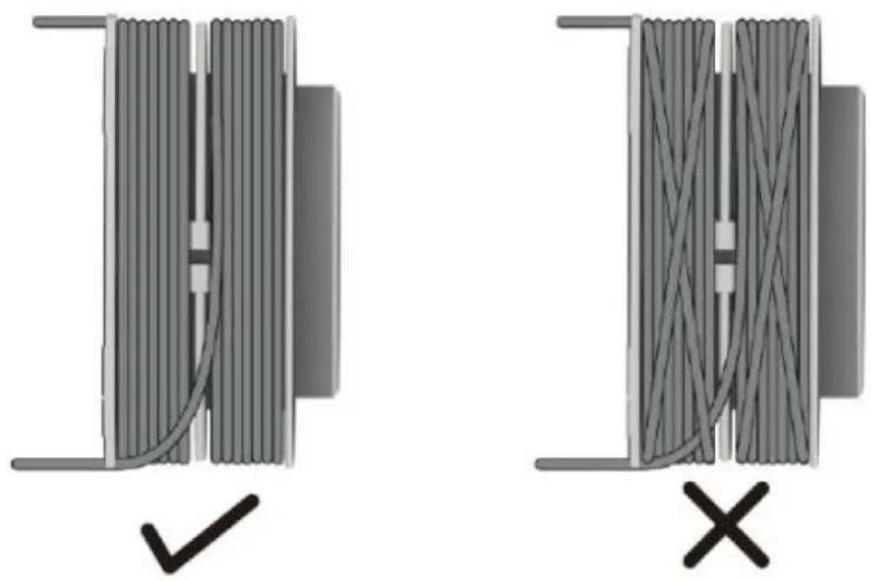
Illustration of a coiled cable with a wire loop, no text or symbols present- Make sure that the thread is wound neatly. Otherwise, the thread may get caught when using the automatic typing function (see following figure)
natural_image
Two mechanical cable assemblies with coiled wires and connectors, one marked with a checkmark (no text or symbols)- Do not overfill the coil! After winding the thread, there should be at least 6 mm (1/4 inch) of space between the thread and the outer edge of the spool.
-
- Then reinsert the coil. Thread the ends of the new thread through the eyelets and pull the thread out until it touches the blade on the protective shield.
natural_image
Mechanical component diagram showing a motor or gearbox assembly with no visible text or symbols38. Maintenance and care
Attention: before any work on the power tool, remove the battery from the device
Do not use water or liquid detergents.
- Remove dirt and dust from the housing with a brush or dry cloth.
- Remove grass clippings from the bottom of the grass trimmer.
- Keep the contacts of the battery and device clean and dust-free.
- To change the blades, push the blade towards the cutting insert. If the blade is anchored in the larger opening, you can remove the blade and insert a new blade in reverse order. Please make sure that the blade is firmly fixed in the anchorage before using the device again.
39. Disposal

WARNING!
Make used power tools unusable before disposal:
- mains-operated power tools by removing the connecting plug,
• cordless power tools by removing the battery.

For EU countries only
Do not throw power tools in household waste! According to the European Directive 2012/19/EC on waste electrical and electronic equipment and its implementation in national law, used electrical equipment must be collected separately and sent for environmentally sound recycling. Recovery of raw materials instead of waste disposal. The device, accessories, and packaging should be recycled in an environmentally friendly manner. Plastic parts are marked for recycling according to type.

WARNING!
Do not throw batteries in the household waste, fire, or water. Do not open worn-out batteries.
Batteries should be collected, recycled, or disposed of in an environmentally friendly manner.
For EU countries only: According to Directive 2006/66/EC, defective or exhausted batteries must be recycled.
i NOTE:
Please contact your local authority/city for information on disposal options,
Recycling raw materials instead of waste disposal.
- Technical Data
| 40V battery brush cutter | FX-E2MS |
| Rotations per minute | Zwischen 4500 U/min und 6000 U/min |
| Thread head working range Working range 3-tooth blade | 350mm255mm |
| Thickness of the 3-tooth blade | 1,4mm |
| Measured sound power level | 81 (LpA) db |
| Guaranteed sound power level | 91,2 (LwA) db |
| Thread diameter | 2mm |
| Weight (without battery) | 4,55 kg |
41. EU Declaration of Conformity
Hersteller / Producer FUXTEC GmbH
Hereby we declare that the above mentioned machine meet the essential safety and health
requirements of the above stated EC directives. Any manipulation or change of the machine not being
explicitly authorized by us in advance renders this document null and void.
Storage of technical documents: FUXTEC GmbH • Kappstraße 69 • 71083 Herrenberg • Germany, L.
Zirkler, CEO
Herrenberg, 12 ^th of January 2024
C. Jille
natural_image
Diagram of a robotic arm with connected sensors and a directional arrow indicating motion (no text or symbols)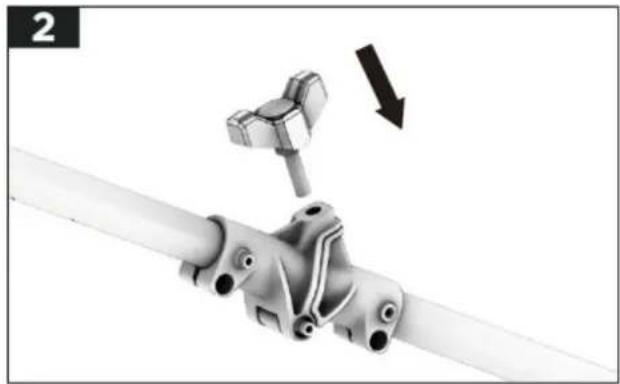
natural_image
Mechanical assembly diagram showing a bracket with a hammer and arrow indicating motion (no text or symbols)natural_image
Diagram of a mechanical device with a cylindrical component inserted into a housing (no text or symbols)natural_image
Close-up of a white mechanical component with a black bracket and a separate L-shaped bracket, no visible text or symbols.HINWEIS:
natural_image
Mechanical assembly diagram showing a clamp and spring mechanism (no text or symbols)natural_image
3D mechanical assembly diagram showing internal components and a motor housing (no text or symbols)Installation de la sangle montante
natural_image
Close-up of a hand holding a white cylindrical pipe with attached clamps and fittings (no text or symbols visible)natural_image
Illustration of a hand using a handheld device to adjust internal components (no text or symbols visible)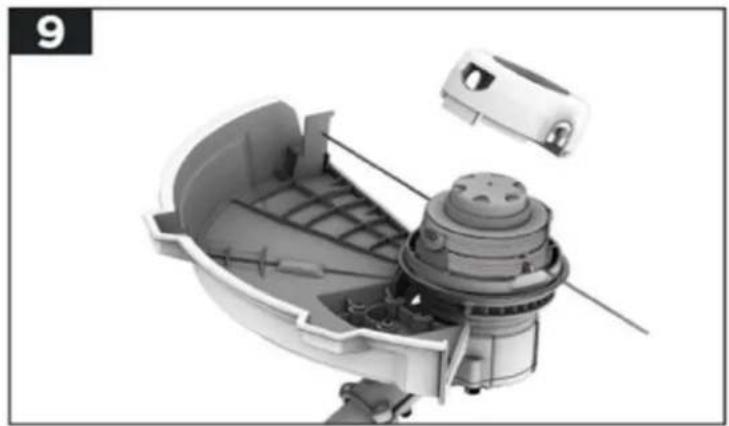
natural_image
Cutaway view of a mechanical device showing internal components and housing (no text or symbols visible)natural_image
3D cutaway view of a mechanical component with internal parts and a cylindrical housing (no text or symbols visible)natural_image
3D cutaway view of a mechanical device with internal components and an arrow indicating direction (no text or symbols)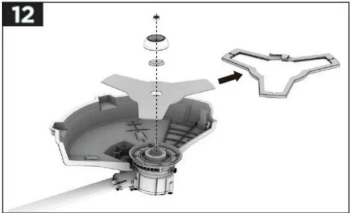
natural_image
3D mechanical assembly diagram showing internal components and a close-up of a component with an arrow indicating direction (no text or symbols present)natural_image
Cutaway view of a mechanical device showing internal components and a housing (no text or symbols visible)natural_image
Line drawing of a person using a manual lawn power tool in a grassy field (no text or symbols)natural_image
Close-up of a mechanical component with directional arrows indicating movement or force (no text or symbols)natural_image
Line drawing of a person using a long-handled manual lawn power tool in a grassy field (no text or symbols)natural_image
Mechanical device with two directional arrows indicating movement or force (no text or symbols)natural_image
Technical illustration of a mechanical device with internal components and directional arrows indicating motion (no text or symbols)56. Avantages de la lame 3 dents
natural_image
Technical illustration of a mechanical component with a dome-shaped top and internal structure (no visible text or symbols)applicables / applicables normes
EN 60335-1:2012+A11+A13+A1+A14+A2+A15
EN 62233:2008
EN 50636-2-100:2014
EN ISO 11806-1:2022
EN CEI 55014-1:2021 EN CEI 55014-2:2021
natural_image
Diagram of a robotic arm connecting two vehicles with a dotted line indicating motion (no text or symbols)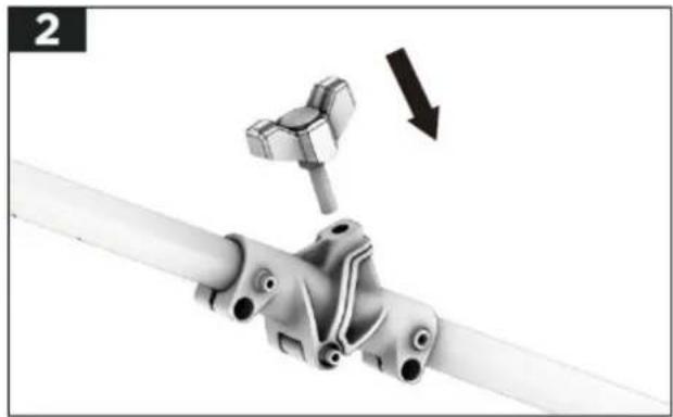
natural_image
Mechanical assembly diagram showing a bracket with a hammer and nut, no text or symbols presentnatural_image
Illustration of a mechanical device with a cylindrical component and a flat base, no text or symbols presentnatural_image
Mechanical assembly diagram showing a pipe joint with a bracket and handle (no text or symbols)HINWEIS:
natural_image
Mechanical device with coiled spring and lever mechanism (no text or symbols visible)natural_image
3D cutaway diagram of a mechanical assembly showing internal components and a base housing (no text or symbols)natural_image
Close-up of a hand holding a white cylindrical pipe with attached clamps and fittings (no text or symbols visible)natural_image
Illustration of a hand holding a handheld device with internal components (no text or symbols visible)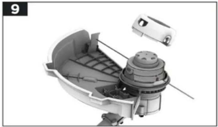
natural_image
Cutaway view of a mechanical device showing internal components and housing (no text or symbols visible)natural_image
Cutaway view of a mechanical component showing internal structure and housing (no text or symbols)natural_image
Cross-sectional diagram of a spacecraft or spacecraft with a central body and directional arrows, no visible text or symbols.natural_image
3D mechanical assembly diagram showing internal components and a close-up of a component with an arrow indicating direction (no text or symbols present)natural_image
Cutaway view of a mechanical device showing internal components and housing (no text or symbols visible)natural_image
Line drawing of a person using a manual lawn power tool in a grassy field (no text or symbols)natural_image
Close-up of a mechanical component with directional arrows indicating movement or force (no text or symbols)natural_image
Line drawing of a person using a long-handled manual lawn brush to cut grass (no text or symbols)natural_image
Mechanical device with two directional arrows indicating movement or force (no text or symbols)natural_image
Cross-sectional diagram of a mechanical device showing internal components and directional arrows (no text or symbols)natural_image
Technical illustration of a mechanical component with a dome-shaped top and internal structure (no visible text or symbols)natural_image
Diagram of a robotic arm with connected components and motion arrows, no text or symbols present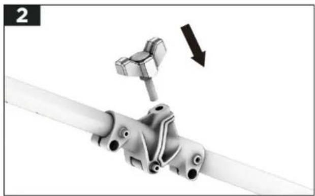
natural_image
Mechanical assembly diagram showing a hammer inserted into a pipe with a downward arrow indicating motion (no text or symbols present)natural_image
Diagram of a mechanical device with a cylindrical component inserted into a housing (no text or symbols visible)natural_image
Mechanical assembly diagram showing a pipe joint with a bracket and handle (no text or symbols)HINWEIS:
natural_image
Mechanical device with coiled spring and lever mechanism (no text or symbols visible)natural_image
3D cutaway diagram of a mechanical assembly showing internal components and a base housing (no text or symbols)natural_image
Close-up of a hand holding a white pipe with attached clamps and fittings (no text or symbols visible)natural_image
Illustration of a hand holding a handheld device with internal components (no text or symbols visible)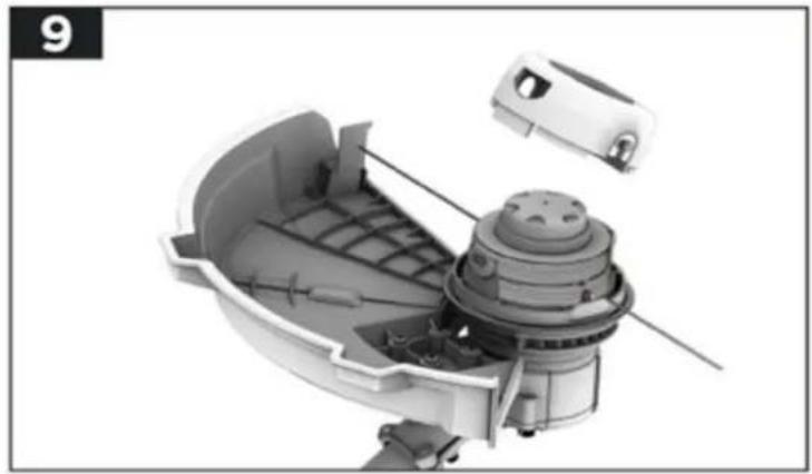
natural_image
Cutaway view of a mechanical device showing internal components and housing (no text or symbols visible)natural_image
Cutaway view of a mechanical component showing internal structure and housing (no text or symbols)natural_image
3D cutaway view of a mechanical device with internal components and an arrow indicating direction (no text or symbols)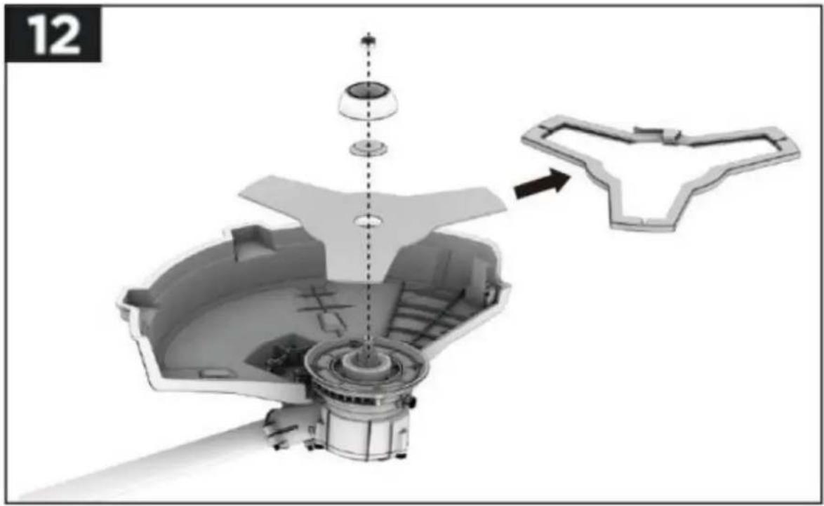
natural_image
Exploded view diagram of a mechanical assembly with no visible text or symbolsnatural_image
Cutaway view of a mechanical device showing internal components and housing (no text or symbols)natural_image
Line drawing of a person using a manual lawn power tool in a grassy field (no text or symbols)93. Detener la desbrozadora
natural_image
Close-up of a mechanical component with directional arrows indicating movement or force (no text or symbols visible)natural_image
Line drawing of a person using a long-handled lawn power tool in a grassy field (no text or symbols)natural_image
Mechanical device with two directional arrows indicating movement or force (no text or symbols)- El hilo a
natural_image
3D technical illustration of a mechanical component with directional arrows indicating flow or movement (no text or symbols)natural_image
Close-up of a mechanical component with a circular flange and labeled parts (no readable text or symbols)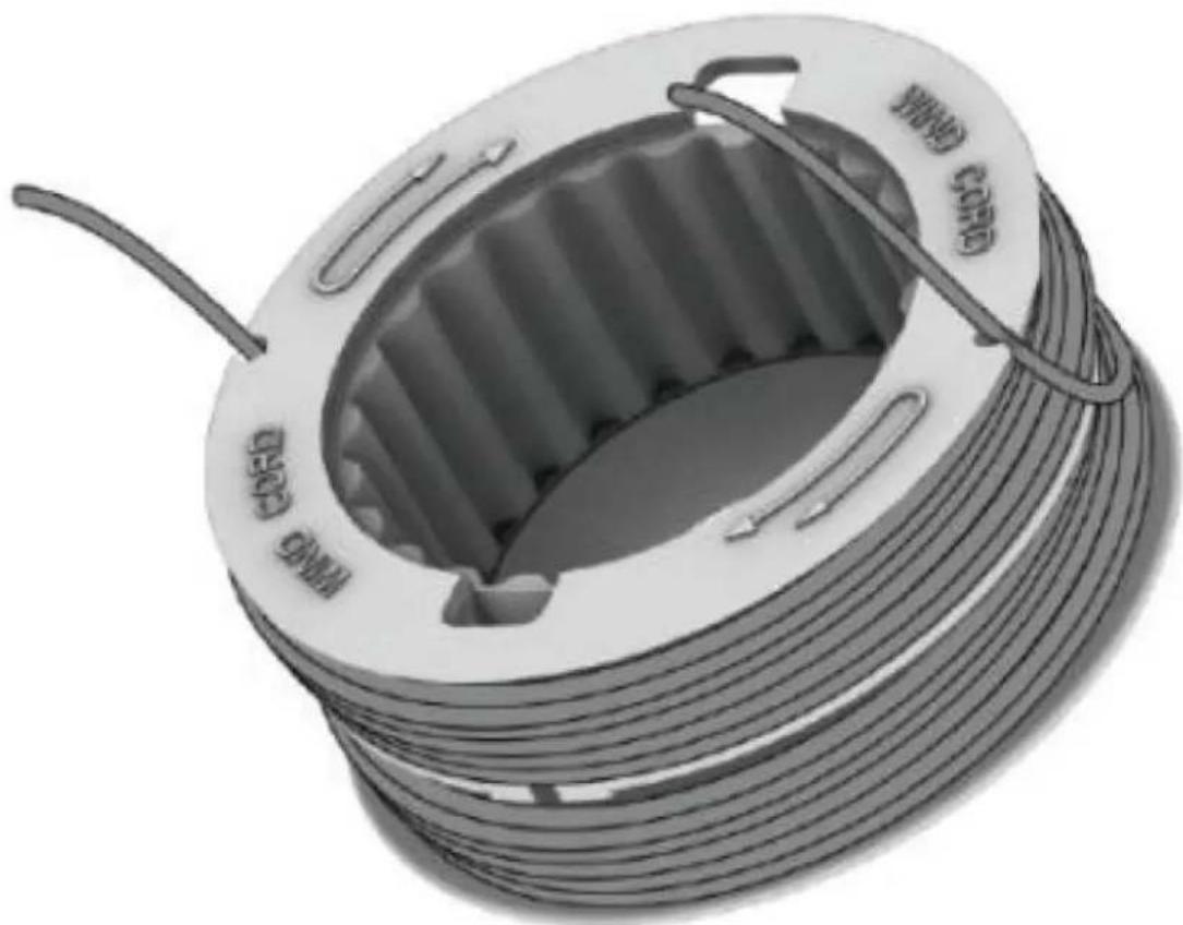
natural_image
Illustration of a coiled cable with labeled 'COLD' and 'FORD CORD' on its spool (no additional text or symbols)natural_image
Close-up of a mechanical component with a dome-shaped top and internal structure (no visible text or symbols)natural_image
Diagram of a robotic arm with connected components and motion arrows, no text or symbols present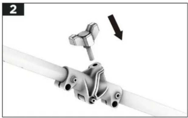
natural_image
Mechanical assembly diagram showing a pipe connection with a hammer and nut, no text or symbols presentnatural_image
Diagram of a mechanical device with a handle and internal components, no visible text or symbolsnatural_image
Mechanical assembly diagram showing a pipe joint with a bracket and a handle (no text or symbols)natural_image
Mechanical assembly diagram showing a clamp mechanism with no visible text or symbolsnatural_image
3D mechanical assembly diagram showing internal components and a motor housing (no text or symbols)Instalando a cinta riser
natural_image
Close-up of a hand holding a white cylindrical pipe with attached clamps and fittings (no text or symbols visible)natural_image
Illustration of a robotic hand holding a small mechanical device with internal components (no text or symbols visible)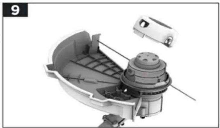
natural_image
Cutaway view of a mechanical device showing internal components and housing (no text or symbols visible)natural_image
3D cutaway view of a mechanical component with internal structure and housing (no visible text or symbols)natural_image
3D rendering of a mechanical component with internal structure and directional arrows (no text or symbols)natural_image
Exploded view diagram of a mechanical assembly with no visible text or symbolsnatural_image
Cutaway view of a mechanical device showing internal components and housing (no text or symbols)natural_image
Line drawing of a person using a manual lawn power tool in a grassy field (no text or symbols)natural_image
Close-up of a mechanical component with directional arrows indicating movement or force (no text or symbols visible)natural_image
Line drawing of a person using a long-handled manual lawn power tool in a grassy field (no text or symbols)natural_image
Mechanical device with two directional arrows indicating movement or force (no text or symbols)natural_image
Cross-sectional diagram of a mechanical device showing internal components and directional arrows (no text or symbols)natural_image
Close-up of a mechanical component with a dome-shaped top and internal structure (no visible text or symbols)natural_image
Diagram of a robotic arm connecting two identical vehicles with a curved arrow indicating motion (no text or symbols)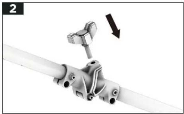
natural_image
Mechanical assembly diagram showing a pipe connection with a clamp and directional arrow (no text or symbols)Montage rond handvat
natural_image
Diagram of a mechanical device with a handle and internal components, no visible text or symbolsnatural_image
Mechanical assembly diagram showing a pipe joint with a bracket and handle (no text or symbols)HINWEIS:
natural_image
Mechanical device with attached spring and lever mechanism (no visible text or symbols)natural_image
3D technical illustration of a mechanical assembly with internal components and a base component (no text or symbols)natural_image
Close-up of a hand holding a white cylindrical pipe with attached clamps and fittings (no text or symbols visible)natural_image
Hand holding a small mechanical device with internal components, no visible text or symbols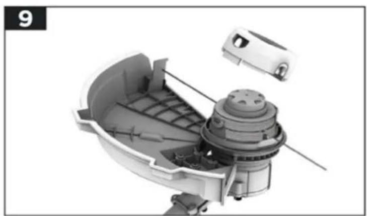
natural_image
Cutaway view of a mechanical device showing internal components and housing (no text or symbols visible)natural_image
3D cutaway view of a mechanical component with internal structure and housing (no text or symbols visible)natural_image
3D cutaway view of a mechanical device with internal components and an arrow indicating direction (no text or symbols)natural_image
Exploded view diagram of a mechanical assembly with no visible text or symbolsnatural_image
Cutaway view of a mechanical device showing internal components and housing (no text or symbols)natural_image
Line drawing of a person using a manual lawn power tool in a grassy field (no text or symbols)natural_image
Close-up of a mechanical component with directional arrows indicating movement or force (no text or symbols visible)137. Gras trimmen/maaien
BELANGRIJK!
natural_image
Technical illustration of a mechanical device with directional arrows indicating motion or force (no text or symbols present)natural_image
Close-up of a mechanical component with a dome-shaped top and internal structure (no visible text or symbols)natural_image
Diagram showing a robotic arm connecting two vehicles with a curved arrow indicating motion (no text or symbols)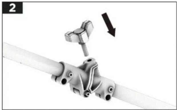
natural_image
Mechanical assembly diagram showing a bracket with a hammer and arrow indicating motion (no text or symbols)Montering runt handtag
natural_image
Diagram of a mechanical device with a handle and internal components, no visible text or symbolsnatural_image
Close-up of a white mechanical component with a black bracket and a separate L-shaped bracket, no visible text or symbols.HINWEIS:
natural_image
Mechanical assembly diagram showing a clamp and spring mechanism (no text or symbols)natural_image
3D mechanical assembly diagram showing internal components and a motor housing (no text or symbols)Montering av stigremmen
natural_image
Close-up of a hand holding a white pipe with attached clamps and fittings (no text or symbols visible)natural_image
Illustration of a hand holding a small device with internal components, no visible text or symbols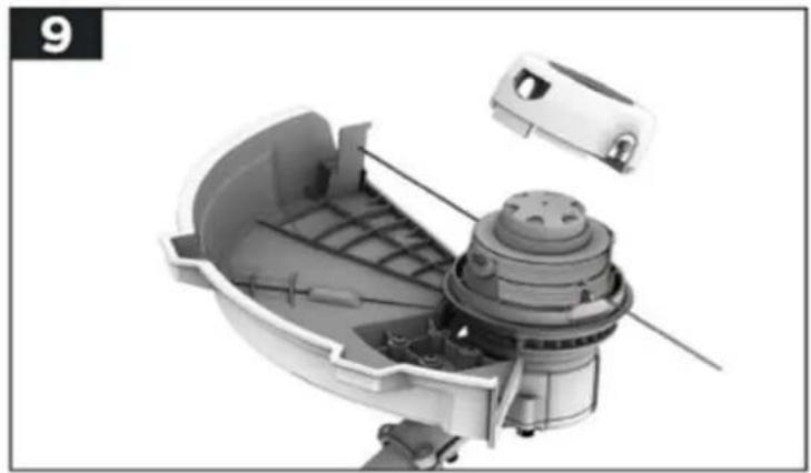
natural_image
Cutaway view of a mechanical device showing internal components and housing (no text or symbols visible)natural_image
3D cutaway view of a mechanical component with internal structure and housing (no visible text or symbols)natural_image
3D rendering of a mechanical device with internal components and an arrow indicating direction (no text or symbols)natural_image
3D cutaway diagram of a mechanical assembly with no visible text or symbolsnatural_image
Cutaway view of a mechanical device showing internal components and housing (no text or symbols)natural_image
Line drawing of a person using a long-handled manual lawn power tool in a grassy field (no text or symbols)Starta röjsågen
natural_image
Close-up of a mechanical component with directional arrows indicating movement or force (no text or symbols)natural_image
Line drawing of a person using a long-handled lawn power tool in a grassy field (no text or symbols)natural_image
Mechanical device with two upward and downward arrows indicating motion or force (no text or symbols)natural_image
Cross-sectional diagram of a mechanical device with internal components and directional arrows indicating motion (no text or symbols)natural_image
Close-up of a mechanical component with a dome-shaped top and internal structure (no visible text or symbols)E-post: info@fuxtec.de Web: www.fuxtec.de
Bezeichnung / namn
40V Akku Motorsense / E 2 40 V Ryckare
POLSKA WERSJA JEZYKOWA
natural_image
Diagram of a robotic arm with connected sensors and a directional arrow indicating motion (no text or symbols)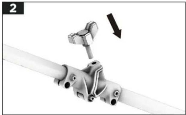
natural_image
Mechanical assembly diagram showing a bracket with a hammer and arrow indicating motion (no text or symbols)natural_image
Diagram of a mechanical device with a cylindrical component inserted into a housing (no text or symbols)natural_image
Mechanical assembly diagram showing a pipe joint with a bracket and mounting bracket (no text or symbols)HINWEIS:
natural_image
Mechanical assembly diagram showing a clamp and spring mechanism (no text or symbols)natural_image
3D cutaway diagram of a mechanical assembly showing internal components and a base housing (no text or symbols)natural_image
Close-up of a hand holding a white cylindrical pipe with attached clamps and fittings (no text or symbols visible)natural_image
Illustration of a hand holding a small device with internal components, no visible text or symbols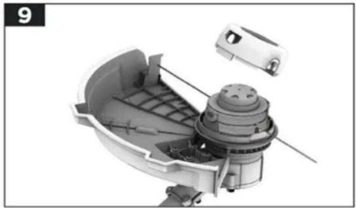
natural_image
Cutaway view of a mechanical device showing internal components and housing (no text or symbols visible)natural_image
3D cutaway view of a mechanical component with internal structure and housing (no text or symbols visible)natural_image
Exploded view diagram of a mechanical assembly with no visible text or symbolsnatural_image
Cutaway view of a mechanical device showing internal components and housing (no text or symbols)natural_image
Line drawing of a person using a manual lawn power tool in a grassy field (no text or symbols)natural_image
Close-up of a mechanical component with directional arrows indicating movement or force (no text or symbols)natural_image
Line drawing of a person using a manual lawn power tool in a grassy field (no text or symbols)natural_image
Mechanical device with two upward and downward arrows indicating force or movement (no text or symbols)natural_image
Cross-sectional diagram of a mechanical device with internal components and directional arrows indicating motion (no text or symbols)natural_image
Close-up of a mechanical component with a dome-shaped top and internal structure (no visible text or symbols)




- Inhalt
- VERSION FRANCAISE 64
- Montage Rundgriff
- Installation des Schutzschildes
- Introduction and safety
- WARNING!
- Workplace Safety
- Electrical Safety
- Safety of Persons
- Use and treatment of the power tool
- Use and handling of the cordless tool
- Safety instructions for the brush cutter
- Before Use
- During Operation
- After use
- Safety instructions for the charger
- Safety Instructions for Li-Ion Batteries
- Presentation
- Assembly
- Connection of upper shaft with lower shaft
- ATTENTION!
- Assembly of the auxiliary handle
- NOTE:
- Assembly of the safety guard
- Attaching the shoulder strap
- Assembly the thread head / trimmer head
- Working with the brush cutter
- Before the start
- Stopping the brush cutter
- Variable speed control
- Trimming / cutting grass
- WICHTIG!
- Use the automatic feeding
- Manual feeding of the thread
- Use the 3-teeth blade
- Working Instructions
- PLEASE NOTE:
- Wind a new thread
- Maintenance and care
- Attention: before any work on the power tool, remove the battery from the device
- Do not use water or liquid detergents.
- Disposal
- For EU countries only
- i NOTE:
- Recycling raw materials instead of waste disposal.
- EU Declaration of Conformity
- HINWEIS:
- Avantages de la lame 3 dents
- Detener la desbrozadora
- Instalando a cinta riser
- Montage rond handvat
- Gras trimmen/maaien
- BELANGRIJK!
- Montering runt handtag
- Montering av stigremmen
- Starta röjsågen
- POLSKA WERSJA JEZYKOWA
Brand : Fuxtec
Model : FX-E2MS
Category : String Trimmer