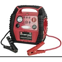
16547NV - Battery charger APA - Free user manual and instructions
Find the device manual for free 16547NV APA in PDF.


User questions about 16547NV APA
0 question about this device. Answer the ones you know or ask your own.
Ask a new question about this device
Download the instructions for your Battery charger in PDF format for free! Find your manual 16547NV - APA and take your electronic device back in hand. On this page are published all the documents necessary for the use of your device. 16547NV by APA.
USER MANUAL 16547NV APA
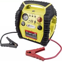
DE Power Pack 5 in 1
Art.-Nr. 16547NV
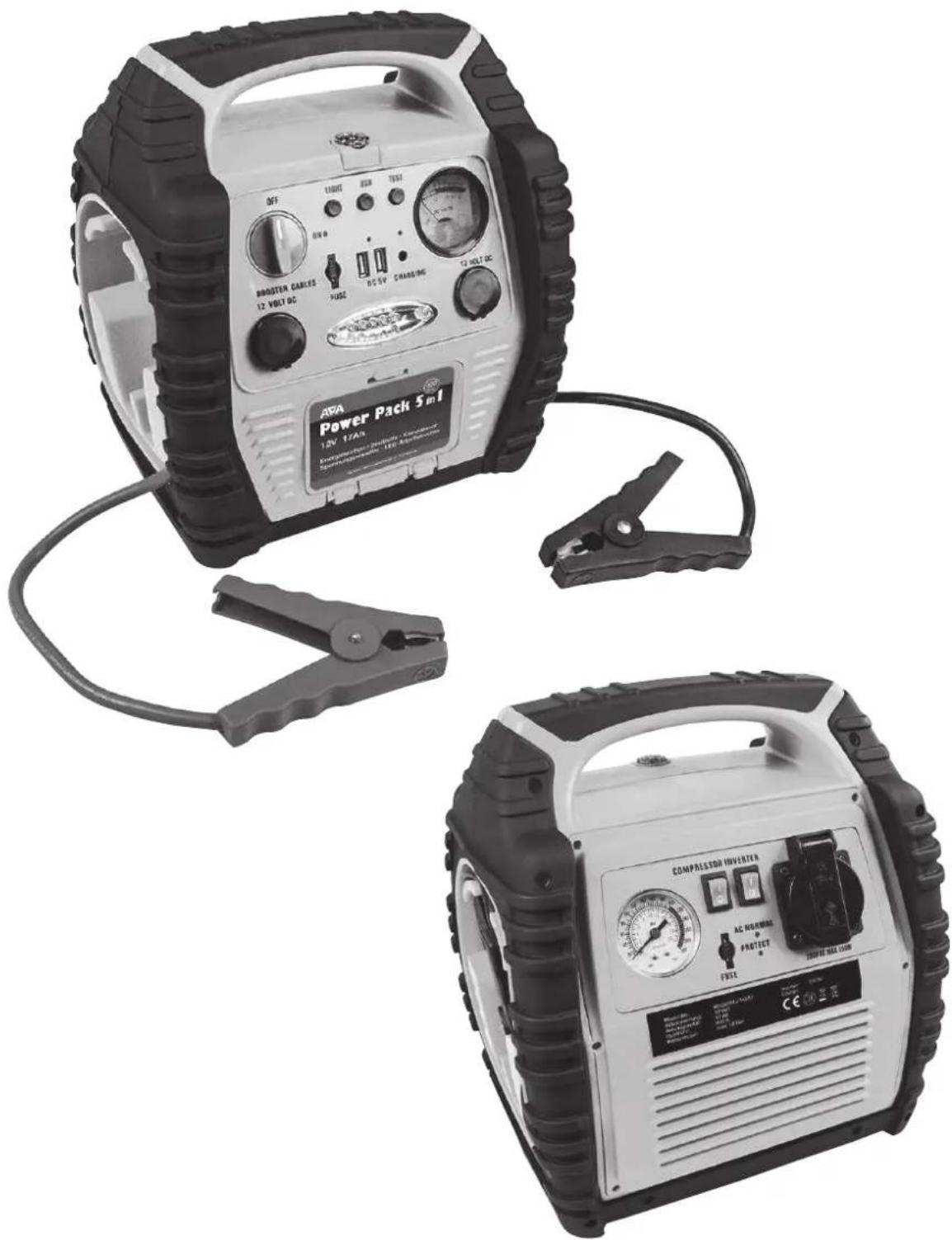
natural_image
Two portable power charging devices with labeled control knobs and gauges, shown from different angles (no visible text or symbols on the devices themselves)EAL GmbH
text_image
Labeled diagram of a portable electric vehicle with numbered parts for identification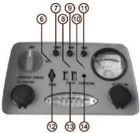
text_image
6 7 8 9 10 11 OFF START RESET THAT PULSE DC 5V CHARGING 12 WELT DC 13 WELT DC 14text_image
Labeled diagram of a portable electronic device with numbered components and warning text in Chinese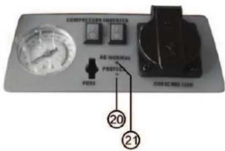
text_image
COMPRESSOR UNIVER 20 21natural_image
Close-up of a car tire with visible tread pattern and central valve (no text or symbols)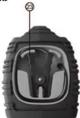
natural_image
Close-up of a car tire head with visible tread pattern and central vent (no text or symbols)text_image
Diagram showing labeled components of an appliance with numbered parts, including a power adapter, cable, and terminal connectors.text_image
DC VOLTUR CHARGINGnatural_image
Close-up of a black mechanical tool with a curved arrow indicating rotation (no text or symbols visible)natural_image
Close-up of a black tool with a handle and arrow indicating direction (no text or symbols)Bild 10
natural_image
Close-up of a black cable with a curved handle and a directional arrow indicating rotation (no text or symbols)natural_image
Close-up of a black mechanical tool with a curved handle and lever (no visible text or symbols)natural_image
Three different types of mechanical connectors or sensors, shown in grayscale without any text or symbols.26 27 28
GB 5-in-1 power pack
Item number 16547
Contents Page
- Proper use of the product 9
- Scope of delivery 10
- Specifications 10
- Safety precautions 10
- Explanation of symbols 10
- Operating instructions .... 11
6.1 Overview 11
6.1.1 Overview of front 11
6.1.2 Overview of rear 11
6.1.3 Overview of sides, left / right 11
6.1.4 Overview of accessories 12
6.2 Charging the power pack 12
6.2.1 Charging using the plug-in charger 12
6.2.2 Charging using the MV charger cable 12
6.3 Starting aid 13
6.3.1 Connecting the power pack 13
6.3.2 Attempting to start 13
6.3.3 Removing the power pack 13
6.4 Use as 12 V voltage supply 13
6.5 Use as a USB charger 13
6.6 Compressor 13
6.6.1 Filling a tyre using the car valve / Schrader valve 13
6.6.2 Use as a valve adapter 14
6.7 Fuse / Replacing a fuse 14
6.8 Voltage converter 14
6.8.1 Connecting an electrical device to the voltage converter 14
6.8.2 Replacing the fuse 14 - Maintenance and care 14
7.1 Maintenance 14
7.2 Care 15 - Notes regarding environmental protection 15
- Contact information 15
WARNING

Read the operating instructions through carefully prior to initial use and observe all of the safety notes!
Not observing such may lead to personal injury, damages to the device or your property!
Store the original packaging, the receipt and these instructions so that they may be consulted at a later date! When passing on the product, please include these operating instructions as well.
Please check the contents of package for integrity and completeness prior to use!
1. Proper use of the product
The Power Pack acts as a starting aid for vehicles with a 12 V on-board voltage network. The integrated compressor may also be used to pump up car tyres, bicycle tyres, balls etc. With the help of the voltage converter it is possible to operate simple 230 V electrical devices (bulbs, soldering irons etc., but not electronic devices) with a performance of up to 150 W. The device has two USB connections for charging mobile telephones, smartphones, tablet computers, MP3 players and similar devices. The 12 V sockets are used to supply small electrical devices with a consumption of a maximum of 100 W.
The incorporated lead battery is charged either with the plug charger or the 12 V motor vehicle charging cable.
This device is not designed to be used by children or persons with limited mental abilities or without experience and/or lack of required specialist knowledge. Keep children away from the device.
The device is not designated for commercial use.
Use according to the intended purpose also includes the observance of all information in these operating instructions, particularly the observance of the safety notes. Any other utilisation is considered to be contrary to the intended purpose and may lead to material damages or personal injuries. EAL GmbH assumes no liability for damage resulting from improper use.
2. Scope of delivery
- Power Pack
- Valve adapter for bicycle valves (Dunlop and Sclaverand)
- Plug charger
- Valve adapter for balls
- 12 V motor vehicle charging cable • Valve adapter for leisure items
- Operating instructions • Fuses, 15 A
3. Specifications
Nominal battery voltage: 12 V Voltage converter:
Rechargeable battery capacity: 17 Ah Voltage: 230 V
Maximum starter current: 400 A (max. 900A) Permanent performance: 150 W
Dimensions: 290 x 310 x 220 [mm]
Cable length: 450 mm
Weight: 8,155 kg USB output: 5 V, 1 A / 2,1 A
Compressor: max. 18 bar Plug charger: 15 V, 500 mA
4. Safety precautions

- The warning triangle labels all instructions important to safety. Always follow these otherwise you could injure yourself or damage the device.
• Children may not play with the device. - Cleaning and user maintenance may not be carried out by children without supervision.
- Do not treat packaging material carelessly. This may become a dangerous plaything for a child!
- Only use this product as intended!
- Do not manipulate or disassemble the device!
- For your own safety, only use accessories and spare parts that are stated in these instructions or that are recommended by the manufacturer!
- When using lead batteries, always wear protective goggles and clothing.
- Lead batteries contain aggressive, corrosive acids. Prevent skin and eyes from coming into contact with the lead battery fluids! Never dismantle the lead battery! Wash affected skin thoroughly using soap and water. If acid has entered an eye, rinse immediately for at least 10 minutes under clean, running, lukewarm water! Then immediately consult a doctor!
- If there is acid on your clothing, rinse immediately with plenty of soap and water!
- Never wear rings, necklaces, watches or similar when handling batteries or chargers. The short-circuiting of the battery contacts brings a risk of burns and explosion!
- The Power Pack is only designed as jump start assistance for a vehicle that has a battery of its own. The Power Pack cannot replace the vehicle battery.
- Always store the pole callipers in the designated holders to ensure that the Power Pack is not at risk of short-circuiting when not in use.
- Do not attempt to remove and replace the battery pack of the Power Pack. If the battery comes to the end of its useful life, dispose of the entire in accordance with your local guidelines.
- Never charge the Power Pack using a damaged charger.
- Only used the supplied accessories to charge the Power Pack.
- Never attempt to start a vehicle when the battery is frozen, this brings a risk of explosion.
- Always observe the following sequence when disconnecting the Power Pack from the battery. There is a risk of explosion: First disconnect the black (-) pole calliper, coil the cable and attach the pole calliper to the designated holder. Then disconnect the red (+) pole calliper, coil the cable and attach the pole calliper to the designated holder.
- Keep the air vent for the voltage converter, on the back of the device, free. The voltage converter may otherwise overheat and then there is a risk of fire.
5. Explanation of symbols

Corresponds to EC directives
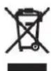
Labelled electrical products may not be disposed of in the household waste

Devices with this symbol may only be operated indoors (dry environment)

Insulated housing (protection class II).
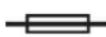
Fuse,
here: 1.0 A
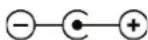
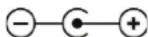
Polarity of the plug connector

Read the operating instructions

Corresponds to the requirements of § 21 of the German Product Safety
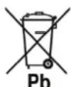
Labelling according to § 17 BattG (German battery laws): The end consumer is obliged to send to the dealer for proper disposal or to hand in at an appropriate collection point.
- Operating instructions
6.1 Overview
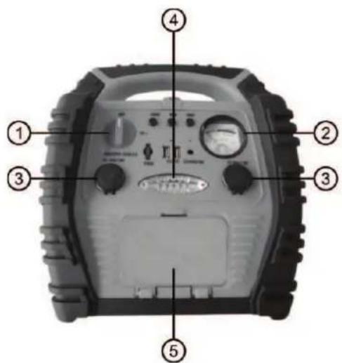
6.1.1 Overview of front
text_image
Labeled diagram of a portable electric vehicle with numbered parts for identification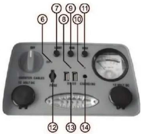
text_image
6 7 8 9 10 11 UNITER CABLES 12 MOLT DC FROSE ON 5V CHARGING 13 MOLT DCFigure 1: Overview of front
1 Starting aid switch 8 Control lamp for USB connections
2 Voltmeter (charge status) 9 Switch for USB connections
3 12 V socket 10 Charging control lamp
4 LED-lamp 11 Control button for charging state
5 Storage compartment for air hose 12 Fuse
6 Control lamp for starting aid 13 USB connections
7 Switch for LED lamp 14 Charging sockets
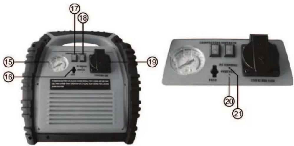
6.1.2 Overview of rear
text_image
Technical diagram of an electronic device with numbered components and labeled parts in ChineseFigure 2: Overview of rear
15 Manometer 19 230 V AC socket
16 Fuse for voltage converter 20 Warning lamp for voltage converter
17 Switch for compressor 21 Control lamp for voltage converter
18 Switch for voltage converter
6.1.3 Overview of sides, left/right
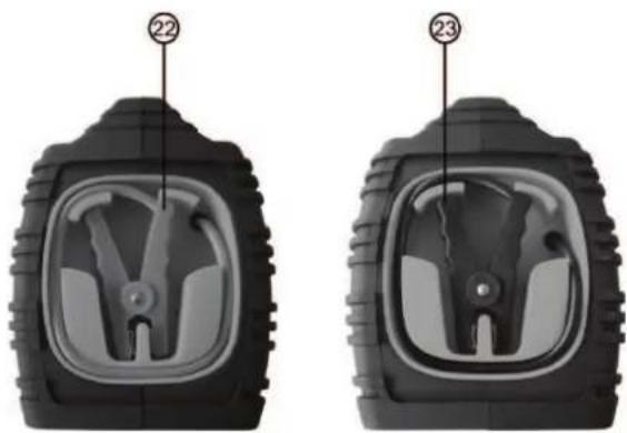
natural_image
Two identical black tire components with internal gear-like cutouts, labeled 22 and 23 (no text or symbols on the parts themselves)22 Pole callipers, red (+)
23 Pole callipers, black (-)
Figure 3: Overview of sides, left/right
6.1.4 Overview of accessories
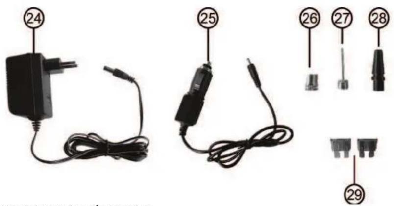
text_image
24 25 26 27 28 29 Figure 4. Section of chargerFigure 4: Overview of accessories
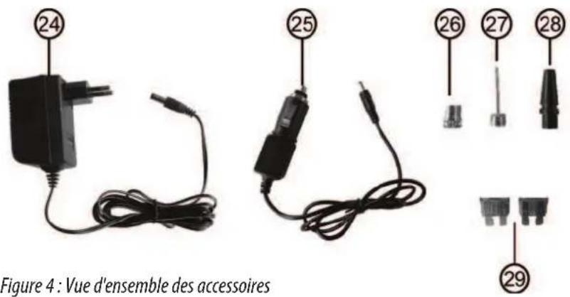
24 Plug charger 27 Valve adapter for balls
25 12V motor vehicle charging cable 28 Valve adapter for leisure items
26 Valve adapter for bicycle valves 29 Replacement fuses, 15 A
(Dunlop and Sclaverand)

CAUTION:The fuses must be inserted prior to initial use.
On the front, see position 12 in the overview.
On the rear, see position 16 in the overview.
6.2 Charging the Power Pack:
Charge the Power Pack fully after purchase or before using for the first time for 72 hours. Then leave the Power Pack connected to the charger for a maximum of 48 hours. Press the control button for the charge status (Position 11 in the overview). If the voltmeter for the charge status (Position 2 in the overview) shows a value of 50% or less, yellow section (Figure 5), then the Power Pack must be charged. If the value is over 50%, green section (Figure 6), the Power Pack is ready for use.
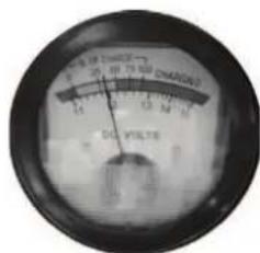
text_image
8.5 V THI/2 F 20 10 75 90 DM/DE 2 DIF FILTER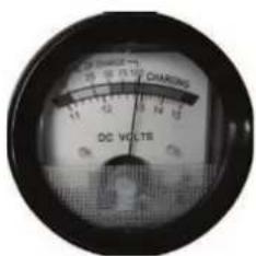
text_image
DC VOLTs CHARGINGFigure 5: Battery must be charged Figure 6: Battery is fully charged
6.2.1 Charging using the plug charger:
Rotate the switch for the starting aid (Position 1 in the overview) to the „AUS/OFF" setting. Switch off the voltage converter, the compressor and the working light. Plug the coaxial connector of the plug charger (Position 24 in the overview) into the charging socket of the Power Pack (Position 14 in the overview). Now, connect the plug charger with the mains socket. The charge control lamp (Position 10 in the overview) now lights up. If the battery is completely empty, the charging process will take approximately 34 hours. After charging, first disconnect the plug charger from the mains socket, then disconnect the coaxial connector from the charging socket of the Power Pack. If you now press the control button for the charge status (Position 11 in the overview), the Voltmeter shows a voltage of approximately 13 V for the charge status (Position 2 in the overview).

Never leave the plug charger connected for longer than 48 hours!
6.2.2 Charging using the 12 V motor vehicle charging cable:
Rotate the switch for the starting aid (Position 1 in the overview) to the „AUS/OFF" setting. Switch off the voltage converter, the compressor and the working light. Plug the coaxial connector of the 12 V motor vehicle charging cable (Position 25 in the overview) into the charging socket of the Power Pack (Position 4 in the overview). Now connect the 12 V plug to the 12 V socket of your vehicle. The charge control lamp (Position 10 in the overview) now lights up. If the battery is completely empty, the charging process will take approximately 12 hours. After charging, first disconnect the 12 V plug from the 12 V socket of your vehicle and then disconnect the coaxial connector from the charging socket of the Power Pack. If you now press the control button for the charge status (Position 11 in the overview), the Voltmeter shows a voltage of approximately 13 V for the charge status (Position 2 in the overview).

CAUTION: Only charge the Power Pack when driving or when the motor is running, otherwise there is a risk that the starter battery of your vehicle may be discharged.
6.3 Starting aid:
Disconnect all of the devices connected to the Power Pack from the 12 V outlet sockets (Position 3 in the overview) and from the socket (Position 19 in the overview) of the voltage converter and the USB connections (Position 13 in the overview).
Make sure that the Power Pack is fully charged. To do this, press the control button for the charge status (Position 11 in the overview). If a charge status between 50% and 100% is shown, the Power Pack is ready for use.
6.3.1 Connecting the Power Pack (vehicles with negative earth):
Switch off the ignition and all electrical consumers of the vehicle (radio, lights, rear window heating, seat heating etc.). Apply the parking brake. Rotate the switch for the starting aid function (Position 1 in the overview) to the „AUS/OFF“ setting. First connect the red (+) pole callipers (Position 22 in the overview) to the plus terminal of your vehicle battery. The black (-) pole callipers (Position 23 in the overview) is connected, as far as possible from the battery, to the motor block or chassis (not to a painted part). If the Power Pack has been connected correctly, the control lamp for the starting aid (Position 6 in the overview) lights in green. If this is not the case, the control lamp lights in red and an acoustic warning is issued. In this case, check the connections of the pole callipers and correct. Now rotate the switch for the starting aid to the „EIN/ON“ position.
6.3.2 Attempting to start:
Start the motor. Do not operate the starter for longer than 6 seconds. The battery of the Power Pack is not designed for longer starting attempts. Pause for at least 5 minutes between two starting attempts. If the motor does not start after a number of attempts, abort the process and investigate the cause of the defect.
6.3.3 Removing the Power Pack:
Rotate the switch for the starting aid function to the "AUS/OFF" setting. First disconnect the black (-) pole calliper, coil the cable and attach the pole calliper to the designated holder. Then disconnect the red (+) pole calliper, coil the cable and attach the pole calliper to the designated holder. Always maintain this sequence.
Recharge the Power Pack.
6.4 Use as 12 V voltage supply:
The Power Pack can be used as a 12 V direct current source for many devices that can be operated with 12 V direct current and a cigarette lighter plug. Plug the cigarette lighter plug of the device you wish to operate into one of the 12 V outlets (Position 3 in the overview). The device you wish to operate should not require a current greater than 10 A.
6.5 Use as a USB charger
Thanks to the two USB connections, the Power Pack may also be used as a charger for mobile telephones, smartphones, tablets, MP3 players and similar devices. To recharge a USB device, first connect it with the associated charging cable (not included in the scope of delivery). Plug the USB connector of the charging cable into one of the two USB outlets (Position 13 in the overview). Start charging by switching on the USB connections using the switch (Position 9 in the overview). You can tell whether the USB connections are switched on using the lighting of the control lamp (Position 8 in the overview).
6.6 Compressor:
In order to be able to work with the compressor, first remove the air hose from the storage compartment (Position 5 in the overview).
6.6.1 Filling a tyre using the car valve (Schrader valve)
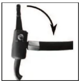
Open the lock on the valve connection
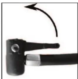
natural_image
Close-up of a black mechanical tool with a curved arrow indicating rotation (no text or symbols visible)Place the valve connection on the valve
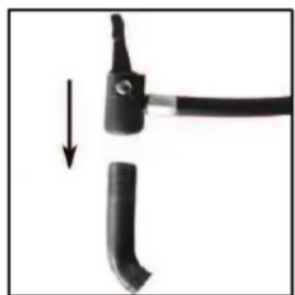
natural_image
Close-up of a black tool with a curved handle and a cable, showing a downward arrow indicating motion (no text or symbols)Lock the valve connection You can now fill the tyres using the compressor
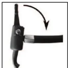
natural_image
Close-up of a black mechanical component with a curved arrow indicating rotation or movement (no text or symbols)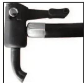
natural_image
Close-up of a black tool handle with curved grip and metallic lever (no text or symbols visible)Figure 7 Figure 8 Figure 9 Figure 10
To fill, switch the compressor on using the switch (Position 17 in the overview).
The manometer (Position 15 in the overview) is used to give a rough approximation of the air pressure. When the desired air pressure is reached, switch the compressor off. Remove the valve connection in reverse order (Figures 10 - 7).

When filling, always pay attention to the correct air pressure (consult the operating instructions of your vehicle for information). The compressor is able to supply of pressure of up to a maximum of 18 bar. If the pressure is too high, there is a risk of explosion and injury.

Never allow the compressor to operate for longer than 10 minutes without a pause, otherwise there is a risk of overheating. Switch the compressor off after 10 minutes of use and allow it to cool down fully before starting it up again.
Never leave the compressor to operate unattended.
After filling a tyre, check the tyre pressure again using a separate air pressure tester (e.g. at a filling station, vehicle workshop).
6.6.2 Using the valve adapter:
natural_image
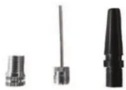
Three mechanical components: threaded fastener, cylindrical rod, and conical tip (no text or symbols visible)26 Bicycle valve adapter (for Dunlop and Sclaverand valves)
27 Adapter for balls
28 Universal adapter for leisure items (inflatable toys etc.)
26 27 28
Figure 11: Valve adapter
Bicycle valve adapter (for Dunlop and Sclaverand valves) (26):
For Sclaverand valves: Undo the knurled screw of the valve piston and push down briefly once.
Screw the valve adapter, using the knurled crown, down onto the bicycle valve.
Now connect the air hose, as shown on Figures 7 – 10, to the bicycle valve adapter. Now you can switch on the compressor and fill the bicycle tyre. When the desired air pressure is reached, switch the compressor off. Remove the valve connection in reverse order (Figures 10 – 7). Unscrew the bicycle valve adapter and remove from the bicycle valve.
For Sclaverand valves: Tighten the knurled screw of the valve piston up again.
Adapter for balls (27):
Open the lock of the valve connection (Figure 7). Insert the adapter for balls into the valve connection. Lock the valve connection (Figure 9). Insert the adapter into the valve of the ball. Now you can switch on the compressor and fill the ball. When the desired air pressure is reached, switch the compressor off. Remove the adapter from the valve connection by proceeding in reverse order, as described above.
Universal adapter for leisure items (28):
Open the lock of the valve connection (Figure 7). Insert the universal adapter into the valve connection. Lock the valve connection (Figure 9). Insert the universal adapter into the filling connection of your leisure equipment. Depending on version, it is possible that the universal adapter will need to be held firmly during the filling process. Now you can switch on the compressor and start the filling process. When the desired air pressure is reached, switch the compressor off. Remove the adapter from the valve connection by proceeding in reverse order, as described above.
6.7 Fuse / Replacing a fuse
The compressor, the 12 V outlet sockets, the USB connections and the working light are secured via a shared 15 A fuse (Position 12 in the overview). If this fuse is triggered, switch off the compressor and the working light. Disconnect all of the devices connected to the 12 V outlet sockets and the USB connections. Remove the defective fuse from the holder. Replace the defective fuse with another of the same quality, here a flat 15 A fuse.
6.8 Voltage converter

The continuous rating of the voltage converter is 150 W. When connecting an electrical device to the voltage converter, pay attention to ensure that the top performance of this device does not exceed the 150 W continuous rating of the voltage converter.
6.8.1 Connecting an electrical device to the voltage converter
Switch the voltage converter off using the switch (Position 18 in the overview) before connecting an electrical device. Switch off the electrical device you intend to connect before connecting it to the voltage converter. Plug the plug of the electrical device into the socket (Position 19 in the overview) of the voltage converter. Switch the voltage converter off using the switch. The control lamp (Position 21 in the overview) of the voltage converter lights green and the fan will start operating. Now you can start to use the connected device.
If the red warning lamp (Position 20 in the overview) of the voltage converter lights up, the battery performance of the Power Pack is not sufficient to operate an electrical device on the voltage converter. In this case, switch the voltage converter, the electrical device and all other functions of the Power Pack off. Pull the plug out of the socket. Recharge the Power Pack

Never operate the voltage converter while the Power Pack is being charged.
6.8.2 Replacing the fuse
The voltage converter has a fuse for its own protection (Position 16 in the overview). The fuse is triggered if the connected electrical devices attempts to draw too much power from the voltage converter. If this fuse has been triggered, first switch off the connected device and then switch off the voltage converter. Pull the plug of the device from the socket of the voltage converter. Replace the defective fuse with another of the same quality, here a flat 15 A fuse.
7. Maintenance and care
7.1 Maintenance: Store the Power Pack in a dry, frost-free place. If the Power Pack is not used for a longer period of time, it must be recharged. In winter, recharge every two months, in summer recharge every month.
7.2 Care: Switch the Power Pack off before cleaning. Clean the housing of the Power Pack with a soft, dry cloth. Do not use any aggressive cleaning agents or solvent-based cleaners. Never allow liquids to ingress into the housing.
8. Notes regarding environmental protection
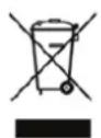
Do not dispose of electrical devices with the household waste! Electrical and electronic scrap must be collected separately and disposed of in an environmentally responsible manner for recycling. Please contact your community or city administration regarding disposal options for electrical and electronic scrap.
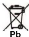
You are legally obliged to return batteries and battery packs. After use, they may be returned to us, handed in to a communal collection point, or to a local dealer. Batteries containing hazardous materials are labelled with a symbol consisting of a crossed out trash can and the chemical symbol (Cd, Hg or Pb) which designates the heavy metal responsible for the hazard.
9. Contact information
EAL GmbH
text_image
Labeled diagram of a mobile phone or remote control device with numbered parts for identification.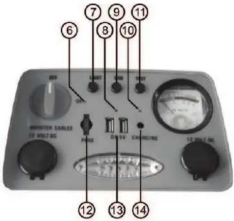
text_image
6 7 8 9 10 11 OFF LND DC TEST DINJECTOR CARLES 10 VOLT-DC PANSS DB/SV EXAMOUNTING 10 VOLT-DC 12 13 14text_image
Labeled diagram of an industrial air conditioning device with numbered components and a warning label below.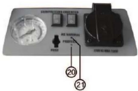
text_image
COMPRETOLEREN PRICE RES. NORMAL PROFEET STOCK NO WMK TINCE 20 21natural_image
Two identical black tire components with visible internal features, labeled 22 and 23 (no text or symbols on the parts themselves)22 Pince crocodile, rouge (+)
6.1.4 Overview of accessories
natural_image
Close-up of a black mechanical tool with a curved arrow indicating rotation (no text or symbols)Figure 7 Figure 8 Figure 9

natural_image
Close-up of a black tool with a handle and arrow indicating direction (no text or symbols)Figure 10
natural_image
Close-up of a black mechanical component with a curved arm and arrow indicating rotation (no text or symbols)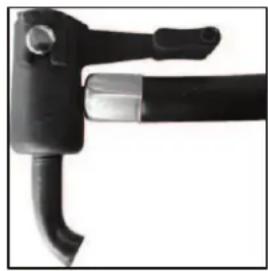
natural_image
Close-up of a black mechanical tool with curved handle and lever (no visible text or symbols)natural_image
Three black plastic screwdrivers with numbered labels (26, 27, 28) on the left, no other text or symbols present.NL Power Pack 5 in 1
Art.nr. 16547
Inhoud Pagina
text_image
Labeled diagram of a tracked robot with numbered parts for identification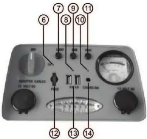
text_image
6 7 8 9 10 11 RESETER CABLES 12 VOLT DC FUSE ON SVD CHINESE 13 VOLT DC 14natural_image
Two identical black tire components with visible internal features, labeled 22 and 23 (no text or symbols on the parts themselves)22 Pooltang rood (+)
natural_image
Close-up of a black mechanical tool with a curved arrow indicating motion (no text or symbols)natural_image
Close-up of a black tool with a handle and a curved blade, showing a downward arrow (no text or symbols)natural_image
Close-up of a black mechanical component with a curved handle and arrow indicating rotation (no text or symbols)natural_image
Close-up of a black tool with curved handle and lever (no visible text or symbols)natural_image
Three different types of screwdrivers shown in grayscale (no text or symbols visible)IT Power Pack 5 in 1
Cod. art. 16547
Indice Pagina
Fusibile, qui: 1,0 A
text_image
① ② ③ ④ ⑤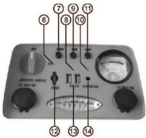
text_image
6 7 8 9 10 11 UNIT DENT USB TSS S S SWATER CABLES 12 VOLT-DC FUSE ON-SW CHARGING 13 VOLT-DC 12 VOLT-DCtext_image
Technical diagram of an electronic device with numbered components and labeled parts in Chinesenatural_image
Close-up of a black mechanical tool with a curved arrow indicating rotation (no text or symbols visible)natural_image
Close-up of a black tool with a handle and a curved blade, showing a downward arrow (no text or symbols)natural_image
Close-up of a black mechanical component with a curved arrow indicating rotation or movement (no text or symbols)natural_image
Close-up of a black mechanical tool with curved handle and lever (no visible text or symbols)Figura 7 Figura 8 Figura 9 Figura 10
natural_image
Three different types of mechanical connectors or sensors, shown in grayscale without any text or symbols.We herewith confirm that the appliance as detailed below complies with the mentioned directives.
Artikelbezeichnung:
Power Pack 5 in 1
Article description:
Artikelnummer:
16547NV
Article number:
Type:
NFQ0901
Firmenanschrift:
governing EU-directives:

- RoHS 2 Restriction of Hazardous Substance 2011/65/EU
harmonised EN-Standards
Dieser Artikel entspricht folgenden, zur Erlangung des CE-Zeichens erforderlichen Normen: The article complies with the standards as mentioned below which are necessary to obtain the CE-symbol:
zu 1. EN 55014-1:2006+A1:2009+A2:2011
zu 2. EN 60335-1:2012 EN 62233:2008
EN 55014-2:1997+A1:2001+A2:2008
EN 55022:2010
EN 55024:2010
EN 61000-3-2:2014
EN 61000-3-3:2013
EN 61000-6-1:2007
EN 61000-6-3:2007+A1:2011
zu 3.
zu 4. EN 50581:2012
(EN62321:2009, IEC 62321)
Firmenstempel company stamp

text_image
GERMANY EAL camping, car & bicycle accessories
EAL GmbH