USER MANUAL Easy Chem HAYWARD
natural_image
Abstract geometric logo with stylized letter H inside a circular frame (no text or symbols)
HAYWARD®
natural_image
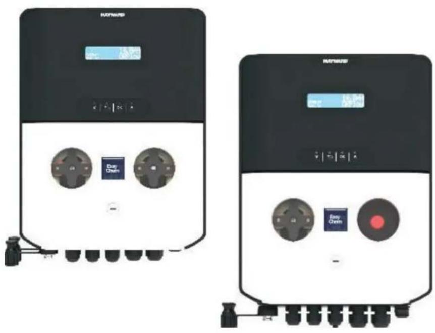
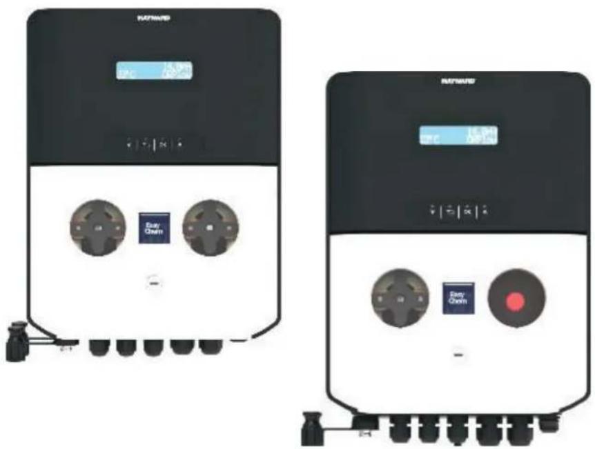
Two identical black-and-white industrial control units with buttons and dials, no visible text or symbols on the devices themselves.
CE EAC UK CA

natural_image
Two line icons: one open with an information symbol, the other closed with an open book (no text or symbols present)
OWNER'S MANUAL

natural_image
Abstract geometric logo with stylized letter H inside a circular frame (no text or symbols)
HAYWARD®

natural_image
Two black industrial control panels with buttons and indicators, no visible text or symbols on the surfaces.
CE EAC UK CA

natural_image
Two line icons: one open with an information symbol, the other closed with an open book (no text or symbols present)
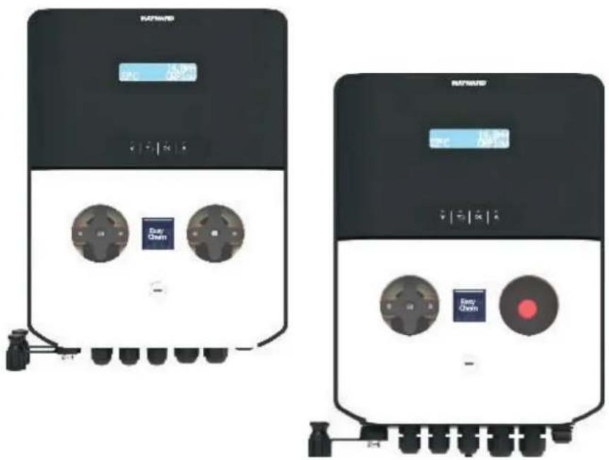
EasyChem Double and Plug version | pH · ORP
OWNER'S MANUAL
PLEASE KEEP THIS MANUAL FOR FUTURE REFERENCE
⚠ WARNING – Carefully read the instructions that appear in this manual and on the device. Failure to comply with the instructions can cause injuries. This document must be given to every pool user, who should keep it in a safe place.
⚠ WARNING – Disconnect the equipment from the mains supply before any intervention.
⚠ WARNING – All electrical connections must be carried out by a qualified approved electrician in accordance with the standards currently in force in the country of installation or, failing this, in accordance with the international standard IEC 60334-7-702.
| F NF C 15-100 GB BS7671:1992 | | |
| D DIN VDE 0100-702 EW SIST HD 384-7-702.S2 | | |
| A ÖVE 8001-4-702 H MSZ 2364-702:1994 / MSZ 10-533 1/1990 | | |
| E UNE 20460-7-702 1993, REBT ITC-BT-31 2002 M MSA HD 384-7-702.S2 | | |
| IRL IS HD 384-7-702 PL TS IEC 60364-7-702 | | |
| I CEI 64-8/7 CZ CSN 33 2000 7-702 | | |
| LUX 384-7.702 S2 | SK STN 33 2000-7-702 |
| NL NEN 1010-7-702 | SLO SIST HD 384-7-702.S2 |
| P RSIUEE | TR TS IEC 60364-7-702 |
⚠ WARNING – Check that the device is plugged into a power outlet that is protected against short-circuits. The device must also be powered via an isolating transformer or a residual current device (RCD) with a nominal operating residual current not exceeding 30 mA.
⚠ WARNING – Ensure that children cannot play with the device. Keep your hands and any foreign object away from openings and moving parts.
⚠ WARNING – Check that the supply voltage required by the product corresponds to the voltage of the distribution network and that the power supply cables are suitable for the product power supply.
⚠ WARNING – Chemicals can cause internal and external burns. To avoid death, serious injury and/or damage to equipment, wear personal protective equipment (gloves, goggles, mask, etc.) when servicing or maintaining this device. This device must be installed in an adequately ventilated place.
⚠ WARNING – The unit shall not be operated when there is no water flow in the cell.
⚠ WARNING – To reduce the risk of electric shock, do not use an extension cable to connect the device to the mains. Use a wall socket.
⚠ WARNING – Use, cleaning or maintenance of the device by children over 8 years of age or by people with impaired physical, sensory or mental capacities, or a lack of experience or expertise, should only take place once they have received appropriate instruction and under adequate supervision of an adult who is responsible for them, to ensure the device is handled safely and avoid all risk of danger.
⚠ WARNING – Use only original Hayward® parts.
⚠ WARNING – If the power supply cable is damaged, it must be replaced by the manufacturer, the after-sales service or similarly qualified persons to avoid danger.
⚠ WARNING – The device must not be used if the power cord is damaged. An electric shock could occur. A damaged power cord must be replaced by the after-sales service or similarly qualified persons to avoid danger.
INDEX
- General
- Pack contents
- Installation
3a. View of overall installation
3b. Wall-mounted installation
3c. Installation of pH and ORP probes, and acid dosing pump
- Electrical connections
4a. Electrical installation and wiring
4b. Electrical suppressor device
4c. Trigger input by circulation pump
-
Specifications
-
Setup and Operation
6a. Description of the home screen and defaults parameters
6b. Main menu
6c. View parameters
6d. Standby system
6e. Reset OFA Timer
6f. pH probe calibration
6g. ORP probe calibration
6h. Temperature probe calibration
- Dosing method
- Alarms
- Servicing
- Troubleshooting guide
- Environmental information
1. GENERAL
Before carrying out ANY work inside control panel of the EasyChem Double device, make sure you disconnect it from the power supply.
Failure to comply with the instructions contained in this manual could cause injury to people and/or damage to the appliance and the system.
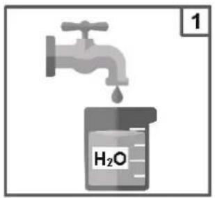
2. PACK CONTENTS
A: PVC Crystal 4x6 suction hose (4 m)
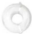
B: Polyethylene delivery hose (5 m)
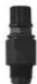
C: FPM Lip valve (3/8" GAS)

F: Reducer for injection valve (1/2" M to 3/8" F)
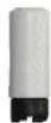
G: Foot filter (PP riser)
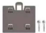
H: Mounting bracket kit (ø=6 mm screws)
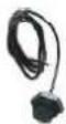
L: Temperature sensor
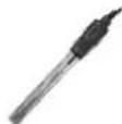
M: pH probe
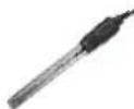
N: ORP probe
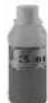
O: pH 4 Buffer solution
P: pH 7 Buffer solution
Q: 465 mv Calibration solution

R: Water S: Nuts for peristaltic tube

| Item*\System | EASY-CH-DPHRXG EASY-CH-DPHRXGS |
| A | 2 | 1 |
| B | 2 | 1 |
| C | 2 | 1 |
| D | 2 | 2 |
| E | 5 | 4 |
| F | 2 | 1 |
| G | 2 | 1 |
| H | 1 | 1 |
| L | 1 | |
| M | 1 | 1 |
| N | 1 | 1 |
| O | 1 | 1 |
| P | 1 | 1 |
| Q | 1 | 1 |
| R | 1 | 1 |
| S | 2 | 1 |
*NOTE: The values from the table represent the number of items inside the package.
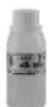
3. INSTALLATION
3a. View of overall installation
flowchart
graph TD
    A["①"] --> B["②"]
    B --> C["③"]
    C --> D["④"]
    D --> E["⑤"]
    E --> F["⑥"]
    F --> G["⑦"]
    G --> H["⑧"]
    H --> I["⑨"]
    I --> J["⑩"]
    J --> K["⑪"]
    K --> L["⑫"]
    L --> M["⑬"]
    M --> N["⑭"]
    N --> O["⑮"]
    O --> P["⑯"]
    P --> Q["⑰"]
    Q --> R["⑱"]
    R --> S["⑲"]
    S --> T["⑳"]
    T --> U["㉑"]
    U --> V["㉒"]
    V --> W["㉓"]
    W --> X["㉔"]
    X --> Y["㉕"]
    Y --> Z["㉖"]
- Pool
- Circulation pump
- Acid
- Chlorine
- Filter
- Heat exchanger
- pH probe
- ORP probe
- Temperature sensor
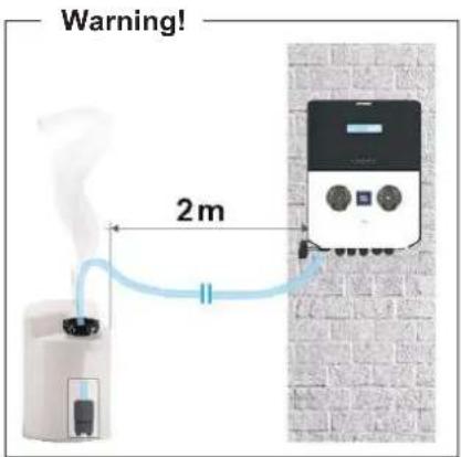
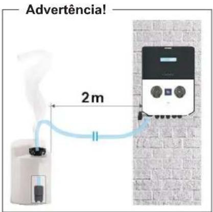
Warning!
Use with salt chlorinator:
For the pH systems, to prevent the risk of system malfunctioning or damage, observe the following instructions:
- Position the pH measuring probe prior to the chlorinator cell.
- To eliminate eddy currents, connect the pool water to an electrical ground point
- Position the product injection point after the chlorinator cell.
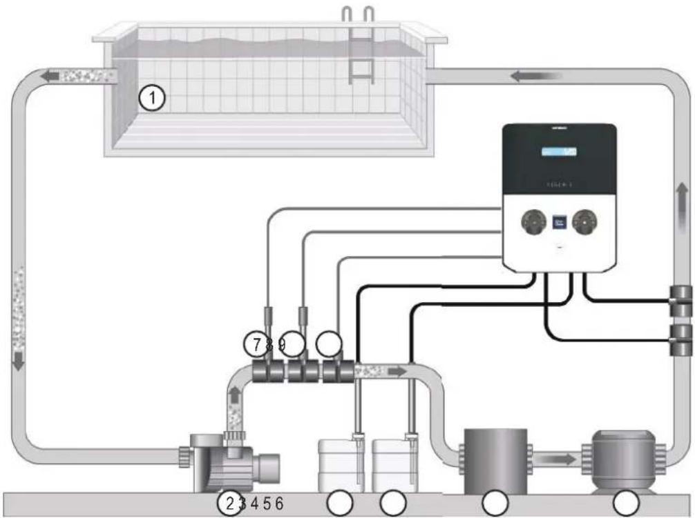
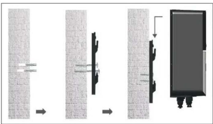
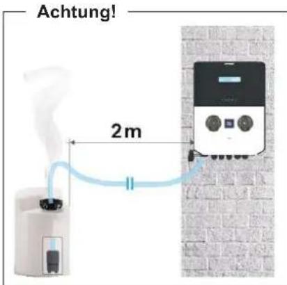
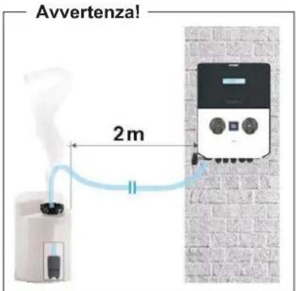
3b. Wall-mounted installation
Mount the control box on the wall. The box must be installed in the equipment room (dry, temperate, ventilated). Caution, acid vapours can cause irreversible damage to your device. Position the treatment product tanks accordingly.
Unplug the pool filter pump before you begin the installation. The installation must be performed in compliance with the regulations in effect in the country of installation.
natural_image
Diagram showing four sequential steps of a mechanical or structural assembly with arrows indicating direction (no text or symbols present)
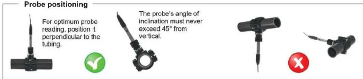
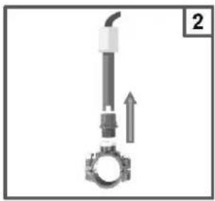
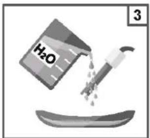
3c. Installation of pH and ORP probes, and acid dosing pump
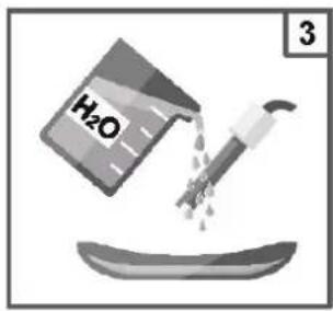
The pH and ORP probes are «wet» packed and protected by a plastic cap. The probes must always remain wet. If the probes are allowed to dry, they will be permanently unusable (not covered by the warranty) and the pH-ORP test kit will be ineffective.
Remove the pH and ORP probes from their plastic protective caps and set the caps aside for later use (wintering). Insert the probes into the double probe holder and tighten to ensure they are watertight. Connect the probe holder to the valves screwed onto the saddle clamps and tighten by hand only. Check that the probes are watertight at startup. Seal with Teflon, if required.
After installation, check that the probes are constantly in contact with the water in the pool. When the filtration pump is not running (even for long periods), the water remaining in the chamber may be sufficient to protect the probes.
4. ELECTRICAL CONNECTIONS
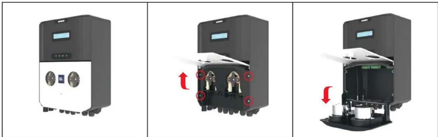
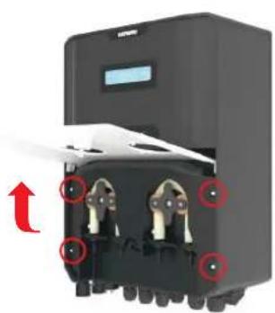
4a. Electrical installation and wiring
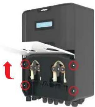
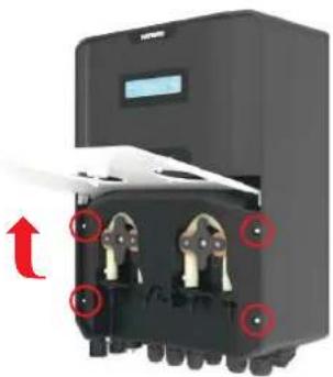
Connect the EasyChem Double to a permanent power outlet.
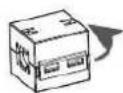
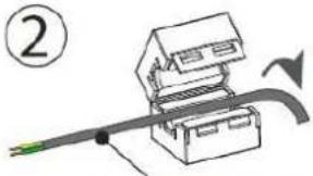
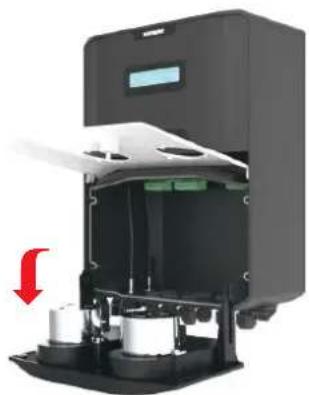
Open the peristaltic pump lid (1), unscrew four screws (2) and pull the peristaltic pump on the side (3), as illustrated in the pictures below:
natural_image
Three-panel diagram showing a device with control panel, internal components, and external casing (no text or symbols)
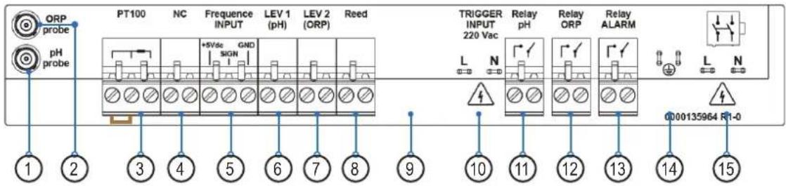
Label connection:
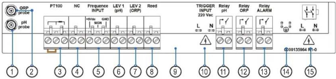
| Clamp | Description | EASY-CH-DPHRXG / EASY-CH-DPHRXGS | Wire connection details |
| 1 Input Probe pH pH Probe | | |
| 2 Input Probe ORP ORP Probe | | |
| 3 Input Probe | TEMPERATURE SENSOR (PT100)A= two wires sensor, probe included in the packageB= three wires sensor, please check the optional colors probe | 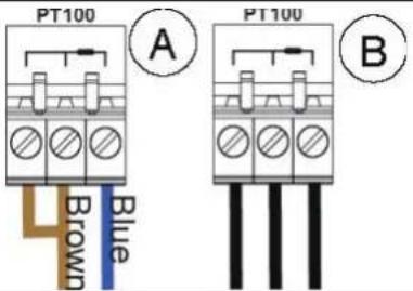 |
| 4 Input Probe Not used | | --- |
| 5 | Frequency input by water meter pulse sender | Flow Rate (Freq. Input)A= Mechanical reedB= Padwheel hall sensor | 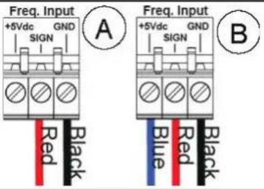 |
| 6 Level (product tank) pH Level probe Level probe for chemical tank | |
| 7 Level (product tank) Chlorine (ORP) level probe Level probe for chemical tank | |
| 8 Level (Reed sensor) Flow (External REED flow sensor) Flow sensor | |
| 9 Serial Port | Not present | --- |
| 10 | Trigger Input 220Vac (High Voltage) | Circulation Pump (220Vac input) | Line/Neutral wires |
| 11 | Output Relay R1 (AUX1) | RL1 AUX1 pH | Dry contact |
| 12 | Output Relay R2 (AUX2) | Easy-CH-DPHRXG:RL2 AUX2 OPREasy-CH-DPHRXGS:RL2 AUX2 OPR with Schuko socket | Dry contact |
| 13 | Output Relay R3 | RL3 Alarm | Dry contact |
| 14 | Earth connector | Earth | --- |
| 15 | Power Supply | 220-240 Vac 50-60 Hz (F/N) | --- |
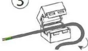
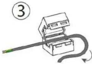
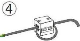
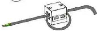
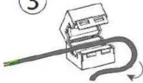
4b. Electrical suppressor device
It is mandatory to install the coil suppressor, please see the instructions below:
①
②
natural_image
Diagram of a mechanical assembly with a lever and pulley, no visible text or symbols
POWER SUPPLY CABLE
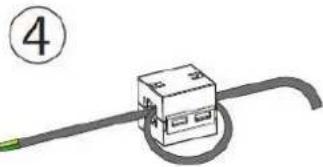
③
natural_image
Simple line drawing of a mechanical device with a curved cable and a green cable (no text or symbols)
④

WRAP THE CABLE FOR A TURN
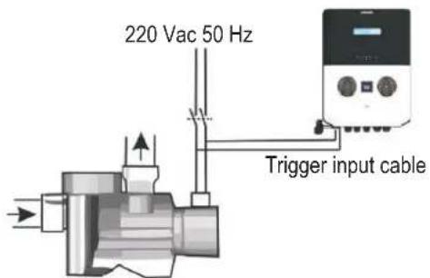
Circulation pump
Connect the Trigger cable as the example on the site with the traditional circulation pump, to check the flow is present in the pipe line.
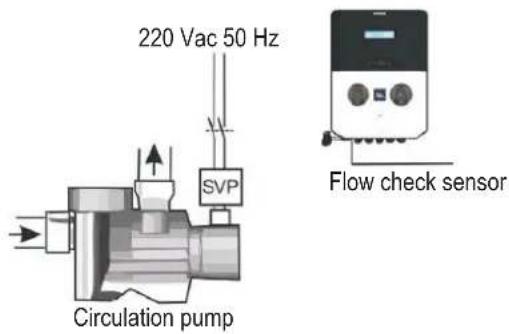
Do not use the Trigger cable to the circulation pump if the SVP (speed variable pump) is present, but use the Flow check sensor, pay attention to disable or enable the function in the setting menu.
5. SPECIFICATIONS
| Specifications EASY-CH-DPHRXG / EASY-CH-DPHRXGS |
| Range 0-14pH; -99 -1000mV; 0...+55°C | |
| Accuracy ±0.02pH, ±3mV; ±0.5°C | |
| Device precision ± 0.1 pH; ±10mV; ±1°C | |
| Flow rate pump (l/h) 1.5 l/h | |
| Flow rate pump (SPA model only) 1.5 l/h | |
| Power supply 220-240 VAC 50-60 Hz | |
| Consumption (W) 28 Watt | |
| Probe calibration Automatic | |
| Pump state Pause – Supply | |
| Max. back-pressure 1.5bar | |
| Relay contact (number 3) 250 Vac 10A (resistive load) |
| Fuse | 500 mA (fast) |
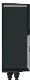
| Weight | 3.5 Kg |
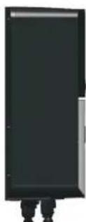
| Dimensions (W–H–D) | 212 x 303 x 113 mm |
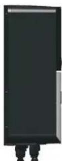
natural_image
Back view of a black electronic device casing with mounting holes and internal grid patterns (no visible text or symbols)
natural_image
Simple black rectangular object with two vertical legs at the bottom, no visible text or symbols.
natural_image
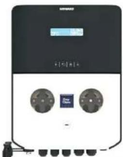
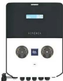
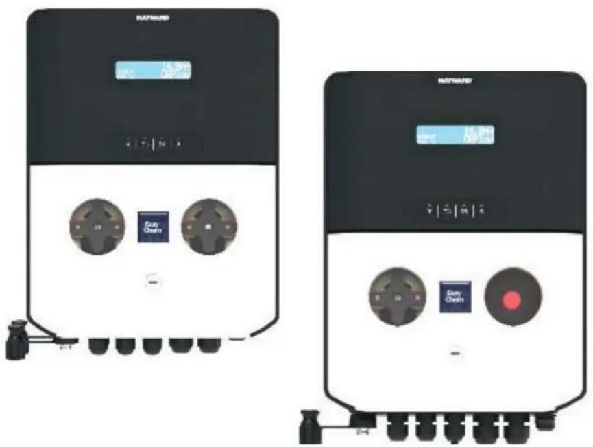
Front view of a black industrial electrical control unit with two circular buttons and a digital display (no visible text or symbols)
6. SETUP AND OPERATION
The device is designed to be connected to a protected outlet at all times. The EasyChem Double must not be disconnected unless the pool equipment is undergoing maintenance or the pool is to be closed (wintering).
Assuming that the chemical balance of the water is within the recommended ranges, the device can be started up.
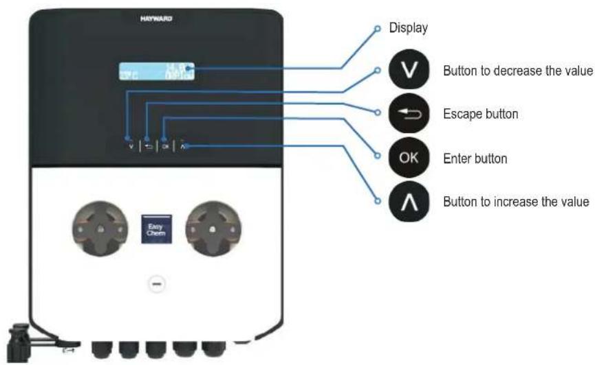
6a. Description of the home screen and defaults parameters
Default parameters
| n Item Value | |
| 1 Language EN | |
| 2 Set Point value 7.4 pH | 700 mV | |
| 3 Dosing method Acid (pH) Low (Redox) | |
| 4 OFA Time OFF | |
| 5 Calibration Full | |
| 6 Circulation pump ON | |
| 7 Dosing type PROP; Relay Aux1, Aux2, Aux3 are disabled | |
| 8 IN Freq. | OFF |
| 9 Flow Input NO (normally open) (Reed Sensor) |
| 10 Power ON Delay | OFF |
| 11 Flow Delay | OFF |
Measure alarm ranges default parameters
| n | Item | Limits |
| 1 | Temp. Measure min | + 10°C |
| 2 | Temp. Measure Max | + 38°C |
| 3 | pH Measure min | 6 pH |
| 4 | pH Measure Max | 8.0 pH |
| 5 | ORP Measure min | +450 mV |
| 6 | ORP Measure Max | +850 mV |
To restore the default parameters, follow the steps below:
• Power off the device unit
- Keep V and ∧ pressed and power on the unit
• The unit will display Init.default
- Select the unit to reset - WiFi module or dosing system
- Press V or A to select Yes or no
- Select Yes and press OK to restore the default parameters.
6b. Main menu
Press OK 3 seconds to run the main menu and then use and select one of the following functions:
6b1. Calibration 6b2. Setup

flowchart
graph LR
    A["Main Menu CALIBRATION"] --> B["Main Menu SETUP"]
    B --> C["Main Menu ADVANCED"]
    C --> D["Main Menu PRIMING"]
6b3. Advanced 6b4. Priming
Main menu - Press OK 3 seconds.
At the entry of each menu item, the parameter can be directly modified by using ∧ and ∨.
Confirmation of the current setting and switching to the next item is done by pressing the OK button.
The menu has a circular structure: once you arrive at last item, the confirmation of the parameter set by pressing determines the return to the first menu item.

The Calibration menu consists of three (3) sub-menus:
• pH: Calibration routine
- ORP: Calibration routine
• Temperature: Calibration routine
Note: please check sections 6f, 6g and 6h for step by step calibration routine.
Main Menu
CALIBRATION
CALIBRATION
PH
CALIBRATION ORP
CALIBRATION
TEMPERATURE
The Setup menu consists of two (2) sub-menus:
• pH
- ORP
Scroll through the menu using a single item and confirm with .

Main Menu
SETUP
SETUP PH
SETUP ORP

HAYWARD®
Setup pH
The Setup pH menu consists of six (6) sub-menus:
- Setpoint pH: 7.4pH (range 6-8pH) Set the pH value keep in the pool.
- Setpoint Type: Acid (Acid/Alkaline) Type dosing product to regulate the pH value. Acid: add chemical Acid product, Alka: add chemical Alkaline product.
- Temperature: 25°C (Automatic compensation by manual value or set Automatic to use an external temperature sensor)
- OFA Alarm: Over Feed alarm value in minutes value (OFF...60'), it is a maximum relay time activation.
- Alarm Min: Setting the minimum pH alarm value (0,0...6,0 pH)
• Alarm Max: Setting the Maximum pH alarm value (8,0...14,0 pH)
• *Time ON: range from 5" to 360" (Default Time ON: 180")
• *Time OFF: range from 5" to 360" (Default Time OFF: 360")
\*Notes:
The items Time ON and Time OFF will be displayed if the Timed dosing method is set in the Advanced menu.
Time OFF must be equal to or greater than Time ON.
Scroll through the menu using

select the item and confirm with

Setup ORP
The Setup ORP menu consists of five (5) sub-menus:
- Setpoint ORP: 700mV (range 400-850mV) Set the ORP value keep in the pool.
- Setpoint Type: Low (LOW/HIGH) Type of dosing regulation. Low: add chemical chlorine, High: reduce chemical chlorine.
- OFA Alarm: Over Feed alarm value in minutes value (OFF...60'), it is a maximum relay time activation.
- Alarm Min: Setting the minimum ORP alarm value (0...600 mV)
• Alarm Max: Setting the Maximum ORP alarm value (800...1000 mV)
• *Time ON: range from 5" to 360" (Default Time ON: 180")
• *Time OFF: range from 5" to 360" (Default Time OFF: 360")
\*Notes:
The items Time ON and Time OFF will be displayed if the Timed dosing method is set in the Advanced menu.
Time OFF must be equal to or greater than Time ON.
SETUP PH
SETPOINT PH
7.4pH
SETPOINT TYPE ACID (pH-)
TEMPERATURE
25°C
OFA ALARM
OFF
ALARM MIN
6.0pH
ALARM MAX
8.0pH
TIME ON 180"
TIME OFF
360"
SETUP ORP
SETPOINT ORP
700mV
SETPOINT TYPE
LOW
OFA ALARM
OFF
Scroll through the menu using your item and confirm with .


The Advanced menu consists of the following sub-menus:
• Language: Set language menu (EN, IT, ES, DE, FR)
- Circulating Pump: Enable/Disable input signal from pool circulation pump High voltage 230Vac.
- In Freq.: Flow rate function measure, Enable/Disable input frequency signal from water meter pulse sender, set Pulse/Liter or Liter/Pulse.
- Calib. pH: Double ore Single point and Reference calibration, Double point 7pH and 4pH, Single point 7pH, reference pH value.
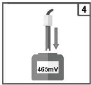
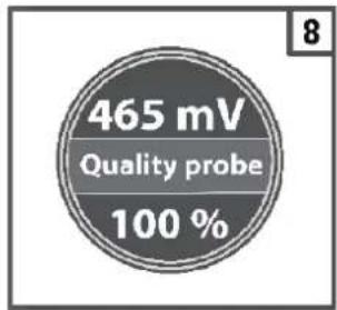
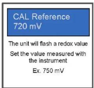
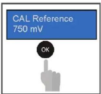
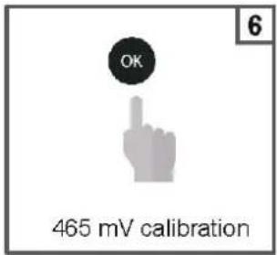
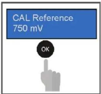
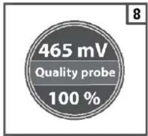
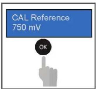
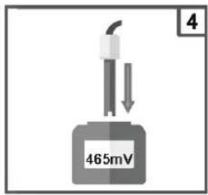
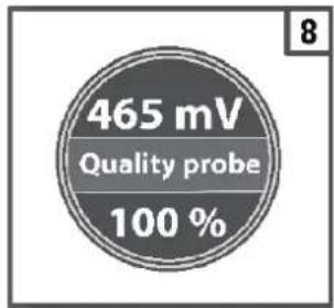
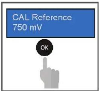
- Calib. ORP: Single point and Reference calibration, Single point 465 mV, reference ORP mV value.
- Calib. Temp: Reference calibration by external hand held controller.
- Dosing Type pH: Proportional, Timed, On/Off, Off (disable pump)
- Dosing Type ORP: Proportional, Timed, On/Off, Off (disable pump)
- Aux Relay: Set AUX1: pH or disable; AUX2: ORP or Disable
- Password: Set value to enable password of setting menu. (0000 disable)
- Reset Cal: Menu to reset the last Calibration value, and reload the factory settings
- Reset all Param.: Menu to reset all parameter and reload the factory settings
- Control Panel: Menu to show the input raw signal, pH in mV raw signal, ORP in mV raw signal, Temperature in Ohm raw signal.
- Reed: set logic sensor NO/ NC (normally open/close)
- P.On Delay: Power ON delay function is a countdown timer Off...60' to delay dosing actions when switch on the device. During this period the system wait the chemical measure stabilizing the dosing pump are disable.
- Flow Delay: Flow delay function is a countdown timer Off...60' to delay dosing actions when the flow rate will be restable, and during this time the chemical measure will be stabilizing the dosing pump are disable.
ALARM MIN
600mV
ALARM MAX
800mV
TIME ON 180"
TIME OFF
360"
Main Menu
ADVANCED
ADVANCED MENU
LANGUAGE
Scroll through the menu using your home item and confirm with .

To exit the menu, press the instrument will display the question "save?";
confi rm with OK
For not saving, select NO using a confirm with .

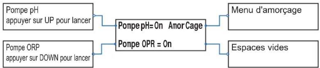
Priming menu dosing pumps, please select the dosing pump to start the priming action.
Main Menu PRIMING
pH:Off ORP:Off
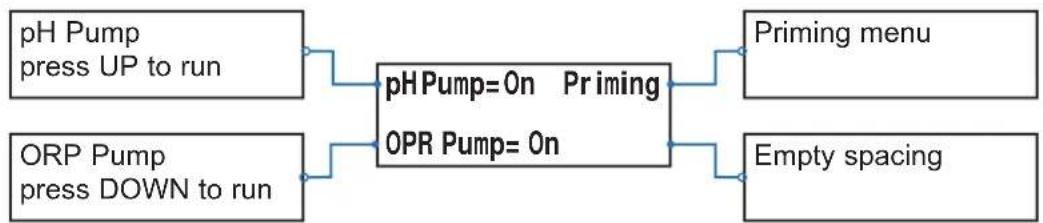
flowchart
graph LR
    A["pH Pump press UP to run"] --> C["pHPump=0n Priming"]
    B["ORP Pump press DOWN to run"] --> C
    C --> D["OPR Pump=0n"]
    E["Priming menu"] --> C
    F["Empty spacing"] --> C
6c. View Parameters
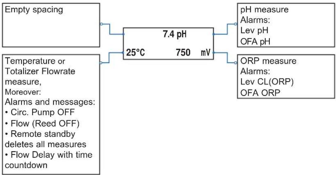
flowchart
graph LR
    A["Empty spacing"] --> B["7.4 pH"]
    C["Temperature or Totalizer Flowrate measure, Moreover: <br>    • Circ. Pump OFF<br>    • Flow (Reed OFF)<br>    • Remote standby deletes all measures<br>    • Flow Delay with time countdown"] --> B
    B --> D["pH measure<br>    <br>    • <br>    • pH<br>    • OFA pH"]
    B --> E["ORP measure<br>    <br>    • <br>    • OFA ORP"]
6d. Standby system
Press (V) (e.g., us) the system sets in StandBy mode; all functions are disabled
6e. Reset OFA Timer
Press OK (seconds) to reset OFA Alarm or press to reset OFA Alarm.
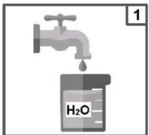
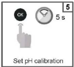
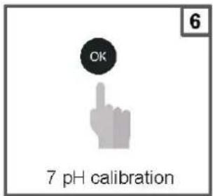
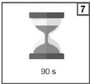
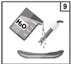
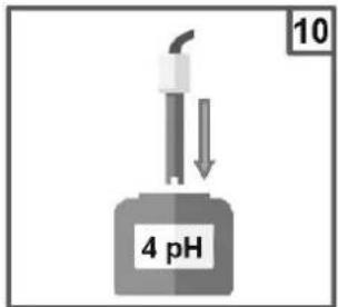
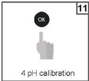
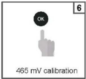
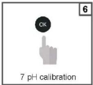
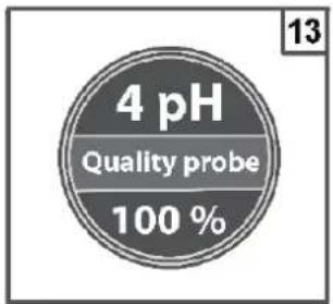
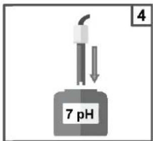
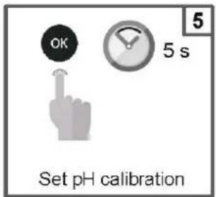
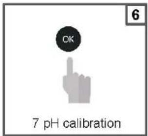
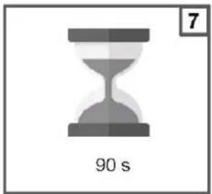
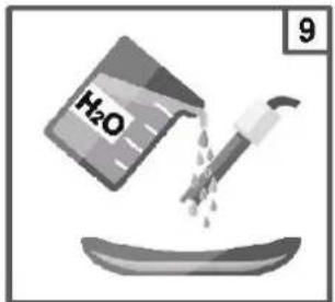
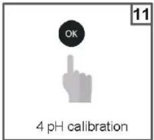
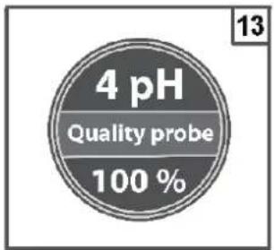
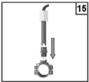
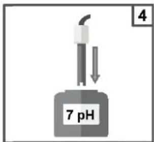
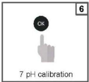
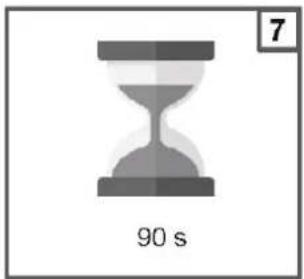
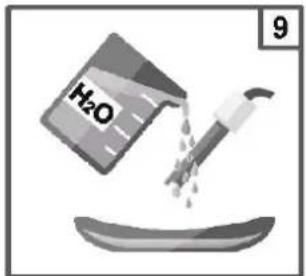
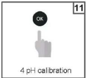
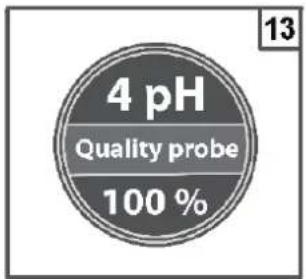
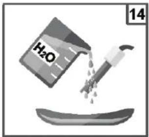
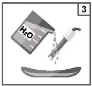
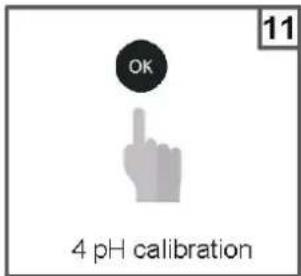
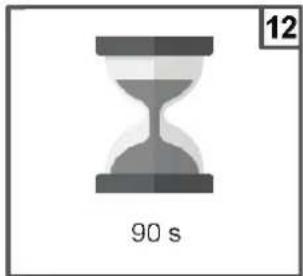
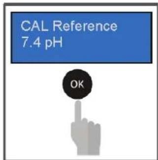
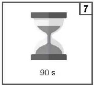
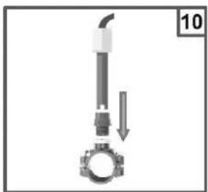
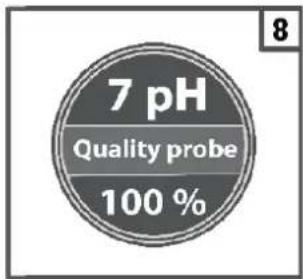
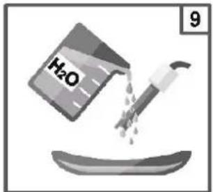
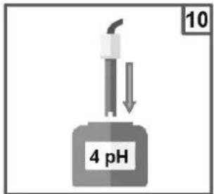
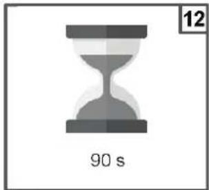
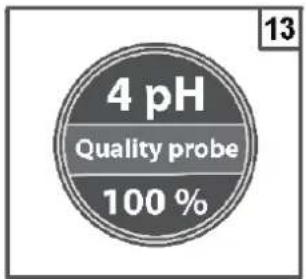
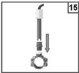
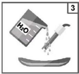
6f. pH probe calibration
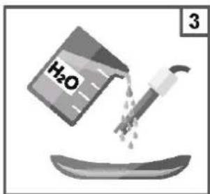
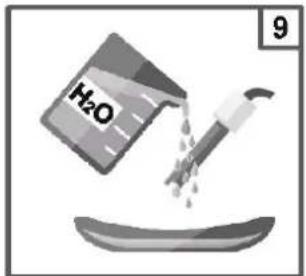
Always begin the calibration procedure with a calibration reset.
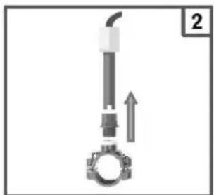
natural_image
Mechanical component diagram showing a piston and crankshaft assembly with an upward arrow (no text or symbols)


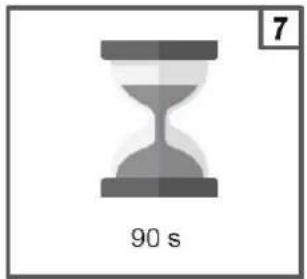
natural_image
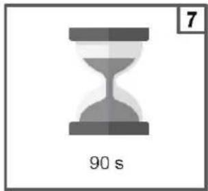
Gray hourglass icon with '90 s' label and number 7 in top-right corner (no other text or symbols)


natural_image
Mechanical assembly diagram showing a valve and bolt with a downward arrow indicating motion (no text or symbols)

Note: If you have selected the "1 point cal.", the calibration will be made only in 1 point using the 7pH buffer solution.
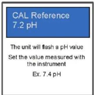
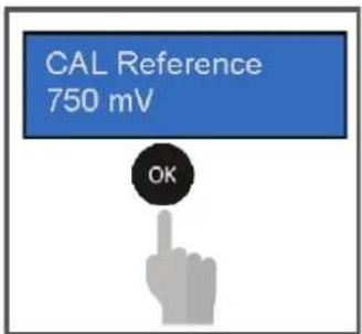
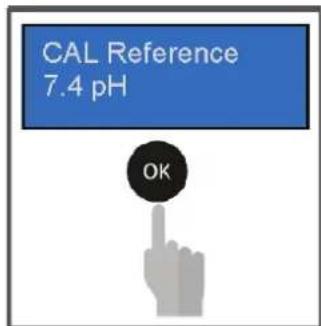
Reference calibration

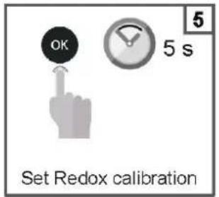
6g. ORP probe calibration
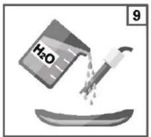
Always begin the calibration procedure with a calibration reset.
natural_image
Mechanical component diagram showing a shaft and gear assembly with an upward arrow (no text or symbols)


natural_image
Mechanical assembly diagram showing a pipe inserted into a gear with a downward arrow indicating motion (no text or symbols)

Reference calibration
6h. Temperature probe calibration
Always begin the calibration procedure with a calibration reset.
CAL Reference 26°C
The unit will flash a temperature value
Set the temperature value measured with the instrument Ex. 27°C
CAL Reference 27°C

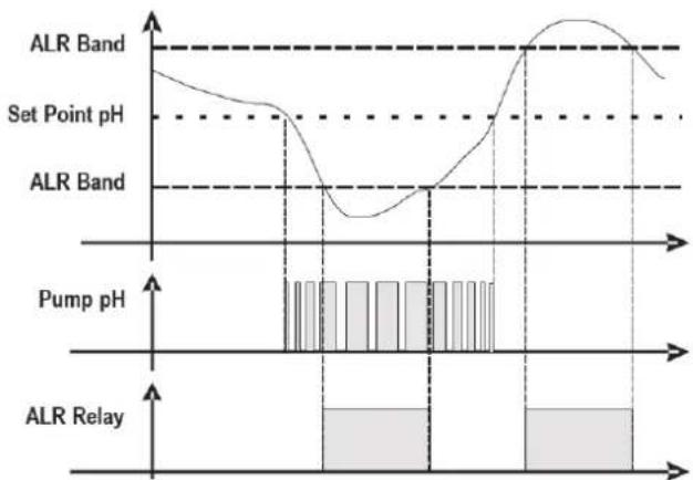
7. DOSING METHOD
Setpoint = 7.4 pH
Dosing mode = Acid
Prop. Band= 1.0 pH (* Fixed value)

line
| Input pH measure | Dosing period 10 minutes |
| ---------------- | ------------------------ |
| 7.2 | 30% |
| 7.48 | 30% |
| 8.6 | 95% |
Setpoint = 700 mV
Dosing mode = Low
Prop. Band= 250mV (* Fixed value)

line
| Input ORP measure | Dosing period 10 minutes |
| ----------------- | ------------------------ |
| 400 | 95% |
| 750 | 95% |
| >750 | 30% |
Alarm for the pH/ORP Set Point
When the alarm band is set, a work window is created. If the allowed limits are exceeded the alarm relay closes
and remains closed until the measurement is reset or OK pressed to deactivate the alarm.
When the OFA time (Over Feed Alarm) is set, the dosing time of Set Point pH/ORP in time is controlled with two alarms:
- First alarm at 70% of the time set is seen on the display, the alarm relay closes.
- Second alarm at 100% of the time set is seen on the display and the alarm relay closes and the pH/ORP pump is blocked.

seconds) to reset OFA Alarm or press

o reset OFA Alarm.
line
| Parameter | Value |
| --------------- | ----- |
| ALR Band | High |
| Set Point pH | Medium|
| ALR Band | Low |
| Pump pH | Low |
| ALR Relay | High |
(*1 Measure Alarm Ranges - fixed values)
| n Item Limits | |
| 1 Temp. Measure min + 10°C |
| 2 Temp. Measure Max + 38°C |
8. ALARMS
| Alarm Display Actions to do | | |
| Level*only active measures | Lev Low | - Restore Product tank |
| Out of Range measure | ALARM BAND | - Replace or check the measure probe- Restore measure |
| OFA First Alarm(time >70%) | OFA_1 blinking |  - Press 3 seconds to reset or press for seconds to reset - Press 3 seconds to reset or press for seconds to reset   |
| OFA Second Alarm(time 100%) | OFA_2 |  - Press 3 seconds to reset or press for seconds to reset - Press 3 seconds to reset or press for seconds to reset   |
| Flow Rate | Flow | - Restore Flow Rate |
| Calibration Function | CALIBRATION ERR | - Restore Probe or Buff er solution and repeat calibration procedure |
| System Error | Parameter S error | OK- Press Restore Default parameter- Broken Unit |
| Alarm measure (*1) | High Measure Low Measure | - Adjust the chemical concentration |
(*1 Measure alarm ranges default parameters)
| n Item Limits | |
| 1 Temp. Measure min + 10°C |
| 2 Temp. Measure Max + 38°C |
| 3 pH Measure min 6 pH | |
| 4 pH Measure Max 8.0 pH |
| 5 ORP Measure min +450 mV |
| 6 ORP Measure Max +850 mV |
9. SERVICING
During the first 10-15 days, your system will require more attention:
- Check that the pH remains at the ideal level (7.2 to 7.4).
- If the pH is exceptionally unstable and uses a lot of acid, check the alkalinity (see table).
If the balance is highly unstable, contact your pool installer/builder.
REMEMBER that the system needs a certain amount of time to adapt to your pool and will require additional chemicals during the first 3-5 days.
The pool must be regularly maintained and the skimmer baskets emptied whenever necessary.
Also check that your filter is not clogged.
DOSING PUMPS: Regularly check the acid level to ensure that the pump does not run dry. The dosing pump must be checked and serviced at regular intervals. The Santoprene tube of the peristaltic pump has a lifetime of 2 years. We recommend that you change it once a year.
Servicing the probe
The probe must be clean and free from oil, chemical deposits and contamination to function properly. As it is in continuous contact with the water in the pool, the probe may need to be cleaned weekly or monthly, depending on the number of bathers and other specific pool characteristics. A slow response, more frequent pH calibration and inconsistent readings indicate that the probe needs to be cleaned.
To clean the probe, turn off the power to the EasyChemDouble.
Unplug the probe connector from the control box, unscrew the probe and carefully remove it from the chamber. Clean the probe bulb with a soft toothbrush and regular toothpaste.
A household washing-up liquid detergent may also be used to remove any oil.
Rinse with fresh water, replace the Teflon tape on the threads, and reinstall the probe.
If the probe continues to give inconsistent readings or requires excessive calibration after it has been cleaned, it should be replaced. The lifetime of the probes is 1 year. We recommend that you calibrate them every month during the season the pool is in use.
Wintering
The EasyChemDouble, probe and pool piping run the risk of being damaged if the water freezes. In regions that experience long periods of cold weather, be sure to drain all the water from the pump and filter and from the supply and return pipes before winter. Do not remove the control box.
Probe storage
The end of the probe must always be in contact with water or a solution of KCl. If it is removed from the measuring chamber, it should be stored in the plastic cap provided (filled with water). If the storage cap has been mislaid, the probe should be stored separately in a small glass or plastic container with its end immersed in water.
The probe must always be in a frost-free environment.
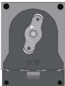
Hose replacement procedure (valid for 2 and 3 rollers)
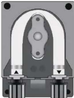
natural_image
Cross-sectional diagram of a mechanical component with symmetrical arch and base (no text or symbols)
Open the pump's lid and release the hose by pulling the left connector upward.
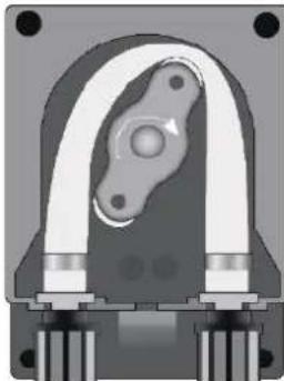
natural_image
Cross-sectional view of a mechanical component with no visible text or symbols
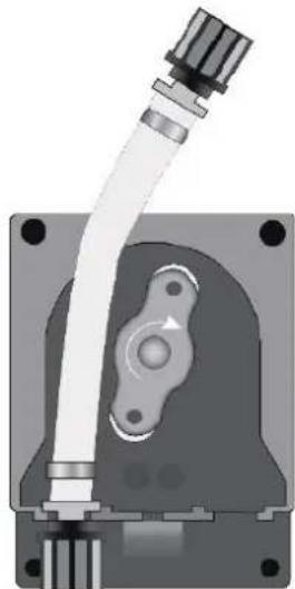
Position the roller at 7h05, turning it in the direction of the circular arrow.
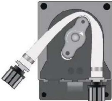
natural_image
Mechanical component diagram showing a housing with attached cable and mounting base (no text or symbols)
Completely release the left connector, holding it taut towards the outside, and turn the roller in the direction of the circular arrow so that the hose is freed up to the right connector.
natural_image
3D rendered mechanical component with central bore and mounting base (no text or symbols)
Position the roller at 7h05, turning it in the direction of the circular arrow.
natural_image
Mechanical component diagram showing a pipe fitting and housing (no text or symbols)
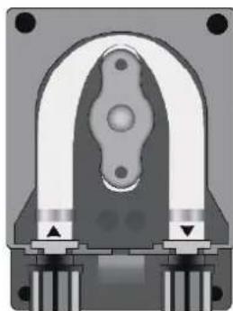
Insert the left connector into the relative housing and pass the hose under the roller's guide. Turn the roller in the direction of the circular arrow, simultaneously accompanying the hose into the pump's head, until the right connector is reached.
natural_image
Cross-sectional diagram of a mechanical component with no visible text or symbols
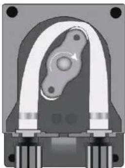
Close the pump's lid and press its surface hard so that it is properly locked into place.
Storing the pump after use
natural_image
Cross-sectional view of a mechanical component with no visible text or symbols
When the regulation device must be stored, clean water should be pumped through the hose in order to rinse it.
Then position the roller at 7h05, turning in the direction indicated by the circular arrow.
These two precautions will facilitate the subsequent reactivation of the unit.
10. TROUBLESHOOTING GUIDE
No display
Check that the On / Off switch is on.
Check the connection cable between the display and the control box.
Check the power supply: 210-230 V\~ 50 Hz.
Check the dosing method if the OFA Alarm show continuously.
Chech the lifetime probe by calibration method.
Chech the running pump by Priming function.
If the problem persists, contact your pool installer/builder.
Provision regarding professional waste from electrical and electronic equipment (WEEE). In compliance with directive 2012/19/EU regarding the management of waste from electrical and electronic equipment, this pump must be disposed of at a waste sorting site.
==> for more information contact your dealer.
Good management of waste from electrical and electronic equipment contributes to the prevention of damage to the environment and human health.
LIMITED WARRANTY
All HAYWARD products are covered for manufacturing defects or material defects for a warranty period of 3 years as of date of purchases. Any warranty claim should be accompanied by evidence of purchase, indicating date of purchase. We would therefore advise you to keep your invoice.
The HAYWARD warranty is limited to repair or replacement, as chosen by HAYWARD, of the faulty products, provided that they have been subjected to normal use, in compliance with the guidelines given in their user guides, provided that the products have not been altered in any way, and provided that they have been used exclusively with HAYWARD parts and components. The warranty does not cover damage due to frost and to chemicals. Any other costs (transport, labour, etc.) are excluded from the warranty.
HAYWARD may not be held liable for any direct or indirect damage resulting from incorrect installation, incorrect connection, or incorrect operation of a product.
In order to claim on a warranty and in order to request repair or replacement of an article, please ask your dealer.
No equipment returned to our factory will be accepted without our prior written approval.
Wearing parts are not covered by the warranty.
The wearing parts of the salt water chlorinator listed below must be maintained according to their estimated service life:
Seal set = 2 years
Santoprene tube = 2 years
Roller = 2 years

natural_image
Abstract geometric logo with stylized letter H inside a circular frame (no text or symbols)
HAYWARD®
natural_image
Two black electronic devices with control buttons and indicator lights, no visible text or symbols on the devices themselves.
CE EAC UK CA

natural_image
Two line icons: one open with an information symbol, the other closed with an open book (no text or symbols present)
EasyChem Double and Plug Version | pH - ORP
BETRIEBSANLEITUNG
BITTE BEWAHREN SIE DIESES HANDBUCH ZUM SPÄTEREN NACHSCHLAGEN AUF.
natural_image
Diagram showing a mechanical assembly process with three stages: brick wall, vertical support, and final view (no text or symbols)
natural_image
Exterior view of a modern industrial air purifier unit with dual fans and control panel (no visible text or symbols)

natural_image
Close-up of a black industrial device with two metallic components and a digital display, showing a red arrow labeled 't' pointing to a component (no text or symbols on the device itself)

natural_image
Interior view of a black industrial machine with internal components and a red arrow indicating rotation (no visible text or symbols)
Anschluss des
Etiketts:
natural_image
Diagram of a cable being inserted into a device, showing cable routing and wire movement (no text or symbols)
STROMVERSORGUNGSKABEL
natural_image
Diagram of a mechanical device with a curved cable and labeled component (no text or symbols)
natural_image
Simple line drawing of a cable with a box and ring, no text or symbols present
WICKELN SIE DAS KABEL FÜR EINE
UMDREHUNG
natural_image
Front view of a black electronic device casing with mounting holes and internal circuitry (no visible text or symbols)
natural_image
Silhouette of two people standing in front of a dark rectangular object (no text or symbols visible)

natural_image
Front view of a black industrial electrical control unit with two circular components and a digital display (no visible text or symbols)
natural_image
Mechanical component diagram showing a shaft and gear assembly with an upward arrow (no text or symbols)


natural_image
Mechanical assembly diagram showing a bolt and pipe assembly with a downward arrow indicating motion (no text or symbols)


natural_image
Mechanical component diagram showing a shaft and gear assembly with an upward arrow (no text or symbols)


natural_image
Mechanical component diagram showing a lever and gear assembly (no text or symbols)


The unit will flash a temperature value
Set the temperature value measured with the instrument Ex. 27°C
CAL Reference 27°C

7. DOSIERVERFAHREN
Sollwert = 7.4 pH
Dosiermodus = Säure
Prop. Band= 1,0 pH (* fester Wert)
Sollwert = 700 mV
natural_image
Cross-sectional view of a mechanical component with symmetrical arms and mounting holes (no text or symbols visible)
natural_image
Cross-sectional view of a mechanical component with no visible text or symbols
natural_image
Mechanical component diagram showing a housing with a cable and housing assembly (no text or symbols visible)
natural_image
3D rendered mechanical component with central bore and mounting base (no text or symbols)
natural_image
Mechanical assembly diagram showing a pipe fitting and housing component (no text or symbols)
natural_image
Cross-sectional diagram of a mechanical component with symmetrical U-shaped housing and mounting points (no text or symbols)
natural_image
Mechanical component diagram showing a curved housing with internal components and mounting holes (no text or symbols)
natural_image
Abstract geometric logo with stylized letter H inside a dark circular frame (no text or symbols)
HAYWARD®

natural_image
Two black rectangular electronic devices with control buttons and indicator lights, no visible text or symbols on the surfaces.
CE EAC UK CA

natural_image
Two line icons: one open with an information symbol, the other closed with an open book (no text or symbols present)
natural_image
Diagram showing four sequential steps of a mechanical or structural assembly on a brick wall, with no visible text or symbols.

natural_image
Exterior view of a modern industrial air purifier unit with dual fans and control panel (no visible text or symbols)
natural_image
Close-up of a black industrial device with attached components and a red arrow indicating rotation (no text or symbols visible)

natural_image
Interior view of a black industrial machine with internal components and a red arrow indicating rotation (no text or symbols visible)
natural_image
Diagram of a cable being inserted into a device, showing cable routing and cable attachment (no text or symbols)
natural_image
Simple line drawing of a cable being inserted into a device, no text or symbols present
natural_image
Simple line drawing of a cable with a box and loop, no text or symbols present
ENVUELVA EL CABLE UNA VUELTA
natural_image
Front view of a black electronic device casing with mounting holes and internal circuitry (no visible text or symbols)
natural_image
Exterior view of a modern office building (no signage)
natural_image
Front view of a black industrial water heater unit with dual circular components and a digital display (no visible text or symbols)

Menú principal
SETUP

SETUP pH
SETUP ORP

HAYWARD®
Setup pH
Menú principal
AVANZADO
natural_image
Mechanical component diagram showing a shaft and gear assembly with an upward arrow (no text or symbols)


natural_image
Mechanical assembly diagram showing a valve and gasket with a downward arrow indicating motion (no text or symbols)


natural_image
Mechanical component diagram showing a shaft and gear assembly with an upward arrow (no text or symbols)


natural_image
Mechanical assembly diagram showing a pipe inserted into a gear with a downward arrow indicating motion (no text or symbols)

The unit will flash a temperature value
Set the temperature value measured with the instrument Ex. 27°C
CAL Reference 27°C

natural_image
Cross-sectional diagram of a mechanical component with symmetrical supports and central hub (no text or symbols)
natural_image
Cross-sectional view of a mechanical component with no visible text or symbols
natural_image
Mechanical component diagram showing a housing with attached cable and mounting base (no text or symbols)
natural_image
3D rendered mechanical component with central bore and mounting base (no text or symbols)
natural_image
Mechanical component diagram showing a shaft and housing assembly (no text or symbols)
natural_image
Cross-sectional diagram of a mechanical component with symmetrical U-shaped housing and mounting base (no text or symbols)
natural_image
Cross-sectional view of a mechanical component with no visible text or symbols
natural_image
Abstract geometric logo with stylized letter H inside a circular frame (no text or symbols)
HAYWARD®
CE EAC UK CA

natural_image
Two line icons: one open with an information symbol, the other closed with an open book (no text or symbols present)
EasyChem Double and Plug version | pH · ORP
MANUEL DU PROPRIÉTAIRE
VEUILLEZ CONSERVER CE MANUEL POUR TOUTE RÉFÉRENCE ULTÉRIEURE


L'ÉQUIPEMENT EST DESTINÉ À ÊTRE UTILISÉ UNIQUEMENT DANS LES PISCINES
3b. Installation murale
natural_image
Diagram showing four sequential steps of a mechanical or structural assembly on a brick wall, with no visible text or symbols.


HAYWARD®
natural_image
Exterior view of a modern industrial air purifier unit with dual fans and control panel (no visible text or symbols)
natural_image
Close-up of a black industrial device with attached components and a red arrow indicating rotation (no text or symbols)
natural_image
Interior view of a black industrial machine with internal components and a red arrow indicating rotation (no visible text or symbols)
natural_image
Diagram of a mechanical assembly with a lever and conveyor belt, no text or symbols present
CÂBLE D'ALIMENTATION
③

natural_image
Simple line drawing of a mechanical device with a curved arrow indicating motion (no text or symbols)
④
ENROULER LE CÂBLE POUR UN TOUR
natural_image
Front view of a black electronic device casing with mounting holes and internal circuitry (no visible text or symbols)
natural_image
Silhouette of two people standing in front of a dark rectangular object (no text or symbols visible)

natural_image
Front view of a black industrial electrical control unit with two circular buttons and a digital display (no visible text or symbols)


HAYWARD®
6. CONFIGURATION ET FONCTIONNEMENT
flowchart
graph LR
    A["Menu principal ÉTALONNAGE"] --> B["Menu principal SETUP"]
    B --> C["Menu principal ADVANCED (AVANCÉ)"]
    C --> D["Menu principal AMORÇAGE"]
Menu principal
SETUP
SETUP PH
SETUP ORP

HAYWARD®
Configuration pH
Menu principal
AMORÇAGE
pH:Off ORP:Off
natural_image
Mechanical component diagram showing a shaft and gear assembly with an upward arrow (no text or symbols)


natural_image
Mechanical component diagram showing a valve assembly with a bolt and pipe, no text or symbols present


natural_image
Mechanical component diagram showing a shaft and gear assembly with an upward arrow (no text or symbols)


natural_image
Mechanical assembly diagram showing a pipe inserted into a gear with a downward arrow indicating motion (no text or symbols)

The unit will flash a temperature value
Set the temperature value measured with the instrument Ex. 27°C
CAL Reference 27°C

7. MÉTHODE DE DOSAGE
Point de consigne = 7,4 pH
Mode de dosage = Acide
natural_image
Cross-sectional diagram of a mechanical component with symmetrical arms and mounting holes (no text or symbols)
natural_image
Cross-sectional view of a mechanical component with no visible text or symbols
natural_image
Mechanical component diagram showing a housing with a curved pipe and mounting base (no text or symbols)
natural_image
3D rendered mechanical component with central bore and mounting base (no text or symbols)
natural_image
Mechanical assembly diagram showing a connector with tubing and housing (no text or symbols)
natural_image
Cross-sectional diagram of a mechanical component with symmetrical U-shaped housing and mounting base (no text or symbols)
natural_image
Cross-sectional diagram of a mechanical component with no visible text or symbols
natural_image
Abstract geometric logo with stylized letter H inside a circular frame (no text or symbols)
HAYWARD®

natural_image
Two black rectangular electronic devices with control buttons and indicator lights, no visible text or symbols on the surfaces.
CE EAC UK CA

natural_image
Two line icons: one open with an information symbol, the other closed with an open book (no text or symbols present)
EasyChem Double e Plug | pH · ORP
MANUALE D'USO
natural_image
Diagram showing four sequential steps of a mechanical or structural assembly on a brick wall, with no visible text or symbols.
natural_image
Exterior view of a modern industrial air purifier unit with dual fans and control panel (no visible text or symbols)
natural_image
Close-up of a black industrial device with attached components and a red arrow indicating rotation (no text or symbols visible)

natural_image
Interior view of a black industrial machine with internal components and a red arrow indicating rotation (no visible text or symbols)
natural_image
Simple line drawing of a mechanical device with a lever and cable, no text or symbols present
natural_image
Simple line drawing of a mechanical device with a curved arrow indicating motion (no text or symbols)
④

AVVOLGERE IL CAVO DI UN GIRO
natural_image
Front view of a black electronic device casing with mounting holes and internal circuitry (no visible text or symbols)
natural_image
Exterior view of a modern office building (no signage)

natural_image
Front view of a black industrial electrical control unit with two circular components and a digital display (no visible text or symbols)


HAYWARD®
6. IMPOSTAZIONE E FUNZIONAMENTO
TEMPO DI ACCENSIONE 180"
TEMPO DI ACCENSIONE 180"
natural_image
Mechanical component diagram showing a piston and crankshaft assembly with an upward arrow (no text or symbols)


natural_image
Mechanical assembly diagram showing a valve and gasket with a downward arrow indicating motion (no text or symbols)

natural_image
Mechanical component diagram showing a shaft and gear assembly with an upward arrow (no text or symbols)


natural_image
Mechanical assembly diagram showing a pipe with a valve and a gear base, no text or symbols present

The unit will flash a temperature value
Set the temperature value measured with the instrument Ex. 27°C
CAL Reference 27°C

7. METODO DI DOSAGGIO
Setpoint= 7,4 pH
line
| pH Level | Banda ALR |
| -------------- | --------- |
| Setpoint pH | 0 |
| Banda ALR | 0 |
| Pompa pH | 0 |
| Banda ALR | 0 |
natural_image
Cross-sectional view of a mechanical component with symmetrical U-shaped housing and mounting holes (no text or symbols)
natural_image
Cross-sectional view of a mechanical component with no visible text or symbols
natural_image
Mechanical component diagram showing a housing with a cable and housing assembly (no text or symbols visible)
natural_image
3D rendered mechanical component with central bore and mounting base (no text or symbols)
natural_image
Mechanical component diagram showing a pipe fitting and housing (no text or symbols)
natural_image
Cross-sectional diagram of a mechanical component with symmetrical U-shaped housing and mounting base (no text or symbols)
natural_image
Cross-sectional diagram of a mechanical component with no visible text or symbols
natural_image
Abstract geometric logo with stylized letter H inside a circular frame (no text or symbols)
HAYWARD®
natural_image
Two black rectangular electronic devices with control buttons and indicator lights, no visible text or symbols on the surfaces.
CE EAC UK CA

natural_image
Two line icons: one open with an information symbol, the other closed with an open book (no text or symbols present)
natural_image
Diagram showing four sequential steps of a mechanical or structural assembly on a brick wall, with no visible text or symbols.
natural_image
Exterior view of a modern industrial air purifier unit with dual fans and control panel (no visible text or symbols)

natural_image
Close-up of a black industrial device with attached components and a red arrow indicating rotation (no text or symbols visible)

natural_image
Interior view of a digital water dispenser with black casing and control panel, showing internal components and a red arrow indicating rotation (no text or symbols visible)
natural_image
Diagram of a mechanical assembly with numbered label (2) and directional arrow, no readable text or symbols present.
CABO DE ALIMENTAÇÃO
③
natural_image
Simple line drawing of a mechanical device with a curved arrow indicating motion (no text or symbols)
④

ENROLAR O CABO COM UMA VOLTA
natural_image
Front view of a black electronic device casing with mounting holes and internal circuitry (no visible text or symbols)
natural_image
Silhouette of a person standing in front of a dark rectangular object with a horizontal line above (no text or symbols visible)

natural_image
Front view of a black industrial electrical control unit with two circular components and a digital display (no visible text or symbols)


HAYWARD®
flowchart
graph LR
    A["Menu principal AVANÇADO"] --> B["Menu principal PRIMING [ESCORVAMENTO"]]


natural_image
Mechanical component diagram showing a piston and crankshaft assembly (no text or symbols)


natural_image
Mechanical assembly diagram showing a valve and gasket with a downward arrow indicating motion (no text or symbols)

natural_image
Mechanical component diagram showing a valve and gasket assembly (no text or symbols)


natural_image
Mechanical component diagram showing a lever and gear assembly (no text or symbols)

The unit will flash a temperature value
Set the temperature value measured with the instrument Ex. 27°C
CAL Reference 27°C

7. MÉTODO DE DOSAGEM
Setpoint = 7.4 pH
natural_image
Cross-sectional view of a mechanical clamp or bracket component (no visible text or symbols)
natural_image
Cross-sectional view of a mechanical component with no visible text or symbols
natural_image
Mechanical component diagram showing a housing with attached cable and mounting holes (no text or symbols)
natural_image
3D rendered mechanical component with central bore and mounting base (no text or symbols)
natural_image
Mechanical component diagram showing a shaft and housing assembly with no visible text or symbols
natural_image
Mechanical component diagram showing a U-shaped housing with mounting feet and central bore (no text or symbols)
natural_image
Cross-sectional view of a mechanical component with no visible text or symbols