RS-4 - Riflescope MINOX - Free user manual and instructions
Find the device manual for free RS-4 MINOX in PDF.


| Product Type | Riflescope for hunting and sport shooting |
| Brand | Minox |
| Model | RS-4 |
| Magnifications | 1-4x, 2.5-10x, 3-12x depending on variant |
| Objective Diameter | 24, 42, 50 or 56 mm depending on variant |
| Reticle | Illuminated, second focal plane, 10 brightness levels |
| Power Supply | CR 2032 battery (included, integrated) |
| Diopter Compensation | -3 to +2 dpt |
| Elevation/Windage Adjustment | 1 cm / 100 m per click, range ±200 cm / 100 m |
| Parallax Correction | Adjustable from 10 m to infinity (except 1-4x24: fixed at 100 m) |
| Tube Diameter | 30 mm |
| Gas Filling | Nitrogen, fog-proof |
| Waterproofness | 4 m depth for 30 min |
| Weight | From 470 g to 755 g depending on variant |
| Length | From 274 mm to 365 mm depending on variant |
| Warranty | 2 years legal + 10 years extension on mechanical and optical |
| Included Accessories | Lens caps, Allen key, cleaning cloth, CR 2032 battery |
Frequently Asked Questions - RS-4 MINOX
User questions about RS-4 MINOX
0 question about this device. Answer the ones you know or ask your own.
Ask a new question about this device
Download the instructions for your Riflescope in PDF format for free! Find your manual RS-4 - MINOX and take your electronic device back in hand. On this page are published all the documents necessary for the use of your device. RS-4 by MINOX.
USER MANUAL RS-4 MINOX
natural_image
Black MUNOX optical lens with red background (no text or symbols on body)BEDIENUNGSANLEITUNG | INSTRUCTION MANUAL | MODE D'EMPLOI MANUAL DE INSTRUCCIONES | ISTRUZIONI D'USO | HASZNÁLATI ÚTMUTATÓ | INSTRUKCJA OBSŁUGI | РУКОВОДСТВО ПО ЭКСПЛУАТАЦИИ
MINOX RS-4
1-4x24 | 2.5-10x42 | 2.5-10x50 (S) | 3-12x56 (BDC)
ZIELFERNROHR | RIFLESCOPE | LUNETTE DE VISÉE | VISOR | CANNOCCHIALE DI
PUNTAMENT | CÉLZÓTÁVCSŐ | CELOWNIK OPTYCZNY | ОПТИЧЕСКИЙ ПРИЦЕЛ
WILLKOMMEN BEI MINOX
Abmessungen in mm....21
ABMESSUNGEN IN MM
1-4x24 2.5-10x42 2.5-10x50 (S) 3-12x56 (BDC)
A 274 295 344 365
D 54,5 62,0 62,0 62,0
E 96,8 97,0 97,0 97,0
F 30,0 48,0 56,0 62,0
G 45,4 45,4 45,4 45,4
N 46,0 46,0 46,0 46,0
TECHNISCHE DATEN
These instructions are intended to provide you with the information you need to take full advantage of the many features we’ve built into your MINOX riflescope. Information on proper adjustment, care and troubleshooting is included.
Please read all information before starting!
CONTENTS
Welcome to Minox....24
Safety rules and instructions for use 26
Disposal....26
General instructions for use 27
Intended use....27
Know your scope....28
Scope of delivery....29
Mounting....30
Diopter adjustment....30
Adjusting the magnification....30
Parallax compensation 30
Zeroing process 32
BDC adjustment turret (MODEL 3-12X56 BDC)......33
Illuminated reticle and battery change....35
Reticle....35
Reticle cover dimensions....36
Care and maintenance....38
Troubleshooting 38
Servicing....39
Conditions of Warranty 40
Extended MINOX Warranty Service 40
CE marking 41
Dimensions in mm 43
SAFETY RULES AND INSTRUCTIONS FOR USE
Before beginning work on your weapon with the scope fitted, make sure your weapon is unloaded. When setting up the scope, comply strictly with the safety rules for handling the weapon.
Never look directly into the sun or a strong source of light-through the scope, as this can seriously damage your eyes.
Ensure you keep the correct distance between your eye and the eyepiece to avoid injury to the eye from recoil.
Keep the batteries and parts of the scope out of the reach of children (risk they may swallow them).
Never expose the scope to longer periods of sunlight without protection. The lenses can act as a burning glass and can damage components inside the scope or around it.
This product contains a button cell battery. There is a risk of chemical burns. If the button cell battery is swallowed, it can cause severe internal burns within 2 hours, leading to death. Do not swallow the battery. Keep new and used batteries away from children. If the battery compartment does not close securely, stop using the product and keep it away from children.
If you think batteries may have been swallowed or may
have become lodged in parts of a person's body, seek medical advice immediately.
DISPOSAL
Disposal of waste electrical equipment and batteries
Do not dispose of waste electrical equipment and batteries in the house hold waste. Please hand them into your local recycling centre. Disposal in the residual waste bin or the yellow bin is prohibited. The scope contains batteries which are not permanently installed. Before disposal, these must be removed and disposed of separately as batteries. Batteries should be fully discharged when disposed of.

We are participating in interzero® Verbund. The device components can be taken to plastic and metal recycling for disposal.
GENERAL INSTRUCTIONS FOR USE
Before using your weapon for hunting, check that the scope is working correctly and offers a clear view.
The scope is also watertight without the elevation an lateral adjustment caps. Nevertheless, always ensure that the screw caps are seated correctly and securely, lest they become lost.
- Check the correct adjustment of the reticle by taking some trial shots.
■ Project your scope against sharp impacts.
■ Never attempt to dismantle your scope or to remove parts other than as described in this instruction manual.
Before putting the scope into storage after use, dry it thoroughly and store it in a dry place with good ventilation.
INTENDED USE
The MINOX riflescope serves exclusively as an aiming aid to be mounted on hunting and sporting rifles. Any other use
for use beyond what is specified is deemed to be not for its intended purpose. Proper use also includes compliance with the instructions in the operating manual regarding safety, operation, maintenance and servicing. The user is solely liable for damage resulting from improper use. This also applies to arbitrary and improper modifications to the scope.
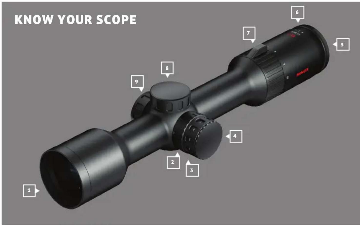
1 | Objective
2 | Parallax compensation
3 | Illumination adjustment
4 | Battery compartment
5 | Ocular
6 | Diopter adjustment
7 | Variable power ring
8 | Elevation adjustment
9 | Windage adjustment
SCOPE OF DELIVERY
■ MINOX riflescope
■ Objective and eyepiece cover
■ Allen key for reticle adjustment
■ Cleaning cloth
■ Type battery CR 2032 (inserted into device)
■ Instructions
MOUNTING
We strongly recommend having your scope mounted by a qualified gunsmith or professional workshop to ensure that the gun and riflescope are properly aligned.
DIOPTER ADJUSTMENT
The purpose of the diopter adjustment is to adjust the scope to the user's eye and compensate for individual prescriptions. If corrective glasses are to be worn when shooting, the diopter should be adjusted while wearing the glasses.
Note: When making adjustments on the riflescope, please adhere to the safety rules when handling your weapon.
To adjust the focus, first turn the diopter ring to the highest magnification and turn slowly in the opposite direction until you have reached the sharpest possible image. For best results, look at a neutral colored object in the distance like a cloudy sky or tree line. When looking through the scope, the reticle must be in sharp focus without having to make any further adjustments. Even though the eye can compensate for a suboptimal focus for some time, this results in eye fatigue after prolonged use.
ADJUSTING THE MAGNIFICATION
Turn the variable power ring towards the front of the eyepiece to your desired magnification. Turning clockwise will decrease the power and counter-clockwise will increase the power.
PARALLAX COMPENSATION
Parallax is the visible movement of the reticle over the target image. This occurs when the observing eye moves vertically or horizontally behind the riflescope and the scope has not yet been adjusted parallax-free to the target distance. This movement is also called parallax error and is a displacement of the apparent position of an object viewed along two different lines of sight.
Parallax compensation (8, see page 32) brings the target image into the same focal plane as the reticle. The target image as seen by the shooter is brought into focus and hereby eliminates parallax errors. To determine if the riflescope is parallax-free at the desired distance, move your head up and down, and from side to side while looking at the target through the riflescope.
If the reticle appears to be moving while doing this (make sure that the weapon is absolutely still), the parallax adjustment has not been set at the desired distance and needs to be readjusted. If the image is still out of focus even though the parallax compensation has been properly set, check the diopter adjustment.
Due to thermal expansion of the riflescope and varying atmospheric conditions, the markings on the parallax compensation (8) cannot be accurate under all circumstances – they serve mostly as an indication of which direction it should be turned. If high precision is required, the parallax should always be adjusted under the current conditions using the procedure described above.
ZEROING PROCESS
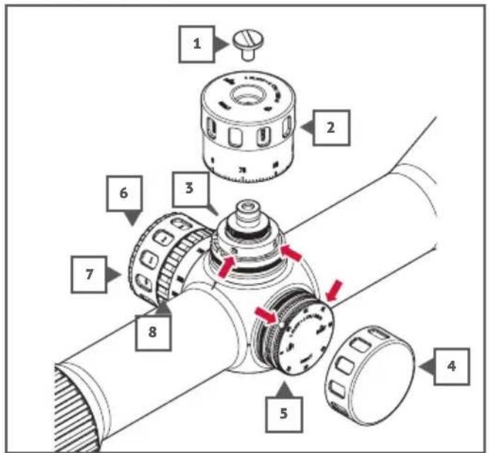
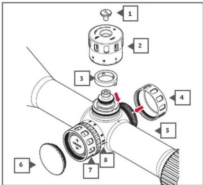
- Retaining screw
- Adjustment turret (elevation)
- Zero stop ring
- Protective caps
- Adjustment turret (lateral)
- Battery compartment
- Adjusting illuminated reticle
- Parallax compensation
Adjustment turrets with screw-on caps
The RS-4 scopes feature flat adjustment turrets with screw caps (with the exception of the elevation adjustment turret of the 3-12x56 BDC).
To zero in, first unscrew the elevation and lateral adjustment caps (4). Below this there are rotatable adjustment turrets (5) with a scale and a reference point for the zero setting. Each click and scale graduation of the adjustment turret means a change in the point of impact of 1 cm at 100 m. A clockwise turn shifts the target downwards or to the left. A counterclockwise turn shifts the target upwards or to the right.
Once the desired zero position is set, release the screws (arrows) on the side of the adjustment turret a quarter turn using the hexagon socket key. Now turn the adjustment turret so that the zero marking is aligned with the reference mark on the base of the turret. Then carefully retighten both socket head screws.
BDC adjustment turret (MODEL 3-12X56 BDC)
The BDC adjustment turret can be locked. To unlock the BDC turret, turn it upwards. In the upper setting, the reticle can be adjusted by turning the turret. To lock, push the turret back down to the desired position.
The BDC turret also features a zero stop that can be adjusted so that the adjustment turret can be turned exactly as far as the set target shot and then stops. In practice, this helps find the zero setting again by simply turning the adjustment turret clockwise as far as it will go.
To zero in the BDC adjustment turret and adjust the zero stop, proceed as follows:
- Remove the retaining screw (1) with a coin, for example.
- Remove the adjustment turret.
- Loosen the two socket head screws of the zero stop ring (3) by a quarter turn and remove the zero stop ring.
- Replace the adjustment turret and screw in place with the retaining screw.
The scope turret can now be turned freely in both directions in the unlocked position to zero it in.
- Retaining screw
- Adjustment turret (elevation)
- Zero stop ring
- Protective caps
- Adjustment turret (lateral)
- Battery compartment
- Adjusting illuminated reticle
- Parallax compensation
Once you have zeroed in the weapon, proceed as follows to adjust the zero stop and to zero the adjustment cap.
- Remove the retaining screw (1) and the adjustment turret (2).
- Fit the zero stop ring as shown and turn it clockwise as faras it will go.
- Carefully tighten the socket head screws of the zero stop ring.
- Position the adjustment turret so that the zero mark on the adjustment turret is aligned with the index mark on the telescope body.
- Screw the adjustment turret (2) tight with the retaining screw (1).
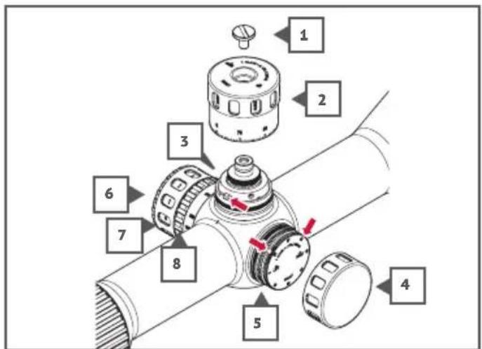
- Retaining screw
- Adjustment turret (elevation)
- Zero stop ring
- Protective caps
- Adjustment turret (lateral)
- Battery compartment
- Adjusting illuminated reticle
- Parallax compensation
ILLUMINATED RETICLE AND BATTERY CHANGE
Your MINOX riflescope is equipped with an illuminated reticle and is powered by a CR 2032 battery. The device is supplied with the batteries installed. Looking towards the front of the riflescope, the illumination unit can be found on the left of the main tube.
Proceed as follows to change the battery:
- Turn the battery cover (6) counterclockwise until it is released.
- Remove the old battery. Now insert the new battery, so that the minus pole is pointing towards the receiver.
- Screw the battery cover (6) clockwise to close again.
The adjustment wheel (7) is used to switch the illuminated reticle on and off. The illuminated reticle is switched off at level 0, in relation to the reference mark on the telescope body. Turn the adjustment wheel to level 1 to switch on the illuminated reticle of your scope. The brightness of the illuminated reticle can be adjusted in 10 click levels using the adjustment wheel. There is an "Off" setting with click levels between the brightness levels. Once you have selected the suitable brightness setting, you can switch the illuminated reticle off and back on again with only one click without having to search for the suitable brightness again.
To increase battery life, the illuminated reticle automatically switches off if the brightness setting is not operated for 3 hours. If the brightness setting is changed, the reticle lighting switches back on again.
RETICLE
In the RS-4 scopes, the reticle is in the second focus plane. The reticle is not magnified when changing magnification, but always remains the same, so the reticle subtension of these riflescopes depends on the magnification.
RETICLE COVER DIMENSIONS
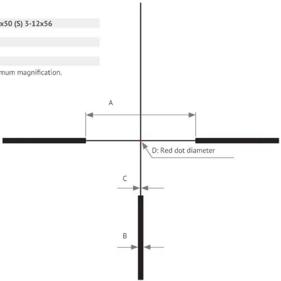
Reticle #4 1-4x24 2.5-10x42 2.5-10x50 (S) 3-12x56
A 250 100 100 83.3
B 12.5 5 5 4.2
C 2.5 1 1 0.8
D 2.5 1 1 0.8
All dimensions in cm at 100 m at maximum magnification.
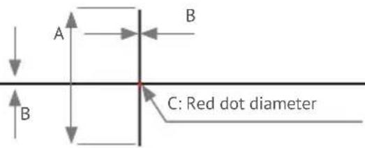
Reticle #54 1-4x24
A 55
B 3.6
C 2.5
All dimensions in cm at 100 m at maximum magnification.
CARE AND MAINTENANCE
The required maintenance of the tube and controls is limited to the removal of dust and dirt that can affect the operational elements of the riflescope. Dust, sand and dirt should be rinsed off under running water and the scope carefully patted dry with a clean cloth afterwards.
Note: Do not make any changes to the riflescope other than those described in these instructions.
Refrain especially from unscrewing or removing elements as the seals can be damaged or mechanical functions of the riflescope adversely affected, thus voiding the warranty.
The lenses should be protected by caps or similar to avoid damage and soiling when the riflescope is not in use.
The lenses and seals must not come into contact with oil or solvents. When cleaning your weapon, make sure that the rifle-scope is protected from contact with cleaning agents.
When cleaning the lenses with commercial lens cleaning products, the manufacturer's instructions must be observed. Cleaning cloths and pens must be clean and free of particles as these may cause damage when rubbed onto the lens surfaces. Coarse dirt can be rinsed off under running water and the lenses gently patted dry with a soft cloth. The lenses should only be cleaned when absolutely necessary.
Note: When rinsing the riflescope under running water, avoid strong jets of water as this may damage the seals.
TROUBLESHOOTING
Accuracy problems
One of the most common causes for inaccuracy (excessively large groups, double groups, stringing or flyers) is caused by improper mounting of the riflescope. Check all mounting components for tightness. Furthermore, make sure that the barrel is free of oil, cleaning agents and excessive fouling by powder residue and projectile debris. Use ammunition from the same manufacturer and lot number, and place the weapon on a solid surface such as a sandbag.
If accuracy problems should persist, please contact a qualified gunsmith to have your weapon examined.
Fogging
Internal lens surface fogging is the result of broken seals, allowing moisture to enter the scope. If the seal has failed under normal use, MINOX will repair or replace the scope in accordance with the MINOX warranty terms. However, fogging is most commonly the result of scope disassembly, which is not covered by the MINOX warranty.
With any internal fogging, return the scope to your authorized MINOX dealer or the MINOX service center for repair.
External lens surface fogging
External lens surface fogging is a common problem under the right temperature and humidity conditions. It cannot be avoided. Anti-fogging solutions may offer some relief, but simply wiping with a clean cloth is the most effective treatment. Avoid breathing on the eyepiece lens in cold weather.
SERIAL NUMBER
The individual serial number of the MINOX scope can be found on the underside of the eyepiece head.
SERVICING
Avoid unnecessary expense and delays by first checking all the user information and troubleshooting suggestions before returning your scope for service. If service is required, follow these instructions to send your MINOX scope directly to the service center:
- Pack the scope with adequate packing materials to prevent damage.
- Ship your scope prepaid and insured to your authorized MINOX dealer or local MINOX distributor:
Germany
Please send your MINOX riflescope to authorized dealers in all other countries.
You can find these addresses under: www.minox.com/service.
- Include a detailed description of the problem along with a copy of the original sales receipt.
CONDITIONS OF WARRANTY
With the purchase of this MINOX riflescope you have acquired a product that has been manufactured and inspected in accordance with especially high quality standards. For this product, we provide a legal warranty of 2 years in accordance with the following regulations from the day of purchase at an authorized dealer:
- During the warranty period we shall compensate complaints based on faulty manufacture with repair, replacement of defective parts or by replacement with an identical flawless product at our own discretion. Consequential claims, regardless of manner or legal argument in connection with this warranty, will not be accepted.
-
Claims under warranty are null and void if the defect has been caused by improper handling – which also can include the combined use of non MINOX accessories – if the MINOX product is serviced by unauthorized persons or workshops, or if the serial number has been made unreadable.
-
Warranty claims can only be made by submission of the printed receipt as proof of purchase from an authorized dealer.
-
When submitting claims under warranty, please return the MINOX riflescope together with the proof of purchase and a description of the complaint to MINOX GmbH in Germany, or the nearest MINOX dealer.
Extended MINOX Warranty Service
This MINOX product is covered by an extended warranty service of 10 years from the date of purchase for mechanical and optical aspects (excluding electrical aspects and add-on parts). The following regulations are applicable to the extended warranty service:
- In the event of faults due to defective materials or processing, during the warranty period MINOX will accept liability for the materials costs, it being understood that at its sole discretion the product or the defective component may be refurbished, repaired or replaced.
-
The warranty service does not affect your statutory rights. If a warranty claim is made after the end of the production cycle, MINOX reserves the right to repair the defective product or to replace it with an equivalent product.
-
MINOX will not accept liability for repairs not performed by MINOX, nor for damage arising from improper use, negligence, accidents or other intervention in the product by persons not authorised to do so. The warranty lapses if the damage arises from the use of add-on parts or accessories not approved by MINOX. The warranty lapses if the damage occurs due to the elements such as natural catastrophes, flood, storm, hail or fire. The warranty also lapses if the damage occurs during wartime or during a conflict situation.
- Wearing parts such as eyecups, carrying straps, rubber parts, protective caps, batteries and the like are not covered by the MINOX extended warranty service.
- The MINOX extended warranty service is valid only if when a claim is made under warranty the invoice carrying the date of purchase and showing the serial number can be submitted. Products for which no such proof of purchase can be submitted are excluded from the warranty service, unless the equipment can be identified by its serial number. In that case, please contact MINOX Customer Service before returning the equipment.
- The general conditions of business (gcb) of the Blaser Group GmbH can be viewed at:
https://www.minox.com/de/Informationen/AGB/
CE MARKING
Tests to obtain the CE marking

CE marking / The devices are compliant with the EU directives:
EMV-Directive 2014/30/EU
RoHS-Directive 2011/65/EU
Low Voltage Directive 2014/35/EU
The full text for the EU conformity declaration is available on the following website:
Low voltage SI 2016 No. 1101

Blaser Group GmbH
Ziegelstadel 1
88316 Isny
Phone: +49 7562 702-0
Fax: +49 7562 702-343
D 54.5 62.0 62.0 62.0
E 96.8 97.0 97.0 97.0
F 30.0 48.0 56.0 62.0
G 45.4 45.4 45.4 45.4
H 46.8 46.8 46.8 46.8 / 60.2 (BDC)
I 14.8 14.8 14.8 14.8 / 28.2 (BDC)
J 61.8 73.1 73.1 73.1
K 14.8 14.8 14.8 14.8
L 17.0 28.3 28.3 28.3
M 30.0 30.0 30.0 30.0
N 46.0 46.0 46.0 46.0
TECHNICAL DATA
| Model | 1-4x24 | 2.5-10x42 |
| Magnification | 1 - 4 x | 2.5 - 10 x |
| Lens diameter (mm) 24 42 | ||
| Diameter of exit pupil (mm) | 10.0 - 6.0 | 10.0 - 4.2 |
| Visual field in m at 100 m | 40.0 - 10.0 | 16.0 - 4.0 |
| Distance to exit pupil (mm) | 90 | 90 |
| Dioptre adjustment | -3 / +2 | -3 / +2 |
| Elevation and lateral adjustment (per click) | 1 cm / 100 m | 1 cm / 100 m |
| Reticle adjustment range (elevation / lateral) | ±200 cm / 100 m | ±200 cm / 100 m |
| Parallax adjustment | 100 m fix | 10 m to ∞ |
| Illuminated reticle | Yes, fibre optics | Yes, fibre optics |
| Focus plane | 2 | 2 |
| Power supply for the illuminated reticle | CR 2032 | CR 2032 |
| Nitrogen filling | Yes | Yes |
| Anti-fog and watertight | Yes, 4 m for 30 min | Yes, 4 m for 30 min |
| Central tube diameter (mm) | 30 | 30 |
| Length (mm) | 274 | 295 |
| Weight (g) | 470 | 635 |
| Order no. | 80413876 (#4) | 80414732 (#54) | 80413879 |
| 10.0 - 5.0 | 10.0 - 4.6 |
| 16.0 - 4.0 | 13.3 - 3.3 |
| Yes, fibre optics | Yes, fibre optics |
| 2 | 2 |
| CR 2032 | CR 2032 |
| Yes | Yes |
| Yes, 4 m for 30 min | Yes, 4 m for 30 min |
| 344 | 365 |
| 660 / 690 (S) | 745/755 (BDC) |
| 80413878 I 80415820 (S) | 80413880 I 80414287 (BDC) |
BIENVENUE CHEZ MINOX!
CONDITIONS DE LA GARANTIE
Directive RoHS 2011/65/UE
DIMENSIONES EN MM
1-4x24 2.5-10x42 2.5-10x50 (S) 3-12x56 (BDC)
A 274 295 344 365
D 54,5 62,0 62,0 62,0
E 96,8 97,0 97,0 97,0
F 30,0 48,0 56,0 62,0
G 45,4 45,4 45,4 45,4
N 46,0 46,0 46,0 46,0
DATOS TÉCNICOS
Dimensioni in mm....113
Dati Tecnici 114
D 54,5 62,0 62,0 62,0
E 96,8 97,0 97,0 97,0
F 30,0 48,0 56,0 62,0
G 45,4 45,4 45,4 45,4
N 46,0 46,0 46,0 46,0
DATI TECNICI
MÉRETEK MM-BEN
1-4x24 2.5-10x42 2.5-10x50 (S) 3-12x56 (BDC)
A 274 295 344 365
D 54,5 62,0 62,0 62,0
E 96,8 97,0 97,0 97,0
F 30,0 48,0 56,0 62,0
G 45,4 45,4 45,4 45,4
N 46,0 46,0 46,0 46,0
MÜSZAKI ADATOK
KOMPENSACJA PARALAKSY
WYMIARY W MM
1-4x24 2.5-10x42 2.5-10x50 (S) 3-12x56 (BDC)
A 274 295 344 365
D 54,5 62,0 62,0 62,0
E 96,8 97,0 97,0 97,0
F 30,0 48,0 56,0 62,0
G 45,4 45,4 45,4 45,4
N 46,0 46,0 46,0 46,0
DANE TECHNICZNE
D 54,5 62,0 62,0 62,0
E 96,8 97,0 97,0 97,0
F 30,0 48,0 56,0 62,0
G 45,4 45,4 45,4 45,4
N 46,0 46,0 46,0 46,0

- WILLKOMMEN BEI MINOX
- ABMESSUNGEN IN MM
- CONTENTS
- SAFETY RULES AND INSTRUCTIONS FOR USE
- DISPOSAL
- Disposal of waste electrical equipment and batteries
- GENERAL INSTRUCTIONS FOR USE
- INTENDED USE
- SCOPE OF DELIVERY
- MOUNTING
- DIOPTER ADJUSTMENT
- ADJUSTING THE MAGNIFICATION
- PARALLAX COMPENSATION
- Adjustment turrets with screw-on caps
- BDC adjustment turret (MODEL 3-12X56 BDC)
- ILLUMINATED RETICLE AND BATTERY CHANGE
- RETICLE
- RETICLE COVER DIMENSIONS
- Reticle #54 1-4x24
- CARE AND MAINTENANCE
- TROUBLESHOOTING
- Accuracy problems
- Fogging
- External lens surface fogging
- SERIAL NUMBER
- SERVICING
- Germany
- CONDITIONS OF WARRANTY
- Extended MINOX Warranty Service
- CE MARKING
- Tests to obtain the CE marking
- BIENVENUE CHEZ MINOX!
- CONDITIONS DE LA GARANTIE
- DIMENSIONES EN MM
- MÉRETEK MM-BEN
- KOMPENSACJA PARALAKSY
- WYMIARY W MM
Brand : MINOX
Model : RS-4
Category : Riflescope