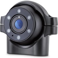
PerfectView CAM 301X - Rear Camera DOMETIC - Free user manual and instructions
Find the device manual for free PerfectView CAM 301X DOMETIC in PDF.


User questions about PerfectView CAM 301X DOMETIC
0 question about this device. Answer the ones you know or ask your own.
Ask a new question about this device
Download the instructions for your Rear Camera in PDF format for free! Find your manual PerfectView CAM 301X - DOMETIC and take your electronic device back in hand. On this page are published all the documents necessary for the use of your device. PerfectView CAM 301X by DOMETIC.
USER MANUAL PerfectView CAM 301X DOMETIC
natural_image
Line drawing of a mechanical component with a coiled spring and bulb (no text or symbols)CAM301
EN
Additional camera
Installation and Operating Manual ..... 6
TAR
Kugelkamera
natural_image
Technical diagram showing a mechanical assembly with intersecting lines and arrows indicating motion (no text or symbols)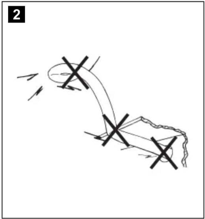
natural_image
Simple line drawing of a mechanical or electrical component with no text, numbers, or symbols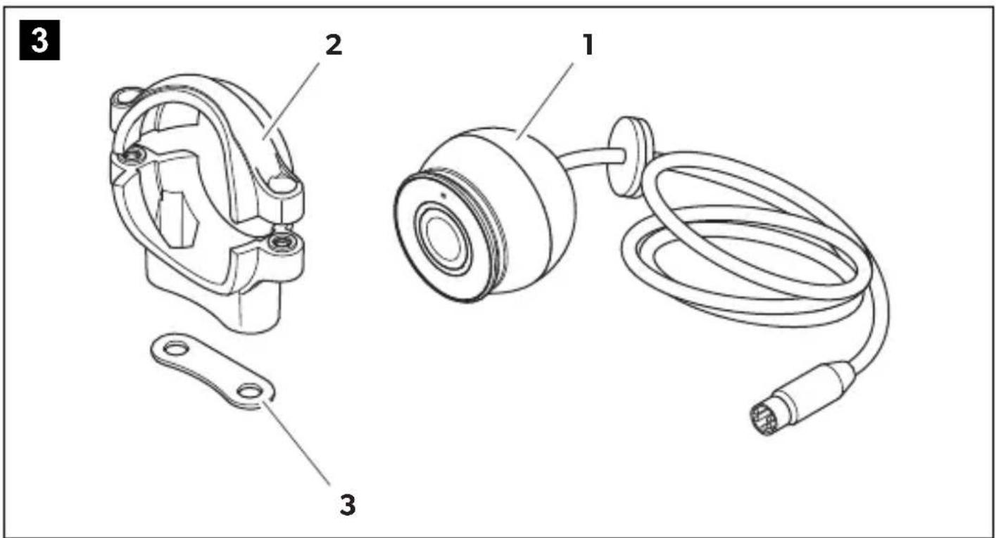
text_image
Technical diagram showing three labeled components of a mechanical assembly: a housing, a motor, and a cable with connectors.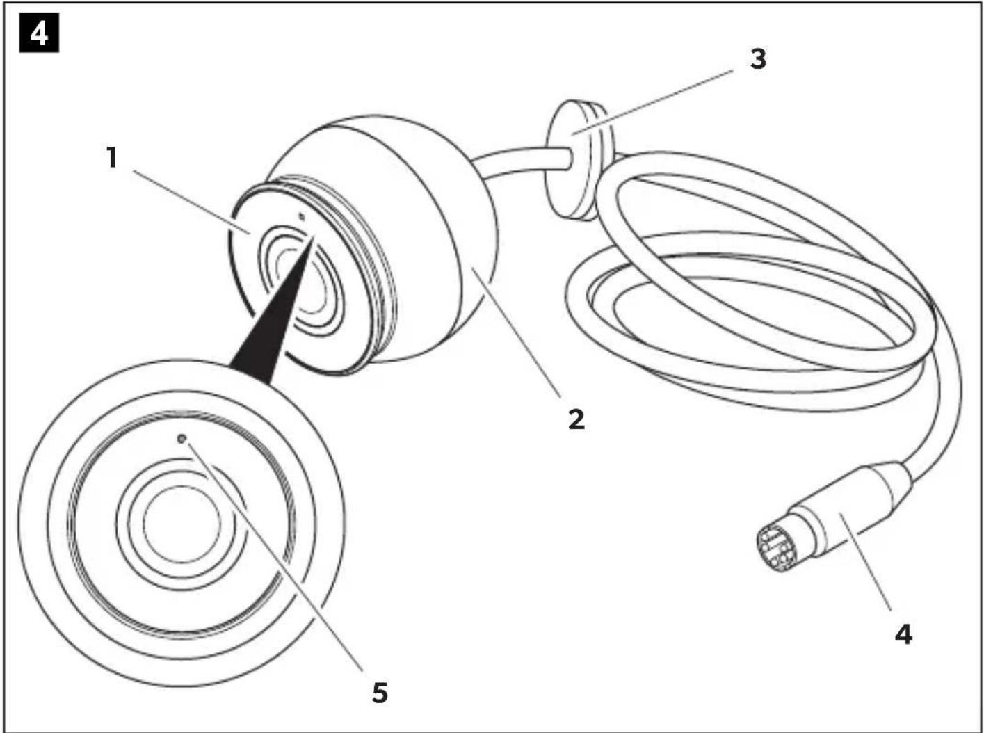
text_image
Technical diagram of a mechanical device with labeled parts including a coiled cable, shaft, and housing.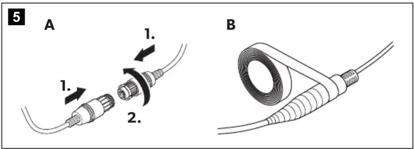
text_image
5 A 1. 1. 2. B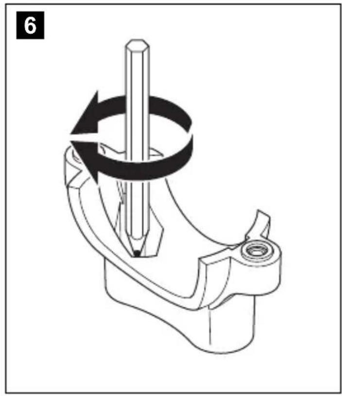
natural_image
Mechanical component diagram showing a rotating shaft and base with a circular arrow indicating rotation (no text or symbols)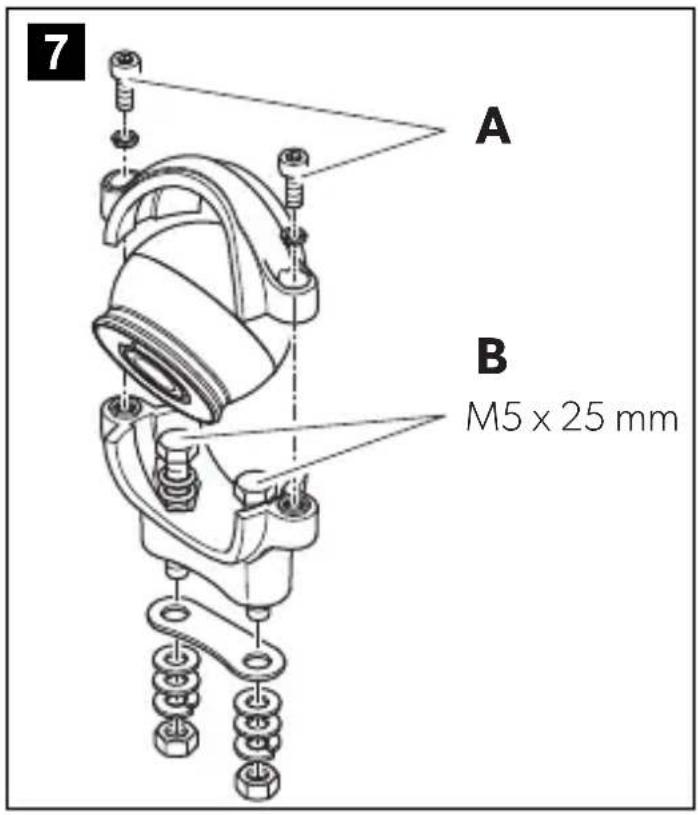
text_image
7 A B M5 x 25 mm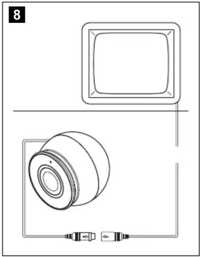
natural_image
Technical line drawing of a mechanical component with a circular base and connected tubing (no text or symbols)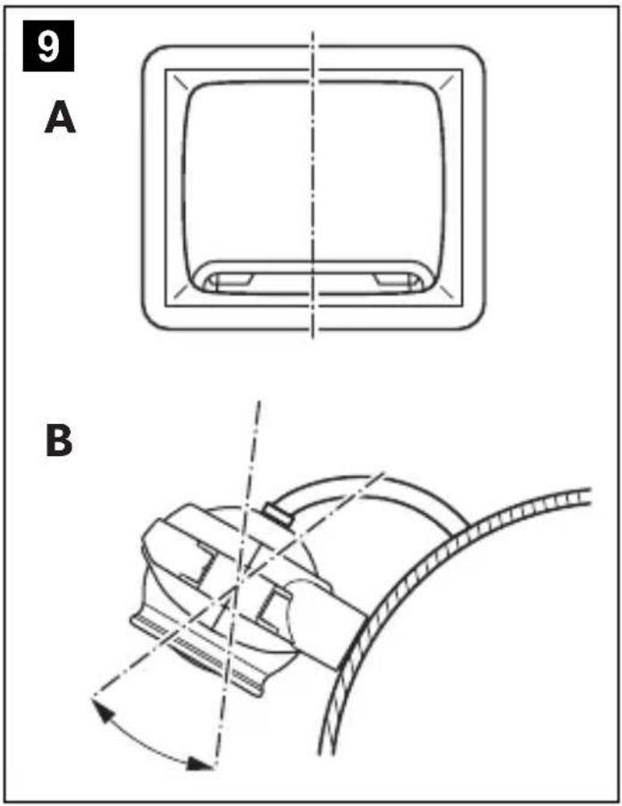
text_image
9 A B10
B
natural_image
Diagram of a computer mouse with a cable and labeled component 'gn' (no text or symbols beyond label)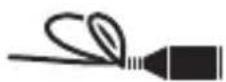
natural_image
Simple line drawing of a trapezoidal object inside a rectangular frame, with control buttons at the bottom (no text or symbols)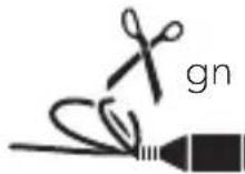
natural_image
Front view of a rectangular monitor with control buttons at the bottom (no text or symbols on the screen)| DE | EN | FR | ES | IT | NL | DA | SV | |
| ge | Gelb | Yellow | Jaune | Amarillo | Giallo | Geel | Gul | Gul |
| gn | Grün | Green | Vert | Verde | Verde | Groen | Grøn | Grön |
| NO | FI | PT | RU | PL | CS | SK | HU | |
| ge | Gul | Keltainen | Amarelo | Желтый | Żółty | Żlutá | Żltá | Sárga |
| gn | Grønn | Vihreä | Verde | Зеленый | Zielony | Zelená | Zelená | Zöld |
Please read this instruction manual carefully before installation and first use, and store it in a safe place. If you pass on the product to another person, hand over this instruction manual along with it.
Table of contents
1 Description of symbols....6
2 Safety and installation instructions....7
3 Scope of delivery 9
4 Accessories....9
5 Intended use....9
6 Technical description....10
7 General instructions for electrical connection....10
8 Fitting the camera 11
9 Connecting the camera 14
10 Checking the function and setting the camera ..... 14
11 Cleaning and caring for the camera....15
12 Warranty 15
13 Disposal....15
14 Technical data....16
1 Description of symbols

WARNING!
Safety instruction: Failure to observe this instruction can cause fatal or serious injury.

CAUTION!
Safety instruction: Failure to observe this instruction can lead to injury.

NOTICE!
Failure to observe this instruction can cause material damage and impair the function of the product.

NOTE
Supplementary information for operating the product.
2 Safety and installation instructions
The manufacturer accepts no liability for damage in the following cases:
• Damage to the product resulting from mechanical influences and incorrect connection voltage
• Alterations to the product without express permission from the manufacturer
- Use for purposes other than those described in the operating manual
Please observe the prescribed safety instructions and stipulations from the vehicle manufacturer and service workshops.

WARNING!
Inadequate supply cable connections could result in short circuits, causing:
- Cable fires
• The airbag being triggered
• Damage to electronic control equipment
• Electrical malfunctions (indicators, brake light, horn, ignition, lights)

NOTICE!
To prevent the risk of short circuits, always disconnect the negative terminal of the vehicle's electrical system before working on it.
If the vehicle has an additional battery, its negative terminal should also be disconnected.
Therefore, please observe the following instructions:
- When working on the following cables, use only insulated cable lugs, plugs and tab sleeves.
- 30 (direct supply from positive battery terminal)
- 1 5 ( connected positive terminal, behind the battery)
- 31 (return cable from the battery, earth)
-58 (reversing light)
Do not use porcelain wire connectors.
- Use a crimping tool to connect the cables. For permanent connections, you can solder the cable ends together and then insulate them.
- Screw the cable when connecting cable 31 (earth)
- Screw on the cable using a cable terminal and serrated washer to one of the vehicle's earth bolts or
- screw the cable to the bodywork using a cable terminal and a self-tapping screw.
Make sure there is a good earth connection.
If you disconnect the negative terminal of the battery, all data stored in the volatile memories will be lost.
- The following data must be reset, depending on the vehicle equipment options:
- Radio code
- Vehicle clock
- Timer
- On-board computer
- Seat position
You can find instructions for making these settings in the operating manual.
Note the following instructions during installation:
- Secure the parts of the camera installed in the vehicle in such a way that they cannot become loose under any circumstances (sudden braking, accidents) or cause injuries to the occupants of the vehicle.
- Secure any parts of the system concealed by the bodywork in such a manner that they cannot be come loose or damage other parts or cables, or impair vehicle functions (steering, pedals, etc.).
- To prevent damage when drilling, make sure there is sufficient space on the other side for the drill head to come out (fig. 1, page 2).
- Deburr all drill holes and treat them with a rust-protection agent.
• Always follow the safety instructions of the vehicle manufacturer.
Some work (e.g. on retention systems such as the AIRBAG etc.) may only be performed by qualified specialists.
Observe the following instructions when working with electrical parts:
- When testing the voltage in electrical cables, only use a diode test lamp or a voltmeter. Test lamps with a bulb consume too much voltage, which can damage the vehicle's electronic system.
- When making electrical connections, ensure that:
– they are not kinked or twisted
– they do not rub on edges
– they are not laid in sharp-edged ducts without protection (fig. 2, page 2).
• Insulate all connections.
- Secure the cables against mechanical stress with cable binders or insulating tape, for example, to existing lines.
The camera is watertight. However, the seals on the camera cannot withstand a high-pressure cleaner. Therefore, you should observe the following instructions when handling the camera:
- Do not open the camera, as this impairs the tightness and the function of the camera.
- Do not pull at the cables, as this impairs the leak-tightness and the function of the camera.
- The camera is not suitable for submerged operation.
| 3 | S | c | o | p | e | o | f | d | e | l |
Quantity Description Ref. no.
| 1 | 1 | Camera |
| CAM301 color camera 9600005898 |
21 Top and bottom camera holder
| 3 | 1 | 1 | n | s | u | 1 |
| - | 1 | F | a | s | t | e |
4 Accessories
Description Ref. no.
| Extension cable, 5 m | 9600000206 |
| Extension cable, 10 m | 9600000207 |
| Extension cable, 20 m | 9600000208 |
| Spiral cable for trailer operation | 9600000235 |
5 l n t e n d e d u s
The CAM 301 color camera is primarily intended for use in vehicles. It can be used in reversing video systems that serve to monitor the area directly next to or behind the vehicle from the driver's seat, for example, during maneuvering or parking.
Reversing video systems are designed merely as an additional aid for reversing, however this does not relieve you of the duty to take proper care when reversing.
6 Technical description
6.1 Function description
The camera is located in an aluminium case and transfers the image via a cable to a monitor. The built-in infrared LEDs improve night vision.
The camera consists of the following elements:
| No. in fig. 4, page 3 | Description | |||||
| 1 Infrared LEDs | ||||||
| 2 | S | I | e | e | v | e |
| 3 | 6 | - | p | i | n | c |
| 4 | P | I | u | g | ||
| 5 | L | D | R | s | e | n |
7 General instructions for electrical connection
7.1 Laying cables

NOTICE!
The cables may not be exposed for long periods to solvents such as benzene, since they can damage the cable.

NOTE
- As far as possible, use original ducts for laying the cables, or other suitable options such as paneling edges, ventilation grills or dummy plugs. If no openings are available, you must drill holes for the cables. Check beforehand that there is sufficient space on the other side for the drill head to emerge.
- Cables and connections that are not properly installed will cause malfunctions or damage to components. Correct installation of cables and connections ensures lasting and trouble-free operation of the retrofitted components.
Therefore, please observe the following instructions:
- Wherever possible, lay cables inside the vehicle, as they are better protected there than outside.
If you do need to lay a cable outside the vehicle, ensure that it is well fastened (use additional cable ties, insulating tape etc.). - To prevent damage to the cables when laying them, ensure that they are far enough away from hot or moving vehicle components (exhaust pipes, drive shafts, light systems, fans, heaters, etc.). Use corrugated piping or other protective materials to protect against mechanical wear.
- When laying the cables, make sure:
– they are not kinked or twisted
– they do not rub on edges
- they are not laid in sharp-edged ducts without protection (fig. 2, page 2).
- Attach the cables securely in the vehicles to prevent tripping hazards. This can be performed by using cable binders, insulating tape or gluing in place with adhesives.
- Protect every through-hole made in the bodywork against water penetration, e.g. by using a cable with a sealant and by spraying the cable and the cable sleeve with sealant.

NOTE
Only start sealing through-holes when you have completed all installation work on the camera and have laid the required cable lengths.
8 Fitting the camera

NOTICE!
Select a location for the camera and attach it firmly enough so that it cannot under any circumstances fall off and injure bystanders (e.g. by being knocked off by branches brushing over the roof of the vehicle).

NOTE
If installing the camera alters the vehicle height or the length specified in the vehicle documents, your vehicle must be inspected by the appropriate authorities. This authority must note any such changes your vehicle documents.
Note the following instructions during installation:
- To provide a suitable viewing angle, the camera must be attached at a height of at least 2 m. Ensure that you have a firm place from which to work when mounting the camera.
- Make sure that the installation location of the camera is sufficiently firm (e.g. to prevent the camera from being knocked down by branches that may brush the roof of the vehicle).
- Always use the supplied insulation pad (fig. 3 3, page 2). This prevents residual currents due to bad ground connections in the vehicle. Residual current can cause lines of interference in the picture or buzzing in the loudspeakers or even damage components.
- Observe the fastening instructions:
- There must be sufficient space behind the chosen installation location to be able to carry out the mounting procedure.
- Suitable measures must be taken to prevent water penetrating through any holes made (e.g. by using screws and sealant and/or spraying the outer attachment parts with sealant).
-
The location on the body where you wish to attach the camera must be rigid enough to allow the camera to be tightly fastened.
-
Check beforehand that there is sufficient space on the other side for the drill head to come out (fig. 1, page 2).
• If you are not sure about the location you have chosen, ask your vehicle manufacturer or dealer.

NOTE
We recommend greasing the threads of the bolts to prevent corrosion.
To perform the installation, proceed as follows:
▶ Hold the lower camera holder on the selected installation location and mark two drilling points (fig. 6, page 4).
Using a hammer and center punch, gently pre-punch the previously marked points to prevent the drill head from slipping off.
If you want to screw on the bottom camera holder with self-tapping screws

NOTICE!
Self-tapping screws may only be fastened to steel metal with a minimum thickness of 1.5 mm.
▶ Drill the holes, with a ∅ of 2 mm, at each of the markings.
▶Deburr all drill holes and apply rust-protection.
Place the insulating plate (fig. 3 3, page 2) on the installation location of the lower camera holder.
The insulating plate also serves as a seal and paint protection.
▶ Screw on the camera holder using the self-tapping screws.
If you want to attach the lower camera holder with screws when installing

NOTICE!
Ensure that nuts cannot be pulled through the body shell when they are tightened. Use larger washers or metal plates if necessary.
▶ Drill the holes, with a ∅ of 5.5 mm, at each of the markings.
▶Deburr all drill holes and apply rust-protection.
Place the insulating plate (fig. 3 3, page 2) on the installation location of the lower camera holder.
The insulating plate also serves as a seal and paint protection.
▶ Screw on the lower camera bracket with the M5 x 25 mm threaded screws (fig. 7 A, page 4). Depending on the thickness of the construction, you may require longer threaded screws.
Fastening the camera
▶Push the camera into the bottom camera holder.

NOTE
Keep in mind that the LDR sensor (fig. 4 4, page 3) should be faced downwards so that the image is displayed correctly on the monitor.
▶ Fasten the camera loosely with the upper camera holder and the two screws (fig. 7 B, page 4).

NOTE
Do not tighten the two screws until you have aligned the camera (see chapter "Checking the function and setting the camera" on page 14).
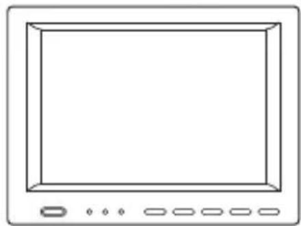
If necessary, you may have to first install and electrically connect a monitor (see principle circuit diagram fig. 8, page 4).
Creating a through-hole for the camera connection cable

NOTE
If possible, use available openings, such as ventilation grilles, to feed the connection cables through. If there are no existing ducts, you must drill a hole of ∅ 16 mm. Check beforehand that there is sufficient space on the other side for the drill head to come out.
▶Drill a hole of ∅ 16 mm near the camera.
▶ Deburr all drill holes that have been made in the sheet metal and apply rust-protection.
▶ Seal the feed through with the cable sleeve (fig. 4 3, page 3).
9 Connecting the camera

NOTE
Lay the camera cable so that, should you need to remove the camera, you can access the plug connection between the camera and the extension cable easily. This simplifies dismantling considerably.
▶Guide the camera cable into the vehicle interior.
▶ Insert the camera cable plug into the socket of the monitor cable (fig. 8, page 4).

NOTE
- To minimize corrosion in the plug, apply a small amount of grease, such as pin grease, in one of the plugs.
- Extension cables are available if needed (see chapter "Accessories" on page 9).
- The cable plug connections are waterproof (IP67). As an option you can add a sealing tape to the connections (fig. 5 B, page 3).
10 Checking the function and setting the camera
▶Check the function of the camera after you have connected it to a monitor.
▶If necessary adjust the camera using the monitor image:
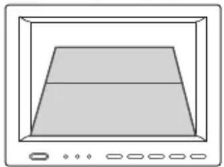
The monitor image should show the rear or the bumper of the vehicle at the bottom edge of the screen. The middle of the bumper should be in the middle of the screen (fig. 9, page 4).
▶Tighten the two fastening screws of the top camera holder.
Settings for contrast and brightness can be made on the monitor.
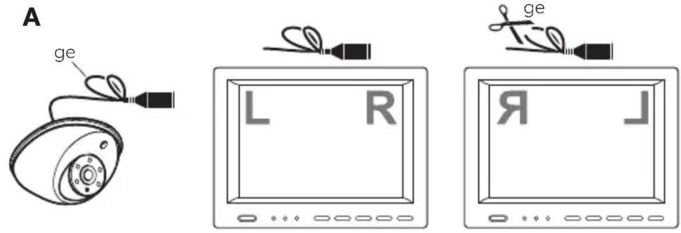
Activating mirror function
See fig. 10 A, page 5.
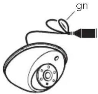
Deactivating distance markers
See fig. 10 B, page 5.
11 Cleaning and caring for the camera

NOTICE!
Do not use any sharp or hard objects for cleaning since they may damage the device.
▶Occasionally clean the device with a soft, damp cloth.
12 Warranty
The statutory warranty period applies. If the product is defective, please contact the manufacturer's branch in your country (see the back of the instruction manual for the addresses) or your retailer.
For repair and warranty processing, please include the following documents when you send in the device:
• A copy of the receipt with purchasing date
• A reason for the claim or description of the fault
13 Disposal
Place the packaging material in the appropriate recycling waste bins wherever possible.
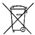
If you wish to finally dispose of the product, ask your local recycling centre or specialist dealer for details about how to do this in accordance with the applicable disposal regulations.
14 Technical data
| PerfectView CAM301 | |
| Ref. no.: 9600005898 | |
| Video system: PAL | |
| Image sensor: 1/3" color CMOS sensor | |
| Pixels: Approx. 320000 pixels | |
| Sensitivity without LED with LED: | 0.5 lux0 lux |
| Video output: 1 Vp-p 75 Ω | |
| Operating temperature: -20 °C to +70 °C | |
| Operating voltage: 10 V--- | to 16 V--- |
| Consumption: Max. 150 mA | |
| Dimensions W x H x D (with bracket): | 84 x 58 x 44 mm |
| Weight: approx. 80 g |
Certifications
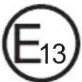
This device has E13 approval.
6 Description technique
dometic.com/sales-offices


